

Page 1
Operation / Installation Manual
Wireless Water
Water Heater
On/Off
Entry
Controllers
MC
Temp. Volume
Max Temp. Maintenance
Controller
No. 1 No. 2 No. 3
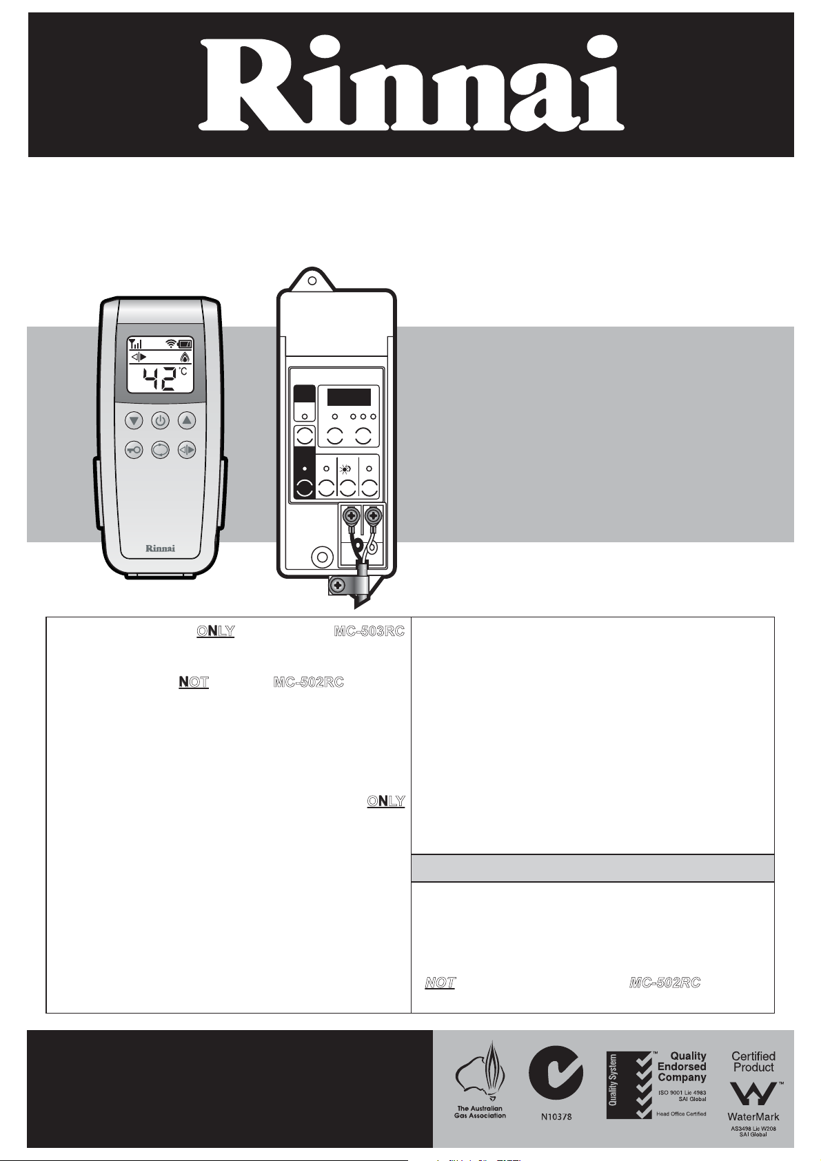
Model: MC-503RC
This manual applies ONLY to the Rinnai MC-503RC
wireless water controllers and transceivers.
This manual does NOT
water controllers and transceivers.
This manual must be used in conjunction with the
Rinnai Water Heater Operation / Installation Manual
supplied with Rinnai water heaters.
MC-503RC water controllers are compatible ONLY
with Rinnai water heater and remote controller
models shown.
Refer to the table on page 2 of this manual to
confirm the maximum number and combination of
controllers that can be fitted to your Rinnai water
heater model.
For information regarding compatibility with other
Rinnai water heater and water controller models
contact Rinnai.
apply to MC-502RC wireless
Compatible Rinnai water heater models:
INFINITY 32 REU-VR3237WG
INFINITY 26 REU-VR2626WG
INFINITY 26 Plus REU-VRM2630WD
INFINITY 26i REU-VR2632FFUG
INFINITY 20 REU-VR2024WG
INFINITY 16 REU-VR1620WG
ENVIROSMART REU-KR2430WG
V1500 REU-VR2426WB
V1200 REU-VR1620WB
HD250e REU-VRM3237WC
HD200e REU-VRM2632WC
HD200i REU-VRM2632FFUC
Refer to the inside front cover for additional Rinnai continuous flow
Compatible Rinnai wired remote controller
Universal MC-91Q
Deluxe Kitchen MC-100V
Deluxe Bathroom BC-100V
NOT
remote controller and tranceivers.
water heater models covered by this manual.
compatible with Rinnai MC-502RC wireless
This wireless water controller and transceiver
must be installed in accordance with the
manufacturer’s Installation Instructions.
All Rinnai gas products
are A.G.A. certified.
Distributed and serviced in Australia under a Quality
System certified as complying with ISO 9001 by
SAI Global
SAI Global
Page 2
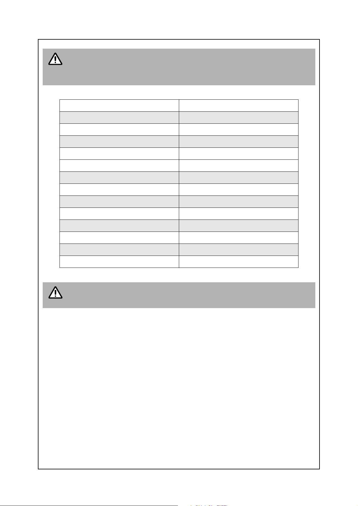
NOTE
This manual applies to some additional Rinnai continuous flow water heater models
not listed on the front cover of this manual.
The following table lists these additional models and their equivalent in terms of
wireless controller operation.
Model not listed on the front cover Equivalent model listed on front cover
REU-V3237WG REU-VR3237WG
REU-V2626WG REU-VR2626WG
REU-VM2630WD REU-VRM2630WD
REU-V2632FFUG REU-VR2632FFUG
REU-V2024WG REU-VR2024WG
REU-V1620WG REU-VR1620WG
REU-K2430WG REU-KR2430WG
REU-V2426WB REU-VR2426WB
REU-V1620WB REU-VR1620WB
IMPORTANT
REU-V2024WE REU-VR2024WG
REU-VM3237WC REU-VRM3237WC
REU-VM2630WC REU-VR2626WG
REU-VM2632FFUC REU-VRM2632FFUC
Other Rinnai continuous flow water heater models that are not listed above are
therefore not covered by this manual.
Page 3

OPERATION MANUAL
IMPORTANT INFORMATION .....................................................................................1
INSTALLATION AND SERVICING...................................... ......................................................... 1
A WARNING ABOUT HOT WATER............................................................................................. 1
RADIO COMMUNICATIONS........................................................................................................1
GENERAL WATER CONTROLLER INFORMATION.................................................2
USING WIRELESS WATER CONTROLLERS............................................................3
ABOUT THE WIRELESS WATER CONTROLLER (MC-503RC).................................................3
TURNING ON THE WATER HEATER. ........................................................................................3
ADJUSTING TEMPERATURE .................. ............................................................. .... ... ... ............3
TRANSFERRING PRIORITY BETWEEN WATER CONTROLLERS...........................................4
USING CHILD LOCK FUNCTION ................................................................................................4
WIRELESS WATER CONTROLLERS BATTERIES .................................................................... 5
SMARTSTART® PRE-HEAT OPERATION................................................................6
ABOUT THE SMARTSTART® PRE-HEAT SYSTEM .................................................................. 6
TROUBLESHOOTING.................................................................................................7
ERROR CODES........................................................................................................................... 7
SERVICE...................................................................................................................................... 7
INSTALLATION MANUAL ..........................................................................................8
CONTACT INFORMATION .......................................................................................17
Rinnai Australia i Operation Manual
Page 4
IMPORTANT INFORMATION
INSTALLATION AND SERVICING
Rinnai Wireless Transceivers can be connected to the water heater models listed on the cover page
by the end user in accordance with these Instructions. A qualified tradesperson is not required.
Rinnai Wireless Transceivers are also compatible with some older water heater models not listed on
the cover page of these Instructions. In this case they must be installed and commissioned by a
suitably qualified trades person. Contact Rinnai for information regarding compatibility with older
water heaters.
Regardless of water controller or transceiver installation, all Rinnai water heaters must only be
installed by an Authorised person.
Water controllers, transceivers and water heaters do not contain user serviceable parts and must only
be serviced and repaired by an authorised person.
Keep this manual in a safe place for future reference.
All dimensions referred to in this manual are in millimetres, unless otherwise specified.
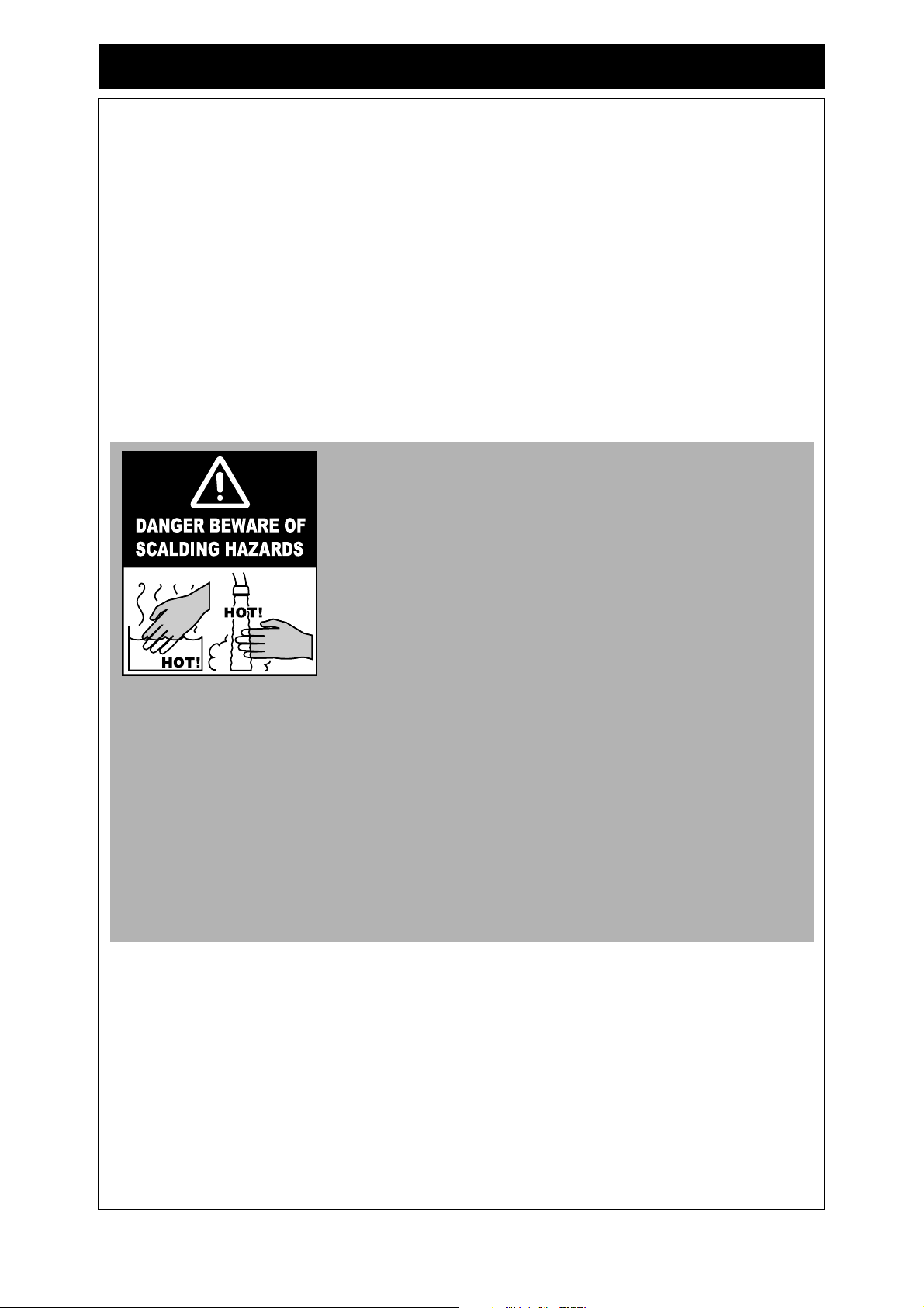
A WARNING ABOUT HOT WATER
Excessively hot water is dangerous, especially for young
children and the infirm. Rinnai water controllers allow you to
control the temperature of hot water to safe levels.
Water temperatures above 50°C can cause severe burns. Those
most at risk are children, disabled, elderly and the infirm.
ALWAYS......
Test the temperature of the water with your elbow before placing
your child in the bath, also carefully feel water bef ore bathing or
showering yourself.
Supervise children whenever they are in the bathroom.
Make sure that the hot water tap is turned off tightly.
CONSIDER.....
Installing child proof tap covers or child resistant taps (both
approaches will prevent a small hand being able to turn on the
tap).
Setting your appliance at a maximum temperature of 50°c
(contact Rinnai Australia).
NEVER….
Leave a toddler in the care of another child. they may not
understand the need to have the wat er t emp erature s et at a sa fe
level.
RADIO COMMUNICATIONS
Rinnai wireless water controllers are classified as short range radio communications devices and
referred to as Low Interference Potential Devices (LIPD’s) in AS/NZS 4268:2003*. As such, they
operate in the same radio frequency spectrum as many other devices classified as LIPD’s such as
garage door openers and keyless automobile entry systems. Although interference with other LIPD's
is unlikely, it is not guaranteed interference will not occur.
Rinnai wireless water controllers must not be used in the vicinity of other devices if radio interference
with such devices could result in a dangerous situation, unless it is verified that interference will not
occur. Possible examples are medical devices and fire alarms.
*AS/NZS 4268:2003 ‘Radio Equipment and systems – short range devices – Limits and methods of
measurement’.
Rinnai Australia 1 Operation Manual
Page 5
GENERAL WATER CONTROLLER INFORMATION
The MC-503RC Wireless water controller is a water resistant device, however
excessive exposure to water such as immersion may result in damage to the
NOTE
controller.
• DO NOT immerse the controller into water.
• AVOID direct exposure to water or steam as these conditions may cause a
malfunction.
• ALWAYS AVOID exposure to water when the battery compartment is open.
When cleaning your water controller use ONLY a damp cloth and a mild detergent.
Water controllers allow precise temperature control by the user. When used correctly, the hot water
unit will deliver the selected temperature, even when the water flow is varied, or more than one tap is
in use. Each remote controller ca n be individually programmed , however the water heat er can only
deliver one set temperature at any time. The available temperatures (°C) are as follows:
Master Controller (used in kitchen):
37, 38, 39, 40, 41, 42, 43, 44, 45, 46, 48, 50, 55°C* (60, 65°C HD models only)
Bathroom Controller (used in bathrooms, ensuites, toilets and laundry):
Hot Water Delivery: 37, 38, 39, 40, 41, 42, 43, 44, 45, 46, 48, 50°C
Whilst hot water outlets are open the set temperatu re may be lowered. However the set temperature
cannot then be raised above 43°C. In additio n transfer of 'priority' between controll ers is not possible.
These are safety features.
Suggested temperatures are:
Kitchen 50°C ~ 55°C*, Shower 37°C ~ 43°C
* Temperature may not be available on all installations. Rinnai water heaters can be programmed to deliver higher temperatures
via the kitchen controller. Contact Rinnai for more details.
These temperatures are suggestions only. You may find higher or lower temperatures more
comfortable. Maintaining lower temperatures helps sa ve ener gy. To o btain wa ter tem peratur es lowe r
than 37°C simply add cold water.
The temperature of outgoing hot water is constantly monitored by a built-in se nsor. If the temperature
of the outgoing hot water rises to more than 3°C above th e selected temperatur e shown on the d igital
monitor, the burner will automatically go out. The ‘In Use’ indicator will also go out. The burner will
ignite again once the outgoing hot water temperature falls to that shown on the digital monitor.
Wireless water controllers can be fitted along with wired 'Universal' and 'Deluxe' water controllers.
Wireless and Universal water controllers allow temperature selection only. Deluxe water controllers
allow temperature selection, have a clock function and on the Deluxe Bathroom water controller BC100V a shower saver / bath fill function is also available.
Available configurations for Wireless and Wired Water Controllers :
A maximum of 4 wireless water controllers can be fitted with the
For Wireless Only
Installations
following limitation:
Only ONE
MC-503RC can be set as the Master Controller.
A maximum of 4 water controllers can be fitted. Any combination of
deluxe, universal and wireless controllers can be used with the following
limitations:
For Combination
Wired & Wireless
Installations
Only ONE
MC-91Q (when programmed as a master controller) or a MC-503RC water
controller. Note that when a MC-100V is fitted it will always function a s a
master controller, this is the default setting and can not be changed.
Up to TWO
The FOURTH
master controller can be installed. This can be a MC-100V, a
BC-100V water controllers can be installed.
water controller in any installation MUST BE a MC-503RC
or a MC-91Q.
Rinnai Australia 2 Operation Manual
Page 6
USING WIRELESS WATER CONTROLLERS
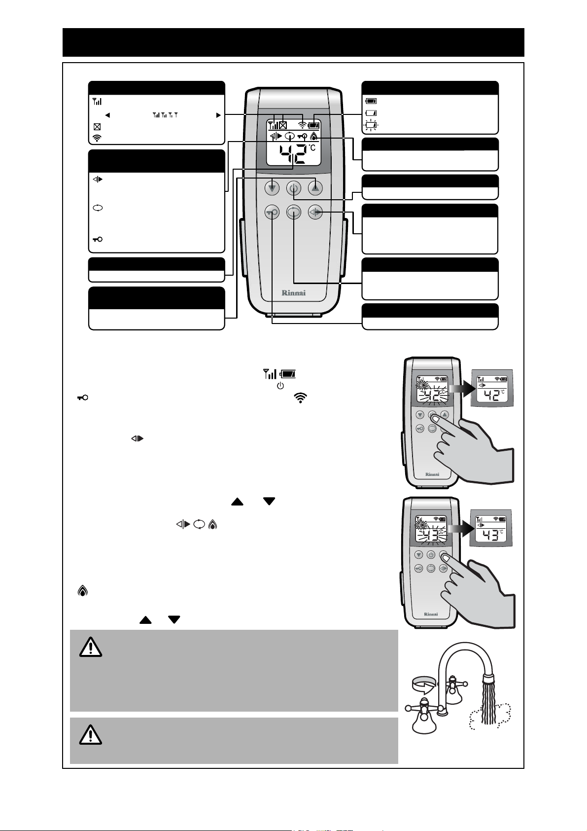
ABOUT THE WIRELESS WATER CONTROLLER (MC-503RC)
COMMUNICATIONS STATUS
Signal strength indicator
Strong signal Weak signal
Outofrangeindicator
Communications indicator
WATER CONTROLLER
STATUS INDICATORS
This indicator illuminate s when the water
controller is in control of water delivery
temperature.
This indicator illuminates when the
Smartstart® preheater (when fitted) has
been activated.
This Child Lockindicatorilluminates when
the child lock has been activated.
WATER TEMPERATURE INDICATOR
Indicates the selected hot water temperature.
WATER TEMPERATURE
UP AND DOWN BUTTONS
These buttons are used to select the water
temperature.
BATTERY STATUS
Full battery indicator.
Low battery indicator.
Replace battery indicator, when flashing.
WATER HEATER 'In Use' INDICATOR
Indicates that the water heater is in operation
and delivering hot water.
ON/OFF BUTTON
Used to switch the water heater on and off.
.
TRANSFER BUTTON
Used to transfer control priority between the
water controllers. The controller wit h priority
has command of the hot water delivery
temperature.
PREHEAT BUTTON
Usedtostart and stopthe Smartstart® preheat
unit (when fitted).
See Smartstart® Operation on page 6.
CHILD LOCK BUTTON
Used to switch Child Lock function on and off.
TURNING ON THE WATER HEATER.
When the water heater is in the ‘Off’ condition only the communications
and battery status indicators are displayed on the digital monitor.
To turn the water heater ‘On’, press the On/Off button once (if Child lock
is activated see page 4). The communications indicator will briefly
illuminate to confirm that a signal has been sent to the transceiver
connected to the water heater.
The transfer indicator and the water temperature display will flash until
communication between the controller and transceiver is complete. When
the display stops flashing the water heater is ready to supply hot water.
ADJUSTING TEMPERATURE
Simply press the 'hot water temp' or buttons until the required
temperature is displayed on th e digital monitor. The water temperature
and any active status indicator will flash until communication
between controller and transceiv er is complete. DO NOT open the hot
water tap until the flashing stops and the desired temperature is displayed.
To operate the water heater, open any hot water tap. This will
automatically light the burner, providing hot water. The ‘In Use’ indicator
will illuminate on the water controller.
Once the hot water is running, if the set temperature is either too hot or
cold press the or buttons until the desired temperature is reached.
Ready to use
Ready to use
Whilst hot water outlets are open the set t emperature may be
lowered to a minimum of 37°C. For safety, it cannot then be
NOTE
raised above 43°C until all hot water taps are closed.
If the water heater is turned ‘Off’ whilst hot water taps are
ON!ON!
COLDCOLD
open it can not be turned back ‘On’ until all hot water taps
have been closed.
Always check water temperature at the outlet before use.
CAUTION
A parent or carer should always check the temperature
before a child is placed in contact with h ot water, see page 1.
Rinnai Australia 3 Operation Manual
HOTHOT
Page 7

USING WIRELESS WATER CONTROLLERS
TRANSFERRING PRIORITY BETWEEN WATER CONTROLLERS
To control the water delivery temperatures when using two or more
controllers it is necessary to have priority transferred to the water
controller you wish to use.
An illuminated Transfer indicator confirms that the desired water
controller is in control of the water delivery temperature.
If the Transfer indicator is not illuminated press the ‘Transfer’
button to transfer priority to the desired water controller.
The Transfer indicator on the water controller will now illuminate to
indicating that priority has been transferred and that the water heater is
ready to supply hot water once a hot water tap is opened.
Whilst hot water taps are open transfer of 'prior ity' between controllers is not p ossible.
This is a safety feature.
NOTE
HOT WATER CONTROL
Temperatures higher than 50°C should only be able to be selected on the controller
labelled ‘Master’ controller (used in the kitchen), not on those labelled ‘Bathroom’
controllers. This helps minimise the risk of burns.
The wireless transceiver has been incorrectly assigned if temperatures in excess of
50°C are able to be selected on controllers used in bathrooms, ensuites, toilets and
laundries. Re-assign the wireless transceiver if this is the case. See “UN-ASSIGNING
AND RESETTING WIRELESS WATER CONTROLLERS” on page 14 and “INSTALLING
WIRELESS WATER CONTROLLERS” on page 13
USING CHILD LOCK FUNCTION
The Child Lock function is designed to prevent small children or the infirm
from operating the wireless controllers.
To Activate the Child Lock
To activate the Child Lock function press the button for 3 seconds. The
Child Lock indicator will illuminate to confirm that the function is now
active. Once activated only the initiating controller can then deactivate this
function?
To Deactivate the Child Lock
To deactivate the Child Lock function press the button for 3 seconds.
The Child Lock indicator will go out to show that the function is no
longer active.
Child lock only applies to the water controller initiating the function and can be
activated / de-activated regardless of priority status or whether the water heater is
NOTE
in the ‘On’ or ‘Off’ condition.
While the child lock is activated only the ‘Child Lock’ control and the ‘Off’
control are functional from that controller.
When the water heater is turned ‘Off’ while Child lock is activated it can not be turned
‘On’ again from a controller where the Child lock is activated.
If the water heater is turned ‘Off’ whilst hot water outlets are ope n it can no t b e t urn ed
back ‘On’ until all hot water outlets have been closed.
3 seconds
Child lock is de-activated during a battery change or when batteries fail.
Rinnai Australia 4 Operation Manual
Page 8

USING WIRELESS WATER CONTROLLERS
WIRELESS WATER CONTROLLERS BATTERIES
Wireless water controllers use 2 x
1.5V AAA batteries. The battery
symbol in the display monitor
indicates the remaining charge in
one of three levels.
To replace the batteries:
Before attempting to change the batteries first ensure that all moisture has been removed from the
water controller. Failure to do so may allow water to enter the water controller causing damage.
1. Remove the controller from the wall mounting bracket.
2. To open the battery compartmen t turn th e ba tt er y com p ar tm en t cover a full turn anti-clockwise.
3. Insert the batteries observing the correct polarity as shown on the rear of the controller.
4. To close the battery compartment align the " " and " " marks on the battery compartment
cover and the controller body. Then turn the battery compartment cover a full turn clockwise to
obtain the correct seal.
5. Return the controller to the wall mounting bracket.
1 532 4
Battery charge level OK.
Battery charge level is low.
Batteries need replacing (when flashing)
Turn battery
compartment
cover one full turn
anti-clockwise
to open
Insert batteries observing
the correct polarity as
indicated inside the
battery compa rtment
Align marks and
turn battery
compartment
cover one full turn
clockwise to
close
Use only 2 x 1.5V AAA alkaline batteries.
IMPORTANT
DO NOT
• mix old and new batteries.
• use different types of batteries at the same time.
• heat or expose to flame.
• take apart or short circuit.
• attempt to recharge alkaline batteries.
• use batteries if their covering has been damaged or peeled off.
Battery life is approximately 1 yea r.
• Dispose of used batteries according to the manufacturers instructions.
Remove batteries if the remote control is not going to be used for a long period. This
will help avoid damage from leaking batteries.
Rinnai Australia 5 Operation Manual
Page 9

SMARTSTART® PRE-HEAT OPERATION
ABOUT THE SMARTSTART® PRE-HEAT SYSTEM
1
2
5
6
7
3
4
PREHEAT BUTTON
Used to start and stop 'Smartstart ®'
preheater.
3
DIGITAL
MONITOR
2
PREHEAT INDICATOR
Indicates that 'Smartstart ®'
preheater is activated*
4
ON/OFF
BUTTON
8
1
5
7
Preheat Function
The “preheat” function works in conjunction with various Rinnai water heater models and the
separately installed and optional Rinnai “Smartstart®” module.
When the “preheat” function is activated and used in accordance with these instructions, water in the
pipework connected between the water heater and the hot water outlets in your house is warmed
before any outlets are opened. This results in water savings and added convenience.
TRANSFER
INDICATOR
WATER HEATER
'IN USE' INDICATOR
6
8
TEMPERATURE
BUTTONS
TRANSFER
BUTTON
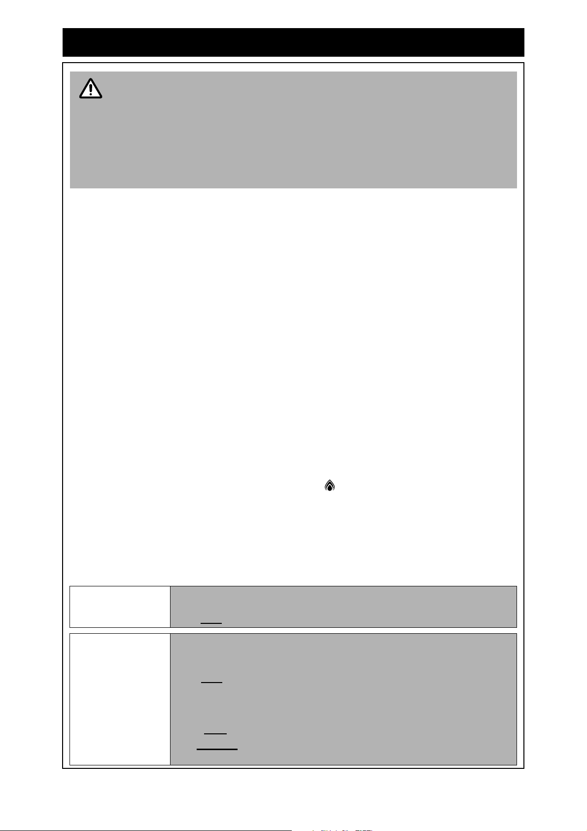
The preheat function is activated as follows:
1. Ensure that the hot water unit is on (temperature digits are displayed in the digital monitor ).
If more than one controller is fitted pre ss the ‘Transfer’ button to pass on priority to your
desired controller. The ‘Transfer’ indicator will illuminate to confirm that priority has been
assigned to this controller and that the hot water unit is ready to deliver hot water.
2. Select the desired temperature using the 'Temperature' buttons until the required
temperature is displayed in the digital monitor .
3. Press the ‘Preheat’ button once. The ‘preheat’ indicator and the ‘In Use’ indicator will
illuminate, signifying that the preheat system has been activated.
4. Wait approximately two minutes before opening an outlet. This will allow the water in the
pipework to be warmed.
The waiting time may be longer or shorter than two minutes depending on your
particular installation configuration.
NOTE
The preheat function is cancelled 5 minutes after activation and the ‘preheat’
indicator will go out. This is to conserve energy. To reactivate, simply repeat
steps 2-4 above.
* If the ‘preheat’ button is pressed and the ‘Smartstart®’ preheat unit is not
installed, the ‘preheat’ indicator will still light but there will be no preheat function.
The ‘preheat’ indicator will go out after a short time and will not affect the other
functions of the water controller or water heater.
1 2
5
3
8
6
7
3
Other Water Controller Functions
Water controller functions such as temperature control and transfer of priority between multiple
controllers are not affected by the operation of the preheat. Such functions are described in the
applicable sections of this manual.
Rinnai Australia 6 Operation Manual
Page 10

TROUBLESHOOTING
ERROR CODES
Your Rinnai Continuous Flow water heaters has a self diagnostic capability. If a fault occurs, an Error
Code will flash on the digital monitor of your water controllers. This assists with diagnosing the fault,
and may enable you to overcome a pr oblem witho ut a service call. Please quote the code displayed
when enquiring about service. *Status Monitor available on Infinity 26 (REU-VM2630WD), HD250e,
HD200e and HD200i models.
CODE FAULT REMEDY
Wireless water controller is ‘Out of Range’ due
to distance from transceiver or an obstruction.
-
03
10 Air intake or flue blocked. Service Call.
11 No ignition / No gas supply. Check gas is turned on at water heater and gas meter or cylinder.
12 Flame Failure / Low gas flow.
14 Remaining Flame Safety Device. Service Call.
16 Over Temperature Warning. Service Call.
32 Outgoing Water Temperature Sensor Faulty. Service Call.
33 Heat Exchanger Outlet Sensor Faulty. Service Call.
34 Combustion Air Temperature Sensor Faulty. Service Call.
52 Gas Modulating Valve Faulty. Service Call.
61 Combustion Fan Failure. Service Call.
65
Noticeable reduction in water flow. Inlet water filter needs to be cleaned. Service call.
Power interruption during Bath fill
(Water will not flow on power reinstatement).
Water Flow Control Faulty
(Does not stop flow properly).
Move wireless water controller or transceiver
or remove the obstruction.
Turn off all hot water taps. Press On/Off twice.
Check gas is turned on at water heater
and gas meter or cylinder.
Check there are no obstructions to the flue outlet.
Service Call.
71 Micro-processor Failure. Service Call.
72 Micro-processor Failure. Service Call.
LC
Scale build-up inside the heat exchanger.
Service Call.
In all cases, you may be able to clear the Error Code simply by turning the hot water tap OFF, then
ON again. If this does not clear the Error Code, try pushing the On/Off button OFF, then ON again. If
the Error Code still remains, contact Rinnai for advice.
No power display
When power to the water heater is disconnected the LCD of all wireless water
controllers will display as shown. Check that power is available, the water heater is
plugged in and that the power point is turned ‘on’.
Faults caused by insufficient gas supply, in sufficient water supply, ga s quality, water
quality, installation errors or operation errors are not covered by the Rinnai warran ty.
NOTE
Refer to the separate Warranty Conditions for full warranty details .
SERVICE
Wired and wireless water controllers, transceivers and water heaters do not contain user serviceable
parts and must only be serviced and repaired by an authorised person.
Rinnai has a Service and Spare Parts network with personnel who are fully trained and equipped to
give the best service on your Rinnai appliance. If your appliance requires service, ple ase call our Hot
Water Service Line. Rinnai recommends that this appliance be serviced every 3 years.
Rinnai Australia 7 Operation Manual
Page 11

INSTALLATION MANUAL
INSTALLATION GENERAL ........................................................................................9
RINNAI WIRELESS WATER CONTROLLERS .................................................................................. 9
GENERAL INSTALLATION INFORMATION ......................................................................................9
POSITIONING OF TRANSCEIVER AND WIRELESS WATER CONTROLLERS ............................ 10
COMMUNICATION CABLE ......................................................................................11
CONNECTING COMMUNICATION CABLES TO THE WATER HEATER ....................................... 11
TRANSCEIVER INSTALLATION..............................................................................12
MOUNTING THE TRANSCEIVER .................................................................................................... 12
CONNECTING COMMUNICATION CABLE TO THE WIRELESS TRANSCEIVER ........................ 12
SETTING THE MAXIMUM TEMPERATURE AT THE TRANSCEIVER ........................................... 12
WIRELESS WATER CONTROLLER INSTALLATION.............................................13
INSTALLING WIRELESS WATER CONTROLLERS .....................................................................13
INSTALLING MULTIPLE WIRELESS WATER CONTROLLERS .....................................................14
TROUBLE SHOOTING WIRELESS WATER CONTROLLERS CHANNEL ASSIGNMENT ............ 14
UN-ASSIGNING AND RESETTING WIRELESS WATER CONTROLLERS .................................... 14
INSTALLING WIRED AND WIRELESS WATER CONTROLLERS .................................................. 14
MOUNTING THE WIRELESS WATER CONTROLLER .................. .................................................15
Rinnai Australia 8 Installation Manual
Page 12

INSTALLATION GENERAL
RINNAI WIRELESS WATER CONTROLLERS
A wireless water controller installation utilises a 'transceiver' and up to 4 wireless water controllers.
Unlike most remote control systems, there is 'two way' communication between the transceiver and
controllers. The 'transceiver' is c onnected by electrical cable to the water he ater. The 'transceiver'
transmits control signals received from the wireless controllers operated by the user to the water
heater. The 'transceiver' transmits operational 'status' signals from the water heater which are
received by individual wireless controllers to ensure controller displays reflect the operational status
of the water heater.
Wireless water controllers can be installed in conjunction with Universal and Deluxe wired water
controllers and will function as described in the Operation Section of this manual. Refer to page 2 to
confirm the maximum number and combin at ion of wat er con tro lle rs th at can be fitte d.
Master and Sub controllers and temperatures
Only one wireless or wired controller can be designated the 'Master Controller' (MC). This controller
is normally used in the kitchen and usually has a maximum temperature of 55°C, is sufficient for
almost all kitchen applications. Temperatures higher than 55 °C are possible bu t usually unnecessary
and will result in higher gas use and increase the risk of burns. Some conditions regarding Master
Controller maximum temperatures are as follows:
• Temperatures of 55°C or higher can only be selected on the controller designated as Master
Controller (MC) if the transceiver 'Max Temp' is also programmed to 55°C or higher.
• The temperature of hot water delivered is always limited to th e maximum temperatur e programmed
into the water heater itself. For example, if the transceiver maximu m temperature is programmed to
55°C and the water heater is limited to 50°C, the maximum temperature that the water heater will
deliver is 50°C. In this case 55°C will be displayed on the wireless Master Controller until a tap is
opened after which the display will revert to 50°C.
The water heater maximum temperature cannot be adjusted by the user.
IMPORTANT
These adjustments can only be carried out by a qualified and licensed trades person.
The remaining controllers are designated 'sub' controllers and are for use in bathrooms, toilets and
laundries. The temperature limit for all 'Sub' controllers is always 50°C to minimise the risk of burns in
these areas.
Adhesive labels are included for individual identification of wireless controllers as master (Kitchen) or
sub (Bathroom No.) controllers. These labels are usu ally placed on the top back of the wireless wate r
controller body.
Other manufacturers water controllers are NOT compatible with Rinnai water heaters.
Water controllers MUST NOT be used with any Solar Boost wate r heater. Rinn ai water
NOTE
controllers brought in from other countries are not compatible with Rinnai appliances
sold in Australia.
GENERAL INSTALLATION INFORMATION
Rinnai Wireless Transceivers can be connected to the water heater models listed on the cover page
by the end user in accordance with these Instructions. These water heaters contain the ’Ezi connect’
cable connector and a qualified tradesperson is not required.
Rinnai Wireless Transceivers are also compatible with some older water heater models not listed on
the cover page of these Instructions. Since older water heater mode ls do not contain the 'Ezi connect'
cable connector, wireless water controllers must be installed and commissioned by a suitably qualified
and licensed tradesperson. Contact Rinnai for information regarding compatibility with older water
heaters.
Regardless of water controller installation, all Rinnai water heaters must only be
installed by an Authorised person.
IMPORTANT
Water controllers, transceivers and water heaters do not contain user serviceable
parts and must only be serviced and repaired by an authorised person.
Rinnai Australia 9 Installation Manual
Page 13

INSTALLATION GENERAL
POSITIONING OF TRANSCEIVER AND WIRELESS WATER CONTROLLERS
The water controllers must be installed in shaded and clean locations. The water controllers and the
transceiver should be fitted out of reach of children (suggested height from floor to be at least 1500
mm).
The water controllers are water resistant, however, durability is improved when positioned outside the
shower recess. The water controllers must be installed at least 400 mm above the highest part of a
sink, basin or bath.
The MC-503RC Wireless water controller is a water resistant device, however
excessive exposure to water such as immersion may result in damage to the
NOTE
controller.
• DO NOT immerse the controller into water.
• AVOID direct exposure to water or steam as these conditions may cause a
malfunction.
• ALWAYS AVOID exposure to water when the battery compartment is open.
When cleaning your water controller use ONLY a damp cloth and a mild detergent.
The transceiver comes supplied with a 1.5m leng th of comm u nica tio n s cab le.
The transceiver’s antenna is located in the top. For the best results mount the transceiver so the top
of the transceiver is higher than the top of the water heater. If the transceiver is mounted to the side
or below the water heater signal strength may be reduced.
The transceiver may be mounted inside metal recess boxes or pipe covers, however this may also
reduce signal strength.
In some cases building construction and d esi gn can re duce signal st reng th an d it may be ne cessa ry
to locate the transceiver in a central location inside the building. For such conditions extended length s
of communication cable are available from Rinnai.
Alternatively two core sheathed (double insulated) flex with minimum crosssectional
area of 0.5 mm² may be used. Maximum individual cable runs should not exceed 20m.
NOTE
Take the signal strength into consideration when determinig the best location for both the transceiver
and the wireless water controllers.
Rinnai Australia 10 Installation Manual
Page 14

COMMUNICATION CABLE
CONNECTING COMMUNICATION CABLES TO THE WATER HEATER
Communication cables connect the water heater to any wired water controllers and the wireless
transceiver and operate at an extra low voltage (12 Volts DC) which is supplied from the water heater.
Communication cables are supplied with the wired controllers (15m) and the transceiver (1.5m) and
are fitted with spade terminals for connection to water heater. Up to two cables can be connected
directly to the ‘Ezi connect’ cable connector at the water heater. Extension cables are available from
Rinnai. Alternatively, two core sheathed (double insulated) flex with minimum cross sectional area of
0.5mm² may be used. Cable lengths must not exceed 20 metres.
DO NOT attempt to connect cables to the 'Ezi connect' cable connector at the water
CAUTION
To connect up to two cables to the ’Ezi connect’ cable connector
1. Isolate the electric power supply by switching the power point off and removing the power plug of
heater unless the electric power to the water heater is switched ‘off’ otherwise damage
to electrical components may occur.
If your water heater is not fitted with an 'Ezi connect' cable connector, installation
must be completed by a qualified and licensed tradesperson.
the water heater from the electric power socket.
2. Remove the retaining screw of the 'Ezi connect' cable connector at the base of the appliance.
A
3. Swing the 'Ezi connect' ca ble connector do or op en and thr ead the cable through the weather se al
of the cable access hole in the direction shown allowing sufficient cable length so that the
sheath of the cable can be secured with cable clamp supplied with the transceiver.
4. Loosen screw terminals and and connect the cable spade connectors to these terminals
B
C
D E
and re-tighten. Polarity is not important, either wire colour can be connected to either terminal.
5. Return the 'Ezi connect' cable connector to the original position taking care not to damage cable
wires in the process and replace the retaining screw .
A
A
A
B
B
D
C
E
'Ezi connect' cable connector f o r water heater models:
INFINITY 26, 26 Plus, 20, 16, V1500, V1200.
HD 200e (REU-VM2630WC).
To connect three or four cables to the 'Ezi connect' cable connector, consult the
“CONNECTING WATER CONTROLLERS” section of the water heater Operation /
NOTE
Installation manual supplied with the water heater.
Rinnai Australia 11 Installation Manual
'Ezi connect' cable connector f o r water heater models:
INFINITY 32, 26i, EVIROSMART
HD 250e, 200e (REU-VRM2632WC), 200i
Page 15

TRANSCEIVER INSTALLATION
MOUNTING THE TRANSCEIVER
• The distance between the water heater and the transceiver must not exceed 20m.
• Metallic structures, appliances or magnetic fields in the vicinity of transceiver or
NOTE
wireless water controllers may reduce signal strength.
• Do not install transceiver near a heat source, such as a cook t op, stove or oven. Heat,
steam, smoke and hot oil may cause damage.
• The transceiver MUST NOT be installed where chemicals such as benzine, alcohol,
turpentine, hydrogen sulphide, ammonia, chlorine or similar chemicals are in use.
1. Determ ine th e most su itable position for th e transceiver (see “POSITIONING
OF TRANSCEIVER AND WIRELESS WATER CONTROLLERS” on
35
58
25
page 10).
2. The tr ansceiver can be mounted to the wall using suitable screws or mounted
to the side of the water heater via the strip of adhesive tape glued to the back
of the receiver case.
3. If the transceiver is to be wall mounted, use the screws and/or anchors
provided. Avoid over-tightening of fixings as this may cause damage. DO
NOT use powered tools to tighten fittings
4. If the transceiver is to be mounted to the side of the water heater perform the following steps:
a. Clean the side of the water heater where the transceiver is g oing to b e mo unted using a clea n
rag with some methylated spirits or alcohol.
b. Remove the paper strip from the adhesive tape glued to the back of the receiver case to expose
the adhesive surface.
c. Push the adhesive surface to the side of the water heater in the desired location. Press the
receiver into the side of the water heater for a couple of second s to allow the ad hesive to bind.
CONNECTING COMMUNICATION CABLE TO THE WIRELESS TRANSCEIVER
1. With the electric power supply still isolated,
Controllers
Controllers
unscrew the transceiver access cover to reveal
control keypad and terminals.
No. 1 No. 2 No. 3
MC
No. 1 No. 2 No. 3
MC
157
167
2. Thread the transceiver cable through the cable
clamp , allowing sufficient cable length so that
E
the sheath of the cable can be secured.
3. Loosen screws terminals and of the
F G
transceiver and connect the spade connectors of
the cable to these terminals and re-tighten.
Polarity is not important, either wire colour can be
E
connected to either terminal.
SETTING THE MAXIMUM TEMPERATURE AT THE TRANSCEIVER
1. Ensure the power to the water heater is switched ‘on’.
2. Set the transceiver’s maximum water temperature to 55°C by pressing
the ‘Max Temp’ button until 55 is displayed.
Refer to “Master and Sub controllers and temperatures” on page 9 for information
regarding using of the maximum temperatures with wireless water controllers.
NOTE
F
G
Max Temp. M aimtena nce
Tem p. Vol ume
Rinnai Australia 12 Installation Manual
Page 16

WIRELESS WATER CONTROLLER INSTALLATION
INSTALLING WIRELESS WATER CONTROLLERS
This installation procedure applies to wireless water controller installations only. For
IMPORTANT
combined wired and wireless water controller installations refer to “INSTALLING
WIRED AND WIRELESS WATER CONTROLLERS” on page 14.
Up to 4 wireless water controllers can be installed. Only one of these can be
designated as a 'Master Controller' (MC), others will be de signated as 'Sub' controllers.
Only one wireless water controller can be installed at a time. DO NOT insert batteries
until step 3.
1. Ensure the power to the water heater is switched ‘on’.
2. Press the ‘Entry’ button on the transceiver for approximately 2
a
seconds to select a wireless controller channel for tuning. The first
unassigned wireless controller channel LED will begin a fast flash,
a
EntryEntry
Controllers
No. 1 No. 2 No. 3
MC
signifying that this channel has been selected for tuning.
The default order of channel selection is as follows:
The wireless Master Controller is the only wireless controller capable of selecting
NOTE
maximum delivery Temperatures exceeding 50°C. Ensure that the Master Controller
(Kitchen) label provided is placed on the top rear of the assigned controller.
3. Select a wireless water controller for tuning to the
unassigned transceiver channel and remove the
Full turn
anti-clockwise
Full turn
clockwise
controller from it’s wall mounting bracket. Open
the battery compartment with a full turn anti-
b
clockwise. Insert the batteries observing the
correct polarity. Close the battery compartment
with a full turn clockwise
b
turn to open
turn to close
4. After battery installation the wir eless controller will momentarily display an initialisation screen (A),
which will then switch to screen (B) or (C).
5. If screen (B) is displayed press and hold the ‘On/Off’ button until screen (C) is displayed. This
takes approximately 2 seconds.
6. From screen (C) press the ‘On/Off’ button once to start the tuning process which will take
approximately 5 seconds. Once the controller is tuned the controller channel LED on the
transceiver will become steady and the controller LCD will switch to screen (D) or (E).
7. From screen (D) press the ‘On/Off’ button once or from screen (E) press the ‘Transfer’
button once to complete the tuning of this channel. At this point screen (F) will be displayed by the
controller. The wireless water controller is now tuned and rea dy to control the delivery temperature
of the water heater.
8. Apply one of the se lf-adhesive id entification stickers to the rear of th e controlle r, ensuri ng that the
Master Controller sticker is only applied to the wireless water controller tuned to channel MC.
(B) (D)
(A)
Press for
approximately
3 seconds
(C)
Press once
OR
(F)
(E)
Press once
to start the tuning
OR
Rinnai Australia 13 Installation Manual
process, this takes
approximately
5 seconds
Press once
Page 17

WIRELESS WATER CONTROLLER INSTALLATION
e
INSTALLING MULTIPLE WIRELESS WATER CONTROLLERS
To install subsequent wireless water controllers repeat steps 2 to 8 for each additional wireless wa ter
controller.
Once all wireless water controllers are installed re-secure the transceiver ac ces s c ov er.
TROUBLE SHOOTING WIRELESS WATER CONTROLLERS CHANNEL ASSIGNMENT
If at the end of the installation process screen (C) is
displayed do the following:
Confirm first that the power is still on at the water
heater.
If power is off turn it back on. If the channel has been
correctly assigned then the display should show
either screens (E), (F) or (G).
If screen (C) is still displayed un-install
and reset the wireless controller and
NOTE
repeat the installation procedure.
UN-ASSIGNING AND RESETTING WIRELESS WATER CONTROLLERS
1. Press the desired controller channel button .
The LED will go out to signify that this channel is
c
c
No. 1 No. 2 No. 3
MC
now un-assigned.
(C)
(F) (G)(E)
d
2. Removing the batteries from the wireless
d
controller will reset the wireless controller and
complete the un-install process.
INSTALLING WIRED AND WIRELESS WATER CONTROLLERS
When installing combinations of both wired and wireless controllers, all wired water
IMPORTANT
controllers MUST BE connected before the wireless water controllers are assigned to
a transceiver channel.
Refer to page 1 to confirm the maximum number and combination of water controllers
that can be fitted
Wired water controllers can ONLY be added to an existing wireless installation when:
• All wireless transceiver channels have been un-assigned.
• All wireless controllers have been reset.
See “UN-ASSIGNING AND RESETTING WIRELESS WATER CONTROLLERS” above.
When the wireless transceiver is installed it automatically detects any wired
water controllers already connected to the water heater.
The LEDs of the channels assigned to wired controllers will slow flash.
The channels for wired water controllers are assigned in sequence as
follows:
MC100V or MC91 (programmed as a Master Controller) will automatically
be assigned to the MC channel.
BC100V or MC91 (not programmed as a Master Controller) will
automatically be assigned to an available channel other than the MC
channel.
Install the wireless water controllers to any of the unassigned channels
following steps 1 to 9 on page 13.
Rinnai Australia 14 Installation Manual
Page 18

WIRELESS WATER CONTROLLER INSTALLATION
MOUNTING THE WIRELESS WATER CONTROLLER
• Metallic structures, appliances or magnetic fields in the vicinity of transceiver or
NOTE
1. Determine the most suitable position for the water controller (see “POSITIONING OF
wireless water controllers may reduce signal strength.
• Do not install wireless water controllers near a heat source, s uch as a cook top, stove
or oven. Heat, steam, smoke and hot oil may cause damage.
• Do not install wireless water controllers in direct sunlight.
• Do not install wireless water controllers outdoors unless protection from dust
ingress and sunlight are provided.
• Wireless water controllers MUST NOT be installed where chemicals s uch as benzine,
alcohol, turpentine, hydrogen sulphide, ammonia, chlorine or other similar chemicals
are in use.
TRANSCEIVER AND WIRELESS WATER CONTROLLERS” on page 7).
The ‘Signal Strength’ indicator displays one of four levels.
Strong Weak
The ‘Out Of Range’ indicator displays when the wireless water controller is out of range of the
transceiver or when an object is obstructing the radio signal.
Wireless water controllers should be positioned such that the signal strength indicator displays at
least ‘2 bars’ next to the antenna symbol during installation. Signal strength varies with
atmospheric and other conditions. If the signal strength is weaker than ‘2 bars’ during installation,
there may be other times when the signal is too weak to allow operation.
2. Slide the wireless water controller from its’ wall mounting bracket.
3. Use the wall mounting bracket as a template to mark off and drill 2 holes for use with mounting
fixings.
4. Secure th e wall mounting bracket to the wall with the screws and or anchors provided. Avoid over tightening of fixings as this may cause damage. DO NOT use powered tools to tighten fixings.
5. Slide the wireless water controller back into its’ wall mounting bracket.
81.7
142
31.5
13.8
66.6
28
ADDITIONAL WATER CONTROLLER MOUNTING CONSIDERATIONS.
The MC-503RC uses a Liquid Crystal Display (LCD) for the digital
NOTE
monitor. Light reflections can make the LCD difficult to see at direct
eye level.
For best results when Installing the MC-503RC mount the remote
controller lower than your eye-level to avoid these light reflectio ns.
Rinnai Australia 15 Installation Manual
Page 19

NOTES
Rinnai Australia 16 Installation Manual
Page 20

CONTACT INFORMATION
Australia Pty. Ltd.
ABN 74 005 138 769
Head Office
10-11 Walker Street,
Braeside, Victoria 3195
P.O. Box 460
Tel: (03) 9271 6625
Fax: (03) 9271 6622
Rinnai has a Service and Spare Parts network with personnel who are fully trained
and equipped to give the best service on your Rinnai appliance. If your appliance
requires service, please call our Hot Water Service Line. Rinnai recommends that
this appliance be serviced every 3 years.
17 RA TSD 08-002 Issue 3 12/08
Internet: www.rinnai.com.au E-mail: enquiry@rinnai.com.au
National Help Lines
Sales & Service
Tel: 1300 555 545* Fax: 1300 555 545*
Spare Parts & T
Tel: 1300 366 388* Fax: 1300 300 141*
*Cost of a local call Higher from mobile or public phones.
Hot Water Service Line
Tel: 1800 000 340
U284-1520×01(00)
㪇㪍㪇㩷㪇㪇㪇㪈㪉㩷㪌㪏㪈㪌㪉㩷㪉
echnical Info
Printed in Japan 2008.12
 Loading...