

Page 1
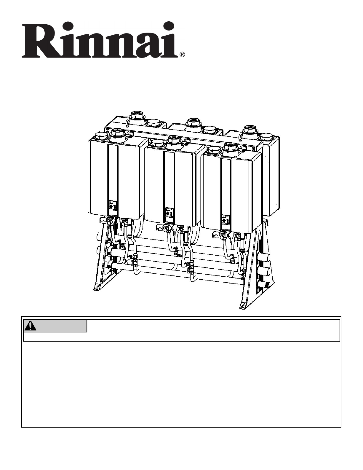
Tankless Rack System (TRS) Installaon Manual
Additional information can be obtained from the appliance manual.
Free Standing Rack
(6 water heaters)
WARNING
— Do not store or use gasoline or other ammable vapors and liquids in the vicinity of this or any other
appliance.
— WHAT TO DO IF YOU SMELL GAS
Do not try to light any appliance.
Do not touch any electrical switch; do not use any phone in your building.
Immediately call your gas supplier from a neighbor’s phone. Follow the gas supplier’s instrucons.
If you cannot reach your gas supplier, call the re department.
— Installaon and service must be performed by a licensed professional.
1 Rinnai Rack Installation
If the informaon in these instrucons is not followed exactly, a re or explosion
may result causing property damage, personal injury or death.
Page 2

Notes
2 Rinnai Rack Installation
Page 3
Table of Contents
Description ............................................................ 4
Venting Options ..................................................... 4
TRS Part Nos. and Main Components .................. 5
Specifications ................................................... 7-18
Clearances .......................................................... 19
Hoisting ............................................................... 20
Securing Racks .............................................. 21-23
Relief Valve Piping .............................................. 24
Piping for Multiple Racks ..................................... 24
Parallel Piping Drawing ....................................... 25
End caps / Connections ....................................... 26
Condensate Drain ................................................ 27
Checklist for Plumbing ......................................... 27
Installation of Gas Supply .................................... 28
Connecting Electricity .......................................... 28
MSB Installation ............................................. 29-30
Final Checklist ..................................................... 31
Replacement Parts ........................................ 32-33
Extended Limited Labor Warranty ................. 34-35
Safety Symbols
This is the safety alert symbol. This symbol alerts you to potential hazards that can kill or hurt you and
others.
DANGER
WARNING
CAUTION
Installaon
A licensed professional must install the (TRS) Tankless Rack System
The installer should have skills such as
connecng gas lines, water lines, valves, and electricity
knowledge of applicable naonal, state, and local codes
If you lack these skills, contact a licensed professional.
Indicates an imminently hazardous situation which, if not avoided, will result in death or
serious injury.
Indicates a potentially hazardous situation which, if not avoided, could result in death or
serious injury.
Indicates a potentially hazardous situation which, if not avoided, could result in minor or
moderate injury. It may also be used to alert against unsafe practices.
3 Rinnai Rack Installation
Page 4
Descripon
Rinnai Tankless Rack Systems (TRS) include wall mounted and free standing conguraons. The wall mounted
rack systems are available for 2 or 3 water heaters. Free standing rack systems are available for 2, 3, 4, 5, or 6
water heaters.
The TRS can be ordered with Rinnai’s Common Venng System, which consists of the CVent exhaust venng and
PP or PVC intake venng. Up to eight tankless units can share the same CVent system.
The Rinnai TRS features design details that make installaon simple and straighorward.
• Maneuverability: Fits, fully assembled, through standard 32-inch doorways and on elevators
• Flexibility: Available in both wall-mount or freestanding design for indoor and outdoor installaons.
• Preassembled Gas and water manifolds are properly sized to maintain opmum performance.
• The racks are constructed of powder-coated aluminum, powder coated steel, and stainless to stand up to the
most demanding commercial environments, while minimizing weight.
• Oponal electronic controls to obtain turn down raos of up to 327:1 (Sold Separately).
NOTE: The TRS is designed to be used with Rinnai tankless water heaters only. Do not mount non-Rinnai water
heaters on the TRS.
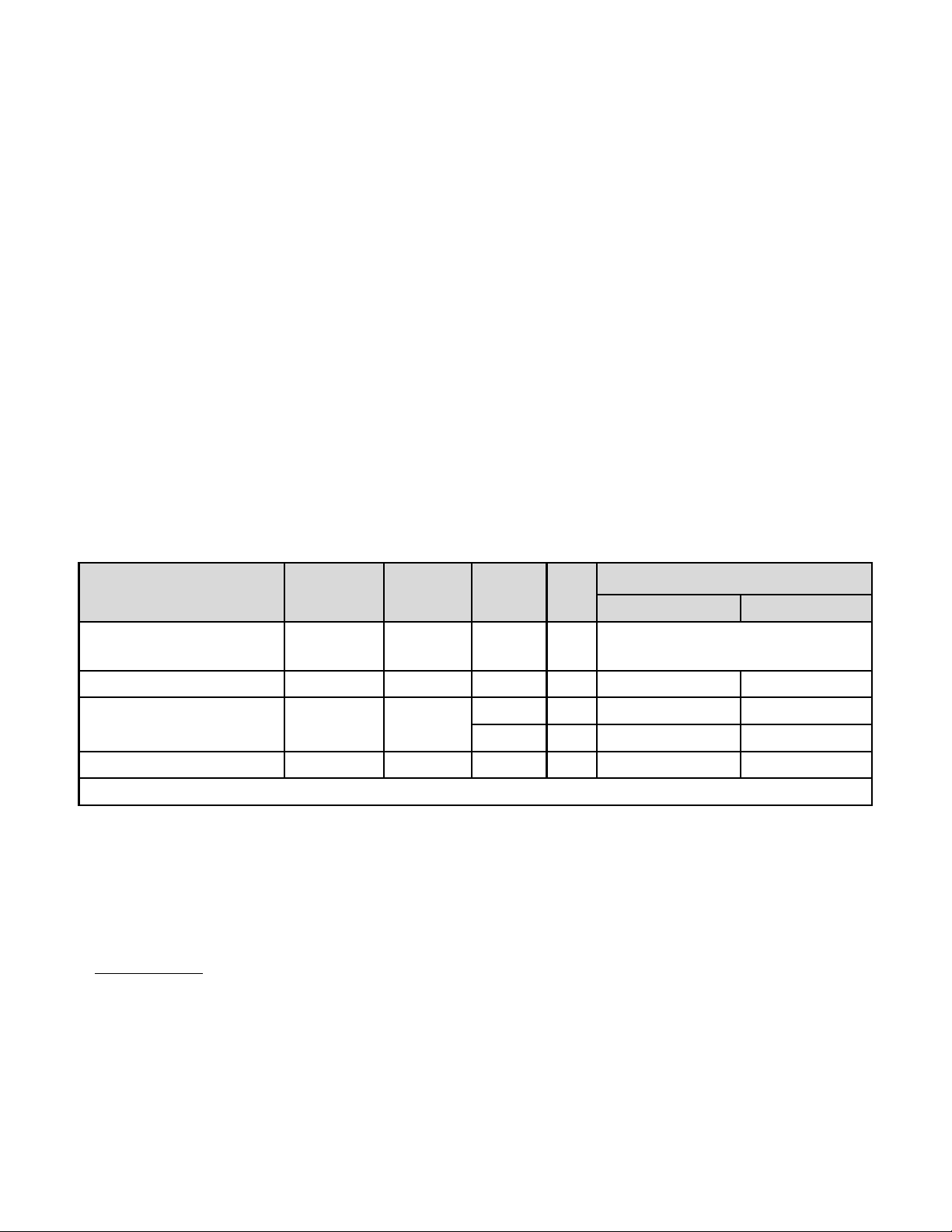
Venng Opons
Venng Opons
Common Venng System *
Concentric PPs PVC 5" 1 65’ 45’
Twin Pipe PVC/CPVC PVC/CPVC
Dual Pipe* PPs PPs or PVC 3" 1 41' 41
* This venng is provided by Centrotherm through their own distribuon network
Exhaust Vent
Material
PPtl, PPs
Intake Vent
Material
PVC, PPtl,
PPS
PVC/CPVC
Diameter
8" 8 100' (with 7 units) or 41’ (with 8 units)
4” 1 100’ 65’
3” 1 65’ 41’
Max.
Units
Max. Vent Length
Natural Gas Propane
• Refer to the water heater installaon and operaon manual for specic details regarding vent installaon
opon and installaon.
• Venng components are packaged separately from the pre-assembled Rack for eld assembly of the vent
system by the contractor.
* Only the C199i is cered for both direct vent and exhaust only with room air (exhaust must terminate
vercally in room air applicaon) when installed in a commercial common vent applicaon only. Reference
Rinnai Common Vent (CVent) Manual for further informaon.
4 Rinnai Rack Installation
Page 5
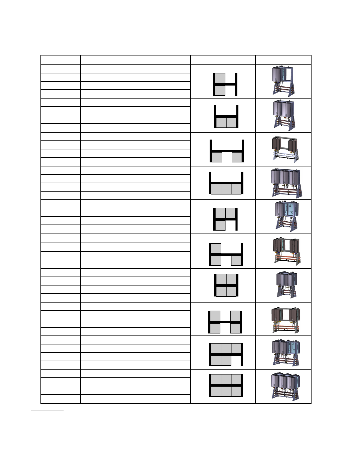
TRS Part Nos. and Main Components
Tankless Rack WALL HANGING
Part No.* Rack type Configuration Illustration
TRW02iN 2-unit interior wall hanging rack, NG
TRW02eN 2-unit exterior wall hanging rack, NG
TRW02iP 2-unit interior wall hanging rack, LP
TRW02eP 2-unit exterior wall hanging rack, LP
TRW23iN 2-unit interior wall hanging rack, NG
TRW23eN 2-unit exterior wall hanging rack, NG
TRW23iP 2-unit interior wall hanging rack, LP
TRW23eP 2-unit exterior wall hanging rack, LP
TRW03iN 3-unit interior wall hanging rack, NG
TRW03eN 3-unit exterior wall hanging rack, NG
TRW03iP 3-unit interior wall hanging rack, LP
TRW03eP 3-unit exterior wall hanging rack, LP
Tankless Rack INLINE WALL MOUNT
Part No.* Rack type Configuration Illustration
TRS02ILWiN 2-unit interior wall mount rack, NG
TRS02ILWeN 2-unit exterior wall mount rack, NG
TRS02ILWiP 2-unit interior wall mount rack, LP
TRS02ILWeP 2-unit exterior wall mount rack, LP
TRS23ILWiN 2-unit interior wall mount rack, NG
TRS23ILWeN 2-unit exterior wall mount rack, NG
TRS23ILWiP 2-unit interior wall mount rack, LP
TRS23ILWeP 2-unit exterior wall mount rack, LP
TRS03ILWiN 3-unit interior wall mount rack, NG
TRS03ILWeN 3-unit exterior wall mount rack, NG
TRS03ILWiP 3-unit interior wall mount rack, LP
TRS03ILWeP 3-unit exterior wall mount rack, LP
Part no. system: TR = tankless rack; W = wall hanging;S = stand alone; IL = inline; ILW = Inline Wall Mount; 2/3/4/5/6 = no. of water
heaters; i/e = interior/exterior; NG/LP = fuel type
5 Rinnai Rack Installation
Page 6
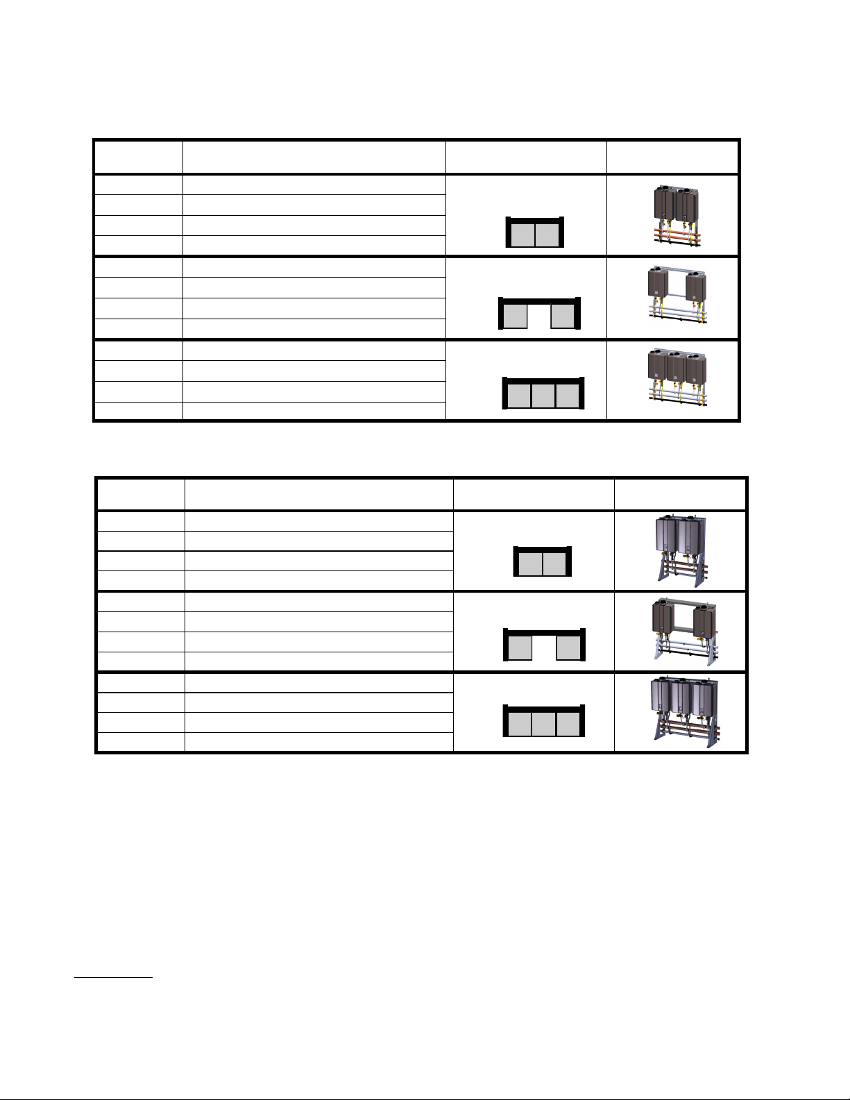
TRS Part Nos. and Main Components
Tankless Rack FREESTANDING
Part No.* Rack type Configuration Illustration
TRS02iN 2-unit interior free standing rack, NG
TRS02eN 2-unit exterior free standing rack, NG
TRS02iP 2-unit interior free standing rack, LP
TRS02eP 2-unit exterior free standing rack, LP
TRS02ILiN 2-unit INLINE interior free standing rack, NG
TRS02ILeN 2-unit INLINE exterior free standing rack, NG
TRS02ILiP 2-unit INLINE interior free standing rack, LP
TRS02ILeP 2-unit INLINE exterior free standing rack, LP
TRS23ILiN 2-unit INLINE interior free standing rack, NG
TRS23ILeN 2-unit INLINE exterior free standing rack, NG
TRS23ILiP 2-unit INLINE interior free standing rack, LP
TRS23ILeP 2-unit INLINE exterior free standing rack, LP
TRS03ILiN 3-unit INLINE interior free standing rack, NG
TRS03ILeN 3-unit INLINE exterior free standing rack, NG
TRS03ILiP 3-unit INLINE interior free standing rack, LP
TRS03ILeP 3-unit INLINE exterior free standing rack, LP
TRS03iN 3-unit interior free standing rack, NG
TRS03eN 3-unit exterior free standing rack, NG
TRS03iP 3-unit interior free standing rack, LP
TRS03eP 3-unit exterior free standing rack, LP
TRS36iN 3-unit interior free standing rack, NG
TRS36eN 3-unit exterior free standing rack, NG
TRS36iP 3-unit interior free standing rack, LP
TRS36eP 3-unit exterior free standing rack, LP
TRS04iN 4-unit interior free standing rack, NG
TRS04eN 4-unit exterior free standing rack, NG
TRS04iP 4-unit interior free standing rack, LP
TRS04eP 4-unit exterior free standing rack, LP
TRS46iN 4-unit interior free standing rack, NG
TRS46eN 4-unit exterior free standing rack, NG
TRS46iP 4-unit interior free standing rack, LP
TRS46eP 4-unit exterior free standing rack, LP
TRS05iN 5-unit interior free standing rack, NG
TRS05eN 5-unit exterior free standing rack, NG
TRS05iP 5-unit interior free standing rack, LP
TRS05eP 5-unit exterior free standing rack, LP
TRS06iN 6-unit interior free standing rack, NG
TRS06eN 6-unit exterior free standing rack, NG
TRS06iP 6-unit interior free standing rack, LP
TRS06eP 6-unit exterior free standing rack, LP
Part no. system: TR = tankless rack; W = wall hanging; S = stand alone; IL = inline; ILW = Inline Wall Mount; 2/3/4/5/6 = no. of water
heaters; i/e = interior/exterior; NG/LP = fuel type
Back
to
Back
6 Rinnai Rack Installation
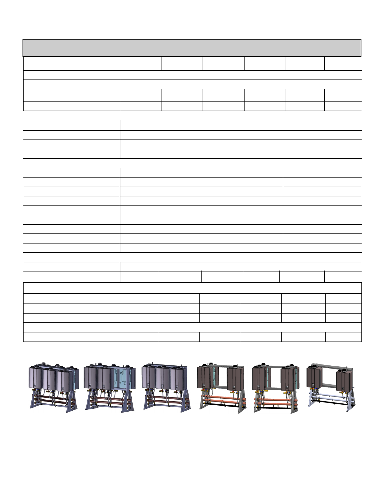
Page 7
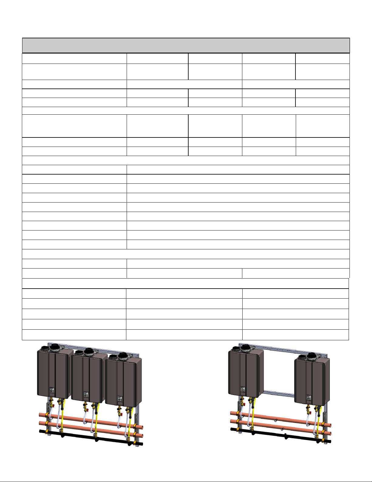
Specicaons
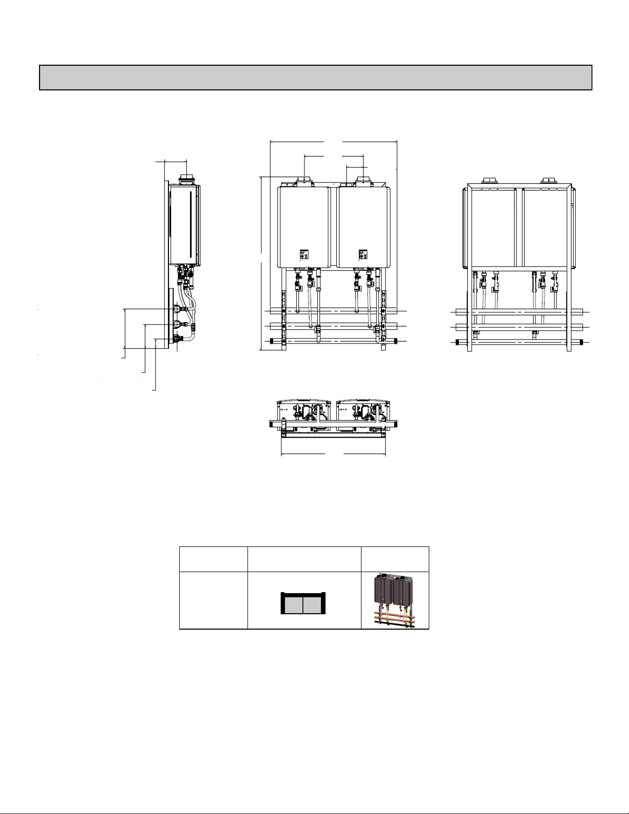
2 UNIT WALL HANGING FRAME
12.88 HOT (2”COPPER)
7.88 COLD (2”COPPER)
3.00 GAS (1-1/4”NPT)
LEFT
7.76
56.82
FRONT
44.00
20.50
5.92 TYP.
BACK
TRW02
Configuration Illustration Model
36.00
BOTTOM
7 Rinnai Rack Installation
Page 8
Specicaons
2 UNIT WALL HANGING FRAME
Model
Water Heater Model RUC98i, C199i (NG/LP) RU98e, C199e (NG/LP)
Crate Dimensions (HxLxD) - in 62 x 55 x 36
Weight - Fully Assembled - lbs 166 165
Weight - Shipping (total) - lbs 380 379
Rack Frame - Specifications
TRW02i TRW02e
Frame Material
Frame Finish Powder Coat Stainless
Color Gray Stainless
Water & Gas Connections
Hot Water Trunk Line Diameter 2"
Cold Water Trunk Line Diameter 2"
Hot Water Trunk Line Material Rigid Copper
Cold Water Trunk Line Material Rigid Copper
Water Trunk Connection Type 2" PIPE
Gas Trunk Line Diameter 1-1/4"
Gas Trunk Connection Type 1-1/4” MNPT
Gas Trunk Line Material Sch 40 Steel
Gas Branch Line Material PVC Over CSST
Electric Requirements
Voltage AC 120 Volts—60 Hz
Maximum Current (Amperes) 8
BTU and Flow Rates for RU98i, RUC98i, C199i, RU98e, C199e (NG/LP)
Number of Tankless Water Heaters 2
Flow rate @ 70°F rise (gpm) 10.8
Flow rate @ 100°F rise (gpm) 7.6
Minimum input rate (Btuh) 15,200
Maximum input rate (Btuh) 398,000
14 Gauge Hot Rolled Steel 1.5” Square
Tube 16 Gauge Stainless Steel 1.5” Square Tube
TRW02
8 Rinnai Rack Installation
Page 9
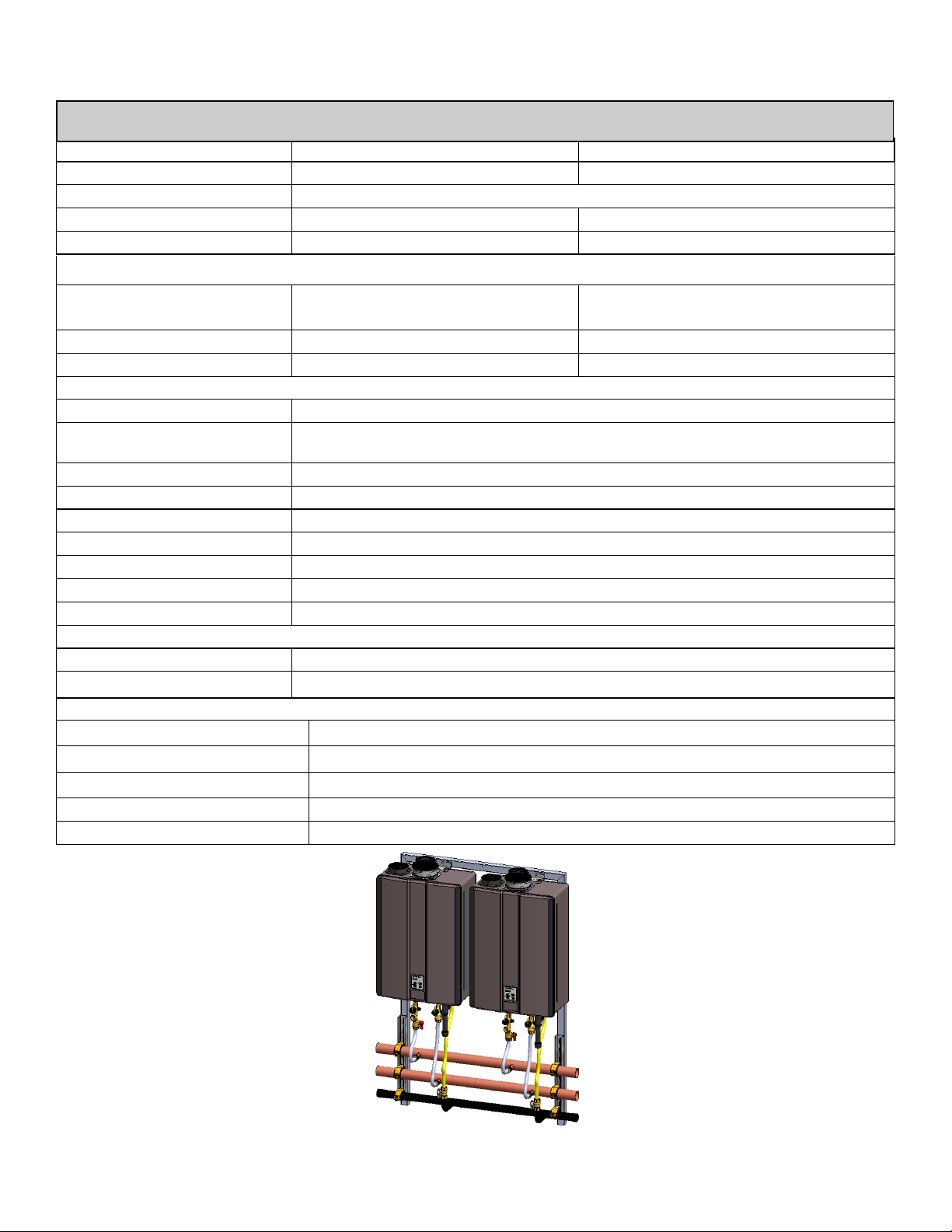
Specicaons
3 UNIT WALL HANGING FRAME
12.88 HOT (2”COPPER)
7.88 COLD (2”COPPER)
3.00 GAS (1-1/4”NPT)
LEFT
7.76
56.82
FRONT
62.00
41.00
5.92 TYP.
54.50
BACK
BOTTOM
Configuration Model Illustration
TRW03
TRW23
9 Rinnai Rack Installation
Page 10
Specicaons
3 UNIT WALL HANGING FRAME
Model TRW03i TRW03e TRW23i TRW23e
Water Heater Model
Crate Dimensions (HxLxD) - in 62 x 75 x 36 62 x 75 x 36
Weight - Fully Assembled - lbs 244 240 182 179
Weight - Shipping (total) - lbs 458 454 396 393
Rack Frame - Specifications
Frame Material
Frame Finish
Color
Water & Gas Connections
Hot Water Trunk Line Diameter 2"
Cold Water Trunk Line Diameter 2"
Hot Water Trunk Line Material Rigid Copper
Cold Water Trunk Line Material Rigid Copper
Water Trunk Connection Type 2" PIPE
Gas Trunk Line Diameter 1-1/4"
Gas Trunk Connection Type 1-1/4” MNPT
Gas Trunk Line Material Sch 40 Steel
Gas Branch Line Material PVC Over CSST
Electric Requirements
Voltage AC 120 Volts—60 Hz
Maximum Current (Amperes) 12 8
BTU and Flow Rates for RU98i, RUC98i, C199i, RU98e, C199e (NG/LP)
Number of Tankless Water Heaters 3 2
RU98i, RUC98i,
C199i (NG/LP)
14 Gauge Hot Rolled
Steel 1.5” Square
Tube
Powder Coat Stainless Powder Coat Stainless
Gray Stainless Gray Stainless
RU98e, C199e
(NG/LP)
16 Gauge
Stainless Steel
1.5” Square Tube
RU98i, RUC98i,
C199i (NG/LP)
14 Gauge Hot
Rolled Steel 1.5”
Square Tube
RU98e, C199e
(NG/LP)
16 Gauge
Stainless Steel
1.5” Square Tube
Flow rate @ 70°F rise (gpm) 16.2 10.8
Flow rate @ 100°F rise (gpm) 11.4 7.6
Minimum input rate (Btuh) 15,200 15,200
Maximum input rate (Btuh) 597,000 398,000
TRW03
10 Rinnai Rack Installation
TRW23
Page 11
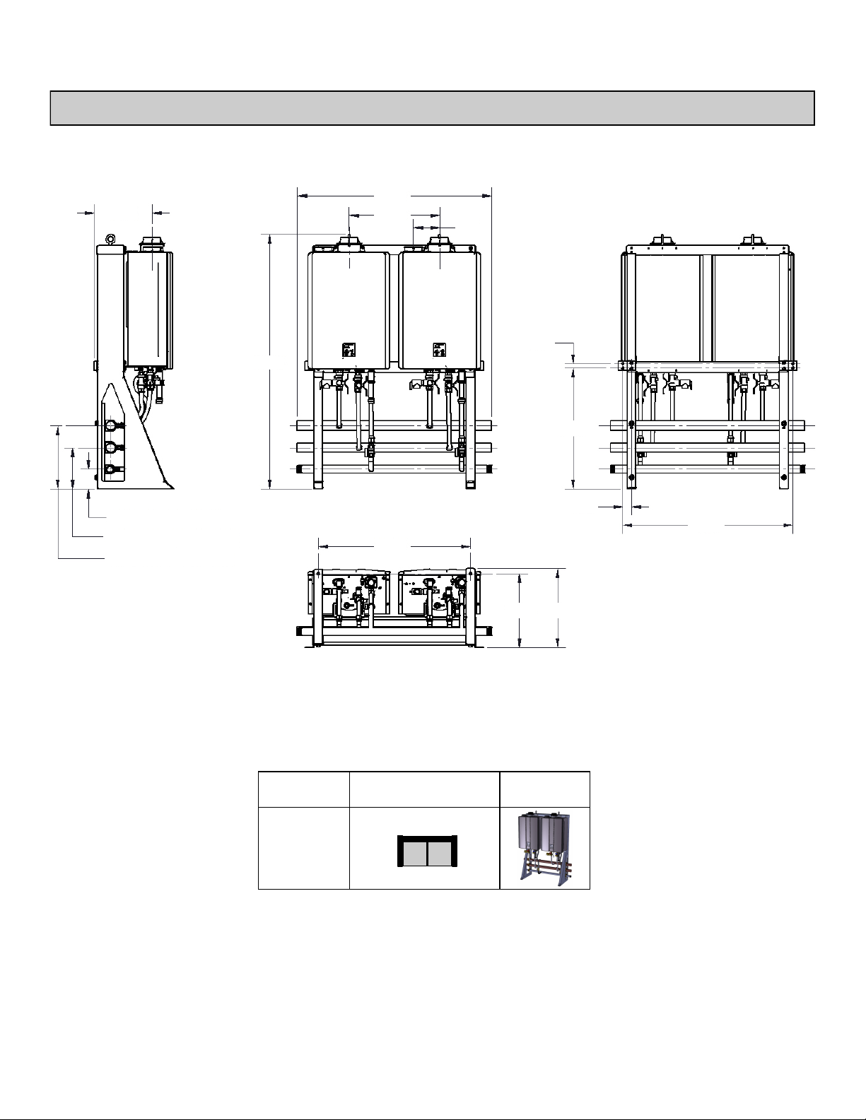
Specicaons
2 UNIT WALL MOUNT FRAME
LEFT
13.14
4.50 GAS (1-1/4”NPT)
9.38 COLD (2”COPPER)
14.38 HOT (2”COPPER)
57.69
FRONT
44.00
20.50
34.53
5.92
TYP
BACK
1.00
27.44
2.00
38.53
TRW02
BOTTOM
Configuration Illustration Model
16.78 18.00
11 Rinnai Rack Installation
Page 12
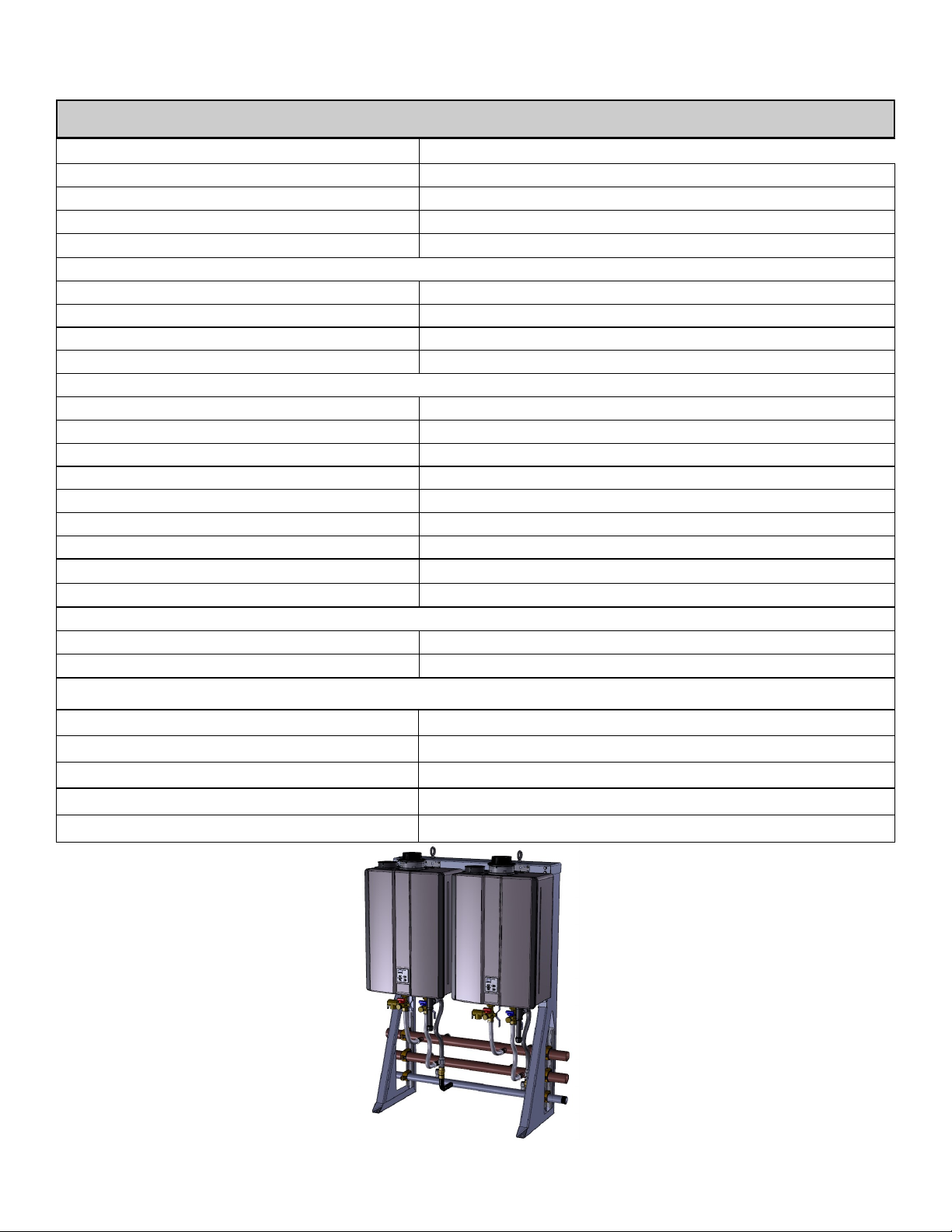
Specicaons
2 UNIT WALL MOUNT FRAME
Model
Water Heater Model
Crate Dimensions (HxLxD) - in 62 x 55 x 36
Weight - Fully Assembled - lbs 204
Weight - Shipping (total) - lbs 400
Rack Frame - Specifications
Frame Rail Type
Frame Material Aluminum (0.090 5052-H32)
Frame Finish
Color
Water & Gas Connections
Hot Water Trunk Line Diameter 2"
Cold Water Trunk Line Diameter 2"
Hot Water Trunk Line Material Rigid Copper
Cold Water Trunk Line Material Rigid Copper
Water Trunk Connection Type 2" PIPE
Gas Trunk Line Diameter 1-1/4"
Gas Trunk Connection Type 1-1/4” MNPT
Gas Trunk Line Material Sch 40 Steel
Gas Branch Line Material PVC Over CSST
Electric Requirements
Voltage AC 120 Volts—60 Hz
Maximum Current (Amperes) 8
RU98i, RUC98i, C199i, RU98e, C199e (NG/LP)
TRS02ILW
Sheet Metal
Powder Coat
Gray
BTU and Flow Rates for RU98i, RUC98i, C199i, RU98e, C199e (NG/LP)
Number of Tankless Water Heaters
Flow rate @ 70°F rise (gpm) 10.8
Flow rate @ 100°F rise (gpm) 7.6
Minimum input rate (Btuh) 15,200
Maximum input rate (Btuh) 398,000
2
TRS02ILW
12 Rinnai Rack Installation
Page 13
Specicaons
3 UNIT WALL MOUNT FRAME
LEFT
13.17
4.50 GAS (1-1/4”NPT)
9.38 COLD (2”COPPER)
14.38 HOT (2”COPPER)
57.69
FRONT
62.00
41.00
53.13
5.92
TYP
1.00
27.44
16.79 18.01
2.00
BACK
57.13
BOTTOM
Model Configuration Illustration
TRS03ILW
TRS23ILW
13 Rinnai Rack Installation
Page 14

Specicaons
3 UNIT WALL MOUNT FRAME
Model TRS03ILW TRS23ILW
Water Heater Model RU98i, RUC98i, C199i, RU98e, C199e (NG/LP)
Crate Dimensions (HxLxD) - in 62 x 75 x 36
Weight - Fully Assembled - lbs 291 218
Weight - Shipping (total) - lbs 487 414
Rack Frame - Specifications
Frame Rail Type
Frame Material
Frame Finish
Color
Water & Gas Connections
Hot Water Trunk Line Diameter 2"
Cold Water Trunk Line Diameter 2"
Hot Water Trunk Line Material Rigid Copper
Cold Water Trunk Line Material Rigid Copper
Water Trunk Connection Type 2" PIPE
Gas Trunk Line Diameter 1-1/4"
Gas Trunk Connection Type 1-1/4” MNPT
Gas Trunk Line Material Sch 40 Steel
Gas Branch Line Material PVC Over CSST
Electric Requirements
Voltage AC 120 Volts—60 Hz
Maximum Current (Amperes) 12
BTU and Flow Rates for RU98i, RUC98i, C199i, RU98e, C199e (NG/LP)
Aluminum (0.090 5052-H32)
Sheet Metal
Powder Coat
Gray
Number of Tankless Water Heaters 3 2
Flow rate @ 70°F rise (gpm) 16.2 10.8
Flow rate @ 100°F rise (gpm) 11.4 7.6
Minimum input rate (Btuh) 15,200 15,200
Maximum input rate (Btuh) 597,000 398,000
TRS03ILW
14 Rinnai Rack Installation
TRS23ILW
Page 15

Specicaons
4 UNIT FREE STANDING FRAME
57.69
FRONT
44.00
20.50
34.53
5.92
TYP
56.82
RIGHT
18.81
4.50 GAS (1-1/4”NPT)
9.38 COLD (2”COPPER)
14.38 HOT (2”COPPER)
BOTTOM
TRS04
TRS03
TRS02IL
TRS02
Configuration Illustration Model
Inline
(facing
same
direction)
Back
to
Back
26.29 28.59
15 Rinnai Rack Installation
Page 16

Specicaons
4 UNIT FREE STANDING FRAME
Model TRS04 TRS03 TRS02 TRS02IL
Water Heater Model RU98i, RUC98i, C199i, RU98e, C199e (NG/LP)
Crate Dimensions (HxLxD) - in 62 x 55 x 36
Weight - Fully Assembled - lbs 357 284 210 208
Weight - Shipping (total) - lbs 553 480 406 404
Rack Frame - Specifications
Frame Rail Type
Frame Material
Frame Finish
Color
Water & Gas Connections
Hot Water Trunk Line Diameter 2"
Cold Water Trunk Line Diameter 2"
Hot Water Trunk Line Material Rigid Copper
Cold Water Trunk Line Material Rigid Copper
Water Trunk Connection Type 2" PIPE
Gas Trunk Line Diameter 1-1/4"
Gas Trunk Connection Type 1-1/4” MNPT
Gas Trunk Line Material Sch 40 Steel
Gas Branch Line Material PVC Over CSST
Electric Requirements
Voltage AC 120 Volts—60 Hz
Maximum Current (Amperes) 16 12 8 8
BTU and Flow Rates for RU98i, RUC98i, C199i, RU98e, C199e (NG/LP)
Aluminum (0.090 5052-H32)
Sheet Metal
Powder Coat
Gray
Number of Tankless Water Heaters
Flow rate @ 70°F rise (gpm) 21.6 16.2 10.8
Flow rate @ 100°F rise (gpm) 15.2 11.4 7.6
Minimum input rate (Btuh) 15,200
Maximum input rate (Btuh) 796,000 597,000 398,000
TRS04
16 Rinnai Rack Installation
TRS03 TRS02
4 3 2
TRS02IL
Page 17

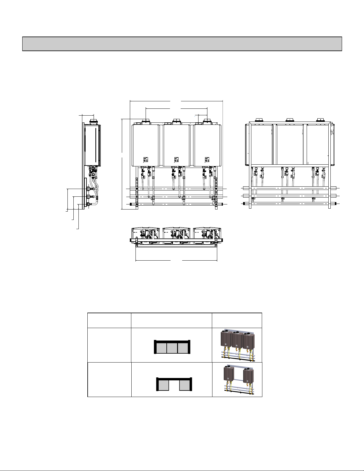
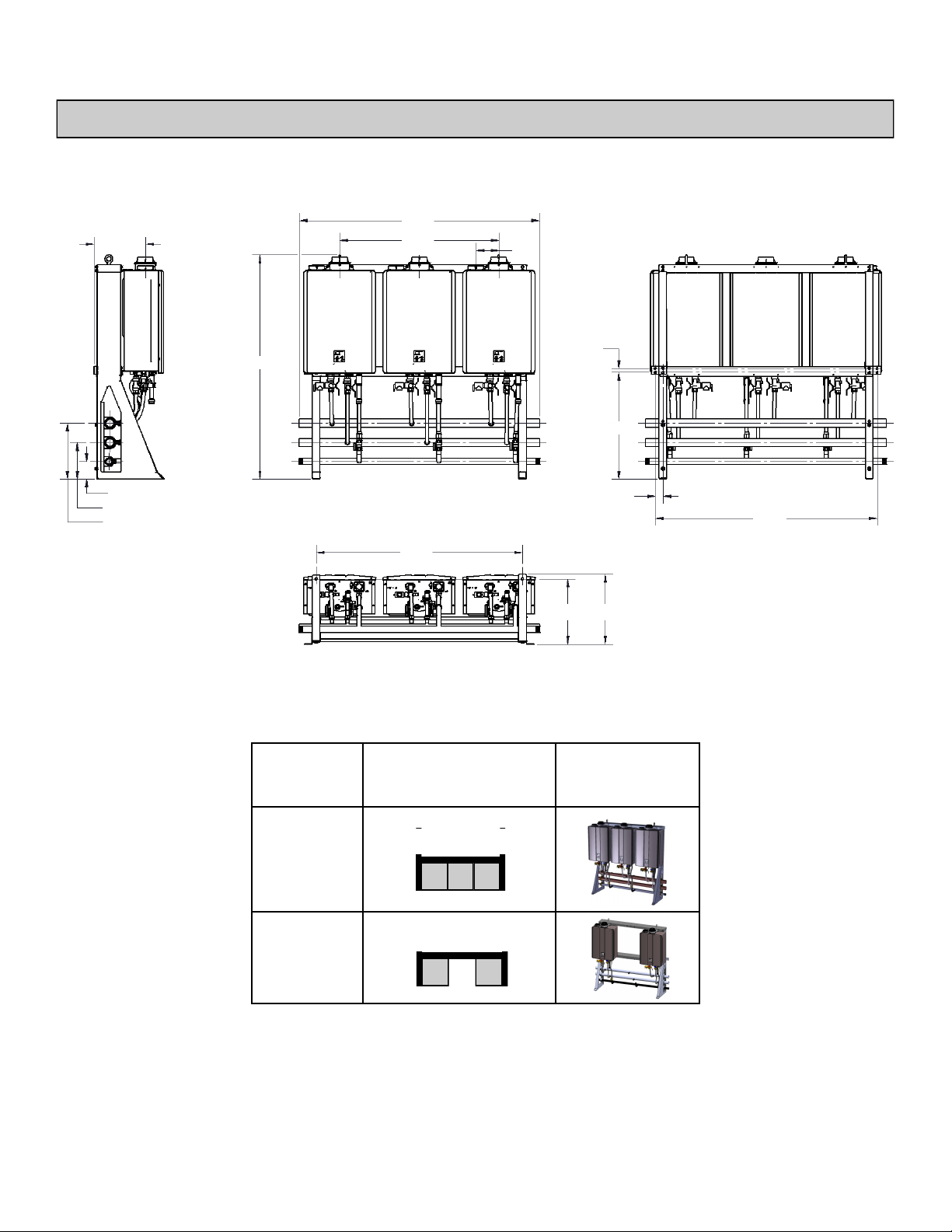
Specicaons
6 UNIT FREE STANDING FRAME
57.69
FRONT
62.00
41.01
53.13
5.92
TYP
RIGHT
18.81
9.38 COLD (2”COPPER)
14.38 HOT (2”COPPER)
4.50 GAS (1-1/4”NPT)
26.29 28.59
BOTTOM
Configuration Model Illustration
TRS06
TRS05
TRS03IL
17 Rinnai Rack Installation
TRS06
TRS46
TRS23IL
Configuration Model Illustration
Page 18
Specicaons
6 UNIT FREE STANDING FRAME
Model TRS06 TRS05 TRS46 TRS36 TRS03IL TRS23IL
Water Heater Model RU98i, RUC98i, C199i, RU98e, C199e (NG/LP)
Crate Dimensions (HxLxD) - in 62 x 75 x 36
Weight - Fully Assembled - lbs 526 452 378 284 284 210
Weight - Shipping (total) - lbs 722 649 576 480 480 406
Rack Frame - Specifications
Frame Rail Type
Frame Material
Frame Finish
Color
Water & Gas Connections
Hot Water Trunk Line Diameter
Cold Water Trunk Line Diameter
Hot Water Trunk Line Material
Cold Water Trunk Line Material
Water Trunk Connection Type
Gas Trunk Line Diameter
Gas Trunk Connection Type
Gas Trunk Line Material Sch 40 Steel
Gas Branch Line Material PVC Over CSST
Electric Requirements
Voltage AC 120 Volts—60 Hz
Max Current (Amperes) 24 20 16 12 12 8
Aluminum (0.090 5052-H32)
2-1/2" 2”
2-1/2" 2”
2-1/2” PIPE 2” PIPE
1-1/2" 1-1/4”
1-1/2” MNPT 1-1/4”MNPT
Sheet Metal
Powder Coat
Gray
Rigid Copper
Rigid Copper
BTU and Flow Rates for RU98i, RUC98i, C199i, RU98e, C199e (NG/LP)
Number of Tankless Water Heaters
Flow rate @ 70°F rise (gpm) 32.4 27.0 16.2 21.6 10.8
Flow rate @ 100°F rise (gpm) 22.8 19.0 11.4 15.1 7.6
Minimum input rate (Btuh) 15,200
Maximum input rate (Btuh) 1,194,000 995,000 597,000 796,000 398,000
TRS06
18 Rinnai Rack Installation
TRS05
TRS03IL
6 5 3 4 2
TRS36
TRS46
TRS23IL
Page 19

Clearances
Install the rack system so that the clearances shown below (specified for the water heater in the RUC98i and
RU98e installation manual) are followed.
Top
of Heater
Front
of Heater
of Heater
Ground/Bottom
Indoor models: RU98i, RUC98i, C199i
to
Combustibles
inches (mm)
to Non-
Combustibles
inches (mm)
Side
Front
of Heater
Outdoor models: RU98e, C199e
Ground/Bottom
to
Combustibles
inches (mm)
Top
of Heater
Side
of Heater
to Non-
Combustibles
inches (mm)
Top of Heater
Back of Heater
Front of Heater
Sides of Heater
Ground/Bottom
Vent
* 0 inches from vent components and condensate
drain line.
The clearance for servicing is 24 inches in front of the
water heater.
For closet installation, clearance is 6 inches (152 mm
from the front.
19 Rinnai Rack Installation
6 * (152) 2 *(51)
0 (zero) 0 (zero)
6 (152) 6 (152)
2 (51) 1/2 (13)
12 (305) 12 (305)
0 (zero) 0 (zero)
Top of Heater
Back of Heater
Front (panel)
Front (exhaust)
Sides of Heater
Ground/Bottom
The clearance for servicing is 24 inches in front of the
water heater.
12 (305) 2 (51)
0 (zero) 0 (zero)
24 (610) 0 (zero)
24 (610) 24 (610)
6 (152) 1/8 (3.2)
12 (305) 2 (51)
Page 20

Hoisng (Liing Lugs)
Lugs are installed on the top side of the following
racks for hoisting and moving. The lines or cables to
the lugs should be at a 90° angle. Use a spreader
lifting bar to hoist these racks.
Weights of the complete assemblies are available in
the Specifications section of this manual.
NOTE: DO NOT hoist the crate or palette.
Spreader Lifting Bar
MODELS AVAILABLE WITH LIFTING LUGS
TRS02ILW TRS02 TRS02IL TRS03
TRS03ILW TRS03IL TRS04 TRS05
TRS06
TRS023ILW
TRS046
TRS036 TRS023IL
90°
Hoisng (Straps)
For the TRW02 and TRW03 wall mounted racks, use hoisting straps looped around the top frame.
Weights of the complete assemblies are available in the Specifications section of this manual.
NOTE: DO NOT hoist the crate or palette.
TRW02
TRW023
20 Rinnai Rack Installation
TRW03
Hoisting Straps
Page 21
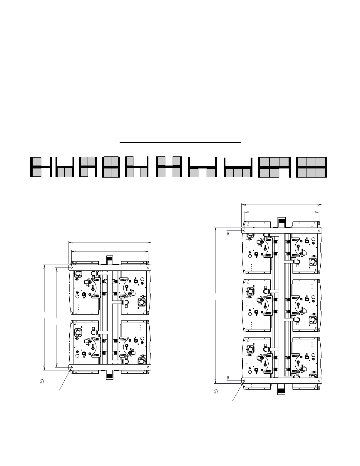
28.50
26.50
53.09
0.563
(4) Plcs
55.11
26.50
28.50
36.53
34.51
0.563
(4) Plcs
Securing Free Standing Racks
1. Use 4-1/2” HILTI KB-TZ expansion anchors or approved equivalent. Minimum embedment (hef) = 3.25”.
Minimum concrete thickness to be 6”.
2. All mechanical components shall be anchored and installed per the notes in this manual. Where no detail is
indicated, anchorage of equipment to building structure shall be in accordance to the applicable naonal
and/or local codes having jurisdicon.
3. The size and embedment specied are for anchors installed in stone or aggregate concrete only, for other
anchorage details the contractor or engineer on record for the building shall consult with a licensed structural engineer for all anchorage of equipment not called out in this manual.
4. In the event of a conict or inconsistency between items indicated in this manual with code requirements,
the more stringent standard shall prevail.
FREE STANDING MODELS AVAILABLE
TRS02 TRS02IL TRS03 TRS04 TRS36 TRS46 TRS23IL TRS03IL TRS05 TRS06
Boom view of
free standing
21 Rinnai Rack Installation
racks.
(Flex line illustraons
have been removed
for clarity)
Page 22

Securing Wall Mount Racks (ILW)
WARNING
ANALYSIS OF THE WALL AND APPROPRIATE HANGING METHODS BEFORE ATTEMPTING TO HANG THE
TRS SYSTEM. FAILURE TO COMPLY WITH THE ABOVE REQUIREMENT COULD RESULT IN SUBSTANTIAL
PROPERTY DAMAGE, SEVERE PERSONAL INJURY OR DEATH.
THE WALL MUST BE CABABLE OF CARRYING THE OPERATING WEIGHT OF THE
INSTALLED TRS SYSTEM. CONSULT A STRUCTURAL ENGINEER FOR STRUCTURAL
• Idenfy the installaon locaon and conrm that the installaon will meet all required clearances.
• The size and embedment specied are for anchors installed in stone or aggregate concrete only, for other
anchorage details the contractor or engineer on record for the building shall consult with a licensed structural
engineer for all anchorage of equipment not called out in this manual.
• In the event of a conict or inconsistency between items indicated in this manual with code requirements, the
more stringent standard shall prevail.
WALL RACK MODELS AVAILABLE
TRS02ILW, TRS03ILW, & TRS23ILW
1. Using the holes in the wall bracket, Securely aach the rack to the wall. Ensure that the aachment strength is
sucient.
2. For oor anchors, use 4-1/2” HILTI KB-TZ expansion anchors or approved equivalent. Minimum embedment
(hef) = 3.25”. Minimum concrete thickness to be 6”.
TRS02ILW
TRS03ILW
TRS23ILW
(Brackets are located
on both sides of rack)
22 Rinnai Rack Installation
Page 23

Securing Wall Hanging Racks (TRW)
WARNING
ANALYSIS OF THE WALL AND APPROPRIATE HANGING METHODS BEFORE ATTEMPTING TO HANG THE
TRS SYSTEM. FAILURE TO COMPLY WITH THE ABOVE REQUIREMENT COULD RESULT IN SUBSTANTIAL
PROPERTY DAMAGE, SEVERE PERSONAL INJURY OR DEATH.
THE WALL MUST BE CABABLE OF CARRYING THE OPERATING WEIGHT OF THE
INSTALLED TRS SYSTEM. CONSULT A STRUCTURAL ENGINEER FOR STRUCTURAL
• Idenfy the installaon locaon and conrm that the installaon will meet all required clearances.
• The size and embedment specied are for anchors installed in stone or aggregate concrete only, for other
anchorage details the contractor or engineer on record for the building shall consult with a licensed structural
engineer for all anchorage of equipment not called out in this manual.
• In the event of a conict or inconsistency between items indicated in this manual with code requirements, the
more stringent standard shall prevail.
WALL HANGING RACK MODELS AVAILABLE
TRW02, TRW03, & TRW23
1. Using the holes in the wall hanging bracket, Securely
aach the bracket level to the wall. Ensure that the
aachment strength is sucient.
2. Li the wall hanging rack , and insert the top of the
frame into the bracket.
3. Secure the front of the bracket to the front of the wall
hanging frame with a #12 X 3/4 drill point screw.
23 Rinnai Rack Installation
Page 24

Relief Valve Piping
Each Rinnai tankless water heater on the TRS comes installed with Isolaon valves and a pressure relief valve.
Refer to the installaon and operaon manual for more informaon on proper piping for the relief valve drain.
Pressure Relief
Valve
Isolation Valve
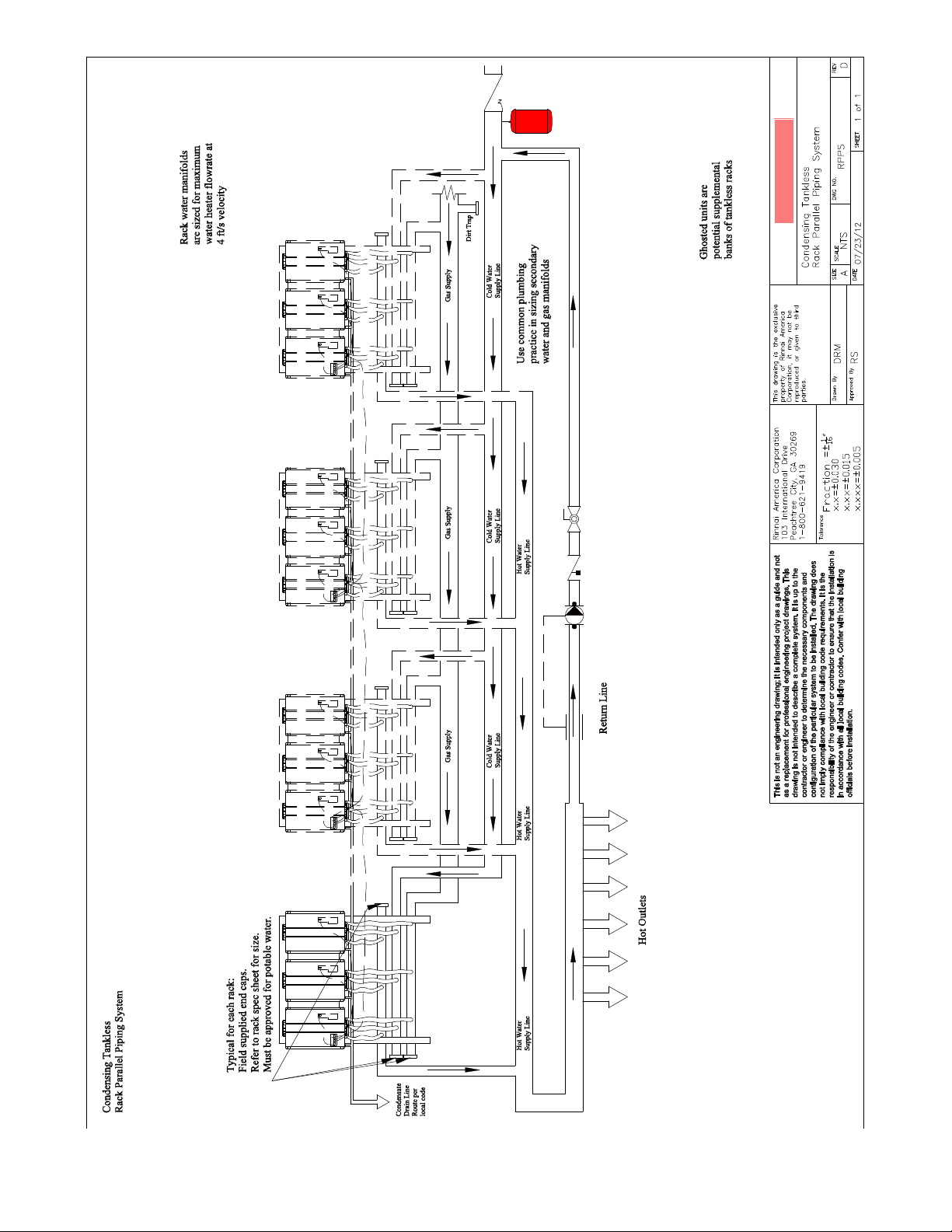
Piping for Mulple Racks
Mulple rack systems should be installed in parallel using a secondary manifold from the building cold and hot
water supply. Reference the drawing on the following page for guidance on plumbing mulple racks in a parallel
piping system.
A low pressure gas regulator must be installed prior to the rack system. Note the maximum cumulave input for
the system when sizing the gas regulator.
Use common plumbing pracce and reference all applicable codes when sizing the secondary manifolds and gas
regulator.
24 Rinnai Rack Installation
Page 25
25 Rinnai Rack Installation
Page 26

End Caps / Connecons
End caps are to be eld supplied and to be of the following materials:
• Cold water cap - Brass or Copper
• Hot water cap - Brass or Copper
• Gas cap - black iron
Once ow direcon and gas supply side is determined the other (opposite) side of the manifold must be capped.
See the example below.
Leak check the capped ends of the manifolds.
COLD IN
CAP
CAP
HOT OUT
CAP
GAS IN
26 Rinnai Rack Installation
Page 27

Condensate Drain
Checklist for Plumbing
Each Rinnai tankless water heater has a condensate
drain outlet on the boom of the unit. A drain line
must be connected to each water heater.
Condensate Drain Manifold must be eld fabricated
(not shown in diagram)
Condensate piping shall be CPVC or PVC material and
shall not be smaller than the drain connecon on the
appliance.
Components of the condensate drainage shall be
CPVC or PVC material. All components shall be
selected for the pressure and temperature rang of
the installaon.
Where the drain pipes from more than one unit are
manifolded together for condensate drainage, the
pipe or tubing shall be sized in accordance with an
approved method as dictated by local codes.
Condensate must be disposed of according to local
codes.
□ Purge the water line of all debris and air by
closing the hot isolaon valve and opening the
cold isolaon valve and its drain. Debris will
damage the water heater. Use a bucket or hose
if necessary.
□ Ensure that hot and cold water lines are not
crossed to the unit and are leak free.
□ Ensure that a pressure relief valve is installed with
a rang that exceeds the BTU input of the water
heater model. Refer to the rang plate on the
side of the water heater for BTU input.
□ Clean the inlet water lter by closing the cold and
hot water inlet isolaon (shut-o) valves. Put a
bucket under the lter at the boom of the water
heater to catch any water that is contained inside
the unit. Unscrew the water lter. Rinse the
lter to remove any debris. Install the lter and
open the isolaon valves.
Piping Diagram for Basic Installaon
Water
drain plug
Hot water
outlet
The condensate drain pipe (along its entire
length) must be at least the same diameter
as the drain line.
Gas
connection
Condensate
trap drain plug
Cold water
inlet
Condensate
drain line
□ Check for proper water pressure to the water
heater. Minimum water pressure is 50 psi. Rinnai
recommends 60-80 psi for maximum
performance.
□ Ensure any issues regarding water quality have
been properly addressed.
27 Rinnai Rack Installation
Page 28
Installaon of Gas Supply
Connect Electricity
WARNING
1. A licensed professional must install the gas
supply.
2. Turn o 120v power supply.
3. Turn o the gas.
4. Gas is ammable. Do not smoke or provide other
ignion sources while working with gas.
5. Do not turn on the water heater or gas unl all
fumes are gone.
MUST DO
Check the type of gas and the gas inlet pressure
before connecng the water heater. If the water
heater is not of the gas type that the building is
supplied with, DO NOT connect the water heater.
Contact the dealer for the proper unit to match
the gas type.
Check the gas supply pressure immediately
upstream at a locaon provided by the gas
company. Supplied gas pressure must be within
the limits shown in the Specicaons secon of
this manual with all gas appliances operang.
Before placing the appliance in operaon, all joints
including the heater must be checked for gas
ghtness by means of leak detector soluon, soap
and water, or an equivalent nonammable
soluon, as applicable. (Since some leak test
soluons, including soap and water, may cause
corrosion or stress cracking, the piping shall be
rinsed with water aer tesng, unless it has been
determined that the leak test soluon is noncorrosive.)
Use approved connectors to connect the unit to
the gas line. Purge the gas line of any debris
before connecon to the water heater.
Any compound used on the threaded joint of the
gas piping shall be a type that resists the acon of
liqueed petroleum gas (propane / LPG).
The gas supply line shall be gas ght, sized, and so
installed as to provide a supply of gas sucient to
meet the maximum demand of the heater and all
other gas consuming appliances at the locaon
without loss of pressure.
INFORMATION
If in doubt about the size of the gas line, refer to
an approved pipe sizing chart
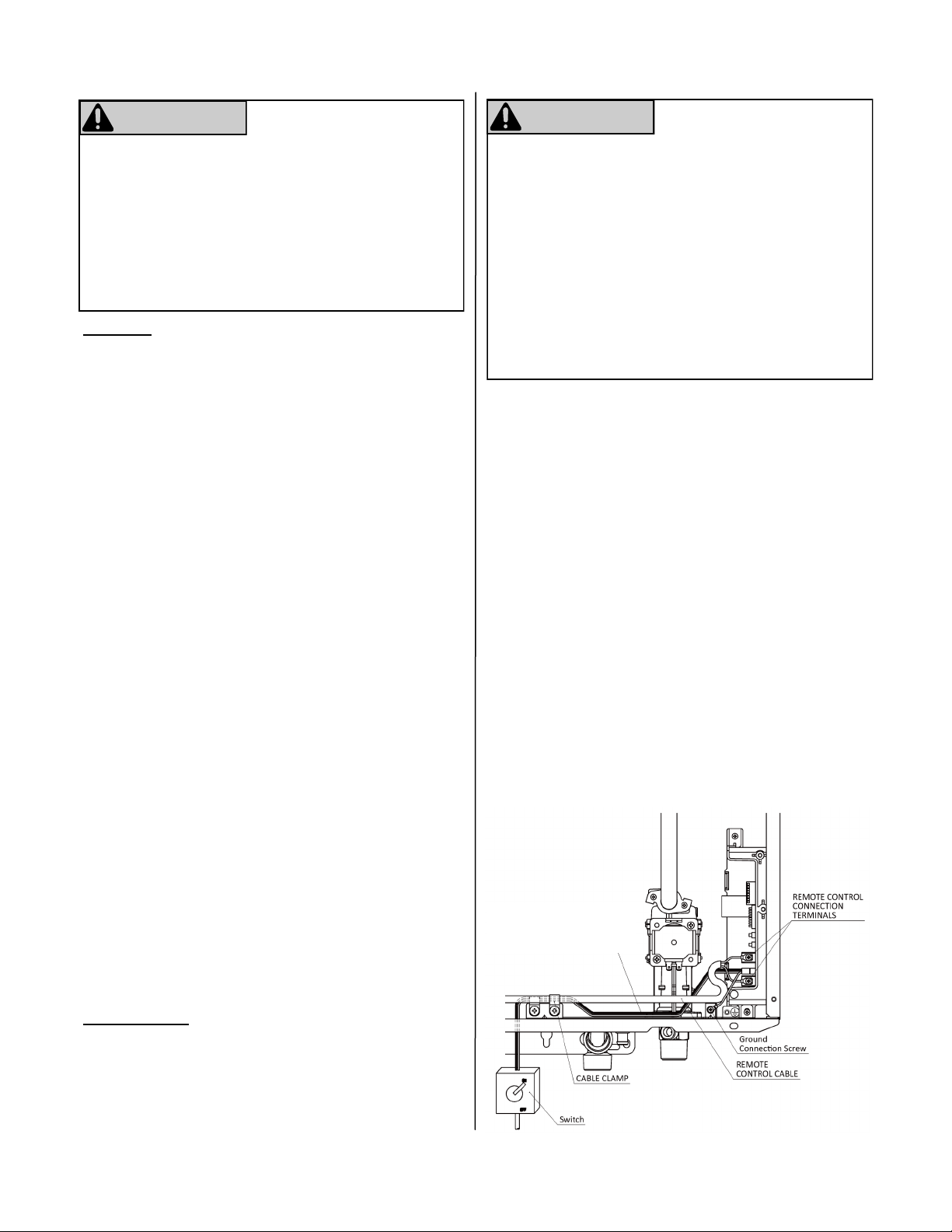
WARNING
Do not use an extension cord or an adapter plug with
this appliance.
The water heater must be electrically grounded in
accordance with local codes and ordinances or, in the
absence of local codes, in accordance with the
Naonal Electrical Code, ANSI/NFPA No. 70.
Indoor water heaters are equipped with a threeprong (grounding) plug for your protecon against
shock hazard and should be plugged directly into a
properly grounded three-prong receptacle. Do not
cut or remove the grounding terminal from this plug.
Do not rely on the gas or water piping to ground the
water heater. A screw is provided in the juncon box
for the grounding connecon.
The water heater requires 120 VAC, 60 Hz power from
a properly grounded circuit.
If using the 5 foot long power cord, plug it into a
standard 3 prong 120 VAC, 60 Hz properly grounded
wall outlet.
On outdoor models, a disconnect switch must be
provided and installed for the incoming 120 VAC
power. It should be a type that is suitable for outdoor
use. Check the Naonal Electrical Code, ANSI/NFPA
70 and your local codes for a proper switch type to
use in your area.
The wiring diagram is located on the Technical Sheet
aached to the inside of the front cover.
120V Wiring
Blue or Black wire: hot leg
Brown or White Wire: neutral
28 Rinnai Rack Installation
Page 29

MSB Installaon
All of the water heaters should be electronically connected using the MSB control system. The only excepon is when a water heater is dedicated to recovering a
tank. The MSB kits can electronically connect up to 25
water heaters.
When over 5 water heaters are connected together,
MSB-M units are connected using MSB-C2 kits.
If mulple MSB-M are used, then at least three water
heaters should be connected to each MSB-M. Example:
With 7 water heaters, one MSB-M should control 4 water heaters and the other MSB-M should control 3 water heaters.
The temperature seng for all of the connected water
heaters is controlled by the temperature controller
connected to the water heater with the master MSB
Board. Temperature controllers connected to the other
units will provide maintenance codes for their respecve units.
On applicable models a single MCC-91 can be connected to the master MSB Board to provide temperatures
greater than 140ºF for all the water heaters in the MSB
system.
In the diagram above, 25 water heaters are
electronically connected. Each bank of 5 is controlled
by an MSB-M control board. These boards are
connected to each other with MSB-C2 cables. One
MSB-M is the controlling or master MSB-M for the
enre system.
M MSB-M control board
A Connector cable A (part of MSB-M kit; replace
with MSB-C3 cables for V Series)
C1 MSB-C1 cable (9.8 feet) for connecting water
heaters within a banked system (up to 5), (use
MSB-C3 cables for V Series)
C2 MSB-C2 cable (26.2 feet) for connecting MSB-M
control boards (up to 5)
29 Rinnai Rack Installation
Page 30

MSB Installaon
1. On the master MSB, one connector is connected to
the terminal connector and the other one is connected to the MSB Communicaon cable.
2. When 2 MSB boards are used a MSB Communica-
on cable will be installed between the master
MSB board and the second MSB. The open connector will have the Terminal connector installed
on both MSB boards.
A maximum of 5 MSB boards can be connected to each
other. The terminal connector is connected on the terminal MSB which has an open connector.
NOTE: When viewing the installed MSB board, the dip
switch will be as shown below (upside down).
Master MSB board
2nd MSB board
2nd to 4th
MSB board
3. Set No 3 switch on the master MSB to ON. The LED light 6
should turn ON conrming the connecon.
4. Set No 4 switch on the second MSB to ON. The LED light 6
should turn ON conrming the connecon.
5. Set No 3 and No 4 switches on the third MSB board to ON. The
LED light 6 should turn ON conrming the connecon.
6. Set the No 5 switch on the fourth MSB board to ON. The LED
light 6 should turn ON conrming the connecon.
5th or Terminal
MSB board
7. Set No 3 and No 5 switches on the on the h MSB board to
ON. The LED light 6 should turn ON conrming the connecon.
30 Rinnai Rack Installation
Page 31

Final Checklist
□ The water heater is not subject to corrosive
compounds in the air.
□ The water supply does not contain chemicals or
exceed total hardness that will damage the heat
exchanger.
□ Clearances from the water heater unit are met.
□ Clearances from the vent termination / air intake
are met.
□ For indoor models, ensure you have used the
correct venting products for the model installed
and that you have completely followed the venting
manufacturer’s installation instructions and these
installation instructions.
□ For indoor models, verify that the vent system
does not exceed the maximum length for the
number of elbows used.
□ For indoor models, verify that SW 1 in DIPSW 1
has been adjusted for vent length if necessary.
Refer to the section on Maximum Vent Length.
□ Purge the water line of all debris and air by closing
the hot isolation valve and opening the cold
isolation valve and its drain. Debris will damage
the water heater. Use a bucket or hose if
necessary.
□ Ensure that hot and cold water lines are not
crossed to the unit and are leak free.
□ A manual gas control valve has been placed in the
gas line to the water heater.
□ Ensure that a pressure relief valve is installed with
a rating that exceeds the BTU input of the water
heater model. Refer to the rating plate on the side
of the water heater for BTU input.
□ Clean the inlet water filter by closing the cold and
hot water inlet isolation (shut-off) valves. Put a
bucket under the filter at the bottom of the water
heater to catch any water that is contained inside
the unit. Unscrew the water filter. Rinse the filter
to remove any debris. Install the filter and open
the isolation valves.
□ Check the gas lines and connections for leaks.
□ Confirm that the electricity is supplied from a 120
VAC, 60 Hz power source, is in a properly
grounded circuit, and turned on.
□ Verify the temperature controller is functioning
properly.
□ Verify that SW 2 and SW 3 in DIPSW 1 is set
correctly for your altitude.
□ Verify the system is functioning correctly by
connecting your manometer to the gas pressure
test port on the water heater. Operate all gas
appliances in the home or facility at high fire. The
inlet gas pressure at the water heater must not
drop below that listed on the rating plate.
□ DO NOT introduce toxic chemicals such as those
used for boiler water treatment to the potable
water used for space heating.
□ If the water heater is not needed for immediate
use, then drain the water from the heat exchanger.
□ Install the front panel.
□ Explain to the customer the importance of not
blocking the vent termination or air intake.
□ Explain to the customer the operation of the water
heater, safety guidelines, maintenance, and
warranty.
□ The installation must conform with local codes or,
in the absence of local codes, with the National
Fuel Gas Code, ANSI Z223.1/NFPA 54, or the
Natural Gas and Propane Installation Code, CSA
B149.1. If installed in a manufactured home, the
installation must conform with the Manufactured
Home Construction and Safety Standard, Title 24
CFR, Part 3280 and/or CAN/SCA Z240 MH
Series, Mobile Homes.
□ Inform the consumer if the isolation valves are not
installed or if a water softening system is not
installed.
□ Leave the entire manual taped to the water
heater (indoor models), temperature controller
(outdoor models), or give the entire manual
directly to the consumer.
□ Confirm that the gas inlet pressure is within limits.
□ Confirm that the water heater is rated for the gas
type supplied.
31 Rinnai Rack Installation
Page 32
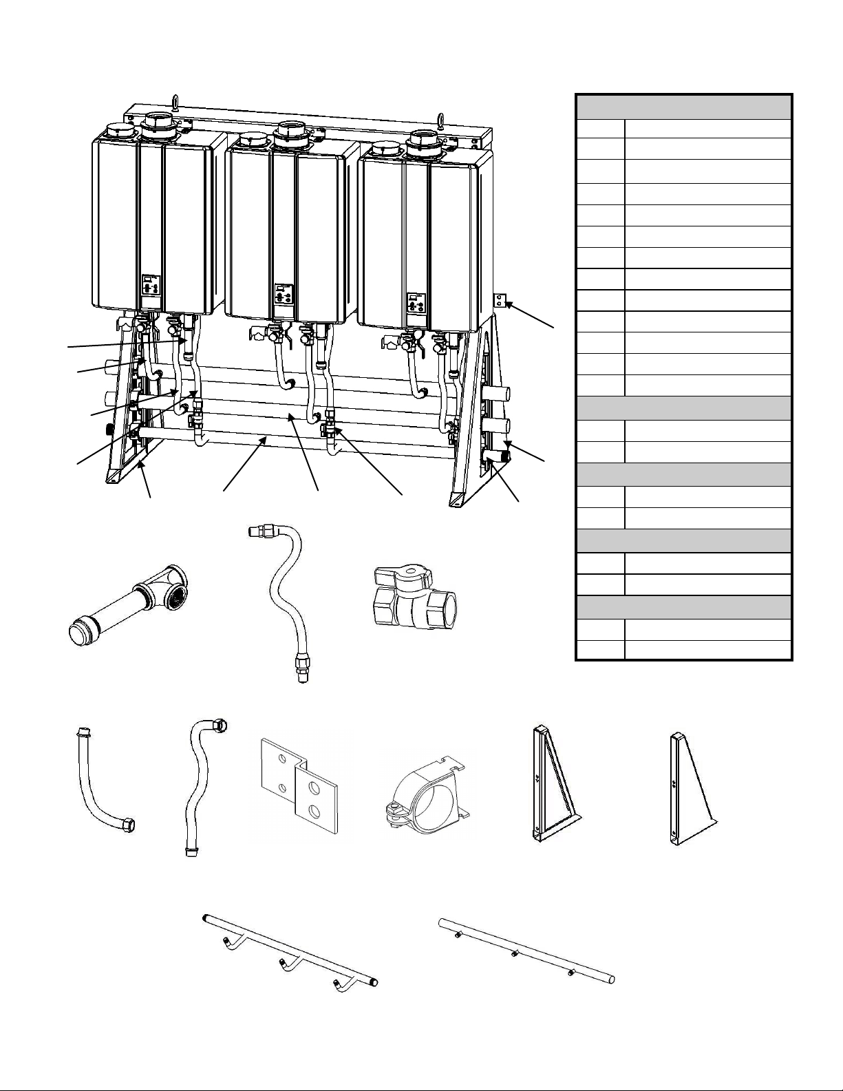
TRS REPLACEMENT PARTS REFERENCE NUMBERS
1
4
5
2
1
11
13/15/17/19
2
14/16/18/20
3
3
7/8/9/10
12
ALL TRS/TRW
REF. #
1 Dirt Leg
2 Gas Flex Line Assembly
3 Gas Valve
4 Hot Water Flex Line
5 Cold Water Flex Line
6 Wall Bracket
7 Cush Clamp 2.63ID
8 Cush Clamp 2.125ID
9 Cush Clamp 1.90ID
6
10 Cush Clamp 1.66ID
11 Frame, Rack Left Rear
12 Frame, Rack Right Rear
13 Manifold, Gas - 6B2B
14 Manifold, Water - 6B2B
TRS02/TRS03/TRS04
15 Manifold, Gas - 4B2B
16 Manifold, Water - 4B2B
17 Manifold, Gas - 3WM
18 Manifold, Water - 3WM
19 Manifold, Gas - 2WM
20 Manifold, Water - 2WM
Description
TRS05/TRS06
TRW03/TRS03IL
TRW02/TRS02IL
5
4
13/15/17/19
32 Rinnai Rack Installation
6
7/8/9/10
11
14/16/18/20
12
Page 33

TRW REPLACEMENT PARTS REFERENCE NUMBERS
1
4
5
2
ALL TRW
REF. #
1 Dirt Leg
2 Gas Flex Line Assembly
3 Gas Valve
4 Hot Water Flex Line
5 Cold Water Flex Line
6 Cush Clamp 2.63ID
7 Cush Clamp 2.125ID
8 Cush Clamp 1.90ID
9 Cush Clamp 1.66ID
10 Manifold, Gas - 3WM
11 Manifold, Water - 3WM
12 Manifold, Gas - 2WM
13 Manifold, Water - 2WM
Description
TRW03
TRW02
5
1
10/12
2
6/7/8/9
11/13
6/7/8/9
3
3
10/12 11/13
33 Rinnai Rack Installation
Page 34

Extended Limited LABOR Warranty* Tankless Rack System
Rinnai is providing the opportunity to extend your Rinnai Standard Limited Warranty for labor only on the tankless water
heater product installed as part of the Tankless Rack System and used in a commercial applicaon. You must register the
product within 30 days of purchase of the system to qualify.
The limited warranty period on the Labor coverage for Tankless Water Heaters installed on the Tankless Rack System is extended for an addional 12 months (a total of 24 months labor coverage from date of purchase), when registered. Products
not registered will sll be covered under the Rinnai standard product limited warranty as provided in the Operang Instrucon manual which comes with the Tankless water heater. Warranty informaon is also available on Rinnai's web
site at www.rinnai.us. You can register at www.rinnairegistraon.com or by calling 1-866-RINNAI-1 (746-6241), except
registraon is not required in California and Quebec.
What is covered?
This Limited Warranty covers any defects in materials or workmanship when the product is installed and operated according
to Rinnai wrien installaon instrucons, subject to the terms within this Limited Warranty document. This Limited
Warranty applies only to products that are installed correctly. Improper installaon may void this Limited Warranty. In
order for this warranty to apply, it is required that you use a licensed professional who has aended a Rinnai installaon
training class before installing this water heater. This Limited Warranty extends to the original purchaser and subsequent
owners, but only while the product remains at the site of the original installaon. This Limited Warranty only extends
through the rst installaon of the product and terminates if the product is moved or reinstalled at a new locaon.
How long does coverage last?
REGISTRATION REQUIRED*
Item
Labor Parts Heat Exchanger
Tankless Water Heaters 1 year (2) 5 years (1) 5 years (1)
Rack and Components 1 year
Period of Coverage (from date of purchase)
Only applicable if product is registered within 30 days of purchase and the other condions are met. Note to California
and Quebec Residents, and residents of other jurisdicons that prohibit warranty benets condioned on registraon,
registraon is not required to obtain longer warranty periods and failure to register does not diminish your warranty
rights. www.rinnai.us/warranty
[1] The warranty period is reduced to 3 years from date of purchase when the water heater is used as a circulang water heater within a hot water
circulaon loop, where the water heater is in series with a circulaon system and all circulang water ows through the water heater, and where an
on-demand recirculaon system is not incorporated.
On-demand recirculaon is dened as a hot water recirculang loop or system that ulizes exisng hot and cold lines or a dedicated return line, and
only acvates when hot water is used. It can be acvated by a push buon, moon sensor, or voice acvaon but not by a temperature sensor. A
mer added to a standard recirculang pump is not considered as on-demand.
[2] Labor coverage is extended to 5 years in residenal applicaons and to 2 years in commercial applicaons if the product is registered within 30 days
(except registraon is not required in California and Quebec) and/or if the other condions above in the Residenal Applicaons and Commercial
Applicaons secons are sased.
What will Rinnai do?
Rinnai will repair or replace the covered product or any part or component that is defecve in materials or workmanship as
set forth. Rinnai will pay reasonable labor charges associated with the repair or replacement of any part or component of
the tankless water heater. All repair parts must be genuine Rinnai parts. All repairs or replacements must be performed by
a licensed professional that is properly trained, state qualied or licensed to do the type of repair.
Replacement of the product may be authorized by Rinnai only. Rinnai does not authorize any person or company to assume
for it any obligaon or liability in connecon with the replacement of the product. If Rinnai determines that repair of a
product is not possible, Rinnai will replace the product with a comparable product at Rinnai’s discreon. The warranty claim
for product parts and labor may be denied if a component or product returned to Rinnai is found to be free of defects in
material or workmanship; damaged by improper installaon, use or operaon; or damaged during return shipping.
34 Rinnai Rack Installation
Page 35

How do I get service?
You must contact a licensed professional for the repair of a product under this Limited Warranty. For the name of a licensed professional please contact your place of purchase, visit the Rinnai website (www.rinnai.us), call Rinnai at 1-800-621
-9419 or write to Rinnai at 103 Internaonal Drive, Peachtree City, Georgia 30269.
Proof of purchase is required to obtain warranty service. You may show proof of purchase with a dated sales receipt, or by
registering within 30 days of purchasing the product. To register your tankless water heater, please visit www.rinnai.us.
For those without internet access, please call 1-866-RINNAI1 (746-6241). Receipt of Registraon by Rinnai will constute
proof-of-purchase for this product. However, Registraon is not necessary in order to validate this Limited Warranty.
What is not covered?
This Limited Warranty does not cover any failures or operang dicules due to the following:
• accident, abuse, or misuse
• alteraon of the product or any component part
• misapplicaon of this product
• improper installaon (such as but not limited to)
Product being installed in a corrosive environment
condensate damage
improper venng
incorrect gas type
incorrect gas or water pressure
absence of a drain pan under the appliance
• water quality
• improper maintenance (such as but not limited to scale build-up, freeze damage, or vent blockage)
• incorrect sizing
• any other cause not due to defects in materials or workmanship
• Problems or damage due to res, ooding, electrical surges, freezing or any acts of God.
• force majeure
There is no warranty coverage on product installed in a closed loop applicaon, commonly associated with space heang
only applicaons.
The integrated controller on indoor models has a 1 year warranty on parts.
This Limited Warranty does not apply to any product whose serial number or manufacture date has been defaced. This
Limited Warranty does not cover any product used in an applicaon that uses chemically treated water such as a pool or
spa heater. This appliance is suitable for lling large or whirlpool bath tubs with potable water.
Limitaon on warranes
No one is authorized to make any other warranes on behalf of Rinnai America Corporaon. Except as expressly provided
herein, there are no other warranes, expressed or implied, including, but not limited to warranes of merchantability or
tness for a parcular purpose, which extend beyond the descripon of the warranty herein and further Rinnai shall not be
liable for indirect, incidental, special, consequenal or other similar damages that may arise, including lost prots, dama ge
to person or property, loss of use, inconvenience, or liability arising from improper installaon, service or use. Some states
do not allow the exclusion or limitaon of incidental or consequenal damages, so the above limitaon may not apply to
you.
Any implied warranes of merchantability and tness arising under state law are limited in duraon to the period of coverage provided by this Limited Warranty, unless the period provided by state law is less. Some states do not allow limitaons
on how long an implied Limited Warranty lasts, so the above limitaon may not apply to you.
This Limited Warranty gives you specic legal rights, and you may also have other rights which vary from state to state.
www.rinnai.us/warranty
35 Rinnai Rack Installation
Page 36

Rinnai America Corporaon • 103 Internaonal Drive, Peachtree City, GA 30269
©2014 Rinnai America Corporaon. Rinnai is connually updang and improving products; therefore, specicaons are subject
to change without prior noce. Local, state, provincial, federal and naonal fuel gas codes must be adhered to prior to and upon installaon.
Toll-Free: 1-800-621-9419 • Phone: 678-829-1700 • www.rinnai.us
100000294(06)
6/2015
36 Rinnai Rack Installation
 Loading...