

Rinnai Symmetry RDV3611ETRN, Symmetry RDV3611ETRL Installation Manual

Symmetry
Installation guide
Models: RDV3611ETRN / RDV3611ETRL
For more information about buying, using, and servicing
of Rinnai appliances call: 0800 RINNAI (0800 746 624).
Rinnai New Zealand Limited
105 Pavilion Drive, Mangere, Auckland
PO Box 53177, Auckland Airport, Auckland 2150
Phone: (09) 257 3800, Fax: (09) 257 3899
Email: info@rinnai.co.nz
Web: www.rinnai.co.nz, www.youtube.com/rinnainz
www.facebook.com/rinnainz
Important:
The Symmetry RDV3611 is recommended for a new build installation
into a false (mock) chimney. It is not suitable for retrofitting into an
existing masonry fireplace.
Appliance, including flue, is installed after framing and before
cladding. Rinnai strongly recommend the appliance is fully tested
BEFORE any material is applied.
Appliance must be installed with a Rinnai approved flue system.
This appliance shall be installed in accordance with:
- Manufacturer’s installation instructions
- AS/NZS 5601 Gas Installations
- Local regulations and municipal building codes
Installation, servicing and repair shall be carried out only by authorised
personnel.
WARNING
Improper installation, adjustment, alteration, service or maintenance
can cause property damage, personal injury or loss of life.
cnt:
Specification ...............................................................4
Gas supply ..................................................................5
Electrical supply .........................................................5
Framing dimensions ...................................................6
Clearances from combustibles ................................... 7
TV installation .............................................................9
Installation overview ..................................................10
Mounting bracket installation .................................... 11
Installing the Symmetry and fixing to the frame ........12
Flue restrictor installation ..........................................13
Log set installation .....................................................14
Test pressures ............................................................. 16
Flame pattern .............................................................17
Cladding .....................................................................18
Fitting the frames and dress guard .............................19
Commissioning ..........................................................19
Wiring diagram ........................................................... 20
General flueing guidelines ..........................................22
Flueing options ...........................................................24
Symmetry RDV3611 flue kits ........................................ 26
Symmetry RDV3611 horizontal flue kits.......................27
Symmetry RDV3611 flue components ......................... 28
Horizontal termination example ................................30
Vertical termination example .....................................31
4 | RDV3611 installation guide: 11156-E 05-16
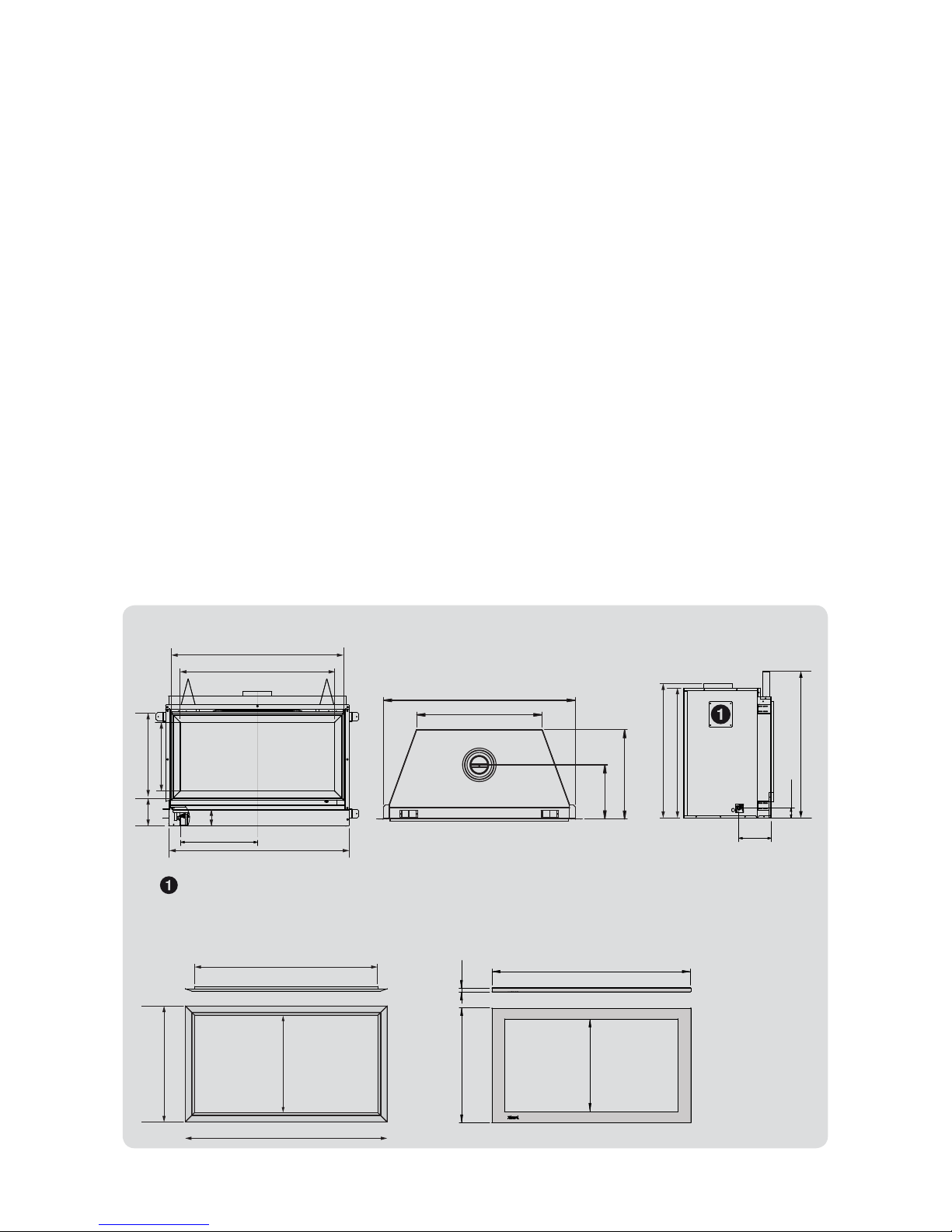
Specication
Dimensions (mm)
668
538
25
1155
Specification summary
Input: 19-33 MJ/h
Output: 3.8-7.5 kW*
Efficiency: 80%
Heating area: up to 116 m
2
**
Gas type: NG or ULPG
A direct vent (natural draft) inbuilt
gas fireplace with a glass front and
convection fan (top discharge).
Operated with a remote control
(7-day programmable timer).
* Will vary according to gas type and flue
configuration
** Will vary depending on geographical
location in NZ
Data plate
Centre front of base panel, behind
the service panels.
Gas connection
½ “ BSP male flare. This connects
straight into the gas control on the
lower left hand side of the unit.
Ignition
Integrated sparker to pilot.
Noise level: 37-45 dB(A)
Flue
Inner 100 mm, outer 170 mm.
Appliance must be installed with a
Rinnai flue system.
Power consumption and
electrical supply
High 50 W
Standby <1 W
Comes with a 1.5 m power cord and
3-pin plug. The standard electrical
connection is to the right hand
side of the appliance.
Safety devices
Light to pilot, delayed ignition,
overheat switch, electronic
flame failure supervision, and
combustion chamber relief.
Temperature control
Thermostatic, temperature control
range 7-32 °C.
Weight: 60 kg
Installation considerations
Maximum flue height is 5.4 m.
Smaller rooms will heat up quickly,
and due to the efficiency of the
appliance, the fire will turn off
once the set temperature has been
reached.
The Symmetry looks and performs
best when installed close to
the floor. If the unit is installed
higher up the wall the movement
of air from the convection
fan, depending on the room
configuration, could create
draughts.
310
1090
715
510
190
60
750
775
845
440
C
L
95
1060
149
400
500
890
995
Cover panel: 150 mm opening on both sides of the heater. Covers are removed only when a Symmetry
Heat Transfer Kit is installed.
1110
643
538
1006ID
Standard metal outer frame Premium flat metal outer frame
RDV3611 installation guide: 11156-E 05-16 | 5
Gas supply
The gas connection from the control valve is a ½ “ BSP
male flare fitting. This connects straight into the gas
control on the lower left hand side of the appliance.
Refer to the dimension diagram for the gas
connection dimensions from the back and centreline
of the unit.
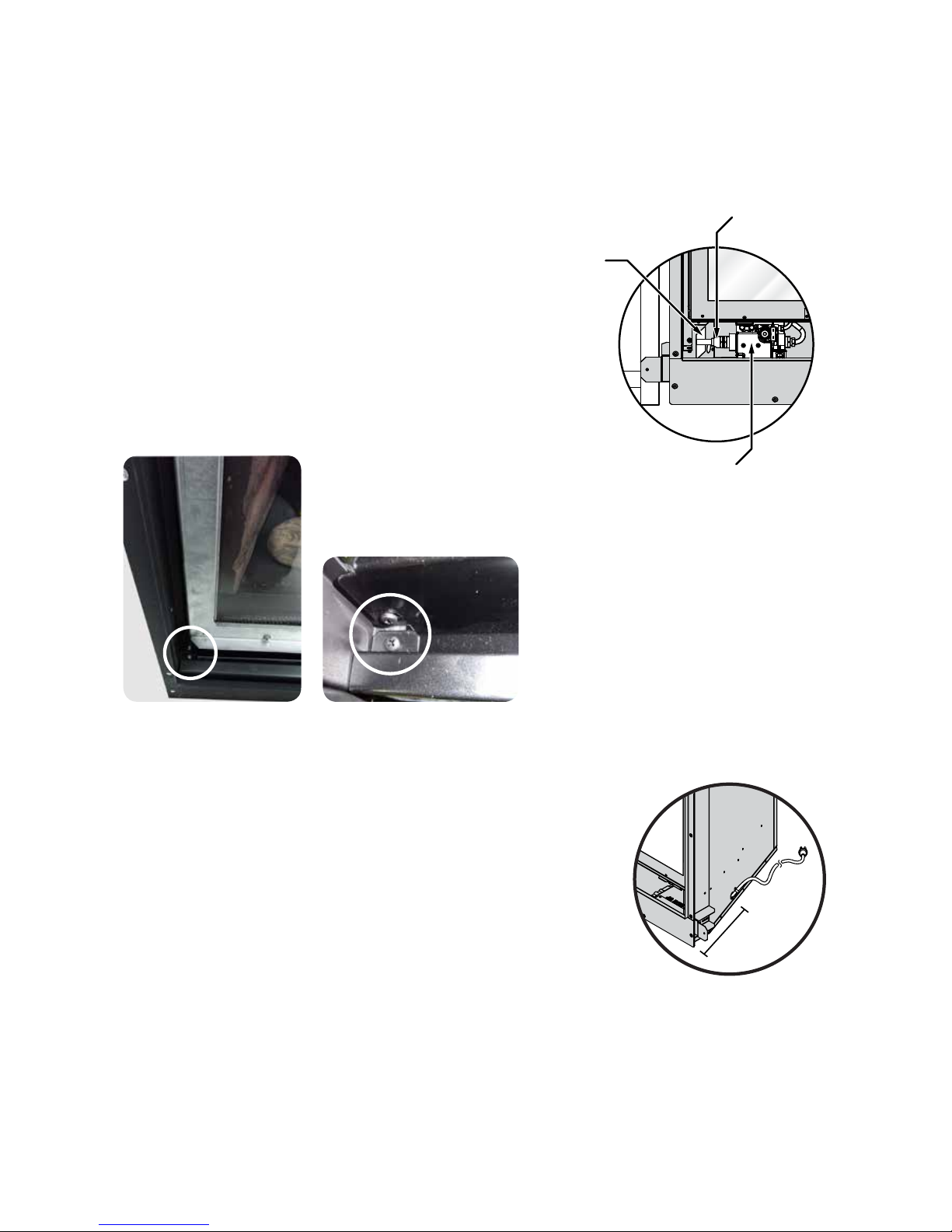
To access the gas connection, remove the upper and
lower bracket (also called the service access panels).
The brackets can be removed by undoing the screws
as shown below at each end of the unit.
Flared union
Connection access
Gas control
Gas pipe sizing must consider gas input to this appliance as well as other gas
appliances in the premises.
Electrical supply
The Symmetry is fitted with a 1.5 m power cord and a 3-pin plug.
The standard electrical connection is to the right side of the front of
the appliance. If necessary this can be changed by an electrician to
terminate on the left.
The connection is either direct wired* or connected to a power point
within the cavity. This must be connected to a dedicated 230 V, 10 A
earthed power point. The electric isolation switch must be accessible
after the appliance has been installed.
The unit must not be located below a power socket outlet (potential fire hazard).
If the supply cord is damaged, it must be replaced by a licensed tradesperson. This must be a
genuine replacement part available from Rinnai, part number 6765B.
* Consult a qualified electrician if direct wiring is required as it must comply with AS/NZS 5601.1 and AS/NZS 3000 and other
relevant local regulations.
250 mm
6 | RDV3611 installation guide: 11156-E 05-16
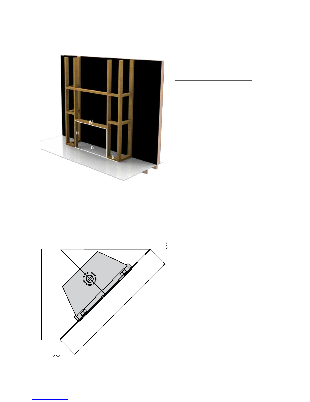
Framing dimensions
The main points governing location are flueing and warm air distribution. The Symmetry has
an integrated zero clearance box that isolates the appliance from combustible materials. This
means it can be installed directly into a decorative fireplace constructed from materials such as
wood or plaster.
Enclosure dimensions
W-width 1100-1125 mm*
H-height 850 mm min.
D-depth 540 mm min.
S - side clearance
* If installing a Symmetry heat transfer
kit allow for an additional 250 mm side
clearance per kit. For example if one kit is
being installed the width would need to be
1350-1375 mm. This additional clearance is
required to ensure the ducting does not
come into contact with the fire.
1830 mm
915 mm
1295 mm
Corner installations
RDV3611 installation guide: 11156-E 05-16 | 7
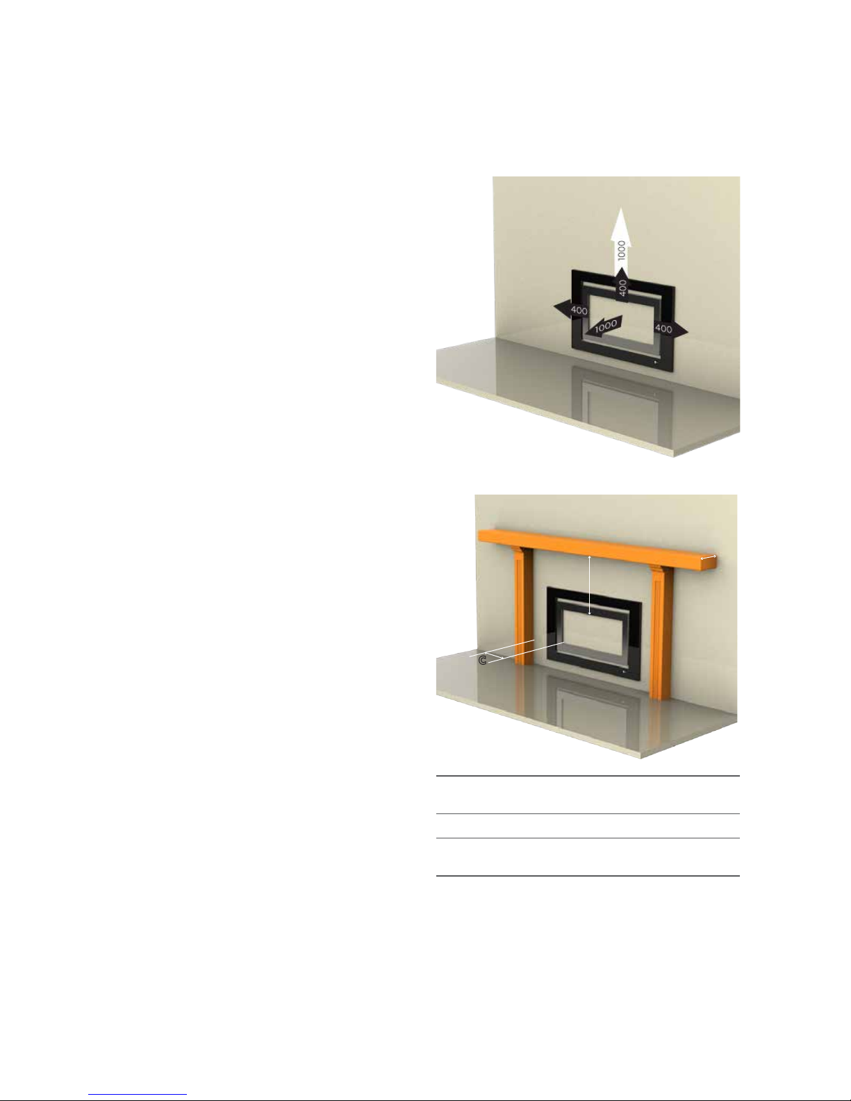
Clearances from combustibles
The clearances listed below, measured from the edge of the inner glass, are
minimum clearances unless otherwise stated.
A
B
C
A Mantel needs to be a min. of 400 mm away from the
edge of the inner glass.
B Max. mantel depth at 400 mm (A) is 250 mm max.
C Surround needs to be a minimum of 400 mm away
from the edge of the inner glass.
For every 50 mm of added mantel depth there must be
an additional 100 mm of clearance from the edge of the
inner glass. For example:
Mantel depth
A
: clearance required
300 mm 500 mm
350 mm 600 mm
400 mm 700 mm
While the heater is operating
The appliance must not be installed where
curtains or other combustible materials could
come into contact with the heater. The 1000 mm
clearance above is the clearance to a ceiling. The
400 mm side clearance includes side walls.
Floor protection
Heat emanating from this fire may over time
affect the appearance of some materials
used for flooring, such as, carpet, vinyl, cork
or timber. This may be amplified if the air
contains cooking vapours or cigarette smoke.
To avoid this occurring, it is recommended
that a mat be placed in front of this appliance.
Mantels and surrounds
Combustible mantels and surrounds require
clearance from the unit to minimise the
risk of fire. Mantels and surrounds, made
of combustible materials such as wood,
are allowed providing they are outside the
minimum clearances shown.
Hearths
A hearth is not necessary but can be used
for decorative purposes or protection of
sensitive flooring if required. A hearth must
not obscure the front of the fire.
Wall surface above the fire
The temperature of the wall surface directly
above the fire may get warm and distort
paint finishes, or distort vinyl wall coverings.
For durability of surfaces, please contact the
manufacturer for their specification.

8 | RDV3611 installation guide: 11156-E 05-16
The below diagram is to assist people who are determining the clearance area
around the Symmetry without having the unit on site.
Glass width
900 mm400 mm 400 mm
600 mm 400 mm
Clearance Clearance
Minimum above fire
Minimum to ceiling
1700 mm
1000 mm
Symmetry 3611
RDV3611 installation guide: 11156-E 05-16 | 9
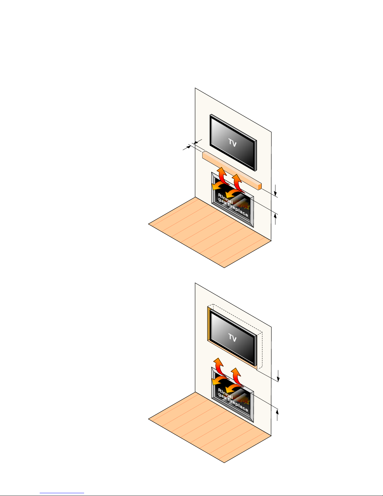
TV installation
The Symmetry has a fan that distributes warm air from the top of the appliance out
into the room. As warm air is dispersed outwards, as opposed to directly upwards,
installation of a TV may be an option.
The diagram shows
recommended clearances
when installing a TV directly
above the Symmetry, or into
a recess. All dimensions are in
millimetres.
400 mm dimension
The 400 mm dimension
is the minimum clearance
required to to a mantel. The
image adjacent shows the
dimension from the edge
of the frame, in the case of
the Symmetry the 400 mm
dimension is to be taken from
the edge of the inner glass.
Always check with the TV
manufacturer
It is up to the owner to check
the TV installation with the TV
manufacturersome have
warranty conditions that state
a TV is not to be installed
above a fireplace.
Rinnai does not accept any
responsibility for damage to
a TV resulting from the use of
this information.
Refer p. 7
400 mm
minimum
400 mm
minimum
10 | RDV3611 installation guide: 11156-E 05-16
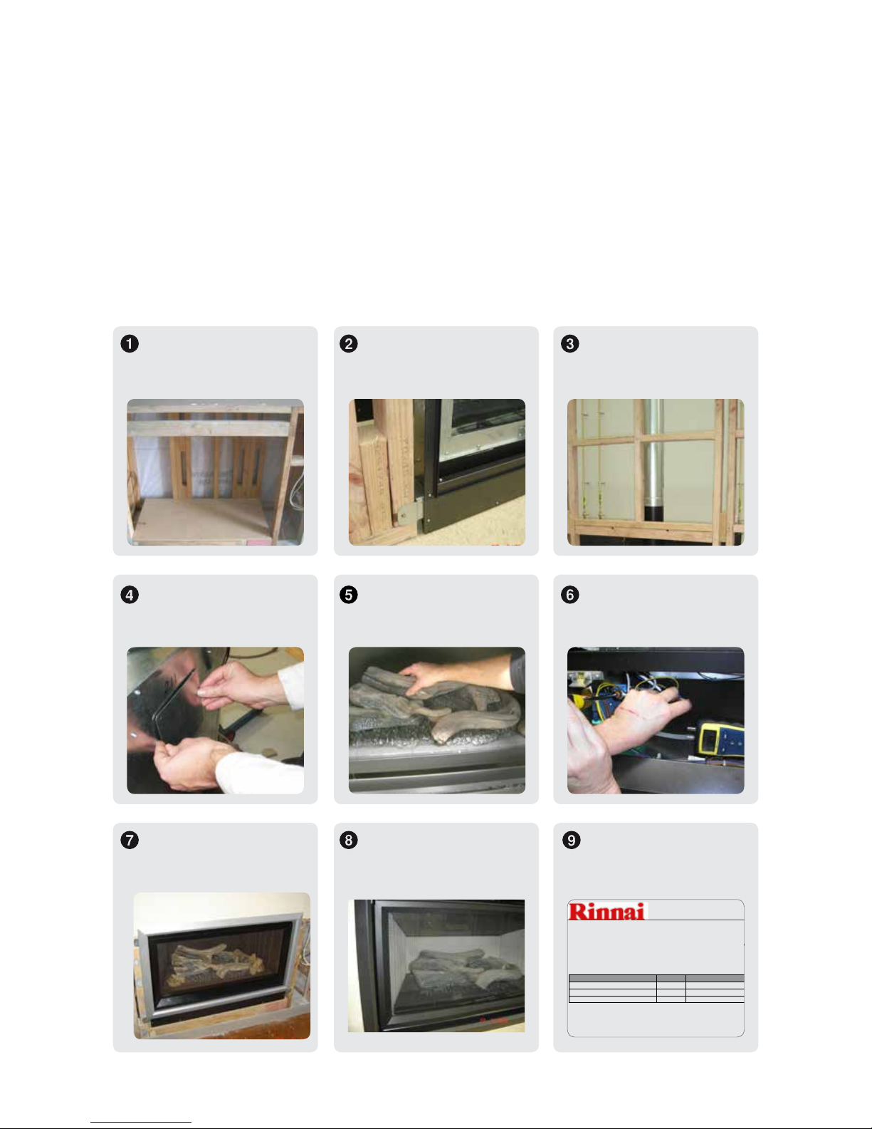
Installation overview
Read these instructions to get an overview of the steps required before starting the
installation. Failure to follow these instructions could cause a malfunction of the
appliance. This could result in serious injury and/or property damage.
Unpack the appliance and components, and check for damage. Do not install any
damaged parts. Check all components have been supplied and that you have the
correct gas type.
Build the frame and
complete the electrical
connection.
Install mounting brackets,
the Symmetry unit, and fix
the unit to the frame.
Install the flue and
complete the gas
connection.
Install ducting kit, if
purchased—separate
instruction.
Install flue restrictor (if req.)
and log set.
Test pressures and establish
flame pattern.
Install cladding, refer
importantant note on p. 18.
Install frames. Commission unit and
uprate if an LPG unit with a
vertical termination.
RDV3611 : SYMMETRY
Vertical Flue Up Rating Instructions (ULPG ONLY)
Must be installed by a certified gas fitter in accordance with all applicable local rules and regulations
The Rinnai Symmetry RDV3611 LPG appliance is factory supplied, with rated input of 30MJ/hr for
installation for Horizontal Vent Terminations only. To ensure that optimum Flame Effect and
Maximum Energy Efficiency is obtained when the unit is being installed with a Vertical Vent
Termination the appliance must be up rated to 33MJ/hr by installing this Kit.
Kit Contents
Quantity
Rinnai Part Number
Comments
Main Injector 1 11534
1.70mm
Data Plate 1 11152
For Vertical Flues ONLY
Instruction Sheet 1 11154
Gas Up Rating Procedure
1. Remove Glass assembly 4 x screws; lift and remove.
2. Remove service panel front 2x screws.
 Loading...