

Rinnai Smart Box SBOXI, Smart Box SBOXC, Smart Box SBOXF Installation Instructions Manual
Smart Box® Installation Instructions
Securing the Smart
For Recess Enclosure SBOXI / SBOXC & Semi- Recess Frame SBOXF
To suit Rinnai REU water heater models: 1220 | 1620 | 2024 | 2426 | 2626 | 2630
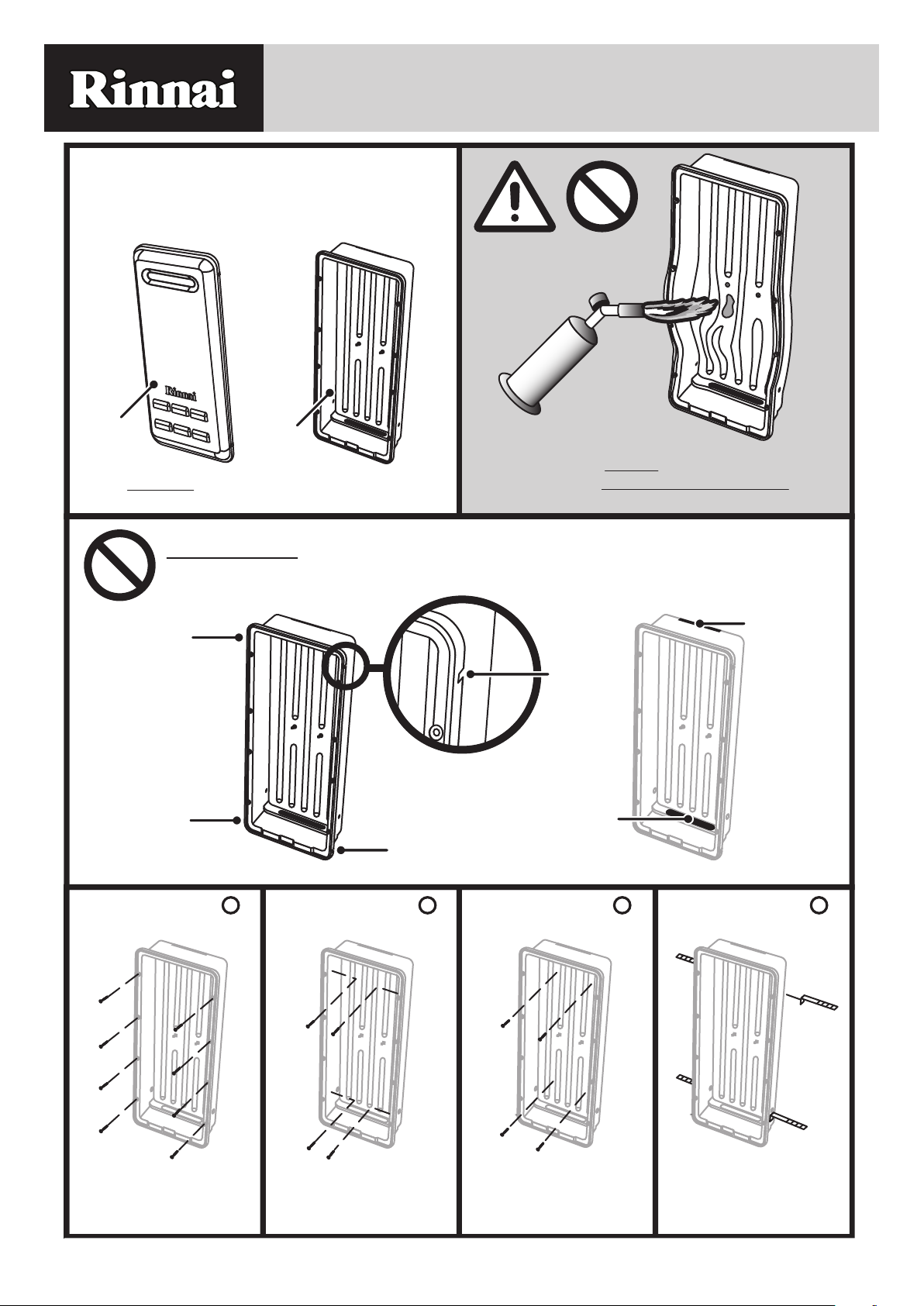
The Smart Box® (SBOX) Recess Enclosure
system is made up of two (2) components
these are the SBOXI (insert) and SBOXC
(cover). These are packed together in the one
carton.
SBOXC
SBOXI
If you DO NOT have a SBOXC (cover) for your
Smart Box contact your supplier.
DO NOT
Obstruct the slots provided for the Cover Clips, Support Bracket or Pipe Access
Cover
Clip
Slot
Cover
Clip
Slot
Cover
Clip
Slot
Take care to AVOID exposing Smartbox
components to ANY EXCESSIVE HEAT when
welding pipes.
Support
Bracket
Slot
Cover
Clip
Slot
Pipe
Access
Slot
Securing Method
Securing the Smart
Box Insert externally
Rinnai 1 SMART BOX IM
A
Securing Method
Securing the Smart
Box Insert internally
through the side wall
B
Securing Method
Securing the Smart
Box Insert internally
through the rear wall
C
Securing Method
Box Insert with the use
of brick ties
D
WARNING
The Smart Box and water heater MUST be installed in accordance with manufacturers instructions,
NOTE
IMPORTANT
AS/NZS3000, AS/NZS3500 and AS/NZS5601. Local gas authorities may have additional local
requirements. As an example, some gas authorities require a minimum vertical clearance of 500mm or
more between the top of a gas meter and the air intake grille on the Smart Box Cover. Conrm all local
requirements prior to installation. Ensure any electrical wiring or plumbing pipework situated behind
the Smart Box are not damaged as a result of Smart Box installation.
SMART BOX® RECESS ENCLOSURE COMPONENTS
SBOXI (Insert) and SBOXC (Cover).
GENERAL PREPARATION
1. Prepare an opening in the wall approximately 1 metre above the ground.
The opening requirements are Height 1030 mm, Width 390 mm and a
minimum Depth of 160mm (see dimension diagrams page 3). Ensure the
location complies with the requirements of AS/NZS 5601 Fig. 6.2.
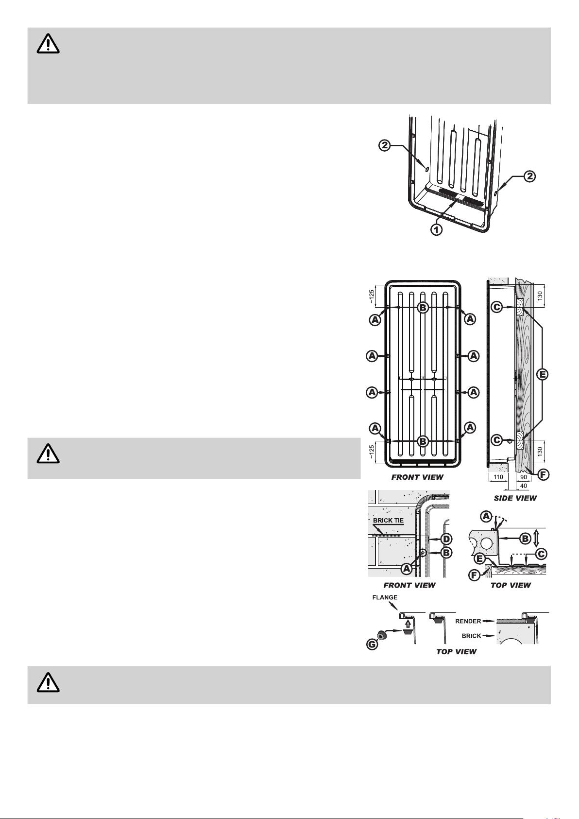
2. Remove the transport tab (1) from the pipe entry point of the Insert.
3. Determine the appropriate electrical access point and remove either the
left or right the knock out plug (2)located near the bottom of the side
walls of the Insert.
SECURING OPTIONS
The Smart Box Insert is designed to be surface mounted and may be
secured using one of the following methods:
(A) Securing the Smart Box Insert externally
Secure to the wall surface via the 8 screw holes provided in the ange of the
Insert using suitable fasteners.
(B) Securing the Smart Box Insert internally, through the side wall
Secure the Insert into a solid xture such as brickwork, timber studs etc,
through the side walls using suitable fasteners.
At least two fasteners should be used through each side wall approximately
125 mm from the inside top and bottom horizontal faces of the Insert.
Excess space between the side walls of the Insert and the
solid xture may require packing to prevent distortion of the
Insert.
(C) Securing the Smart Box Insert internally, through the rear wall
Install two noggins (E) between wall studs (F), these are to be centred at
130 mm from the top and bottom of the opening. Secure the Insert into the
noggins (E) through the rear wall using suitable fasteners.
(D) Securing the Smart Box Insert with the use of a brick tie
Secure a brick tie to the side walls of the Insert with pop-rivets or screws.
As the brickwork is being laid use the attached brick ties to secure the Insert
into the brick courses. Use two brick ties per side, one near the top and
bottom of the Insert.
(G) Installing the Smart Box to rendered surfaces
Use spacers (G) (not provided) to install the Smart Box Insert, with sucient
clearance for rendering.
When the render is applied ensure that the gap provided by the stand-o spacers is NOT exceeded as
this will prevent the Smart Box Cover from being tted!
Rinnai 2 SMART BOX IM
 Loading...