

Rinnai Slimfire Zero Clearance Box Instructions Manual
RINNAI SLIMFIRE Zero Clearance Kit
If the heater is to be installed into a combustible opening,
Parts included in the Zero Clearance kit are:
1 Top panel
1 Base panel
2 Side panels
1 Rear panel
1 Flue adaptor
2 Base support runners
1 Plinth
1 pkt screws
1 Slip Socket
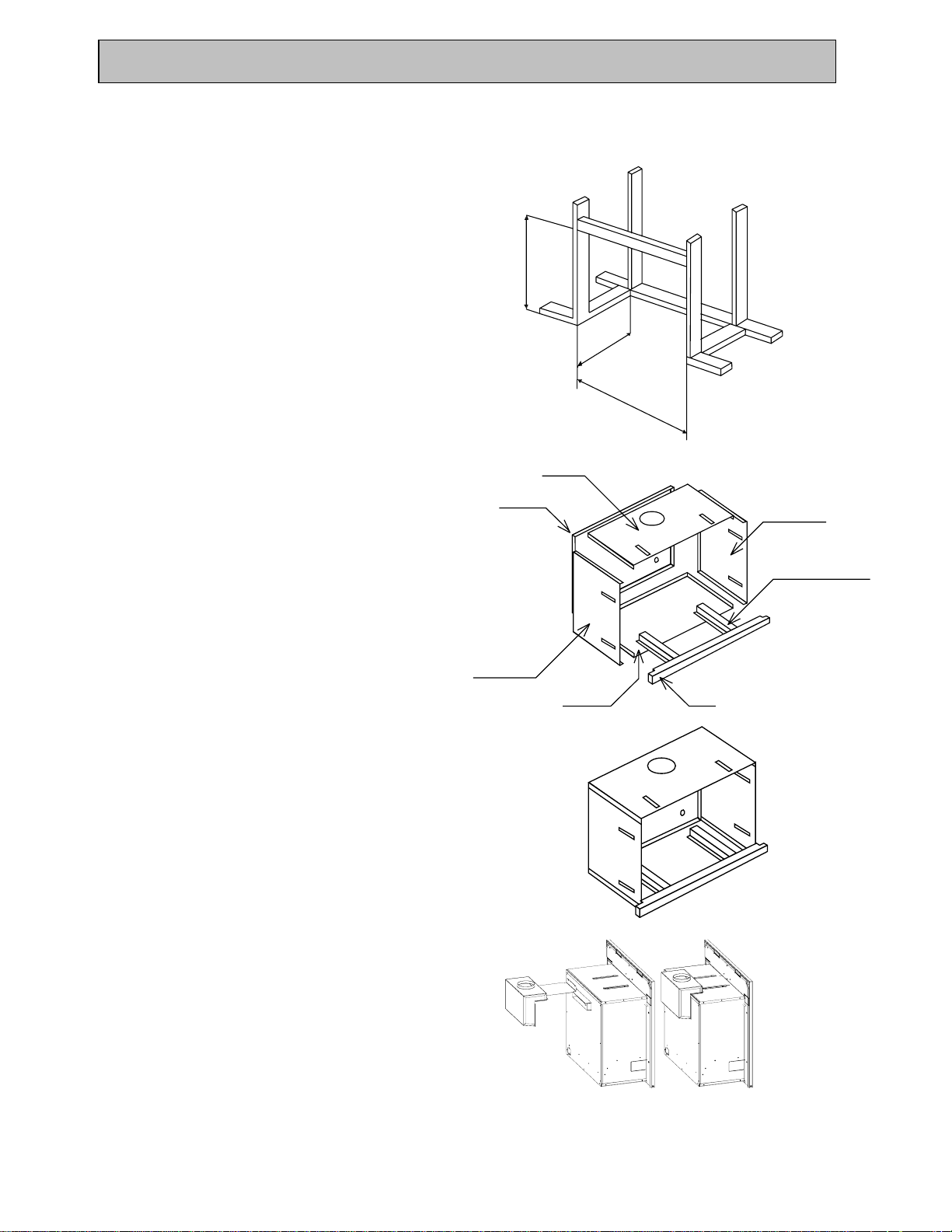
Build frame as set out in (Fig.1).
Lay the base panel on the floor with return fold upward.
Stand side panels on the outside of the base panel
with the securing fold to the front as shown in (fig.2).
Slide rear panel between side panels, ensuring that the
gas inlet hole is in the bottom right-hand corner.
the Rinnai Zero Clearance Kit ZEROS must be used.
675 mm
Rear Panel
Top Panel
370 mm
685 mm
Fig.1
R/H Side Panel
Base Support Runners
Place the top panel with the return fold forward, with
the flue outlet to the rear.
The Zero Clearance Box should now be stable enough
on its own to secure the self-tapping screws in the
holes provided. (Fig. 3)
Run the gas line to the appropriate position.
The Zero Clearance Box can now be secured to the
framing using the holes provided.
Securely connect the flue adaptor to the rear of the
slimfire heater (Fig.4).
L/H Side Panel
Base Panel
Plinth
Fig.2
Fig.3
Fig.4
Slimfire 25 Zero Clearance Box 10/06/2003
1
RINNAI SLIMFIRE Zero Clearance Kit
Only the FLFKIT02 and FLFKIT03 can be used in
conjunction with the Zero Clearance Box
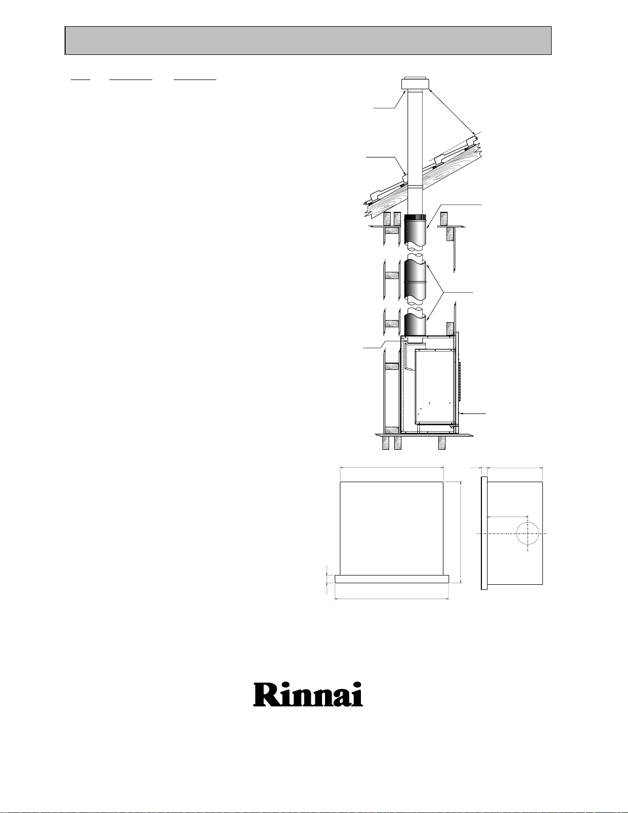
Check roof space for any flue obstructions. If the
required clearance from flue to combustible material
cannot be obtained (25mm), The flue can be offset
with the use of two 45°Bends (FLFBEND).
Install the double-lined flue with 150mm black outer
section to penetrate 30mm through the hole the Zero
Clearance Box, and the inner section to penetrate
50mm. Note: Ensure the flue is fully supported
independently of the appliance AS5601/AS601 Clause
5.13.4.2 and 5.13.4.3
When the heater is installed the slip collar is used to
connect the heater to the flue.
This installation is designed to ensure that any residual
heat in the Zero Clearance Box is ducted away up in
the cavity between the inner and outer flue pipes.
Extend the flue outer to terminate in the roof space and
the inner flue pipe to atmosphere in accordance with
AS5601/AS601 Clause 5.13.6.
For single story installations use flue kit FLFKIT02
(Fig.5).
For two story installations use flue kit FLFKIT03
This appliance shall be installed in accordance with:
• Manufacturer’s Installation Instructions
• Local Gas Fitting Regulations
• Municipal Building Codes
• A.G.A. Installation code AG601/AS5601/ Gas Installations
• Any other local relevant Statutory Regulation
Installation & Service must be performed by an
authorised person.
CHIMNEY
COWL
SINGLE SKIN
CLEARANCE
FROM
COMBUSTIBLE
25 mm
SLIP
SOCKET
100 mm
Minimum
Clearance
500 mm
TWIN SKIN
CLEARANCE FROM
COMBUSTABLE 10 mm
TWIN SKIN
LENGTH
1000 mm x 2
SLIMFIRE
HEATER
Fig.5
680
50
750
40 365
266
670
For further information please call the Rinnai Australia Technical Helpline
1300 366 388
Slimfire 25 Zero Clearance Box 10/06/2003
2
 Loading...