

Rinnai RIBF2N, RIBF2L, SLIMFIRE 252 Operation & Installation Manual
This appliance shall be installed in accordance with:
All Rinnai gas products
are A.G.A. certified.
SLIMFIRE 252

Rinnai Australia i Slimfire 252 Operation & Installation Manual
Congratulations on the purchase of your Rinnai Slimfire 252 gas log flamefire.
We trust you will have many years of comfort and enjoyment from your appliance.
BEFORE PROCEEDING WITH THE OPERATION OR INSTALLATION OF YOUR NEW HEATER
PLEASE READ THIS MANUAL THOROUGHLY AND GAIN A FULL UNDERSTANDING OF THE
REQUIREMENTS, FEATURES AND OPERATION OF YOUR NEW APPLIANCE.

Rinnai Australia ii Slimfire 252 Operation & Installation Manual
BEFORE YOU START .......................................................................................................................................... 1
INSTALLATION REQUIREMENTS..................................................................................................................... 1
CERTIFICATION................................................................................................................................................. 1
CARTON CONTENTS / ITEM CHECKLIST........................................................................................................ 1
INSTALLATION RECORD.......................... ... .... ... ... ... ... .... .......................................... ... ... ... .... ... ......................... 2
SAFETY DEVICES.............................................................................................................................................. 5
ABOUT YOUR HEATER ....................................................................................................................................... 6
GENERAL DESCRIPTION.................................................................................................................................. 6
DESIGN FEATURES........................... ... ... ... .......................................... .... ... ... ... ... .... ... ... ... ................................ 6
OPERATION.......................................................................................................................................................... 7
TO TURN YOUR HEATER ON ........................................................................................................................... 7
ADJUSTING HEAT.............................................................................................................................................. 7
FAN OPERATION............................................................................................................................................... 7
TO TURN YOUR HEATER OFF ......................................................................................................................... 7
POWER OUTAGES ............................................................................................................................................ 7
CARE AND MAINTENANCE................................................................................................................................. 8
TROUBLE SHOOTING CHECKLIST .................................................................................................................. 8
SERVICE............................................................................................................................................................. 8
ABNORMAL FLAME PATTERN.......................................................................................................................... 9
TABLE OF CONTENTS - INSTALLATION......................................................................................................... 10
ABNORMAL FLAME PATTERN........................................................................................................................ 27
CONTACT INFORMATION ................................................................................................................................. 33
TABLE OF CONTENTS - OPERATION
Rinnai Australia 1 Slimfire 252 Operation & Installation Manual
BEFORE YOU START
INSTALLATION REQUIREMENTS
This heater must be installed by an authorised person. The installation must conform to local regulations.
The installation must also comply with the instructions supplied by Rinnai.
Service and removal must be carried out by an author i sed pe rso n .
CERTIFICATION
The Rinnai Slimfire
®
has been certified by the Australian Gas Association.
The AGA Certification Number is shown on the appliance dataplate.
No parts or functions should be modified or permanently removed from the heater.
Please keep these instructions in a safe place for future reference.
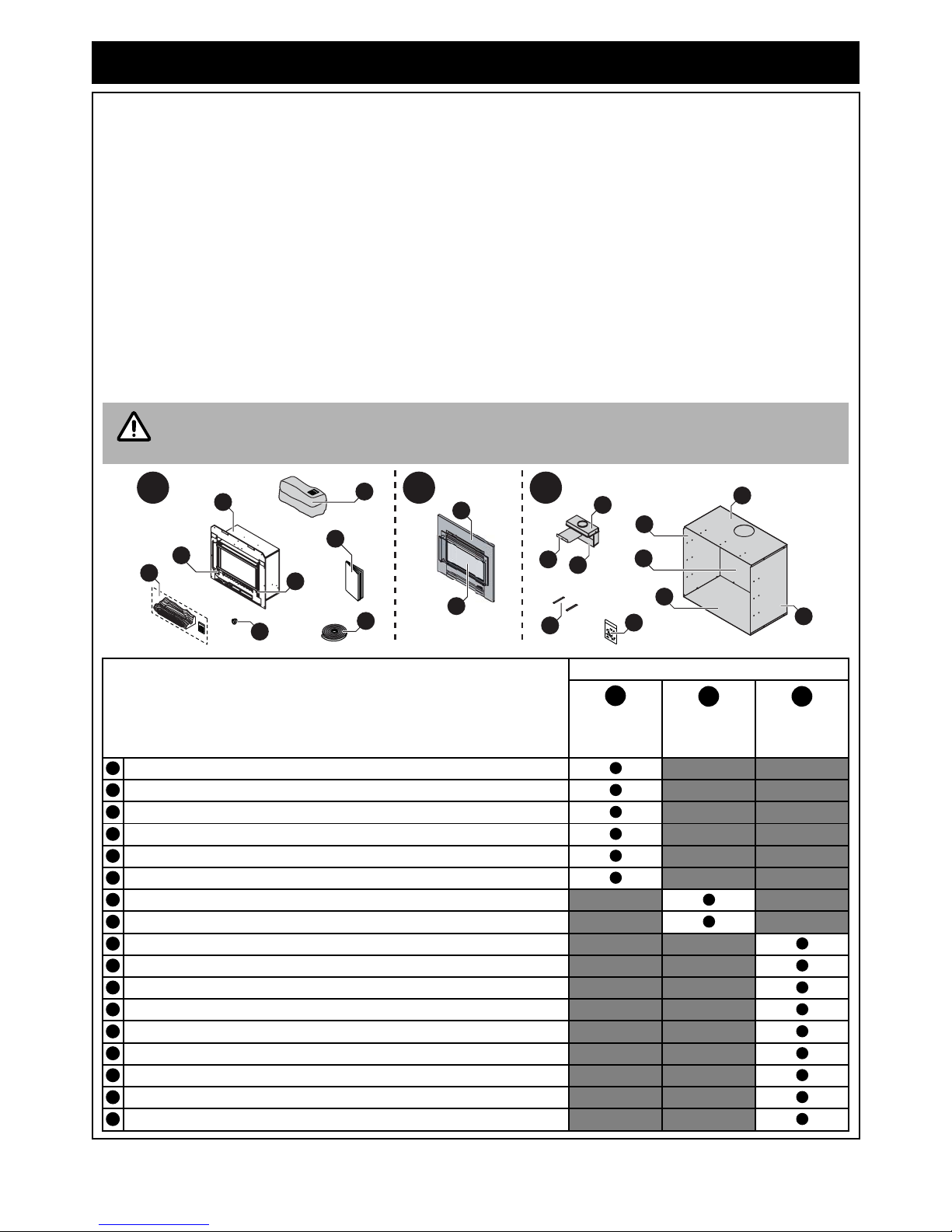
CARTON CONTENTS / ITEM CHECKLIST
The components for Slimfire 252 heater are supplied in separate cartons, the following tables list which
components are in each carton. Ensure that the components listed for the installation method being installed are
present before proceeding with the installation.
The Engine and Fascia are packed into two separate cartons and are required for all installation
types. Masonry installations may require a flexiliner flue to be installed, refer to “MASONRY FLUE
INSTALLATION” on page 17 for details. The Zero Clearance Kit and flue are purchased separately.
Component Descriptions
Carton Contents
Engine Fascia
Zero
Clearance Kit
Rinnai Slimfire 252 Engine.
Artificial log set / burn media, Satchel burner granules (packed on top of the engine).
½” BSP Flared nut (x1shipped inside engine, attached to gas connection).
Adhesive backed foam sealing strip.
Operation and Installation manual.
Fascia Mounting Screws (x2 pre-installed in the engine fascia mounting brackets).
Fascia.
Glass dress guard.
Transition box rails (x2).
Transition box upper.
Transition box lower.
Transition box guide plate.
Zero Clearance Box - Top panel.
Zero Clearance Box - Base panel.
Zero Clearance Box - Rear panel.
Zero Clearance Box - Left & Right side panels.
Packet assembly screws, rivets and grommet.
IMPORTANT
5
4
A B C
11
2
1
5
2
16
13
16
14
15
12
10
17
7
8
9
3
6
6
A
B
C
123
4
567
8910111213141516
17

Rinnai Australia 2 Slimfire 252 Operation & Installation Manual
INSTALLATION RECORD
INSTALLERS / GAS FITTERS DETAILS
Installers Name: ____________________________________________________________________
Company Name: ____________________________________________________________________
Company Address: ____________________________________________________________________
____________________________________________________________________
____________________________________________________________________
Company Contact Details
Telephone: ____________________________________________________________________
Mobile Phone: ____________________________________________________________________
Certificate of Compliance / Certification Number: _____________________________________________
Authorised Persons - Licence Number: _____________________________________________________
Installers Signature: ____________________________________________________________________
Installation Date: ____________________________________________________________________
APPLIANCE DETAILS
Model Number: ____________________________________________________________________
Serial Number: ____________________________________________________________________
Installation Address: ____________________________________________________________________
____________________________________________________________________
____________________________________________________________________
____________________________________________________________________
THIS APPLIANCE MUST BE INSTALLED, SERVICED
AND REPAIRED BY AN AUTHORISED PERSON.
Rinnai Australia 3 Slimfire 252 Operation & Installation Manual
SAFETY
• Failure to comply with these instructions could result in a fire or explosion, which could cause
serious injury, death or property damage.
• Improper installation, adjustments, service or maintenance can cause serious injury, death or
property damage. Such work must be performed by an authorised person.
• The appliance must be installed in accordance with the local gas and electrical authority
regulations.
• Flue terminal must always vent directly to outdoors.
• DO NOT extend the flue vertically or horizontally in ways other than prescribed in the appliance
manufacturers’ installation instructions.
• For information on gas consumption, see data plate on the appliance.
• This appliance must not be instal led whe re cu rtains or other combustible materials could come
into contact with it. In some cases curtains may need restraining.
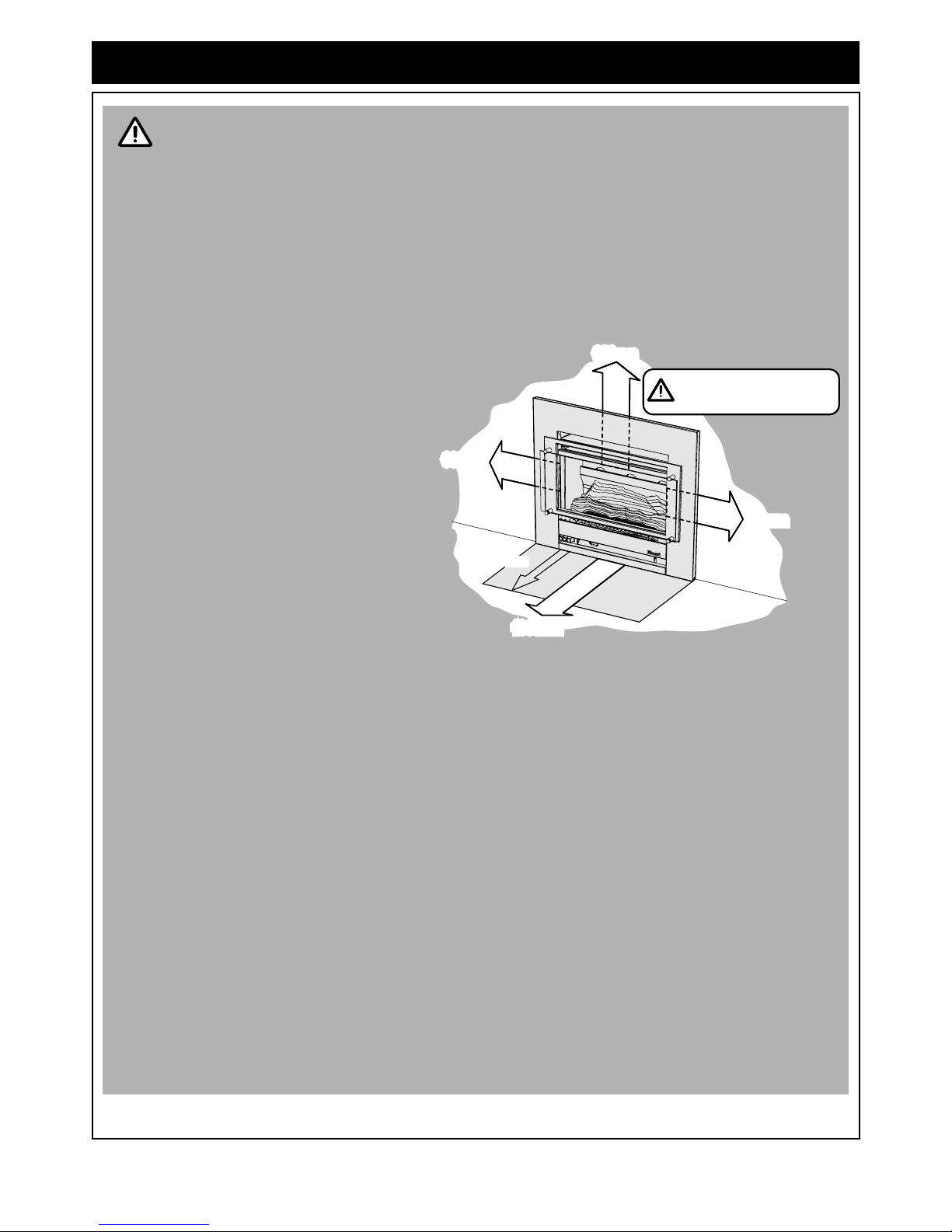
• WARNING: This heater MUST NOT
be used if either of the glass
panels are damaged.
• When considering installation
ensure minimum clearances as
follows are adhered to, refer Fig. 1.
• Heat radiating from the front of this
heater may over time affect the
appearance of some materials
used for flooring such as carpet,
vinyl, cork or timber. This effect
may be amplified if the air in the
room contains cooking vapours or
cigarette smoke. To avoid this
possibility, it is recommended that
a mat or similar protective sheet be
placed in front of the appliance,
extending at least 750 mm in front
of the glass guard.
• This appliance is not intended for use by persons (including children) with reduced physical,
sensory or mental capabilities or lack of experienc e and knowledge, unless they have been give n
supervision or instruction concerning use of the appliance by a person responsible for their
safety.
• The appliance is not intended for use by young children or infirm persons without supervision.
• Young Children must be supervised when in the vicinity of this heater while it is in operation.
• The Glass Dress Guard MUST be fitted to this appliance to reduce the risk injury from serious
burns and no part of it should be permanently removed.
• For protection of young children or the infirm a secondary guard is required.
• If the supply cord is damaged or requires replacing, it must be replaced by the manufacturer or
the manufacturer's agent or similarly qualified person in order to avoid a hazard.
• The heater must not be located immediately below a power socket outlet.
• DO NOT connect to an LPG Gas cylinder indoors.
• A dedicated 240 V earthed 10 Amp power point must be used with this appliance.
• DO NOT modify this appliance. Modifying from original specifications may create a dangerous
situation and will void your warranty.
• Only the flue components specified by Rinnai must be used.
• Unpack the heater and check for damage. DO NOT INSTALL A DAMAGED HEAT ER. If t he hea te r
is damaged, contact your supplier for advice.
• Before installing the heater, check the label for the correct gas type (refer data plate, inside the
appliance).
• Refer to local gas authority for confirmation of the gas type if you are in doubt.
• This heater must be installed by an authorised person.
WARNING
Note that side and vertical
clearances are measured
from the edge of the glass.
300mm
300mm
300mm
750mm
1000mm
Fig .1

Rinnai Australia 4 Slimfire 252 Operation & Installation Manual
SAFETY
The appliance is not intended for use by young children or infirm persons without supervision.Young children
should always be supervised to ensure that they DO NOT play with the appliance.
DO NOT sit or lean against the heater.
DO NOT allow children or elderly persons to sleep in the warm air discharge from the heater.
DO NOT post or allow children to post articles into the louvres of the heater.
DO NOT cover or place articles on this heater.
DO NOT place articles in front of the louvres.
DO NOT operate / install this heater in area s where painting is taking place, or in places such as hairdressing
salons, where there may be fluff and dust, and where aerosols are used.
DO NOT place articles on or against this appliance.
DO NOT use or store flammable materials near this appliance. Keep flammable materials away from heater.
Combustible materials MUST NOT be placed where the heater could ignite them.
DO NOT spray aerosols in the vicinity of this appliance while it is in operation. Most aerosols contain flammable
substances which can be a heater hazard if used near this heater when it is in use.

Rinnai Australia 5 Slimfire 252 Operation & Installation Manual
SAFETY
A dedicated 240V earthed 10 Amp power point MUST BE USED with this appliance.
DO NOT use power boards or double adaptors to operate this appliance. Th e heater MUST NOT be loca ted below
a power socket-outlet.
DO NOT unplug the heater while it is in operation or while the fan is still cycling.
DO NOT place containers of liquid on top of the heater. Water spillage can cause extensive damage to the
appliance and create an electrocution hazard.
DO NOT place articles on or against this appliance.
DO NOT connect to an LPG gas cylinder indoors.
.
Turn the heater ‘OFF’ after use.
DO NOT remove the Glass Dress Guard. The dress guard is fitted to this appliance to reduce the risk of fire or
injury from burns and no part of it should be permanently removed. For protection of children or the infirm, a
secondary guard is recommended.
Heat emanating from the front of the appliance may over time affect the appearance of some materials used for
flooring such as carpet, vinyl, cork or timber. This affect may be amplified if the air in the room contains cooking
vapours or cigarette smoke. To avoid this possibility, it is recommended that a mat be placed in front of the
appliance, extending at least 750 mm in front of the heater.
When the heater is operated for the first time or after long period s of non use a slight odou r may be emitte d, this is
normal. However if odours persist switch ‘OFF’ the appliance and contact Rinnai.
SAFETY DEVICES
Over Heat Switches: When the heater gets too hot during operation (for example when air outlet louvres are
blocked, or during a power outage) these devices turn the gas o ff automatically and allow the heater to restart when
cooled down.
Electrical Fuse: The electrical circuits are protected by a fuse.
Flame Failure Sensing System: Automatically cuts off the gas supply to the heater in the event of a flame failure.
Power Failure: In the event of a power failure while the heater is in operation the fan will stop, however the gas
valves remain open and continue to heat the appliance. The overheat protection may then shut off the gas to
protect the heater, however switching the hea ter to its lowest setting may allow the he ater to continue operating
without reaching an overheat condition.
Rinnai Australia 6 Slimfire 252 Operation & Installation Manual
ABOUT YOUR HEATER
GENERAL DESCRIPTION
Your Slimfire is a burning log effect, gas space heating appliance with natural draft combustion system, intended
for use with Natural Gas and Propane. The burning log effect is achieved using two main bur ners with strategically
placed, 'life like', imitation logs and granules. Temperature control is ach ieved through manual push button control.
This heater has an electronic ignition. The pilot is only on when the heater is in operation.
Burner, logs and granules are contained in a glass fronted, sealed burner box.
Combustion air is drawn from the room. Combustion product is exhausted via the flue discharge vent when
installed in a masonry chimney or wh en installed in a zero clearance box thro ugh a 100mmØ x 150mmØ twin
skinned flue to the outside of the house.
1. Fireplace / Masonry installation - Engine:
The appliance is directly mounted into an existing masonry fire place or a non-co mbustible/masonry en closure
that has a chimney. When installed correctly the appliance is a flush to wall mount.
2. Zero Clearance installation:
The appliance is fitted within a sheet metal Zero Clearance Box Assembly that has been installed into a wall or
other suitable structure. Materials need not be non-combustible. When installed correctly the appliance is a
flush to wall mount.
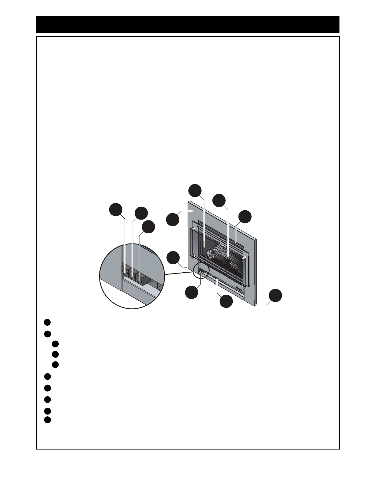
DESIGN FEATURES.
Rinnai Slimfire Heater
Push button control panel
Ignition / Low button
Medium button
High button
Glass dress guard
Flame window - artificial log set and burn media
Warm air discharge vent
Return air vent
Alternative power cable outlet location on front panel can be left or right handed
7
a
b
c
3
2
1
4
5
6
7
1
2
a
bc34567

Rinnai Australia 7 Slimfire 252 Operation & Installation Manual
OPERATION
TO TURN YOUR HEATER ON
ADJUSTING HEAT
The Slimfire has three heating settings LOW , MEDIUM and HIGH .
Press each of the control buttons in order from right to left, this will ignite additional burners and modulate the fan
speed as shown in diagram below.
FAN OPERATION
The fan will operate automatically when the heater warms up, and will stop when the combustion chamber cools.
When the heater is on the ‘high’ setting the fan will operate on high speed when the heater is hot.
When the heater is on the’ low’ or ‘medium’ heat setting, the fan will oper ate on slow speed when the heater is hot.
When the heater is on its lowest setting the fan may turn off as the heater cools and restart when warm again.
The fan may continue to operate o n slow speed w hen the burners have been extinguished until the heater cools
down.
TO TURN YOUR HEATER OFF
To turn the heater ‘OFF’ push and release any of the operated control buttons from left to
right in sequence until all are released.
POWER OUTAGES
BEFORE PROCEEDING ENSURE THE GAS AND ELECTRICITY ARE TURNED ON.
You must read and understand these instructions fully before operating the heater.
The push button controls are located on the front lower left hand side of the heater.
Step 1. Press the right hand control (Ignition/Low) button firmly. This
operates the built-in safety device and starts the electronic spark. The
front burner and pilot will ignite. Check that the burner has lit and
continue to hold the button down for up to 15 seconds. The spark will
continue while the button is held down.
Step 2. If the burner does not remain alight, Push the Ignition/Low
button again and release it. This will return it to the ‘OFF’
position. Wait 30 seconds, then repeat the ign itio n p rocedur e.
The Ignition/Low button
MUST BE in the ‘OFF’ position
before attempting re-ignition.
There is no need to hold the buttons for 15 seconds when adjusting the heat.
The relationship between the burner operation and the fan speed are preset and can not
be independently adjusted.
BUTTON
INGITION/LOW MEDIUM HIGH
FAN SPEED LOW LOW HIGH
FRONT BURNER HIGH HIGH HIGH
REAR BUNER OFF LOW HIGH
MJ/h Usage
Natural Propane Natural Propane Natural Propane
7.7 9.0 14.2 15.8 25.0 25.0
If there is a power failure when the heater is in operation the ov erheat prot ection may s hut off t he
gas to protect the heater. In the event of a power failure, tu rning the heater to its lowest setting may
allow the heater to continue operating without overheating. The fan will not work witho ut electrical
power.
NOTE
a
HIGH MED
IGN
~
LOW
a
c
b
a
NOTE
a
abc
NOTE
a
a
b
c
bc a
NOTE
Rinnai Australia 8 Slimfire 252 Operation & Installation Manual
CARE AND MAINTENANCE
Your heater needs very little maintenance, but the following information will help you to keep it looking good and
working efficiently.
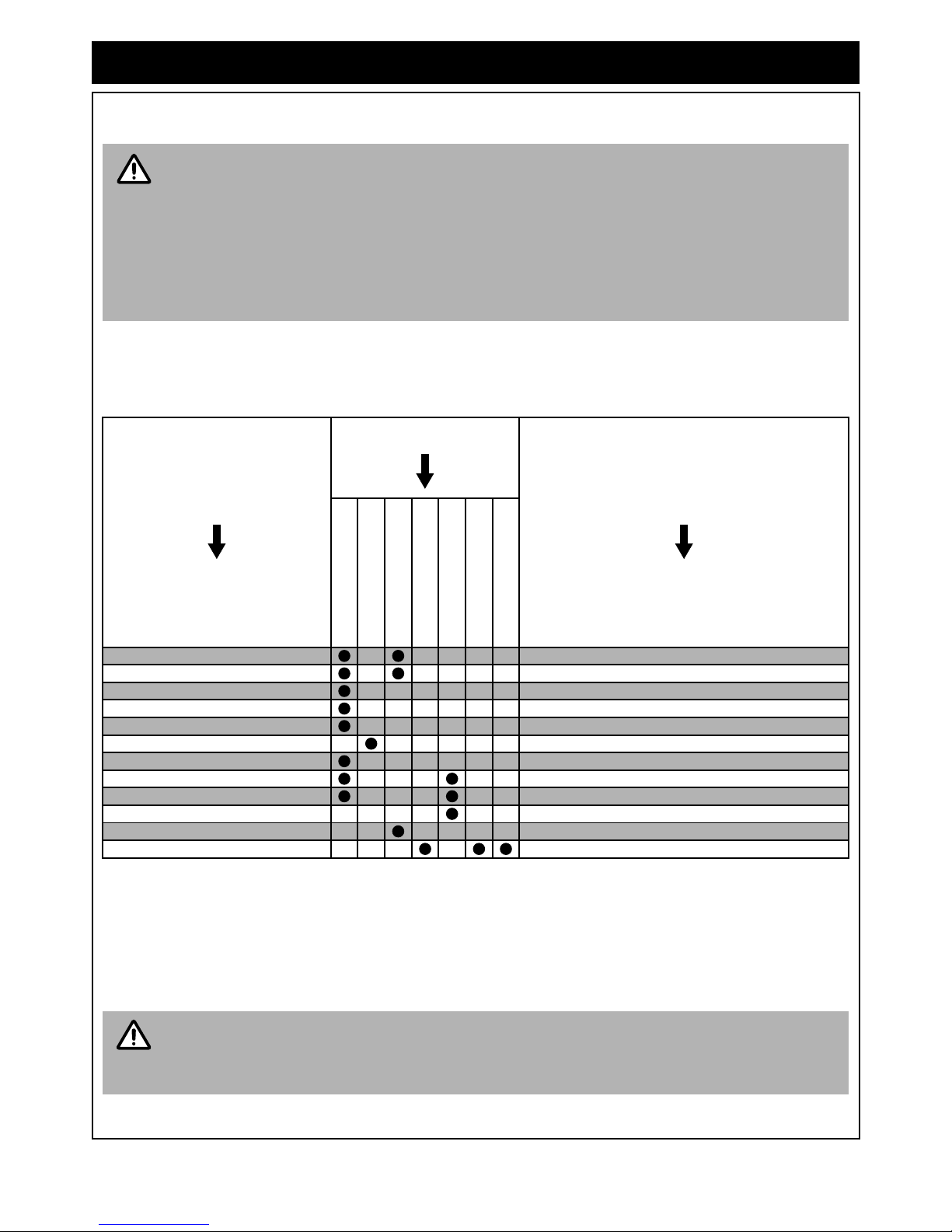
TROUBLE SHOOTING CHECKLIST
Use the following chart to help determine whether a service call is required, however if you are unsure about the
way your heater is operating, or if you have any other faults or problems, please refer to your installer or a Rinnai
Customer Care Centre Consultant, see back page for Rinnai contact details.
SERVICE
Rinnai recommend that this appliance and installation be inspected and serviced every 2 yea rs or more frequently.
If the power supply cord or any other component of the heater are damaged, they must be replaced by Rinnai or
a suitably qualified person.
Any service or repair work should only be carried out by an authorised person. Rinn ai has service and spare parts
departments nationally. See back cover for contact details.
DO NOT attempt to clean the heater while the appliance is hot or operating.
All parts of the heater can be cleaned using a soft, damp cloth.
DO NOT use solvents or abrasives to clean any parts.
DO NOT spray aerosols in the vicinity of the heater whilst in operation.
DO NOT place articles on or against this heater.
DO NOT store flammable materials near this heater.
DO NOT remove any panels or attempt to carry out any service work other than that mentioned in
the “TROUBLE SHOOTING CHECKLIST” below.
Probable Cause
Fault Condition
Simplest Possible Remedy
Burners fail to ignite
Smell of gas
Fan Not Working
Minor soot deposits
Severe sooting
Glass, Condensating
Glass, Streaky lines
Not plugged in or turned off Plug in power cord and turn power ‘ON’.
Mains power failure Turn heater to LOW or OFF until power returns.
(Initial Install) Air in gas pipe Installer to purge air from gas supply.
Air in hose Repeat Ignition procedure.
Ignition failure Repeat Ignition procedure.
Gas escape Isolate gas supply, call Rinnai.
Gas supply turned off Turn gas supply on at the meter or cylinder.
Inadequate flue system Call Rinnai.
Insufficient gas pressure Call Rinnai.
Log Misalignment Call Rinnai.
Possible fan fault Call Rinnai.
Normal operation Allow heater to warm up.
Service calls for general cleaning, maintenance and wear and tear are not necessarily covered
under the warranty. Service calls of this nature may be chargeable.
Faults caused by insufficient gas supply, gas quality, installation errors or op eration errors are not
covered by the Rinnai warranty. Refer to separate Warranty Manual for details.
IMPORTANT
NOTE
 Loading...