

Page 1
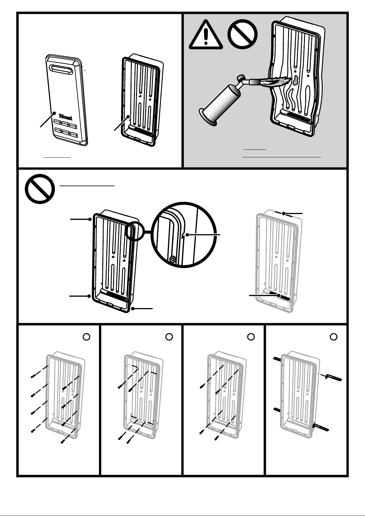
Tak e care to AVOID exposing Smartbox
components to ANY EXCESSIVE HEAT when
welding pipes.
The Smartbox® recess enclosure system is
made up of two (2) components these are the
SBOXI (insert) and SBOXC (cover). Both items
are packaged and purchased separ at el y.
If you DO NOT have a SBOXC (cover) for your
Smatbox contact your supplier.
RA TSD 04-114 Issue 2 29/01/2010
SBOXC
SBOXI
Cover
Clip
Slot
Cover
Clip
Slot
Cover
Clip
Slot
Cover
Clip
Slot
Pipe
Access
Slot
Support
Bracket
Slot
REFER TO THE FOLLOWING INSTALLATION INSTRUCTIONS FOR FULL INSTALLATION DETAILS
DO NOT
Obstr uct the slots provided for the Cover Clips, Support Bracket or P ipe Access
A
Securing the Smartbox
Insert externally
Securing the Smart
Box Insert internally
through the side wall
Securing the Smart
Box Insert internally
through the rear wall
Securing the Smart
Box Insert with the use
of brick ties
Securing Method
B
Securing Method
C
Securing Method
D
Securing Method
Rinnai 1 Smartbox SBOXI/SBOXC/SBOXF
Page 2
Smartbox® RECESS ENCLOSURE COMPONENTS
1
A
B
NOTE
C
E
F
E
D
G
G
IMPORTANT
CAUTION
SBOXI (insert) and SBOXC (cover) packaged and purchased separately.
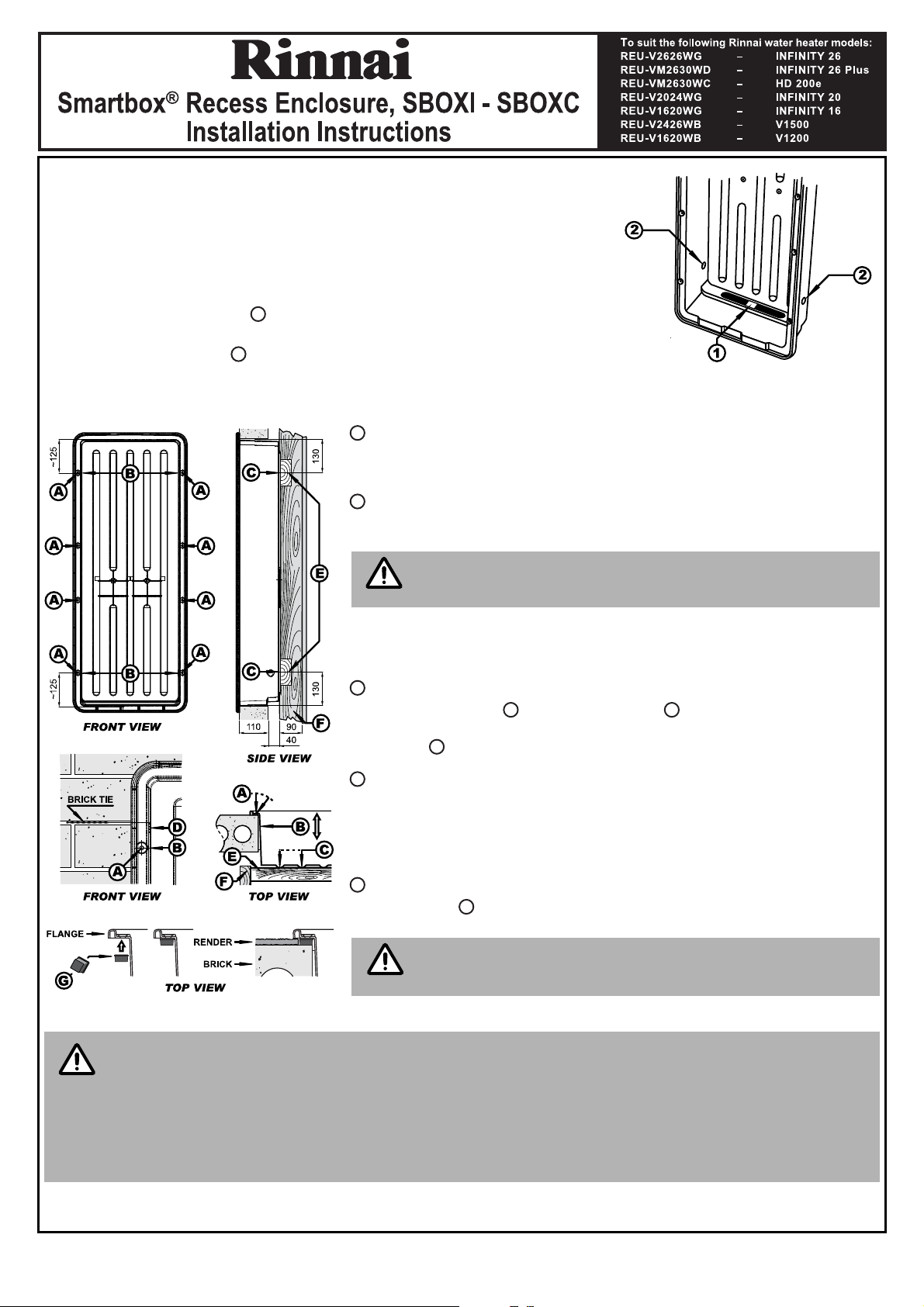
GENERAL PREPERATION
1. Prepare an opening in the wall approximately 1 metre above the ground. The
opening requirements are Height 1030mm, Width 390mm and a minimum Depth
of 160mm (see dimension diagrams page 2). Ensure the location complies with
the requirements of AS 5601 Fig. 5.3.
2. Remove the transport tab from the pipe entry point of the insert.
3. Determine the appropr iate electrical access point and remove either the left or
right the knock out plug located near the bottom of the side walls of the insert.
2
SECURING OPTIONS
The Smartbox insert is designed to be surface mounted and may be secured using one of the fo llowing methods:
Securing the Smartbox Insert externally
Secure to the wall surface via the 8 screw holes provided in the flange of
the insert using suitable fasteners.
Securing the Smartbox Insert internally, through the side wall
Secure the insert into a solid fixture such as brickwork, timber studs etc,
through the side walls using suitable fasteners.
The excess space between t he side walls of the insert and the
solid fixture may require packing to prevent distortion of the
insert.
At least two fasteners should be used through each side wall
approximately 125 mm from the inside top and bottom horizontal faces of
the insert
Securing the Smartbox Insert internally, through the rear wall
Install two noggins between wall studs , these are to be centred at
130 mm from the top and bottom of the opening. Secure the insert into the
noggins through the rear wall using suitable fasteners.
Securing the Smartbox Insert with the use of a brick tie
Secure a brick tie to the side walls of the insert with pop-rivets or screws.
As the brickwork is being laid use the attached brick ties to secure the
insert into the brick courses. Use t wo br ick t i es pe r side , o n e n e ar th e t op
and bottom of the insert.
Installing the Smartbox to rendered surfaces
Use spacers (not provided) to install the Smartbox insert, with sufficient
clearance for rendering.
ASSEMBLY AND APPLIANCE INSTALLATION
THE SMARTBOX COVER AND INSERT ARE CONSTRUCTED FROM DURABLE ABS PLASTIC.
NEVERTHELESS, TAKE CARE WHEN WELDING ANY PLUMBING CONNECTIONS TO ENSURE NO
SMARTBOX PARTS ARE SUBJECTED TO A NAKED FLAME OR EXCESSIVE HEAT.
When the render is applied ensure that the gap provided by
the stand-off sp acers is NOT exceeded as this will prevent the
Smartbox cover from being fitted!
THE SMARTBOX IS NOT SUITABLE FOR INSTALLATION INTO WALLS WHICH ARE REQ UIRED TO BE
‘FIRE RESISTING’ AS DEFINED IN THE BUILDING CODE OF AUSTRALIA (BCA) UNLESS ALTERNATIVE
PROVISIONS ARE MADE TO ACHIEVE THE REQUIRED FIRE RESISTANCE LEVEL (FRL). REFER TO THE
BCA FOR MORE INFORMATION.
4. The gas, cold water inlet and hot water outlet pipes can be brought through the pipe entry point at th e base of the insert.
The pipe entry point is elevated to prevent water ingress. This can be sealed if required.
Rinnai 2 Smartbox SBOXI/SBOXC/SBOXF
Page 3

The Rinnai water heater serial and model numbers on the data plate located on the left hand side of the
IMPORTANT
5
3
8
appliance MUST BE copied to the sticker on the inside of the Smartbox cover. The serial and model
numbers are required for future service work.
5. Remove the two M5 Nyloc nuts from the fixing studs
3 4
of the insert.
6. Insert the upper mounting bracket of the Rinnai water
heater into the bracket slot located at the top of the insert.
7. Push the appliance up until the lower mounting bracket
aligns with the fixing studs and secure in place with the
6
7
4
two M5 Nyloc nuts removed in step 5.
8. Connect the Rinnai water heater in accordance with the
Operation / Installation manual supplied with the water
heater.
9. An approved weatherproof electrical GPO can be fitted on
either side inside the insert in accordance with AS 3000
Wiring Rules.
10.Commission and test the water heater in accordance with the Operation / Installation manual supplied with the water
heater.
11.Attach the warning sticker that is supplied with these instructions to the front cover of the Rinnai water heat er.
12.Install the Smartbox cover by aligning it with the Smartbox insert (the flue spigot hole is to be uppermost) and push
into place ensuring that the 4 locking clips have engaged securely.
DIMENSIONS
Rinnai 3 Smartbox SBOXI/SBOXC/SBOXF
Page 4

Smartbox® SEMI-RECESS FRAME USE
SBOXF
SBOXF
SBOXI
A
A
D
D
D
D
B
B
C
C
NOTE
2
A
IMPORTANT
A
B
C
D
The SBOXF (Frame) is used when a semi-recessed inst allation of
the Smartbox recess enclosure is required. SBOXF reduces the
cavity depth requirements of the SBOXI (Insert) by 60mm. This is
useful where the depth of a wall cavity is insufficient to allow
SBOXI to be fully recessed (for example weatherboard or other
non masonry walls).
The Smartbox Frame (SBOXF) is to be installed at
the same time as the Smartbox Insert (SBOXI) and
Smartbox Cover (SBOXC). These instructions are to
be followed in conjunction with the Installation
Instructions for Insert and Cover supplied with
those items.
GENERAL PREPERATION
1. Prepare an opening in the wall approximately 1 metre above
the ground. The opening requirements are Height 1030mm,
Width 390mm and a minimum Depth of 100mm. Ensure the
location complies with the requirements of AS 5601 Fig. 5.3.
2. When installing the SBOXF (frame) it should be orientated so
that the sealing flange is against the wall surface and the
1
two drainage slots are in the lower most position.
SECURING OPTIONS
The Smartbox Frame and Insert are designed for surface
mounting and may be secured using any of the methods
described below:
Securing SBOXI/SBOXF externally
Use the 8 x 100mm bugle screws that are supplied with the
3
SBOXF (frame) to secure both the SBOXF (frame) and SBOXI
(insert) to the wall surface.
When securing the SBOXI (Insert) and SBOXF
(frame) from the front, use ONLY the 8 screw holes
that are provided. DO NOT attempt to screw or
nail through the sealing flange of the SBOXF (frame)
as this may damage the frame.
Securing SBOXI/SBOXF internally through the side wall
Secure the SBOXI (insert) into a solid fixture such as brickwork,
timber studs etc, through the side walls using suitable
fasteners.
Securing SBOXI/SBOXF internally through the rear wall
Install noggins between wall studs and secure through th e rear
wall of the SBOXI (insert) using suitable fasteners.
Securing SBOXI/SBOXF with the use of brick ties
Secure a brick tie to the side walls of the SBOXI (insert) with
pop-rivets or screws.
Rinnai 4 Smartbox SBOXI/SBOXC/SBOXF, 04-114, Issue 2, 29/01/10
 Loading...