

Rinnai Infinity XR16, REU-V1620WG Infinity HD200, REU-VRM2632WC, Infinity XR20, REU-V2024WG Infinity HD200i Installation Manual
...
Continuous Flow Water
Heaters
Installation Manual
Models are not suitable as a spa or swimming pool heater.
Internal Rinnai continuous flow internal water heaters (‘i’ models) must be installed with an
approved Rinnai flue system.
Appliance must be installed, commissioned and serviced by a licensed tradesperson in
accordance with these instructions and all applicable local rules and regulations.
Your Rinnai continuous flow water heater complies with NZS 5262. A declaration to this effect
can be found on the Energy Safety web site; www.energysafety.govt.nz..
To suit models:
Rinnai Infinity XR16 REU-V1620WG Rinnai Infinity HD200 REU-VRM2632WC
Rinnai Infinity XR20 REU-V2024WG Rinnai Infinity HD200i/HD200ia REU-VR2632FFUG
Rinnai Infinity XR24 REU-V2426WG Rinnai Infinity HD250/HD250a REU-VR3237WG
Rinnai Infinity XR26 REU-V2630WG Rinnai Efficiency 24 REU-K2430WG
Rinnai Infinity XR26a REU-V2630WGT Rinnai Efficiency HD250 REU-KM3237WD
Rinnai Efficiency HD250i REU-KM3237FFUD
i = internal a = aggressive water units HD = Heavy Duty

Rinnai New Zealand Continuous Flow Water Heater Installation Manual:
01-09
2
Contents
WARNING
Improper installation, adjustment, alteration, service or maintenance
can cause property damage, personal injury or loss of life.
For assistance or additional information contact Rinnai on
0800 TO RINNAI (0800 86 746 624).
Before Installation 3
Applicable Models 3
Appliance Location 4
General Installation Information 6
Connections and Fittings 8
Dimensions - XR and HD Range 9
Dimensions - Efficiency Range 10
Condensate Drain - Efficiency Models Only 12
Controllers - General 14
Controllers - Universal Installation 16
Controllers - Kitchen Deluxe Installation 17
Controllers - Bathroom Deluxe Installation 18
Controllers - Communication Cables 19
Commissioning 21
Recommended Solar System Layout 22
Dip Switch Settings 23
Rinnai New Zealand Continuous Flow Water Heater Installation Manual:
01-09
3
Before Installation
Unpack appliance and flue components (if applicable) and check for damage.
DO NOT install any damaged items.
Check all components have been supplied and that you have the correct gas type.
Read these instructions to get an overview of the steps required before starting the
installation. Failure to follow these instructions could cause a malfunction of the
appliance. This could result in serious injury and property damage.
For Rinnai continuous flow water heaters used in solar installations, refer
‘Recommended Solar System Layout’.
The Rinnai Efficiency Heavy Duty (HD) models are 32 kg. Please use care when
lifting and seek assistance if required.
This appliance must be installed in accordance with:
Current AS/NZS3000, AS/NZS2500, NZS 5261 and G12/AS1
Rinnai installation instructions
Local regulations and municipal building codes
Installation, service and removal must be by an authorised person only.
•
•
•
32 kg
Heavy
These installation instructions apply to the following Rinnai continuous flow water heaters.
Rinnai Infinity XR16 External REU-V1620WG
Rinnai Infinity XR20 External REU-V2024WG
Rinnai Infinity XR24 External REU-V2426WG
Rinnai Infinity XR26 External REU-V2630WG
Rinnai Infinity XR26a External REU-V2630WGT
Rinnai Infinity HD200 External REU-VRM2632WC
Rinnai Infinity HD200i/HD200ia Internal REU-VR2632FFUG
Rinnai Infinity HD250/HD250a External REU-VR3237WG
Rinnai Efficiency 24 External REU-K2430WG
Rinnai Efficiency HD250 External REU-KM3237WD
Rinnai Efficiency HD250i Internal REU-KM3237FFUD
i = internal
a = aggressive water units
HD = Heavy Duty
Applicable Models
Rinnai New Zealand Continuous Flow Water Heater Installation Manual:
01-09
4
Appliance Location
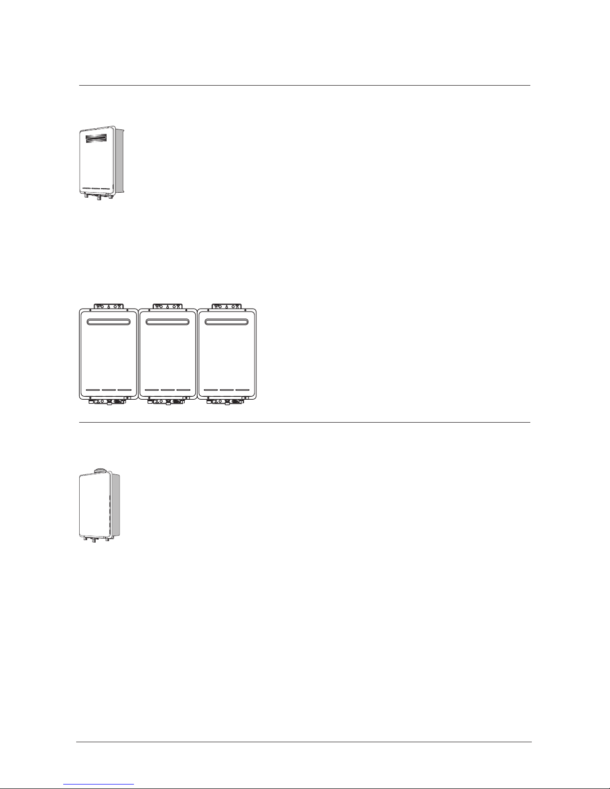
External models
External models are designed for outdoor installations only. They must be located
in an above ground open-air situation with natural ventilation, without stagnant
areas, and where gas leakage and products of combustion are rapidly dispersed
by wind and natural convection.
They must be mounted on a vertical structure with the water and gas connections
on the underside pointing downwards. For appliances installed on elevated
structures or under floors specific requirements apply. Refer to NZS 5261 for
details.
Location of the appliance flue terminal must be in accordance with NZS 5261 section 2.6.11,
2.6.12 and 2.6.13.
When multiple units of the same model are installed on the same vertical face, with the flue
terminals at the same height, they can be installed next to each other (as shown).
Internal models
Internal models are designed for indoor installations only. They may be installed
in an enclosure if the requirements of NZS 5261 are satisfied. An enclosure is
defined as a compartment, enclosed area or partitioned off space primarily used
for the installation of the appliance. If installed in an enclosure either internally or
externally, the location should be ventilated to allow gas to dissipate.
They must be mounted on a vertical structure with the water and gas connections
on the underside pointing downwards. For appliances installed in roof spaces or elevated
structures, specific requirements apply. Refer to NZS 5261 section 1.6 for details.
This appliance MUST be used with an approved Rinnai flueing system. The use of a non-Rinnai
flueing system may result in a dangerous situation and violates regulations.
This appliance must be located so that the flue terminal exits the building at a suitable point,
refer ‘Minimum Clearances Required for Flue Terminals’, NZS 5261-2003.

Rinnai New Zealand Continuous Flow Water Heater Installation Manual:
01-09
5
Appliance Location
All models
This appliance must be placed as close as possible to the most frequently used hot water outlet
or outlets to minimise the delay for hot water delivery.
For installations where the distance between the water heater and the outlets is considerable,
a flow and return system can be used to minimise the waiting time for hot water delivery.
Alternatively, multiple appliances can be strategically placed to serve different outlets. Contact
Rinnai for further information.
An AC230 V, 10 Amp, earthed power point must be provided adjacent to the appliance. For
outdoor installations, this power point must be weatherproof. It must be clear of the gas and
water connections to the appliance and also the flue exhaust and water pressure relief valve.
The power cord of the appliance is 1.5 m long.
All appliances must be installed to ensure access can be gained without hazard or undue
difficulty for inspection, repair, renewal or operational purposes. Sufficient clearances shall
allow access to and removal of all serviceable components.
Appliances should not be mounted higher than 3.5 m above the ground or floor level unless
the customer can arrange permanent and safe access or can provide another means of access
such as scissor or boom lifts.
Rinnai New Zealand Continuous Flow Water Heater Installation Manual:
01-09
6
General Installation Information
Catch pan
It is important a suitably drained catch pan is fitted (especially for internal units) where
damage could be caused by discharge from the water heater. Provision must be made for safe
disposal of any leaking water to an external location.
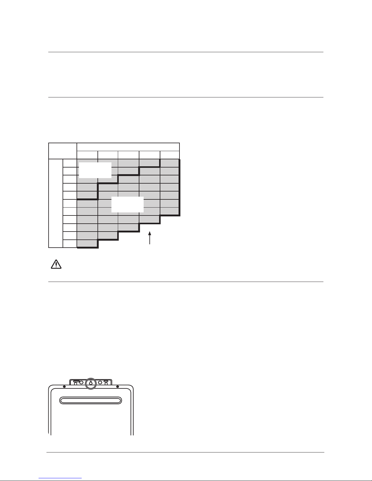
Flued water heaters (internal units)
The chart below highlights the maximum flue length and number of bends. It also shows the
difference between a short and long flue—this is important if changing settings (dip switches).
Number of 90 Degree Bends
0 1 2 3 4
Flue Length (m)
1
2
3
4
5
6
7
9
11
13
15
Short flue
setting
Long flue
setting
Maximum flue length
For flues over 2 m there is a dip switch change required. Refer Commissioning Checklist
supplied with this appliance.
IMPORTANT
Mounting the appliance
Refer ‘Connections and Fittings’ for individual appliance weights. The wall or structure on which
these units are to be mounted must be capable of supporting these weights and the associated
pipe work.
Ensure suitable fixing screws or bolts are used to secure the units to the walls, in accordance
with NZS 5261 (section 5.0). Wooden plugs shall not be used.
The top bracket has a keyhole slot (circled below) so the appliance can be positioned by
hanging it on one screw while the other screws are secured.
Rinnai New Zealand Continuous Flow Water Heater Installation Manual:
01-09
7
General Installation Information
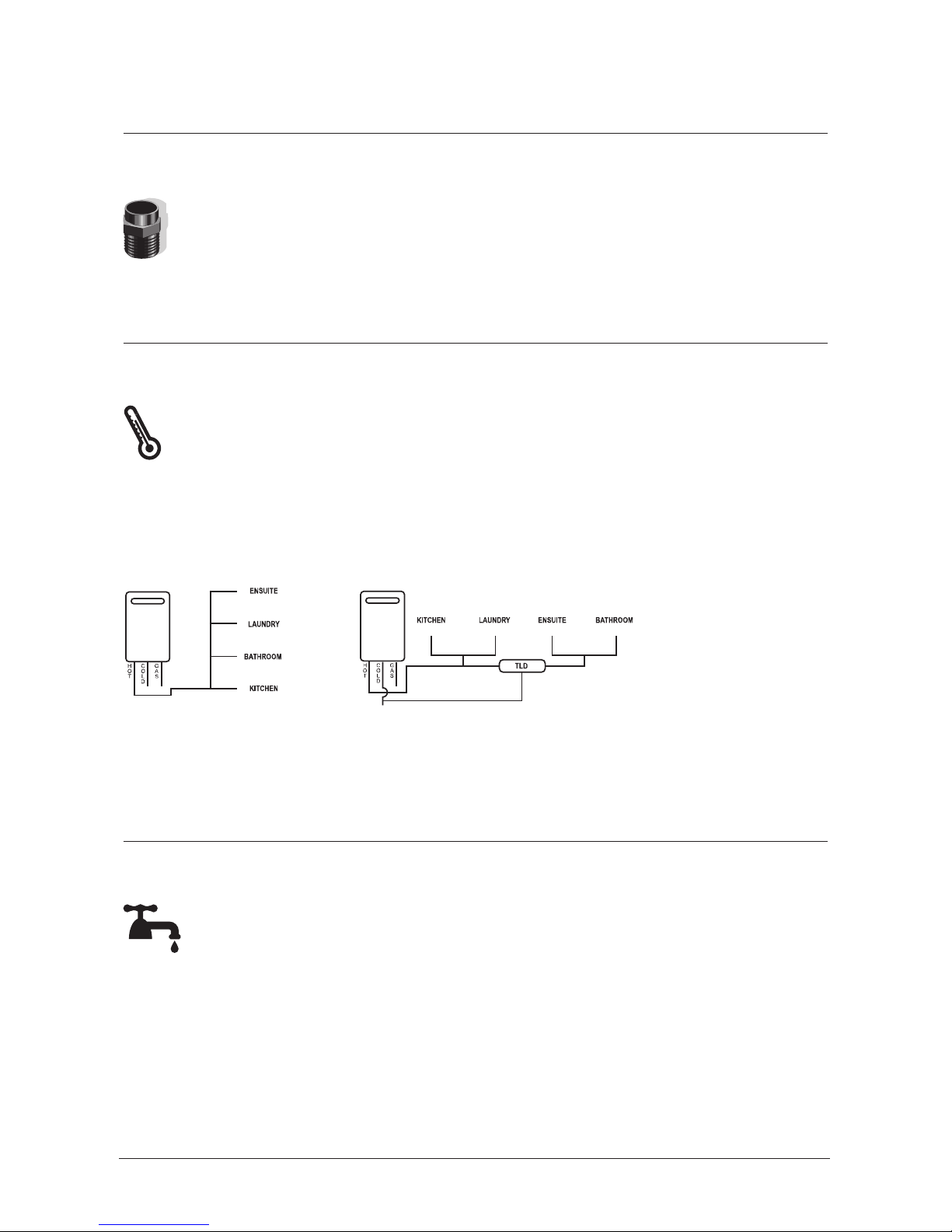
Water delivery temperature
Local regulations and/or requirements of AS/NZS3500.4 must be considered regarding
the temperature limitations of hot water supplied to areas used primarily for personal
hygiene. The temperature of these areas may be limited to 55 °C or less.
If the appliance is to deliver water primarily for the purposes of personal hygiene in an
early childhood centre, school, nursing home or similar facility as defined in AS/NZ3500.4 a
Temperature Limiting Device (TLD), such as a Tempering Valve may be required (even if the
appliance is set to 55 °C or less). For these types of applications contact Rinnai.
Diagram 1 - 55 °C Appliance
55 °C
Diagram 2 - Not a 55 °C Appliance
(TLD = Temperature Limiting Device)
> 55 °C > 55 °C < 55 °C < 55 °C
Requirements for Rinnai Continuous Flow Units Installed Without Controllers
Pipe sizing
Refer ‘Connections and Fittings’ for appliance gas consumption. If the gas pipe sizing is
insufficient the customer will not get the full performance benefit. Gas pipe sizing must
consider the gas input to this appliance as well as all the other gas appliances in the
premises. The gas meter and regulator must be specified for this gas rate. An approved
sizing chart such as the one in NZS 5261 should be used.
Water pipe sizing and layout should be performed in accordance with AS/NZS3500. All hot
water pipe work should be insulated to optimise performance and energy efficiency.
When the continuous flow unit is set to deliver water at a temperature higher than 55 °C, it will
be necessary to fit a Temperature Limiting Device for delivery to areas used for the purposes of
personal hygiene. Refer Department of Building and Housing G12.
Water supply
Refer ‘Connections and Fittings’ for applicable water pressures. Approved pressure
limiting valves may be required if the stated maximum rated water supply pressures
are exceeded. To achieve the rated flow, the stated minimum water supply
pressures must be supplied. The water heaters will operate at lower pressures but
will not achieve the rated flow.
Water chemistry and impurity limits are stated in our detailed warranty statement. Most
metropolitan water supplies fall within these requirements. If you are unsure about the quality
of the water, please contact Rinnai and we will provide you with the details of an authorised
agency who are able to test your water for compliance to Rinnai standards. If sludge or foreign
matter is present in the water supply, a suitable filter or strainer should be incorporated in the
water supply to the water heater.

Rinnai New Zealand Continuous Flow Water Heater Installation Manual:
01-09
8
Connections and Fittings
Models Gas Consumption
MJ/h
Water
Supply kPa
Weight
kg
Fittings Condensate
Min. Max. Hot Cold Gas
XR16 Ext
REU-V1620WG
125 120 1000 15
R½
(15 mm)R½(15 mm)R¾(20 mm)
XR20 Ext
REU-V2024WG
160 160 1000 15
R¾
(20 mm)R¾(20 mm)R¾(20 mm)
XR24 Ext
REU-V2426WG
188 180 1000 15
R¾
(20 mm)R¾(20 mm)R¾(20 mm)
XR26 Ext
REU-V2630WG
199 130 1000 17
R¾
(20 mm)R¾(20 mm)R¾(20 mm)
XR26a Ext
REU-V2630WGT
199 130 1000 17
R¾
(20 mm)R¾(20 mm)R¾(20 mm)
HD200 Ext
REU-VRM2632WC
199 140 1000 21
R¾
(20 mm)R¾(20 mm)R¾(20 mm)
HD200i/HD200ia Int
REU-VR2632FFUG
195 140 1000 21
R¾
(20 mm)R¾(20 mm)R¾(20 mm)
HD250/HD250a Ext
REU-VR3237WG
250 200 1000 29
R¾
(20 mm)R¾(20 mm)R¾(20 mm)
Efficiency 24 Ext
REU-K2430WG
162 240 1000 27
R¾
(20 mm)R¾(20 mm)R¾(20 mm)
R½
(15 mm)
Efficiency HD250 Ext
REU-KM3237WD
211 240 1000 32
R¾
(20 mm)R¾(20 mm)R¾(20 mm)
R½
(15 mm)
Efficiency HD250i Int
REU-KM3237FFUD
211 240 1000 32
R¾
(20 mm)R¾(20 mm)R¾(20 mm)
R½
(15 mm)
Service connection points
These dimensions are NOT an indication of the pipe sizes required.
An approved full flow isolation valve and disconnection union MUST be fitted to the cold water
inlet. A non-return valve is not required unless required by local regulations.
Isolation valves must be fitted so the appliance can be removed.
Purge gas and cold water supply lines to remove air and swarf before final connection of the
appliance. Swarf in the gas or water supplies may cause damage.
Rinnai New Zealand Continuous Flow Water Heater Installation Manual:
01-09
9
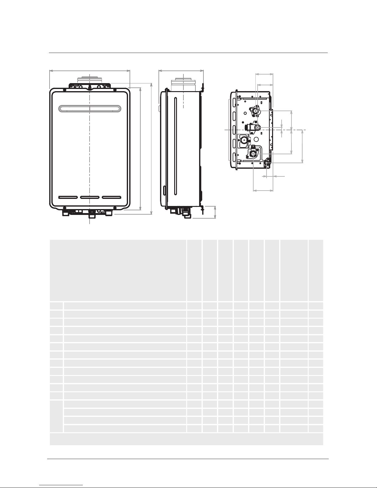
Dimensions - XR and HD Range
B
DC
M
A
E
F
J
L
H
G
I
K
Dimension (mm)
XR16 Ext
(REU-V1620WG)
XR20 Ext
(REU-V2020WG)
XR24 Ext
(REU-V2426WG)
XR26 Ext
(REU-V2630WG)
XR26a Ext
(REU-V2630WGT)
HD200 Ext
(REU-VRM2632WC)
HD200i/HD200ia Int
(REU-VR2632FFUG)
HD250/HD250a Ext
(REU-VR3237WG)
A Width 350 350 350 350 350 350 350 470
B Depth 194 194 194 194 194 250 235~275 244
C Height - Unit 530 530 530 530 530 600 600 600
D Height - Including Brackets 571 571 571 571 571 636 641 644
E Hot Water Outlet (from wall) 87 87 87 87 87 95 91~131 115
F Hot Water Outlet (from centre) 105 105 105 105 105 10 110 61
G Cold Water Inlet (from wall) 68 68 68 68 68 74 70~110 99
H Cold Water Inlet (from centre) 10 10 10 10 10 27* 27* 52
I Gas Connection (from wall) 77 77 77 77 77 103 99~139 61
J Gas Connection (from centre) 83 83 83 83 83 89 89 110
K Condensate Outlet (from wall) • • • • • • • •
L Condensate Outlet (from centre) • • • • • • • •
M Gas: Length Gas Connection (from base) 40 40 40 40 40 41 41 41
Cold: Length of Cold Water Inlet (from base) 50 50 50 50 50 51 51 51
Hot: Length of Hot Water Outlet (from base) 42 42 42 42 42 42 42 42
Condensate Connection Length (from base) • • • • • • • •
* this measurement is to the left of the centre line
 Loading...