

Rinnai REU-V2632FFUG, REU-VM2632FFUC Service Manual

SERVICE MANUAL
T
o Suit Models:
Does NOT Suit Other Models
REU-V2632FFUG
REU-VM2632FFUC
DRDAFT

All Rinnai products are certified by the
Distributed and serviced in Australia under a Quality
System certified as complying with ISO 9001 by
SAI Global
SAI Global
Australian Gas Association as compliant
to relevant Australian Standards.
Rinnai Australia Head Office is certified
as complying with ISO 9001 by SAI
Global.
Rinnai New Zealand has been certified to
ISO 9001 Quality Assurance by Telarc.
All Rinnai products are Certified to
WaterMark by SAI Global. WaterMark
certification is awarded to products and
fittings complying with safety and water
contamination standards.

Glossary of Terms and Symbols
dB(A) - sound pressure level in decibels, “A” range
DC - direct current
AC - alternating current
WFCD - water flow control device
FB - feedback information
FF - feed forward information
Hz - Hertz
IC - integrated circuit
kcal/h - kilocalorie per hour
kPa - kilopascals
LED - light emitting diode
L/min - Litres per minute
mA - milliamps
MJ/h - megajoule per hour
mm - millimetres
O - millimetres of water (gauge pressure)
mmH
2
OHS - overheat switch
PCB - printed circuit board
CPU - central processing unit
POT - potentiometer
rpm - revolutions per minute
SV - solenoid valve
ø - diameter
o
C - temperature rise above ambient
POV - modulating valve
TE - thermal efficiency
TH - thermistor
T
IN
T
OUT
Infinity REU-V2632FFUG / HD200i REU-VM2632FFUC - iii - Issue 1 - 16/12/09 ©Rinnai
- temperature of incoming water
- temperature of outgoing water

© Copyright Rinnai Australia Pty Ltd ABN 74 005 138 769
WARNING
WARNING
All rights reserved
Produced by Engineering & Technical Group
No portion or part of this manual may be copied without prior
permission from Rinnai Australia.
Rinnai Australia reserves the right to make modifications and change
specifications without notice.
W A R N I N G
Failure to comply with these instructions may result in serious personal
injury or damage to the appliance.
• All wiring inside this appliance may be at 240 Volts potential.
• All service work must be carried out by an authorised person.
This manual has been published by Rinnai Australia Engineering &
Technical Group.
We welcome users of this manual to provide feedback and suggestions
for improvement purposes.

Table of Contents
Glossary of Terms and Symbols ......................... ....................................................... iii
1. Specifications ............................................................................................................. 1
2. Water Flow Rates and Pressures ................................................................................ 3
3. Dimensions ................................................................................................................ 4
4. Water Controllers ....................................................................................................... 5
5. Smartstart ................................................................................................................... 7
6. Operational Flow Chart ............................................................................................. 8
7. Cutaway Diagram .................................................................................................... 10
8. Operation Principles ................................................................................................ 11
9. Main Components .................................................................................................... 12
10. Time Charts ............................................................................................................ 13
11. Wiring Diagram ..................................................................................................... 14
12. Component Circuit Value Table ............................................................................ 15
13. Dip Switch Settings ............................................................................................... 16
14. Fault Finding .......................................................................................................... 17
15. Component and Circuit Checks ............................................................................. 19
16. Maintenance Monitor / Error History .................................................................... 24
17. Gas Pressure Setting Procedure ............................................................................. 27
18. Gas Conversion Procedure ..................................................................................... 27
19. Dismantling for Service ......................................................................................... 29
20. Parts List ................................................................................................................ 37
21. Exploded Diagram ................................................................................................. 41
SERVICE CONTACT POINTS .................................. ............................................. 45
Infinity REU-V2632FFUG / HD200i REU-VM2632FFUC - v - Issue 1 - 16/12/09 ©Rinnai

1. Specifications
Rinnai model number
Type of appliance Temperature controlled continuous flow gas hot water system
Combustion system Room sealed, fan forced combustion
Installation Internal
Dimensions Width
Weight 21 kilograms
Gas consumption (Min. / Max.) Natural gas:
Connections Gas connection
Ignition system Direct electronic ignition
Electrical consumption Normal
Delivery Temperatures 40°C, 42°C, 50°C, 55°C, 65°C, 75°C & 85°C
Water flow control Water flow sensor, electronic water flow control device and electronic
Maximum hot water capacity, raised
@ 25°C
Water pressure required to achieve
maximum water flow
Minimum water flow for operation 2.4 L/min
Power supply Appliance - AC 240 Volts 50 Hz
Water controllers (optional)
Water Controller Cable
(Supplied with controller) Non-polarized two core cable.
REU-V2632FFU
REU-VM2632FFUC
Height
Depth
Propane gas:
Cold water connection
Hot water connection
Standby
(set by combination of dip switches on PCB)
By-Pass flow control device.
26 L/min
140 kPa
Water controller - DC 12 Volts
1. Up to 4 controllers can be fitted.
See below for the combination limitation of water controllers
2. Wireless controllers can be fitted in the same manner of
MC-91Q-2A
Kitchen control MC-100V-1A or MC-91Q-2A
Bathroom control BC-100V-1A or MC-91Q-2A
Second bathroom control BC-100V-1A or MC-91Q-2A
Third bathroom control MC-91Q-2A
G
350 mm
600 mm
259 mm
16~195 MJ/h
16~195 MJ/h
R3/4 (20A)
R3/4 (20A)
R 3/4 (20A)
45 W
2 W (with 1 water controller)
Infinity REU-V2632FFUG / HD200i REU-VM2632FFUC - 1 - Issue 1 - 16/12/09 ©Rinnai

Sensors and Safety Functions
• Hot Water Delivery Thermistor: Measures hot water temperature at the appliance outlet connec-
tion (i.e. the ‘mixed’ temperature).
• Flame Rod: Monitors combustion characteristics inside the combustion chamber. If the flame fails,
gas supply is stopped.
• Overheat Switch: Situated on the heat exch anger, ga s supply is stopped when wate r temperature
reaches 97ºC for a number of seconds.
• Fusible Link: Situated on the heat exchanger, electrical power supply is stopped if the temperature
exceeds 129ºC.
• Water Pressure Relief Valve: Safeguards the water circuit against excessive inlet pressure. Opens
at 2060 kPa, closes at 1470 kPa.
• Electrical Fuse: (3A glass fuse) prevents against over-current.
Surge Protector: prevents against over-current.
• Boil Dry Prevention: If water flow sensor detects no flow, gas supply is stopped.
• Combustion Fan Speed Sensor: In case of combustion fan defect (no rotation of fan) gas supply is
stopped.
• Temperature Cutout: If the delivered hot water temperature rises above the required delivery
temperature for a number of seconds, the gas supply is stopped.
Combustion Specifications
See dataplate on appliance.
Infinity REU-V2632FFUG / HD200i REU-VM2632FFUC - 2 - Issue 1 - 16/12/09 ©Rinnai

2. Water Flow Rates and Pressures
Water Flow vs Pressure Graphs
Inlet pressure (kPa)
Outlet flow (litres/minute)
))8
REU-V2632WC & FFU
P(kPa) 0 20 30 40 50 60 70 80 100 120 140 150 200 300
Q(L/min)@Tset37 0 11.3 14.8 16.9 19 20.8 22.8 24.2 27 29.8 32 32 32 32
Q(L/min)@Tset60 0 6.4 10.4 13 15 16.5 18 19.4 21 22.5 23.5 23.8 24
Water flow rate and pressure characteristics as shown below.
Infinity REU-V2632FFUG / HD200i REU-VM2632FFUC - 3 - Issue 1 - 16/12/09 ©Rinnai
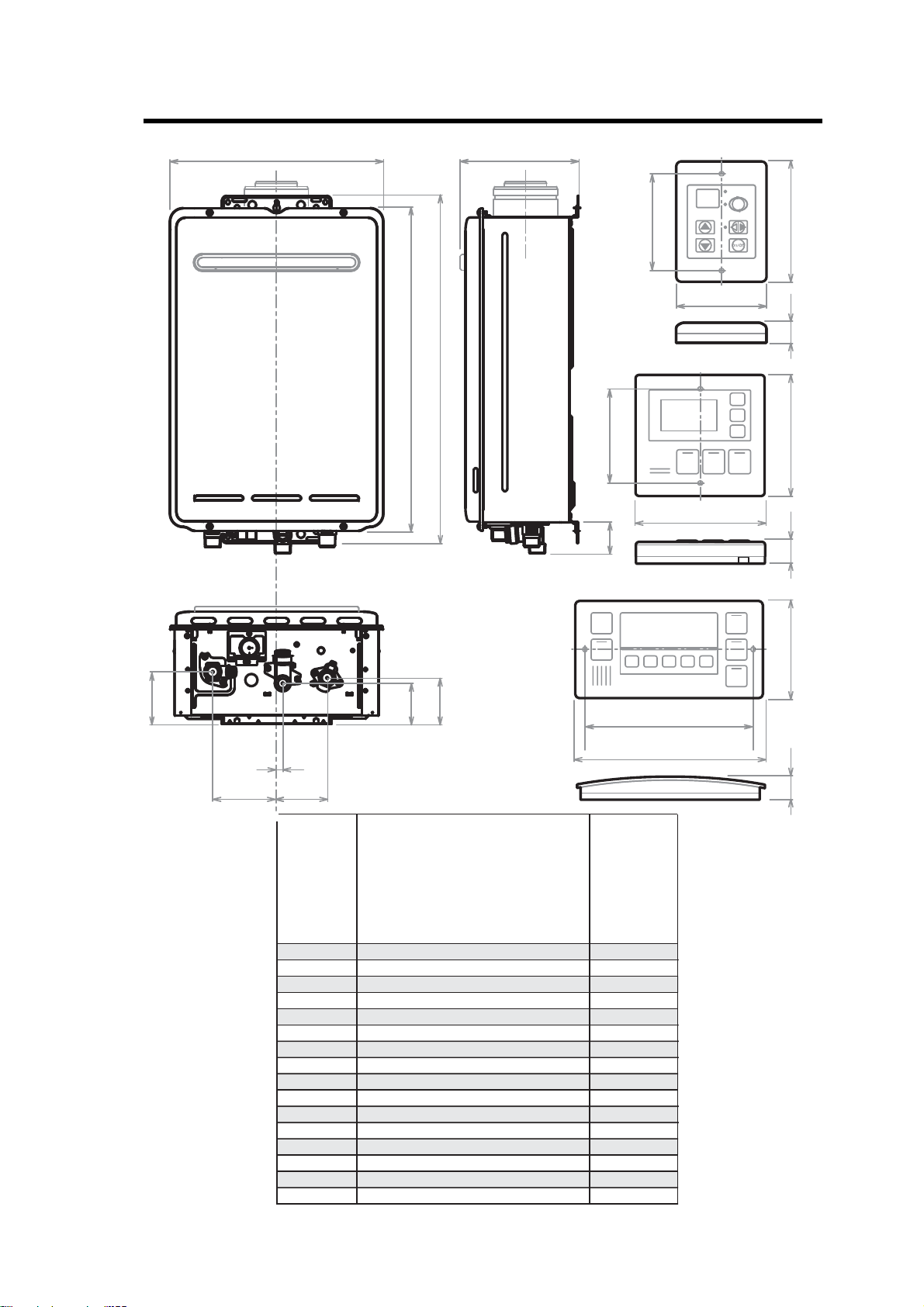
3. Dimensions
Dimensions Description
A Width
B Depth
C Height - Unit
D Height - Including Brackets
E Hot Water outlet (from wall)
F Hot Water outlet (from centre)
G Cold Water inlet (from wall)
H Cold Water inlet (from centre)
I Gas Connection (from wall)
J Gas Connection (from centre)
Gas: Length (from base)
Cold: Length (from base)
Hot: Length (from base)
Gas: Fitting Diameter
Cold: Fitting Diameter
Hot: Fitting Diameter
K
L
BC-100V
MC-100V
MC-91Q
90
120
83
120104
128
202
202022
181
B
D
C
K
A
E
F
J
H
I
G
L
FITTING
DIAMETER
* Please note that this measurement is to the left of the centre line.
83
REU-V2632FFUG
REU-VM2632FFUC
350
234.5 ~ 274.5
600
641
91 ~ 131
110
70 ~ 110
27 *
99 ~139
89
41
51
42
20
20
20
Infinity REU-V2632FFUG / HD200i REU-VM2632FFUC - 4 - Issue 1 - 16/12/09 ©Rinnai

4. Water Controllers
NOTE
water controllers must be installed in accordance with the relevant operation/installation instructions supplied with the
water heater or controllers.
Care should be taken to ensure power supply to the Infinity is isolated when connecting /
disconnecting controller wiring or transponder on wireless controllers. Failure to isolate
power supply may result in damage to the appliance PCB.
Care should be taken when closing the Ezi-connect access panel, to ensure internal wiring
for controllers is not shortened or crushed.
Troubleshooting
Water Controller not showing display - (Wired Water Controllers)
• Check that the correct number and combination of co ntrollers have b een installed for the specific model
Infinity. Refer to controller compatibility table below.
• Check water controller is turned ON.
• Check there is 12VDC power supply available to the controller from the Ezi-connect terminals.
• If there is 12VDC available from the Ezi Connect but no controller display, check wiring between Ezi-connect
and controller is sound.
• If there is no power from the Ezi-connect terminals, but the hot water functions correctly, replace PCB.
Error Code 12 as soon as hot water tap is turned ON.
• Check 12VDC internal wiring to Ezi-connect terminal is not crushed or shorted.
• Rectify wiring and re-close Ezi-connect cover carefully.
Water Controller not showing display - (Wireless Water Controllers)
• Ensure transceiver module is mounted in the correct location, as per wireless controller installation instructions.
• Ensure 2 x AA batteries are in good working order and installed with the correct polarity within the wireless
controller. (Battery polarity details on rear of wireless controller)
• Ensure distance between wireless controller and transceiver does not exceed 50 metres.
• Ensure channel has been allocated to each wireless controller.
• Ensure w ireless co ntroller has been pro grammed to the transceiver correctly , as per wireless controller
installation instructions.
Water Controller Compatibility Table
A
l
l
Wireless Only
Installation
Wired &
Wireless
Installations
Infinity REU-V2632FFUG / HD200i REU-VM2632FFUC - 5 - Issue 1 - 16/12/09 ©Rinnai
A maximum of 4 wireless water controllers can be fitted with the following limitation:
Only ONE
A maximum of 4 water controllers can be fi tted. Any combination of delux e, universal and
wireless controllers can be used with the following limitation:
Only ONE
programmed as a master controller) or a MC-502RC/MC-503RC water controller.
Up to TWO
The FOURTH
or a MC91Q.
MC-502RC / MC-503RC can be set as the Master Controller.
master controller can be installed. This can be a MC-100V, a MC-91Q (when
BC-100V water controllers can be installed.
water controllers in any installation MUST BE a MC-502RC / MC-503RC
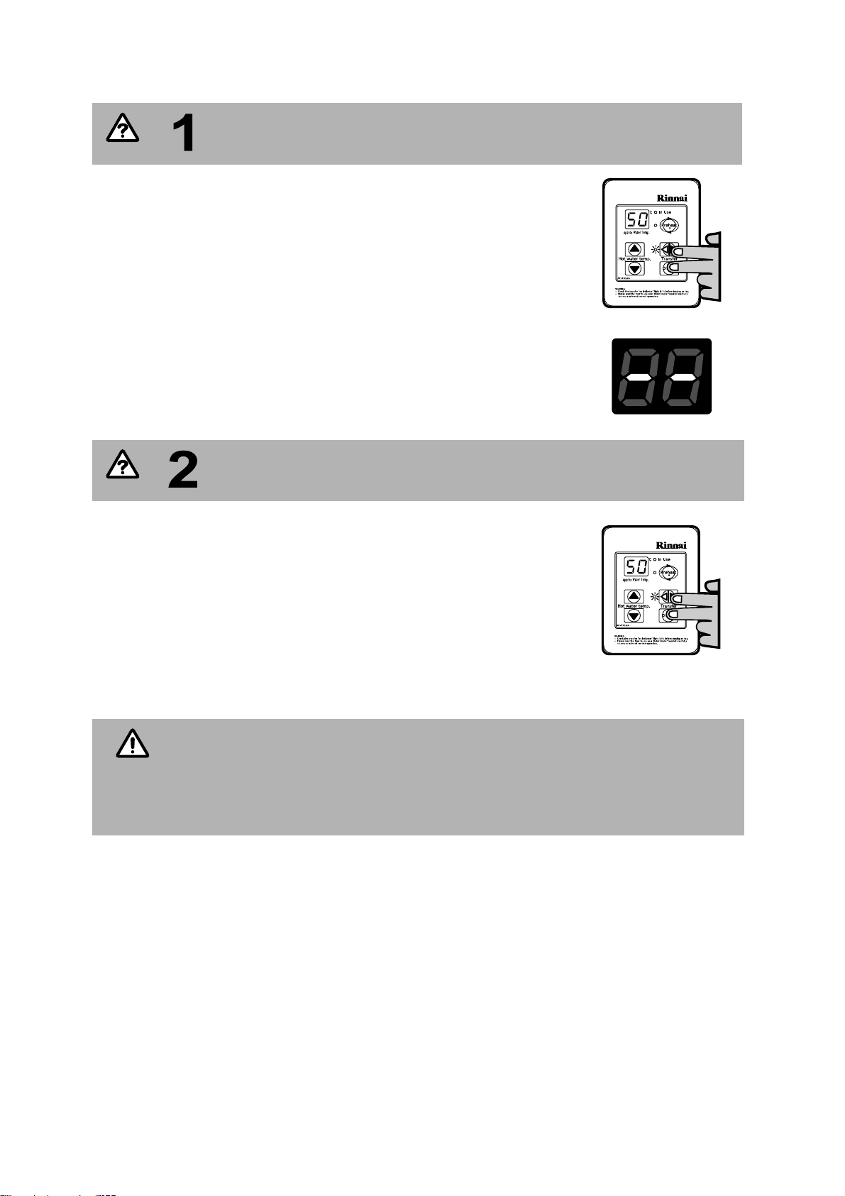
PROGRAMMING FOR THE ‘UNIVERSAL’ WATER CONTROLLER (MC-91Q)
QUESTION
QUESTION
NOTE
Are there four water controllers connected?
IF NO: (You have three water controllers or fewer), go to Question 2.
IF YES: You will need to activate the fourth water controller as follows:
STEP 1: For the water co ntroller in the KITCHEN ONLY, press and h old the
‘Transfer’ and ‘On/Off’ b uttons si multaneously (see Fig. 5) unt il a
‘beep’ is heard (approximately 5 seconds).
STEP 2: Check th at th e di splay o n A LL FOU R water con trollers is l it an d
displaying a tem perature wh en ‘swi tched on ’. If any ONE of the
controller displays two dashes (see Fig. 6) repeat STEP 1.
This completes the activation proced ure for the fourth co ntroller, you
may ignore Question 2.
Is the water heater marked to state it delivers water not
exceeding 50°C?
IF YES: No further action required.
IF NO: You will need to program the kitchen controller to enable selection of
temperatures higher than 50°C.
STEP 1: For the controller in the KITCHEN ONLY, press and hold the
‘Transfer’ and ‘On/Off’ buttons simultaneously (Fig. 7) until a ‘beep’ is
heard (approximately 5 seconds).
STEP 2: When the controller fitted in the KITCHEN is switched On, it should be
possible to select temperatures higher than 50°C. If not, repeat STEP 1.
Fig. 5
Fig. 6
Fig. 7
If the water controller in the kitchen is replaced, repeat STEP 1 above for the replacement
controller.
If the water controller in the kitchen is swapped with another controller (for example, the
controller fitted in a bathroom), repeat STEP 1 for the controller moved from the kitchen
to the bathroom. Then perform STEP 1 for the controller moved fro m bathroom to the
kitchen.
Infinity REU-V2632FFUG / HD200i REU-VM2632FFUC - 6 - Issue 1 - 16/12/09 ©Rinnai
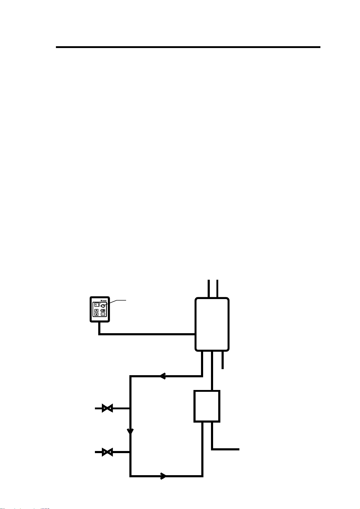
5. Smartstart
H
O
T
C
O
L
D
G
A
S
Cold Inlet Mains
Smartstart®
Module
Rinnai Continuous
Flow Water Heater
Hot Water
Outle t
Hot Water
Outle t
HeatingLoopFlow
Heating Loop Return
Oneor more
MC-91Q
Controllers
Preheat Button
At least one temperature controller model MC-91Q must be used in conjunction with the water heater
and the Smartstart® system. Alt ernatively, if water c ontrollers cannot be used a manual a ctivation
switch must be used. Water Controllers cannot be used with the REU-V2426WS model.
At least one water controller model MC-91Q must be used in conjunction with the water heater and the
Smartstart® system. Alternatively, if water contro llers cannot be used a manual activation switch is
available. Refer to the installation manual for the Smartstart® system.
The installation of th e water heat er and wat er controllers must be performed in acc ordance with the
operating/installation instructions supplied with the water heater.
The Smartstart® system is designed for domestic installations. However, it may be suitable for certain
non domestic installations.
Principle of operation
The "Smartstart®" system heats the water in the pipework water connected between the water heater
and the hot water outlets before any outlets are opened using the 'flow and return' pipework principle.
This results in water savings and reduced waiting time for heated water delivery from the outlet when
opened.
Traditional 'flow and return' systems usually keep the water in the pipework heated continuously. The
Smartstart® system however, only heats the water before the outlet is opened. This results in significant
energy savings because water is not heated unnecessarily whilst retaining the benefits of traditional flow
and return systems.
A schematic of the Smartstart® system installed in conjunction with a Rinnai continuous flow water
heater and water controller as shown below.
If problems are experienced with Smartstart® operation refer to the Smartstart® Service Manual.
Infinity REU-V2632FFUG / HD200i REU-VM2632FFUC - 7 - Issue 1 - 16/12/09 ©Rinnai
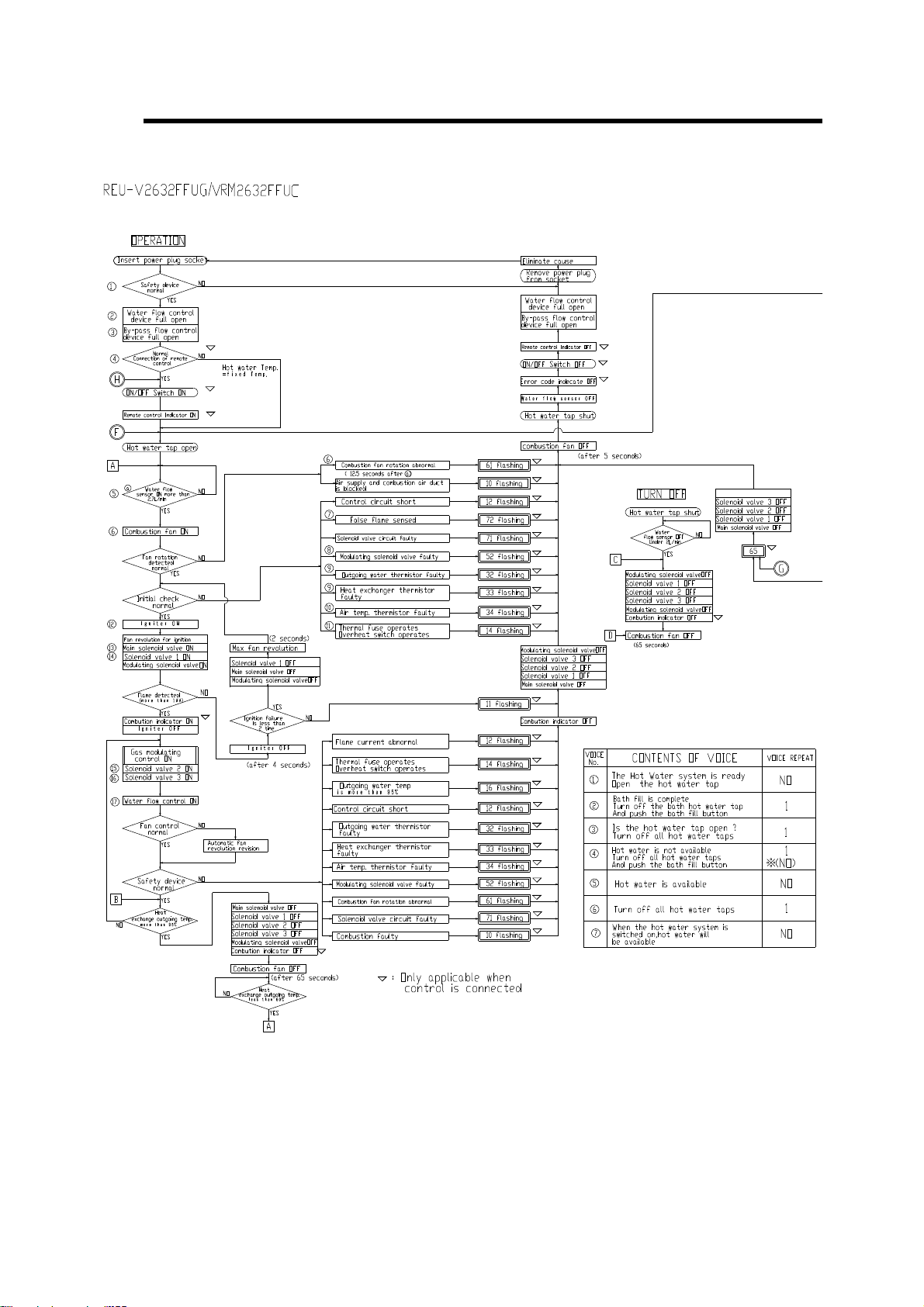
6. Operational Flow Chart
Infinity REU-V2632FFUG / HD200i REU-VM2632FFUC - 8 - Issue 1 - 16/12/09 ©Rinnai
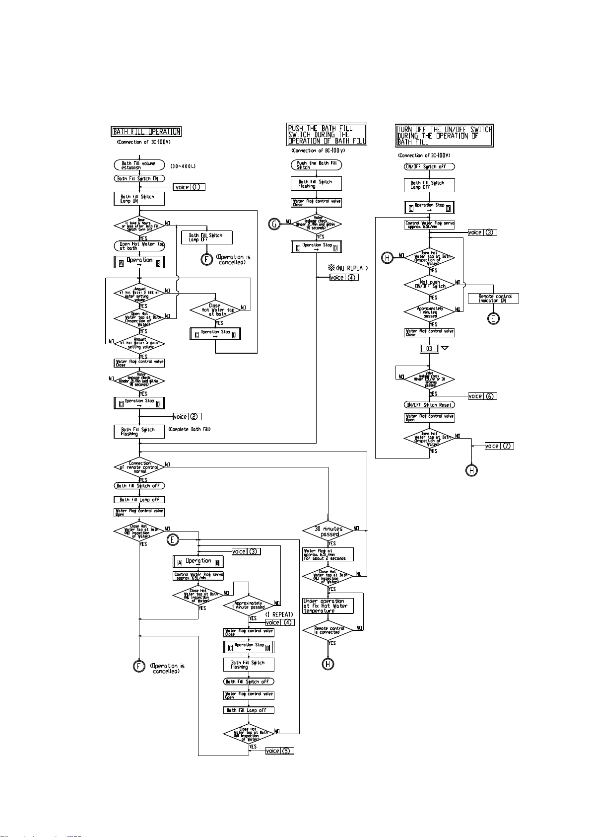
Operational Flow Chart - Continued
Infinity REU-V2632FFUG / HD200i REU-VM2632FFUC - 9 - Issue 1 - 16/12/09 ©Rinnai
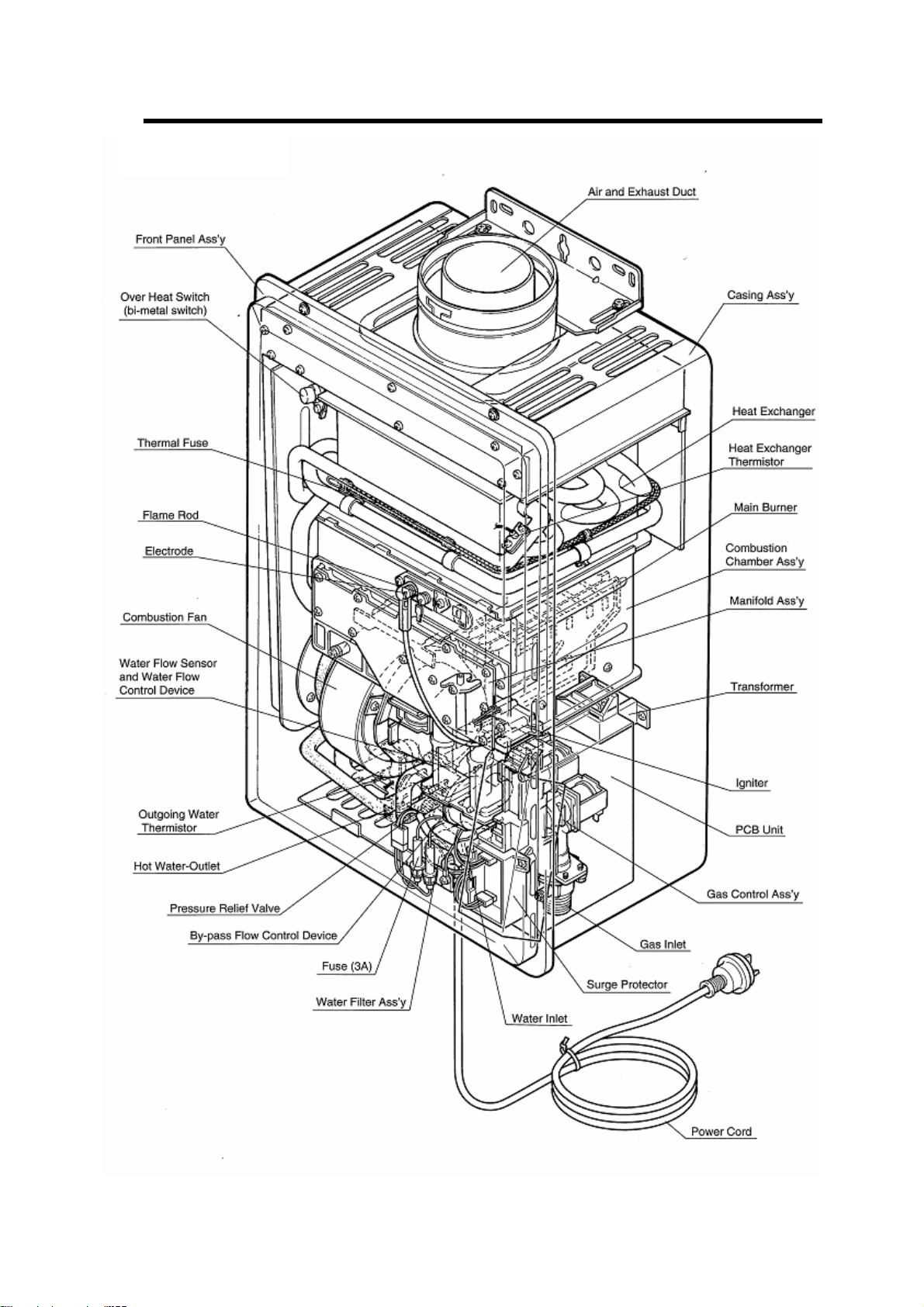
7. Cutaway Diagram
Infinity REU-V2632FFUG / HD200i REU-VM2632FFUC - 10 - Issue 1 - 16/12/09 ©Rinnai
 Loading...