

Rinnai REU-AM2626WDL, REU-AM2626WD, REU-AM2024WD, REU-AM1620WD, REU-AM1220WD User Manual
...

Congratulations on the purchase of your Rinnai Gas Continuous Flow Water Heater. We trust you will have many
IMPORTANT
years of comfort and enjoyment from your appliance.
BEFORE USING THIS APPLIANCE
Before proceeding with the operation or installation read this manual thoroughly and gain a full
understanding of the appliance, to ensure safe and correct use.
This appliance must be installed in accordance with:
• Manufacturer’s Installation Instructions
• Current AS/NZS 3000, AS/NZS 3500 & AS/NZS 5601
• Plumbing Code of Australia (PCA)
• Local Regulations and Municipal Building Codes
including local OH&S requirements
This appliance must be installed, maintained and removed
by an Authorised Person.
For continued safety of this appliance it must be installed
and maintained in accordance with the manufacturer’s
instructions.
All Rinnai gas products
sold in Australia are
A.G.A. certified.
Rinnai 2 HW_CF OIM

OPERATION TABLE OF CONTENTS
Warnings & Important Information 4
Before Using This Appliance .............................................................................................................................................. 4
Regulatory Information ....................................................................................................................................................... 4
Notice to Victorian Consumers .......................................................................................................................................... 4
Warning About Hot Water ................................................................................................................................................... 4
Operational Safety Information ......................................................................................................................................... 5
.............................................................................................................................................................7
Water Temperature Control 8
Maximum Delivery Temperatures ....................................................................................................................................... 8
Operation Without Water Controllers ................................................................................................................................ 8
Rinnai Water Controllers ................................................................................................................................................... 8
Location ............................................................................................................................................................................. 8
Water Resistance .............................................................................................................................................................. 8
Temperature Control ......................................................................................................................................................... 9
........................................................................................................................................ 9
Universal Water Controller (MC-601Q) Operation ......................................................................................................... 10
...................................................................................................................................................................... 10
.................................................................................................................................................... 10
......................................................................................................................................................... 10
............................................................................................................ 10
Smartstart Pre-Heat System ..............................................................................................................................................11
..............................................................................................................................................................11
............................................................................................................................................................11
Water Controller Functions ...............................................................................................................................................11
Trouble Shooting 12
Error Codes ........................................................................................................................................................................ 12
.............................................................................................. 13
.................................................................................................................... 13
Service ................................................................................................................................................................................ 13
Installation Table of Contents 14
Contacts 36
Rinnai 3 HW_CF OIM

WARNING
WARNING
WARNING
WARNINGS & IMPORTANT INFORMATION
BEFORE USING THIS APPLIANCE
Before proceeding with the operation or installation read this manual thoroughly and gain a full
understanding of the appliance, to ensure safe and correct use.
Always comply with the following precautions to avoid dangerous situations and to ensure
optimum performance.
Failure to carefully read and follow all instructions in this manual can result in equipment
malfunction, property damage, personal injury and/or death.
DANGER: Indicates an imminently hazardous situation which, if not avoided, will result in
personal injury or death.
WARNINGS: Indicates a potentially hazardous situation which, if not avoided, could result in
personal injury or death.
CAUTIONS: Indicates a potentially hazardous situation which, if not avoided, could result in
minor or moderate injury or damage to the appliance. It may also be used to alert against unsafe
practices.
REGULATORY INFORMATION
This Appliance must be installed correctly by an appropriately licensed tradesperson. The
installation of gas, water, and electricity must conform to local regulations.
The installation of gas, water, and electricity must conform to local regulations, including local
OH&S requirements. The installation must also comply with the instructions supplied by Rinnai.
Please keep this instruction booklet in a safe place for future reference.
Notice to Victorian Consumers
This appliance must be installed by a person licensed with the Victorian Building Authority. Only
a licensed person will have insurance protecting their workmanship. So make sure you use a
For further information contact the Victorian Building Authority on 1300 815 127.
WARNING ABOUT HOT WATER
Hot water can cause scalding. Those most
at risk are children and disabled, elderly and
burn a child in half a second).
Rinnai have water heater models which
Temperature limiting devices may also be
information.
ALWAYS test the water temperature before
entering a shower, to ensure it is suitable
for the application and will not cause scald
injury.
ALWAYS supervise children whenever
they are in the bathroom or near other
sources of hot water. Ensure any hot water
Rinnai 4 HW_CF OIM

Operational Safety Information
IMPORTANT
This appliance is not intended for use by persons (including children) with reduced physical,
sensory or mental capabilities, or lack of experience and knowledge, unless they have been given
supervision or instruction concerning use of the appliance by a person responsible for their
safety. Children should be supervised to ensure that they do not play with the appliance.
To clean your water controller(s) use a soft damp cloth
with a mild detergent.
use solvents!
Depending on the weather conditions and the length
of the pipe between the hot water unit and the
outlet in use, there may be a variation between the
temperatures displayed at the water controller(s) and
the temperature of the water at the outlet.
Whilst hot water outlets are open the set temperature
may be lowered. However they cannot then be raised
above 43°C. In addition transfer of 'priority' between
controllers is not possible. These are safety features.
after use. However, if you prefer to turn the water
maximum of 50°C will be stored in the system memory
at all times whilst mains power remains connected.
As a safety precaution, if a Kitchen Water Controller's
temperature is set above 50°C, transferring and then
Controller when the water heater ‘In Use’ indicator is
returning 'priority' to the Kitchen Water Controller will
result in a set temperature of 50°C being selected.
the water to go cold. Someone maybe in the middle of
When 'priority' is returned to Water Controllers other
than the Kitchen the temperature will be 42°C.
Rinnai 5 HW_CF OIM

IMPORTANT
heaters is available from Rinnai.
43°C 55°C
If the supply cord is damaged, it must be replaced by the manufacturer, its service agent or
Always check water temperature carefully before use.
Refer to the on
page 4 for important safety information.
OFF!
without warning. Opening the tap further will restart
the heating appliance.
HOT!
appliances and does not indicate a fault.
gas, and drain all water from the appliance. If power
and the automatic frost protection are connected,
freezing will be prevented. (Anti-frost protection is
Spray aerosols in the vicinity of this appliance
while it is in operation.
this appliance.
place articles on or against this appliance.
modify this appliance.
store pool chemicals near this appliance.
The delivered water temperature is controlled
delivery temperature selected and the ambient water
temperature.
Rinnai 6 HW_CF OIM

FEATURES & BENEFITS
heater.
•
water and gas supplies are connected, hot water is available whenever hot water taps are open.
Built into the main micro-processor is the facility to LIMIT THE MAXIMUM TEMPERATURE of the hot
•
water supplied. The water temperature may be limited to various values. This is particularly useful when the
of hot water. Whilst electricity,
•
makes them COMPACT
The temperature of hot water is by a . If the temperature
•
of the hot water rises to more than 3°C above the selected temperature the burner is turned OFF and only
turned ON again when the temperature falls below the selected temperature.
The burner lights automatically when the hot water tap is opened, and goes out when the tap is closed.
•
'Deluxe' or 'Universal' Water Controllers are available as an optional extra. Depending on the models chosen,
•
-
Voice Prompting (Deluxe Control Only).
-
Clock (Deluxe Control Only).
-
-
For further information regarding Wireless and Deluxe water controllers please contact Rinnai or visit
www.rinnai.com.au.
•
the hot water outlets. This results in water savings and reduces waiting time for heated water at the outlets.
Operating .
•
•
The (REU-AM2626WDL) water heater model is supplied with one "MC-503" wireless
•
water controller kit that includes a transceiver and a wireless water controller, that is pre-programmed as a
master controller. Additional "MC-503" wireless water controllers are available as an optional extra. Please
refer the separate wireless operation manual for instructions on how to use the supplied wireless water
controller.
Rinnai 7 HW_CF OIM
on the Water Controllers and Status Monitor*, assisting with

NOTE
NOTE
NOTE
WATER TEMPERATURE CONTROL
MAXIMUM DELIVERY TEMPERATURES
This does not apply to “50 degree compliant” models. To meet the regulatory requirements the
maximum delivery temperature is factory set and sealed.
refer to "Table 2. Maximum Delivery Temperatures" on page 31. The appliance model number
can be found on the dataplate, which is located on the left hand side of appliance.
OPERATION WITHOUT WATER CONTROLLERS
Rinnai WATER CONTROLLERS
Other manufacturers water controllers are NOT compatible with Rinnai water heaters. Rinnai
water controllers brought in from other countries are also NOT compatible with Rinnai appliances
sold in Australia.
Water controllers MUST NOT be used with any Solar Boost water heater.
Location
Water Resistance
Controllers MUST BE installed at least 400 mm above the highest part of a sink, basin or bath.
DO NOT immerse the water controller into water.
AVOID direct exposure to water or steam as these conditions may cause a malfunction.
ALWAYS AVOID exposure to water when the battery compartment is open.
When cleaning your water controller use ONLY a damp cloth and a mild detergent.
Rinnai 8 HW_CF OIM

Temperature Control
NOTE
NOTE
IMPORTANT
IMPORTANT
Whilst hot water outlets are open ONLY the control used to set to delivery may be used to further
adjust it. Transfer of 'priority' between controllers is NOT possible until all hot water taps have
been closed. These are safety features.
The temperature of outgoing hot water is constantly monitored by a built-in sensor. If the
•
•
will automatically go out. The ‘in use’ indicator will also go out. The burner will ignite again
once the outgoing hot water temperature falls to that shown on the digital monitor (or the pre-set
limit of the appliance)
*
heaters can be programmed to deliver higher temperatures from the master water controller,
or may be programmed to restrict the maximum available delivery temperature. Contact
Rinnai for more details.
**
temperature is available to outlets.
www.rinnai.com.au
REU-VCM2837FF/FFC FOUR
As REU-VCM2837FF/FFC
THREE, with the built-in controller acting
as a FOURTH controller.
•
•
controller, this is the default setting and can NOT be changed.
TWO
FOURTH MUST BE

UNIVERSAL WATER CONTROLLER (MC-601Q) OPERATION
NOTE
CAUTION
PREHEAT INDICATOR
Indicates that the Smartstart preheater (when fitted) is
activated.
PREHEAT BUTTON
Used to start and stop the Smartstart preheat unit (when
fitted), See Smartstart Operation on page 11.
CONTROLLER PRIORITY INDICATOR
Indicates if this water controller is in control of water
delivery temperature.
PRIORITY TRANSFER BUTTON
Used to tra nsfe r cont rol prio rity betwe en w at er
contr ollers. The wa ter con troller with priority has
command of the hot water delivery temperature.
Turning On
Adjusting Temperature
or
WATER HEATER 'IN USE' INDICATOR
Indicates that a water heater is delivering hot water.
DIGITAL MONITOR
Indicates the temperature selected.
Error messages flash in event of a fault.
TEMPERATURE CONTROL BUTTONS
Used to select water temperature.
WATER HEATER ON INDICATOR
Indicates that the hot water heater is on.
ON/OFF BUTTON
Used to switch the water heater on and off.
ON!ON!
COLDCOLD
or
all hot water taps have been closed.
Temperatures higher than 50ºC MUST NOT be able to be selected on controllers installed in
bathrooms, ensuites or toilets. This is to help reduce the risk of burns from hot water. If this is not
the case, the controllers have been incorrectly installed. CONTACT YOUR INSTALLER.
The 'beep' sound can be muted by pressing the and buttons simultaneously for more than
3 seconds. To cancel sound muting, simply repeat the process.
Always check outlet water temperature before use. The parent / carer MUST check the temperature
before placing dependants in contact with hot water, see "Warning About Hot Water" on page 4.
Transferring Priority
HOTHOT
Rinnai 10 HW_CF OIM

SMARTSTART PRE-HEAT SYSTEM
NOTE
The “Preheat” function works in conjunction with various Rinnai water heater models when the separately installed
and optional Rinnai “Smartstart®” module is installed.
1
Preheat Button
Used to start and stop Smartstart preheater
2
7
2
1
5
8
Preheat Function
When the "Preheat" function is activated and used in accordance with these instructions, water in the pipework
connected between the water heater and the hot water outlets in your house is warmed before any outlets are
opened. This results in water savings and added convenience.
3
6
9
4
Preheat Indicator
Indicates that Smartstart preheater is activated*
3
Digital Monitor
4
5
Controller Priority Indicator
6
Temperature Control Buttons
7
Water Heater "In Use" Indicator
8
Priority Transfer Button
9
Water Heater On Indicator
Preheat Operation
1. Ensure that the hot water unit is on (temperature digits are displayed in the digital monitor 3). If more than
8
to pass on priority to your desired water
controller. The "Controller Priority" indicator
water controller and that the hot water unit is ready to deliver hot water.
2. Select the desired temperature using the "Temperature Control" buttons 6 until the required temperature is
displayed in the digital monitor 3.
3. Press the "Preheat" button 1 once. The "Preheat" indicator 2 and the "In Use" indicator 7 will illuminate,
signifying that the preheat system has been activated.
4. Wait for the "In Use" indicator
the water in the pipework has now been pre-warmed and is ready for delivery, and that a hot water tap can
now be opened.
For best results always wait for the "In Use" indicator 7 to go out before opening a hot water tap.
The preheat function is cancelled 5 minutes after activation and the "Preheat" indicator 2 will go
out. This is to conserve energy. To reactivate, simply repeat steps 2-4 above.
If the "Preheat" button 1 is pressed and the 'Smartstart' preheat unit is not installed, the "Preheat"
indicator 2 will still light however there will be no preheat function. The "Preheat" indicator 2
heater.
function wait 30 seconds before activating the 'Preheat' function. Attempting to use the 'Preheat'
function earlier will result in voice prompts being repeated until the system is reset. The system
7
5
Water Controller Functions
Water controller functions such as temperature control and transfer of priority between multiple controllers are not
Rinnai 11 HW_CF OIM
NOTE
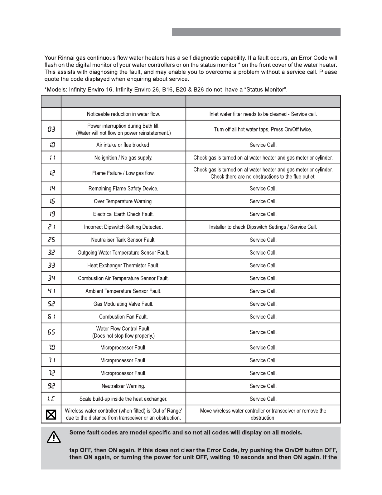
TROUBLE SHOOTING
ERROR CODES
Code Description Remedy
-
In the majority of cases, you may be able to clear the Error Code simply by turning the hot water
Error Code still remains, contact Rinnai for advice.
Rinnai 12 HW_CF OIM
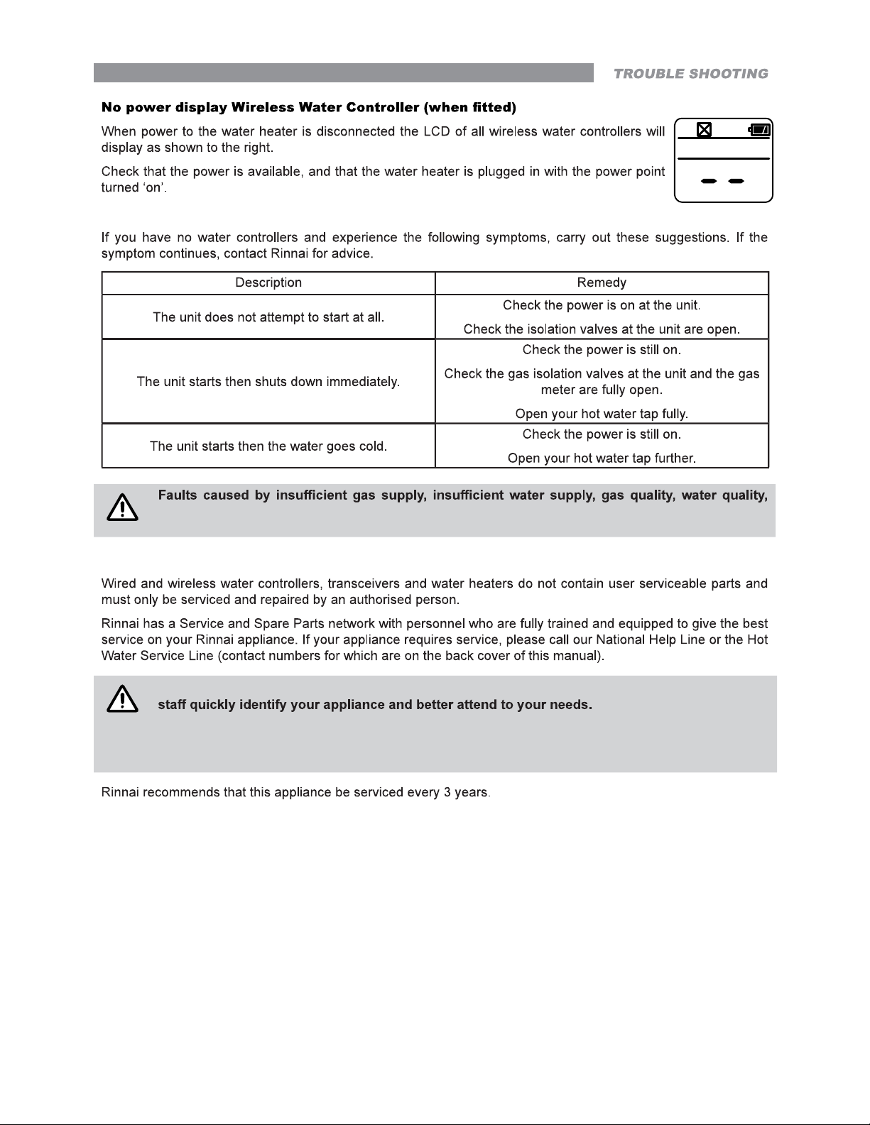
Troubleshooting Without Water Controllers
NOTE
NOTE
installation errors or operation errors are NOT covered by the Rinnai warranty. Refer to separate
warranty booklet for details.
SERVICE
When making a service enquiry, having both the model and serial numbers available, will help our
This information should have been copied to the "Installation Record" on page 30 by your
installer, however if this is not the case, the information can also be found on the data plate
located on the left hand side of the appliance.
Rinnai 13 HW_CF OIM

INSTALLATION TABLE OF CONTENTS
Operation Table of Contents 3
Regulations ........................................................................................................................................................................ 16
Applicable Models ............................................................................................................................................................. 16
Appliance Location ............................................................................................................................................................ 16
Outdoor Models ............................................................................................................................................................... 16
Indoor Models ................................................................................................................................................................. 16
Mounting Of Appliance .................................................................................................................................................... 17
Service Connection Points ............................................................................................................................................. 17
Pipe Sizing ...................................................................................................................................................................... 17
Water Supply ................................................................................................................................................................... 17
Altitude Setting REU-VCM ONLY .................................................................................................................................... 18
Hot Water Delivery Temperature ...................................................................................................................................... 18
............................................................................................................................................... 18
Flueing 19
Appliance Flue Terminal ................................................................................................................................................... 19
Horizontal Obstructions ................................................................................................................................................... 20
Sideways Flue Diverter - All models except REU-VCM .................................................................................................. 20
Multiple Appliance Installations ....................................................................................................................................... 20
............................................................................................................... 21
Basic methods of installation .......................................................................................................................................... 21
Flue Length Dipswitches ................................................................................................................................................. 21
Multiple Terminal Installations ......................................................................................................................................... 21
.................................................................................................... 22
Length & Changes Of Direction ...................................................................................................................................... 22
Installation Method ............................................................................................................................................................ 22
Interconnection Of Condensate / Neutraliser Drain Lines ............................................................................................... 23
Common Stack Discharge .............................................................................................................................................. 23
Tundish Drain Lines ........................................................................................................................................................ 23
Areas Subject To Freezing .............................................................................................................................................. 23
Rinnai 14 HW_CF OIM

Water Controller Installation 24
........................................................................................................................................................... 24
Master / Sub Water Controllers & Associated Temperatures .......................................................................................... 24
Water Controllers Limitations .......................................................................................................................................... 24
Location ........................................................................................................................................................................... 25
Communication Cables ................................................................................................................................................... 25
Joining Communication Cables (REU-A / REU-AM) ....................................................................................................... 25
Connecting Communication Cable(s) With 'Ezi connect' (REU-A / REU-AM) ................................................................ 26
Connecting Communication Cables to Mini-Plug (REU-E & REU-VCM) ........................................................................ 26
Connecting Communication Cables to PCB (REU-E & REU-VCM) ................................................................................ 27
Universal Water Controller (MC-601Q) Installation ........................................................................................................ 27
Additional Programming & Activation Requirements ....................................................................................................... 28
Commissioning 29
Testing ................................................................................................................................................................................29
Delivery Temperature ........................................................................................................................................................ 29
50°C Compliant Models .................................................................................................................................................. 29
For All Other Models ...................................................................................................................................................... 29
....................................................................................................................................................... 30
Wiring Diagram .................................................................................................................................................................. 30
Commissioning Check List ............................................................................................................................................... 30
Installation Record ............................................................................................................................................................ 30
Table 1. Supply, Flow rates, Weights & Service Connections ....................................................................................... 31
Table 2. Maximum Delivery Temperatures ...................................................................................................................... 31
.................................................................................. 32
Table 4. Appliance Dimensions - B Series & Universal Water Controller ..................................................................... 34
Table 5. Other Accessories ............................................................................................................................................... 35
Contacts 36
Rinnai 15 HW_CF OIM

WARNING
GENERAL INSTALLATION INFORMATION
MUST
ONLY.
Remove transit protection. Check for damage, if any is found DO NOT install and contact supplier.
REGULATIONS
This appliance must be installed in accordance with:
Current AS/NZS 3000, AS/NZS 3500 and AS/NZS 5601
•
Rinnai Installation Instructions
•
Plumbing Code of Australia (PCA)
•
Local regulations and municipal building codes including local OH&S requirements
•
APPLICABLE MODELS
the cover page of this manual.
APPLIANCE LOCATION
This appliance MUST BE
Rinnai for further information.
MUST BE provided adjacent to the appliance. For outdoor installations
MUST BE MUST BE
This appliance MUST BE
Refer to AS/NZS 5601 Section 6 for details.
All appliances MUST BE
means of scissor or boom lifts or other approved safe access equipment that is acceptable to local authorities.
This appliance
Models other than REU-VCM are suitable for installation locations up to 1000 metres above sea level and are
suitable for alpine areas.
REU-VCM models are suitable for installation locations higher than 1000 metres above sea level such as alpine
areas, refer to "Altitude Setting REU-VCM ONLY" on page 18 for further information.
Outdoor Models
This appliance is designed for ‘Outdoor’ Installation only. As such, it MUST BE located in an above ground open
MUST BE
Indoor Models
This appliance is designed for ‘Indoor’ installation only. It may be installed ‘Outdoors’ in an enclosure if the
Rinnai 16 HW_CF OIM

MUST BE made for the safe disposal of any
Rinnai internal models described in this manual MUST
This appliance MUST BE
FFWALLTERM or vertical (roof) FFROOFCOWL terminals are available for this purpose. The location of these
terminals MUST BE
Mounting Of Appliance
MUST BE
section 6. Wooden plugs shall be used.
Service Connection Points
MUST BE
personal hygiene. Refer to "Hot Water Delivery Temperature" on page 18.
Pipe Sizing
regulator MUST BE
Water Supply
MUST
MUST
Rinnai 17 HW_CF OIM

Altitude Setting REU-VCM ONLY
IMPORTANT
WARNING
WARNING
IMPORTANT
Diagram 2 :
NOT
a 50°C Appliance
NOTE
NOTE
REU-VCM models are suitable for installation locations higher than 1000 metres above sea level
such as alpine areas. To ensure proper appliance operation the installer MUST select one of the
two available altitude ranges for the appliance these are:
'DEFAULT' suitable for installation locations that are from 0 to 900 metres
above sea level.
'HIGH' suitable for installation locations that are from 901 to 1800 metres
above sea level, as would be typical of installations located in alpine areas.
Refer to "Commissioning Instructions" located inside the appliance front
Default
DipSW1
OFF ON
DipSW2
OFF ON
6
6
High
DipSW1
OFF ON
DipSW2
OFF ON
6
6
cover for details.
HOT WATER DELIVERY TEMPERATURE
This appliance may deliver water at high temperature. Refer to the Plumbing Code of Australia
(PCA), local requirements and installation instructions to determine if additional delivery
temperature control is required.
Local regulations and or the requirements of AS/NZS 3500 MUST be addressed regarding the temperature
areas may be limited to 50°C or less. To ensure these regulations and or requirements are met the system MUST
This appliance MUST
is
control is inadequate.
If the appliance is to deliver water primarily for the purposes of personal hygiene in an early
childhood centre, primary or secondary school, nursing home or a similar facility for the care of
(TLD), such as a Tempering Valve may be required even if the appliance is set to 50º C or less. For
these types of applications contact Rinnai.
Diagram 1 : 50°C Appliance
ENSUITE
50º C
LAUNDRY
BATHROOM
KITCHEN
Minimum length of pipe from hot outlet
to nearest hot water tap 2 metres.
Water controller
(optional)
Water controller
(optional)
Water controller
(optional)
Water controller
(optional)
Water controller
(optional)
KITCHEN
Water controller
(optional)
LAUNDRY BATHROOM
TLD = Temperature Limiting Device.
Water controller
ENSUITE
TLD
(optional)
Water controller
(optional)
Rinnai 18 HW_CF OIM

APPLIANCE FLUE TERMINAL
Below eaves, balconies and other projections:
a
For appliances up to 50 MJ/h input 200
For appliances over 50 MJ/h input
From a gas meter (M) (see Note 5)
d
(see Clause 5.11.5.9 for vent terminal location of regulator)
(see Table 6.7 for New Zealand requirements)
From an electricity meter or fuse box (P) † (see Note 5)
e
Horizontally from any building structure* = or obstruction facing a terminal
g
From any other flue terminal , cowl, or combustion air intake *
h
Horizontally from an openable window, door, non-mechanical air inlet, or any other opening into a
building with the exception of sub-floor ventilation:
Appliances up to 150 MJ/h input *
Appliances over 150 MJ/h input up to 200 MJ/h input * 300
j
Appliances over 200 MJ/h input up to 250 MJ/h input *
Appliances over 250 MJ/h input * 1500
All fan-assisted flue appliances, in the direction of discharge
Vertically below an openable window, non-mec hanical air inlet, or any other opening into a
building with the exception of sub-floor ventilation:
Space heaters up to 50 MJ/hr input
n
Other appliances up to 50 MJ/hr input
Appliances over 50 MJ/h input and up to 150 MJ/h input
Appliances over 150 MJ/h input
* Unless appliance is certified for closer installation.
† Prohibited area below electricity meter or fuse box extends to ground level.
NOTES:
Where dimensions c, j or k cannot be achieved an equivalent horizontal distance measured
1
diagonally from the nearest discharge point of the terminal to the opening may be deemed by
the Technical Regulator to comply.
See Clause 6.9.4 for restrictions on a flue terminal under a covered area.
2
See Figure J3 for clearances required from a flue terminal to an LP Gas cylinder. A
3
flue terminal is considered to be a source of ignition.
For minimum clearances not addressed above acceptance should be obtained from the
4
Technical Regulator.
Minimum clearances d and e also apply to any combustion air intake openings of appliances.
5
FLUEING
Min. Clearances
(mm)
metI.feR
epip lios ro epip niard a morFf
Fan
assisted
300
300* ecafrus rehto ro ynoclab a evoba ,dnuorg eht morFb
300* renroc lanretxe ro llaw nruter a tnorFc
1000
500
75
500
300
300
500
1500
1000rewolb aps a gnidulcni ,telni ria lacinahcem a morFk
150
500
1000
1500
FIGURE 6.2 (in-part) LOCATION OF FLUE TERMINALS OF BALANCED FLUE,
ROOM-SEALED, FAN-ASSISTED OR OUTDOOR APPLIANCES
HW_CF OIM

Horizontal Obstructions
IMPORTANT
WARNING
DipSW
DipSW
and obstruction facing the terminal.
500mm
MINIMUM OBSTRUCTION
HEIGHT IS TO BE NO LESS
THAN TOP OF APPLIANCE
MUST ‘obstruct’
the full front cover height of the appliance (for appliance dimensions, refer to "Table 3. Appliance Dimensions -
There MUST be NO partial obstructions to the front cover of the appliance or any other parts
of the appliance casing. This will avoid the appliance failing to operate under windy conditions.
Sideways Flue Diverter - All models except REU-VCM
MUST also
CONTROL BOARD DIPSWITCH SETTING (NOT REU-VCM):
The installer MUST follow the Sideways Flue Diverter instructions of the "Commissioning Check
List" provided on the front cover of the appliance and the "Commissioning Instructions" located
in the inside the appliance front cover.
When delivered ex-factory ALL the
switches of the control board dipswitch
are set to OFF (left position).
the installer MUST set switches SW1
and SW3 to ON (right position) ONLY.
Improper setting of the switches will cause the appliance to operate incorrectly.
Multiple Appliance Installations
of the same model are installed on the same vertical
Under these conditions appliances can abut each other
For appliance dimensions, refer to "Table 3. Appliance
SW1 (OFF)
SW2 (OFF)
SW3 (OFF)
SW4 (OFF)
ON
SW1 (ON)
SW2 (OFF)
SW3 (ON)
SW4 (OFF)
Factory Default Sideways Flue Diverter
ON
Universal Water Controller" on page 34.
Rinnai 20 HW_CF OIM

INFINITY-i / HD-i INTERNAL MODELS - CO-AXIAL FLUE
IMPORTANT
IMPORTANT
275
Rinnai internal models described in this manual MUST
and violates regulations.
MUST be installed in accordance with the ‘Rinnai FFU Flue Installation
accordance with the FFU Flue Installation Manual.
Basic methods of installation
1
methods available, these are:
1
Direct Horizontal
2
Extended Horizontal
3
Vertical
4
Combined Vertical / Horizontal
Flue Length Dipswitches
Installations can consist of both horizontal and
vertical runs.
MUST NOT exceed 15
2
4
3
DipSW1
Short Flue Extended Flue
OFF ON
OFF ON
1 2 3 4 5 6 7 8
1 2 3 4 5 6 7 8
run MUST NOT exceed four, noting that each
& 3, where
1
NOT exceed 7 metres, the
& 4,
2
SW1 of both DipSW1 & DipSW2 are set to 'OFF'.
Refer to the 'Rinnai FFU Flue Installation Manual'
Multiple Terminal Installations
The terminal clearances stated in AS/NZS 5601 do not apply
they are installed side by side.
For all other appliance dimensions, refer to "Table 3. Appliance
Controller" on page 34.
DipSW1
DipSW2
150
85
DipSW2
Short Flue Extended Flue
OFF ON
FF
FF
OFF ON
1 2 3 4 5 6 7 8
FF
FF
FFROOFCOWL
Minimum
Clearance
500
FFWALLTERM
1 2 3 4 5 6 7 8
FFWPLATE
195
Rinnai 21 HW_CF OIM

NOTE
B
A
C
REU-E MODEL NEUTRALISER TANK & DRAIN
MUST
IMPORTANT CONSIDERATIONS FOR NEUTRALISER DRAIN PIPE
Lines’ has been used as a guide in preparing these considerations.
Remove cap from condensate drain outlet
Length & Changes Of Direction
INSTALLATION METHOD
A
D
E
2°
MUST BE
8 7
Rinnai 22 HW_CF OIM

Interconnection Of Condensate / Neutraliser Drain Lines
Common Stack Discharge
Tundish Drain Lines
Areas Subject To Freezing
HW_CF OIM

IMPORTANT
IMPORTANT
IMPORTANT
IMPORTANT
WATER CONTROLLER INSTALLATION
GENERAL INFORMATION
Other manufacturers water controllers are NOT compatible with Rinnai water heaters. Water
controllers MUST NOT be used with any Solar Boost water heater. Rinnai water controllers
brought in from other countries are not compatible with Rinnai appliances sold in Australia.
Regardless of water controller installation, all Rinnai water heaters must only be installed by an
Authorised person.
Water controllers, transceivers and water heaters DO NOT contain user serviceable parts and
must ONLY be serviced and repaired by an authorised person.
Master / Sub Water Controllers & Associated Temperatures
Only one MC model water controller can be designated as the 'Master' water controller. This water controller is
kitchen applications. Temperatures higher than 55°C are possible but usually unnecessary and will result in higher
gas use and increase the risk of burns.
Some additional conditions regarding Master Controller maximum temperatures apply when a wireless water
controller is used as the 'Master' water controller.
(i) Temperatures of 55°C or higher can only be selected on the controller designated as the 'Master' water
controller if the transceiver 'Max Temp' is also programmed to 55°C or higher.
(ii) The temperature of hot water delivered is always limited to the maximum temperature programmed into the
water heater itself. For example, if the transceiver maximum temperature is programmed to 55°C and the
water heater is limited to 50°C, the maximum temperature that the water heater will deliver is 50°C. In this
case 55°C will be displayed on the wireless Master Controller until a tap is opened after which the display will
revert to 50°C.
The water heater maximum temperature cannot be adjusted by the user. These adjustments can
ONLY
The remaining water controllers are designated 'sub' controllers and are for use in bathrooms, toilets and laundries.
The temperature limit for all 'Sub' controllers is always 50°C to minimise the risk of burns in these areas.
(Bathroom) water controllers. These labels are usually placed on the top back of the wireless water controller body.
Water Controllers Limitations
For all models except REU-VCM2837FF/FFC a maximum of FOUR
•
As REU-VCM2837FF/FFC
THREE, with the built-in controller acting
as a FOURTH controller.
Only master controller can be installed. This can be a deluxe kitchen (MC-100V), or any other MC
•
model water controller (when programmed to be a 'Master' controller).
controller, this is the default setting and can NOT be changed.
A up to a maximum of TWO BC-100V water controllers can be installed.
•
The FOURTH water controller in any installation MUST BE a MC-601Q or a MC-503RC-S.
•
Rinnai 24 HW_CF OIM

Location
NOTE
NOTE
• DO NOT install water controllers near a heat source, such as a cook top, stove or oven. Heat,
steam, smoke and hot oil may cause damage.
• DO NOT install water controllers outdoors unless protection from water / dust ingress and
sunlight are provided.
• The water controller set as the MASTER water controller MUST NOT be installed in a
bathroom.
• DO NOT install water controllers in direct sunlight.
• DO NOT install water controllers against a metal wall unless the wall is earthed in accordance
• Water controllers MUST NOT be installed where chemicals such as benzene, alcohol,
turpentine, hydrogen sulphide, ammonia, chlorine or other similar chemicals are in use.
The Water controller is a water resistant device, however excessive exposure to water may result
in damage to the water controller. Durability is improved when positioned outside the shower
recess.
• AVOID direct exposure to water or steam as these conditions may cause a malfunction.
•
MUST BE installed at least 400 mm above the highest part of a sink, basin or bath.
• When cleaning your water controller use ONLY a damp cloth and a mild detergent.
For water controller dimensions refer to "Table 4. Appliance Dimensions - B Series & Universal
Water Controller" on page 34.
Communication Cables
Wired water controllers operate at an extra low voltage (12 Volts DC) which is supplied from the water heater,
a 10 metre long communications cable is supplied for connection to the water heater. Rinnai supplied
communication cables may be used.
Optional longer per metre communication cabling Part No. 92078609 is available from Rinnai.
The per metre communication cable does not come supplied with spade connectors, spade
connectors are available from your local electrical component retailer.
Joining Communication Cables (REU-A / REU-AM)
A
so
that there are only two sets of spade connectors (4 spade connectors in total) to be terminated (spade connectors
are available from your local electrical component retailer).
When
Terminating
Three Cables
A
When
Terminating
Four Cables
A
A
Follow steps 1 through 5 of "Connecting Communication Cable(s) With 'Ezi connect' (REU-A / REU-AM)" on page
26 to terminate the joined cable pairs to the water heater.
Rinnai 25 HW_CF OIM
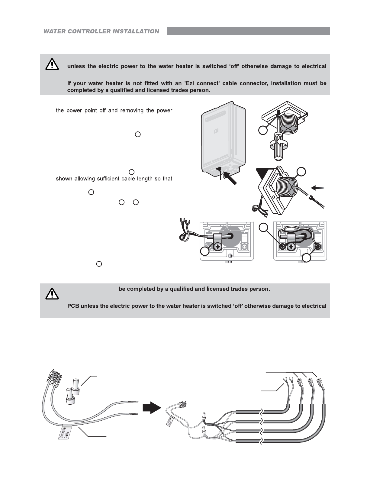
Connecting Communication Cable(s) With 'Ezi connect' (REU-A / REU-AM)
CAUTION
CAUTION
DO NOT attempt to connect cables to the 'Ezi connect' cable connector at the water heater
components may occur.
1. Isolate the electric power supply by switching
plug of the water heater from the electric power
socket.
2. Remove the retaining screw A of the 'Ezi
connect' cable connector at the base of the
appliance.
3. Swing the 'Ezi connect' cable connector door
open and thread the cable through the weather
seal of the cable access hole B in the direction
the sheath of the cable can be secured with
cable clamp C.
4. Loosen screw terminals D & E and connect
the cable spade connectors to these terminals
and re-tighten.
Polarity is not important, either wire colour can
be connected to either terminal.
5. Return the 'Ezi connect' cable connector to
the original position taking care not to damage
cable wires in the process and replace the
retaining screw A.
C
A
D
B
E
Connecting Communication Cables to Mini-Plug (REU-E & REU-VCM)
Installation MUST
DO NOT attempt to connect water controller cables to the mini-plug when it is plugged into the
components may occur.
Water controllers are connected to the PCB via a dedicated pre-wired mini-plug (supplied).
Use the supplied electrical cable connectors to terminate the water controller wires to those of the mini-plug. The
existing spade connectors of the communication cables will need to be removed prior to termination. Controllers
are not polarity sensitive, however to avoid confusion it is recommended that like coloured wires be terminated
together.
Electrical Connectors
(Supplied with Water Controllers)
Pre-wired Mini-Plug
(Supplied)
Communications Cable
MC-91Q, MC-601Q, BC-100V
Communications Cable
MC-100V, MC-503RC-M
Rinnai 26 HW_CF OIM

Connecting Communication Cables to PCB (REU-E & REU-VCM)
CAUTION
Installation MUST be completed
person.
DO NOT attempt to connect miniplug or water controller cables
to the water heater unless the
electric power to the water heater is
electrical components may occur.
1. Isolate the electric power supply by
the power plug of the water heater from
the electric power socket.
2. Remove the front cover of the appliance.
3. Insert the mini-plug and the connected
water controller cables through the cable
access A at the base of the appliance.
Ensuring that the cable connectors are
located inside the appliance for protection.
4. Locate the PCB B, (bottom right of
appliance), and carefully rotate the plastic
safety cover C out of the way.
5. Locate the accessory port socket D
(bottom front of the PCB).
REU-VCMREU-E
REU-VCM PCB
B
A
B
C
A
REU-E shown, REU-VCM is similar.
D
B
D
6. Plug the mini-plug into the accessory port
socket D (the plug and socket are keyed
so that they can only be plugged in the one
direction).
7. Proceed with the water controller
installation and connect the communication
cables to controllers.
UNIVERSAL WATER CONTROLLER (MC-601Q) INSTALLATION
1. Determine the most suitable position, refer "Location" on page 25.
2. Mark and drill 3 holes (mounting and cable access) refer to page 34 for water controller dimensions.
Controller Cable
Connector
Fig. 1 Fig. 2 Fig. 3 Fig. 4
3. When running cable through the access hole ensure the connector end of the cable is located nearest to the
water controller (Fig. 1).
4. Carefully remove the cover plates from the water controller, using a screw driver (Fig. 2).
5. Connect the cable to the water controller. Feed any excess cable lengths into the wall cavity to avoid the
pinching of cables between the wall and the water controller.
6.
7.
Screws
REU-E PCB
Film
Cover
Plates
Rinnai 27 HW_CF OIM

Additional Programming & Activation Requirements
QUESTION
QUESTION
NOTE
?
IF NO:
IF YES:
STEP 1:
STEP 2:
?
IF YES:
IF NO:
STEP 1:
STEP 2:
You have three (or fewer) water controllers, go to Question 2.
(approximately 5 seconds).
Check that the display on ALL FOUR water controllers is lit and displaying a
two dashes (see Fig. 2) repeat STEP 1.
This completes the activation procedure for the fourth water controller, you
may ignore Question 2.
No further action required..
You will need to program the kitchen water controller to enable selection of
temperatures higher than 50°C.
(approximately 5 seconds).
possible to select temperatures higher than 50°C. If not, repeat STEP 1.
Fig. 1
Fig. 2
Fig. 3
If the water controller in the kitchen is replaced, repeat STEP 1 for the replacement water
controller.
If the water controller in the kitchen is swapped with another water controller (for example, the
STEP 1 for the water controller moved from the
kitchen to the bathroom. Then perform STEP 1 for the water controller moved from bathroom
to the kitchen.
Rinnai 28 HW_CF OIM

TESTING
IMPORTANT
CAUTION
NOTE
1.
2.
3.
4.
except REU-VCM" on page 20 for details.
5.
6.
ALL
Ensure building occupants DO NOT have access to hot water outlets during this procedure.
7. ALL
8.
COMMISSIONING
ALL
The gas regulator on the appliance is electronically controlled and factory pre-set. Under normal
circumstances it DOES NOT need adjustment during installation.
9.
11.
12.
13.
DELIVERY TEMPERATURE
50°C Compliant Models
For All Other Models
Rinnai 29 HW_CF OIM

GAS PRESSURE SETTING
NOTE
For all injector size and gas pressure values refer to the appliance data plate, located on the left
hand side of the water heater.
WIRING DIAGRAM
COMMISSIONING CHECK LIST
INSTALLATION RECORD
Installer Details
DOES NOT
ONLY
System Details
REU-
* This information will need to be copied from the data plate, located on the left hand side of appliance.
HW_CF OIM

SPECIFICATIONS
TABLE 1. SUPPLY, FLOW RATES, WEIGHTS & SERVICE CONNECTIONS
Water
Weight
Hot
kPa kg
TABLE 2. MAXIMUM DELIVERY TEMPERATURES
(a) Factory "Pre-Set" Maximum delivery temperature (°C)
(b) Can the Factory "Pre-Set" Maximum delivery temperature be changed by an authorised person?
No No No No No No No No No No No No No
Rinnai 31 HW_CF OIM

TABLE 3. APPLIANCE DIMENSIONS - INFINITY, ENVIRO, INFINITY-i & HD
A Width
B
Height Unit
Hot water outlet
E
87 87 87 87 87 96
F
G 68 68 68 68 68
H
I 77 77 77 77 77
89 89 89
K
N 68 68
P
Rinnai 32 HW_CF OIM

Infinity Series Infinity Enviro Series
A
B
A
B
DC
M
E
G
I
E
H
F
J
Infinty-i / HD-i Series (Internal)
A
B
L
H
F
J
HD-e Series (External)
A
DC
M
K
G
I
B
N
DC
M
E
H
F J
Rinnai 33 HW_CF OIM
IG
E
H
F J
DC
M
IG

TABLE 4. APPLIANCE DIMENSIONS - B SERIES & UNIVERSAL WATER CONTROLLER
B Series
A
DC
A Width
B
Height Unit
B
M
Hot water outlet
E
F
G 68 68 68
H
I 77 77 77
K
N
87 87 87
E
G
H
F
J
Universal Water Controller - MC-601Q
A
I
C
B
O
P
P
Drawings are not to scale
Rinnai 34 HW_CF OIM

TABLE 5. OTHER ACCESSORIES
Pipe
Cover
heater and are designed to conceal pipes and valves.
Pipe covers may also be joined to one another to conceal longer
Security
Cage and damage.
Security
Flue
Diverter
*
Smart Box
**
Recess Box
Recess boxes are also suitable for painting.
**
**
Water
Controllers available.
www.rinnai.com.au.
REU Series Pipe Cover
REU-AM PCD01
REU-E PCD08
REU-A PC11D
All Models
CAGE01
All Models
SECBKT
REU Series Diverter
REU-AM SFD-01
REU-E SFD-04
REU-A SFD-01/02/03 *
Rinnai 35 HW_CF OIM

U340 —1330X03(00)
06000012378283
36 HW_CF_A_AM_E_VCM OIM Issue 4 - /06/2021
 Loading...