

Rinnai REU V2632FFUC, REU V2632FFU Installation Instruction
Flueing Installation Instructions for
Internally installed Water Heater
Models REU V2632FFU / REU V2632FFUC
This Flue shall be installed in accordance with: -
Manufacturer’s Installation Instructions
Local Gas Fitting Regulations
Municipal Building Codes
AGA Installation Code for Gas Burning Equipment
Any other relevant Statutory Regulation
This appliance and flue system must be installed,
serviced and removed by an Authorised Person.
UP
UP
UP
Distributed and Serviced in Australia under a Quality
system certified as complying with ISO 9002 by
Standards Australia Quality Assurance Services
.

Flueing Installation Instructions
Contents:
General...................................................................................................................2
Important Installation Notes ...................................................................................2
Flueing Options ......................................................................................................3
Installation Tips ......................................................................................................3
Direct Flueing With Wall Terminal..........................................................................4
Extended Horizontal Flueing With Wall Terminal ..................................................4
Vertical Straight Flueing With Roof Terminal.........................................................5
Combination Vertical / Horizontal Installations ......................................................6
Multiple Vertical / Horizontal Installations ..............................................................7
Cutting The Flue Components. ..............................................................................7
Condensate drain...................................................................................................8
Flue Dimensions & Part Numbers .........................................................................9
Minimum Flue Clearances .....................................................................................10
Contact Points........................................................................................................10
Installation
This flue must be installed by an authorised person, the Installation must conform to local
regulations. Installation must comply with the instructions supplied by Rinnai.
Service and removal must be carried out by an authorised person.
Approval
Approved by AGA as a suitable flueing system for Rinnai REU V2632FFU / REU V2632FFUC
Gas Internal Water Heaters.
General
1. These instructions only apply to Rinnai Infinity Flueing with white plastic outer pipe. These instructions do not
apply to Rinnai Infinity Flueing with the stainless steel single skin or stainless steel coaxial flue. If in doubt
contact the Rinnai Australia Technical Advice Helpline: 1300 366 388.
2. Before commencing installation, please read the 'Installation Instructions - General', located inside a pouch
behind the front cover of all Infinity models. The Internal Infinity Range of water heaters must only be installed
with Rinnai Infinity Fluing as referred to in these instructions.
3. The requirements of the current AS5601/AG601 and local authorities must be met, which is the installers
responsibility.
4. The Required clearances of the Internal Rinnai Infinity when installed as a single unit are shown in Fig.1A The
appliances are AGA certified to be installed side by side as shown on
between flues.
270mm between horizontal terminals.
160mm between vertical cowls.
5. The REU-V2632FFU/REU-V2632FFUC when correctly installed with the Rinnai approved flue components is a
room-sealed appliance. No internal ventilation is required.
6. The fan assisted flue clearance dimensions in Fig 5 should be used, as the REU2632FFU is a fan-assisted
appliance.
7. The outer plastic section of the coaxial flue complies with temperature hazard requirements and can be
installed with zero clearance to combustible material.
, allowing a Minimum distance
page 7
Rinnai Aust ralia Pty Lt d 20/08/2003 Page 2 of 10
Flueing Installation Instructions
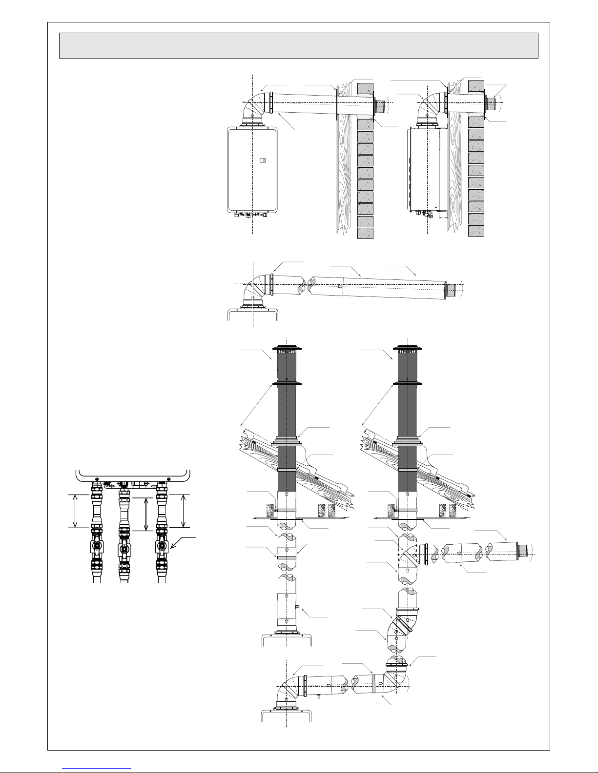
Flueing Options
Direct Flueing with Wall
1.
Terminal: (Fig.1)
Horizontal Extension Flueing
2.
with Wall Terminal: (Fig.2).
3. Vertical Flueing with Roof
Terminal (Fig.3)
4. Vertical / Horizontal Flueing with
Bends Wall and Terminal or
Roof Terminal (
Fig.4).
UP
FFBEND90BA
FFWPLATE or
FFWSEAL (Optional)
FFWALLTERM
127mm Hole
FFWPLATE or FFWSEAL (Optional)
FFBEND90BA
2° fall
to
terminal
FFWPLATE
UP
127mm Hole
2° fall
to
terminal
FFWPLATE
50
Fig.1
Installation Tips
1. The use of soft liquid soap on
the rubber seals will allow the
fittings to easily slide together.
(It is important to use soft soap,
2.
e.g.: Liquid hand soap, as hard
detergents may damage the
seals and PVC outer section).
3. Rinnai recommend 100 mm of
pipe (gas and water) section
between the isolating valves and
the appliance, which when
removed will allow the Infinity to
be lowered and disconnected
from the flue. (Fig. 5).
100
100
100
Valves
UP
FFROOFCOWL
FFBEND90BA
FFPIPE1000
U
P
FFROOFCOWL
FFWALLTERM
2° fall
to
terminal
Fig.2
Minimum
Clearance
500 mm
Flue pipe clip
supplied with
FFPIPE1000
Flue pipe clip
supplied with
FFPIPE1000
Decktite or lead
collar flushing
Flue pipe clip
supplied with
FFROOFCOWL
UP UP
UP
FFWSEAL FFWSEAL
FFPIPE1000
UP
Minimum
Clearance
500 mm
Flue pipe clip
supplied with
FFPIPE1000
FFPIPE1000
FFBEND90
FFPIPE1000
Decktite or lead
collar flushing
Flue pipe clip
supplied with
FFROOFCOWL
FFWALLTERM
U
U
P
UP
P
FFPIPE1000
2° fall
to trap
GasColdHot
Fig.5
4. When cutting any section of the
flue, remove all burrs and file a
slight bevel on the outer edge to
reduce any damage to the seal
when inserting into the
connecting fitting.
(See the section ‘Cutting the
Flue Components’ (Fig.9).
Rinnai Aust ralia Pty Lt d 20/08/2003 Page 3 of 10
Fig.3
UP
UP
UP
FFCONDK
FFBEND90BA
U
P
FFPIPE1000
Flue pipe clip
supplied with
FFPIPE1000
FFBEND45
(x2 = 90° Bend)
U
P
UP
UP
UPU
P
UP
U
P
FFPIPE1000
2° fall
to trap
FFBEND90
Fig.4
 Loading...