

Rinnai Infinity V26 series, Infinity Heavy Duty 26 series, REU-V2626W series, REU-V2632W series Installation Information
Local regulations and / or the requirements of AS/NZS 3500.4 must be
considered regarding the temperature limitations of hot water supplied to
areas used primarily for personal hygiene. The temperature of water to
these areas may be limited to 50º C or less. To ensure these regulations
and / or requirements are met the system MUST be installed in
accordance with the 'Water Heater and Controller Installation
Configurations' Section of this document.
The appliance weighs 21 kg and the wall or structure on which it is to be
mounted must be capable of supporting the weight of the appliance and
associated pipe-work.
Ensure that suitable fixing screws or bolts are used to secure the Infinity
to the wall. Bracket and fixing hole locations are shown overleaf.
The top bracket has a keyhole slot so that the appliance can be
positioned by hanging it on one screw, then the other screws can be
secured.
After determining the most suitable position, fix the Infinity to the wall.
Positions of the cold water inlet, hot water outlet and gas connections are
shown overleaf. All connections are R ¾ (20mm). This is NOT an
indication of the pipe sizes required.
An Approved isolation valve and disconnection union MUST be fitted to
the cold water inlet. A non return valve is not required unless dictated by
local regulations.
GENERAL INSTALLATION INFORMATION
REU-V2626W SERIES / REU-V2632W SERIES
AG601/AS5601 - Gas Installations
AS/NZS 3500 - National Plumbing and Drainage
AS/NZS 3000 - Wiring Rules
Building Codes of Australia
The appliance should be placed as close as practicable to the most
frequently used hot water outlet point or points to minimise the delay
time for hot water delivery. For installations where the distance between
the unit and hot water outlet points is considerable, the appliance can
also be fitted in a 'flow and return system' which minimises the waiting
time for hot water delivery. Alternatively, multiple appliances can be
strategically placed to service outlet points with minimal delay time.
Contact Rinnai Australia for further information.
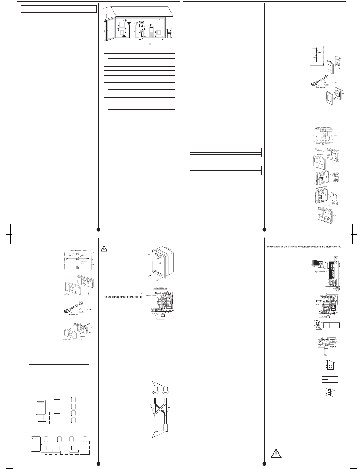
Location of the appliance flue terminal must be in accordance with the
clearances shown in Figure 5.3 of AG601/AS5601-2002 which is
reproduced right side. Ensure that the flue terminal and hot water outlet
connection cannot be touched by children. The appliance must be clear
of obstructions and shrubbery.
The appliance must be in an accessible location. Sufficient clearances
shall allow access to, and removal of, all serviceable components. The
appliance should not be mounted higher than 3.5 metres from the
ground or floor level unless the customer can arrange permanent and
safe access or can arrange another means of access, for example, by
means of scissor or boom lifts.
AC 240V, 10A weatherproof external earthed power point shall be
provided adjacent to the appliance. It must be clear of the gas and water
connections to the appliance, flue exhaust and water pressure relief
valve. The power cord of the appliance is 1500 mm long.
Note that AG601/AS5601-2002 was current at the time of printing but
may have been superseded. It is the installer's responsibility that the
current clearance requirements are met.
This appliance can use up to 199 MJ/h of gas. If the gas pipe sizing is
insufficient the customer will not get the full performance benefit. Gas
pipe sizing must consider the gas input to this appliance as well as all
the other gas appliances in the premises. The gas meter and regulator
must be specified for this gas rate. An approved sizing chart such as the
one in AG601 / AS5601 should be used.
Water pipe sizing and layout should be performed in accordance with
AS/NZS 3500. All hot water pipe-work should be insulated to optimise
maximum performance and energy efficiency.
Where the water supply pressure exceeds 1200 kPa, an approved
pressure limiting valve is required at the inlet of the appliance. To
achieve the rated flow a minimum water supply pressure of 140 kPa is
required at the appliance inlet. The unit will operate at lower supply
pressures but the rated flow will not be achieved. Contact Rinnai for
'gravity fed' or 'low pressure' hot water installations.
The water quality should be in accordance with the guidelines contained
in the 'How to use your Water Heater' booklet. Most Australian
Metropolitan water supplies will fall within these guidelines. If you are
unsure of your water quality, contact your local water authority. If sludge
or foreign matter is present in the water supply, a suitable filter should be
incorporated in the cold water supply pipe.
You must install this appliance in accordance with these Instructions and all
regulatory requirements which exist in your area. Applicable publications
may include:
•
•
•
•
THIS APPLIANCE IS DESIGNED FOR OUTDOOR INSTALLATION.
IT MUST BE MOUNTED ON A VERTICAL WALL OR STRUCTURE WITH
THE WATER AND GAS CONNECTIONS ON THE UNDERSIDE POINTING
TOWARDS THE GROUND.
THIS APPLIANCE MUST NOT BE USED AS A DOMESTIC SPA OR
SWIMMING POOL HEATER.
APPLIANCE LOCATION
PIPE SIZING
WATER SUPPLY
*Contact Rinnai for exemptions for the above clearances which may have
been granted since printing of this document.
HOT WATER DELIVERY TEMPERATURE
MOUNTING THE APPLIANCE
SERVICE CONNECTION POINTS
Min. clearances
(mm)
Ref.
Item
Fan assisted
Below eaves, balconies and other projections:
•
Appliances up to 50 MJ/h input
200
a
•
Appliances over 50 MJ/h input
300
b
From the ground, above a balcony or other surface †
300
c
From a return wall or external corner †
300
d
From a gas meter (M) (see 4.7.11 for vent terminal location of
regulator)
1000
e
From an electricity meter or fuse box (P)
500
f
From a drain pipe or soil pipe
75
g
Horizontally from any building structure = or obstruction facing a
terminal
500
h
From any other flue terminal, cowl, or combustion air intake†*
300
Horizontally from an openable window, door, non-mechanical air inlet, or any other opening
into a building with the exception of sub-floor ventilation:
•
Appliances up to 150 MJ/h input
300
•
Appliances over 150 MJ/h input up to 200 MJ/h input
500
•
Appliances over 200 MJ/h input
1500
j
•
All fan-assisted flue appliances, in the direction of disc harge
1500
k
From a mechanic al air inlet, including a spa blower
1000
Vertically below an openable window, non-mechanic al air inlet, or any other opening into a
building with the exception of sub-floor ventilation:
•
Space heaters up to 50 MJ/h input
150
•
Other appliances up to 50 MJ/h input
500
•
Appliances over 50 MJ/h input and up to 150 MJ/h input
1000
n
•
Appliances over 150 MJ/h input
1500
†
- unless appliance is approved for closer installation
NOTES:
1 All distances are measured to the nearest part of the terminal.
2 Prohibited area below electricity meter or fuse box extends to ground level.
3 See Clause 5.13.6.6 for restrictions on a flue terminal under a covered area.
4 See Appendix J, Figures J2(a) and J3(a), for clearances required from a flue terminal to an LP Gas
cylinder. A flue terminal is considered to be a source of ignition.
5 For appliances not addressed above, approval shall be obtained from the Authority.
g
openable
window
door
M
P
g
See note 3
T
b
d
d
e
e
See note 2
h
h
a
h
j
j
j
n
k
k
c
c
f
T = Flue terminal
I
= Mechanical air inlet
areas for flue terminals
T
T
I
Shading indicates prohibited
M = Gas meter
P = Electricity meter or fuse box
Fig 5.3
1
An Approved isolation valve and disconnection unit MUST be fitted to
the gas inlet.
Isolation Valves must not be fitted directly to the appliance.
It may be necessary to fit a temperature limiting device for delivery to
areas used primarily for the purposes of personal hygiene. Refer to the
'Water Heater and Controller Installation Configurations' Section of this
document.
Purge gas and cold water supply lines to remove air and swarf before
final connection of the appliance. Swarf in either the gas or water
supplies may cause damage.
Recess Box: The appliance can be 'recessed' into the wall for flush
fitting reducing even further the space required. A custom made Rinnai
Infinity Recess Box must be used for this purpose.
Pipe Cover: The pipe-work underneath the appliance can be covered
using a custom made Rinnai pipe cover.
Security Cage: A Security Cage can be fitted around the appliance.
Contact Rinnai for further details.
Remote Controllers are an optional extra. 'Standard' and 'Deluxe'
controls can be fitted. Standard controls allow temperature selection
only. Deluxe controls have temperature selection, bath-fill and voice
prompting functions. For detailed information regarding controller
operation refer to the 'How to use your water heater' booklet supplied
with the appliance. Other manufacturers' controllers are NOT compatible
with this appliance.
Up to 4 Standard Controls can be fitted to the appliance. They are
normally installed in the areas where the majority of hot water is used,
for example, the kitchen, bathroom, ensuite and laundry.
Deluxe controllers have 'kitchen' (MC-70-2A) and 'bathroom' (BC-70-2A)
versions. 'Kitchen' controls are intended for the kitchen or other
convenient area where the majority of hot water is used. Bathroom
controllers are intended to be fitted in the bathroom or ensuite and allow
the user to have a bath filled to the required level and temperature
automatically.
Up to three 'deluxe' controllers can be connected as follows:
If a fourth controller is required, a Standard controller can be included as
follows:
Controllers must be installed in shaded and clean locations. They should
be fitted out of reach of children (suggested height from floor at least
1500mm). Controllers are water resistant, however, durability is
improved when positioned outside the shower recess or at least 400mm
above the highest part of a sink, basin or bath.
NEAR A HEAT SOURCE, SUCH AS A COOK TOP, STOVE OR OVEN.
HEAT, STEAM, SMOKE AND HOT OIL MAY CAUSE DAMAGE.
IN DIRECT SUNLIGHT.
OUTDOORS UNLESS AN ENCLOSURE IS PROVIDED WHICH
PROTECTS THE CONTROLLER AGAINST SUNLIGHT AND DUST
INGRESS.
AGAINST A METAL WALL UNLESS THE WALL IS EARTHED IN
ACCORDANCE WITH AS/NZS 3000.
Remote controls operate at extra low voltage (12 Volts DC) which is
supplied from the appliance. Controllers are supplied with 15 m of
electrical cable. The cable wires for connection to the appliance are
fitted with spade terminals. Extension cables are available from Rinnai.
Alternatively, a two core sheathed (double insulated) flex with minimum
cross-sectional area of 0.5 mm² can be used. Maximum cable length is
50 m. For connection refer to the “CONNECTING REMOTE CONTROL
CABLES” section.
Determine the most suitable position for the Remote Control.
Determine the most suitable position for the Remote Control.
ACCESSORIES
REMOTE CONTROLLERS
STANDARD CONTROLLER (MODEL MC-91-1A)
DELUXE CONTROLLERS (MODELS MC-70-2A AND BC-70-2A)
POSITIONING OF CONTROLLERS
DO NOT INSTALL THE CONTROLLERS:
•
•
•
•
REMOTE CONTROL CABLES
FITTING THE 'STANDARD' REMOTE CONTROLLERS (MC-91-1A)
1.
2.
3.
4.
5.
6.
7.
8.
Note: For details on how to program the MC-91-1A remote control see
Appendix 1. MC-91-1A CONTROLLER PROGRAMMING.
FITTING THE 'DELUXE' REMOTE CONTROLLERS (MC-70-2A)
1.
2.
3.
4.
5.
6.
7.
8.
9.
10.
Kitchen
Bathroom
Ensuite
MC-70-2A
MC-70-2A BC-70-2A
MC-70-2A
BC-70-2A BC-70-2A
Drill 3 holes in the wall, as shown in
fig.1, one for the cable and two for
the securing screws. Ensure holes
are drilled. Fit wall plugs if required.
Run the cable through the hole in the
wall-ensuring that the end fitted with
the connector is near the controller.
(fig.3)
Remove the face plate from the Remote
Control, using a screw driver.(
fig.2)
Connect the cable to the remote
controller.
Fix the remote controller to the wall
and fasten with phillips head screws
supplied as shown in fig.4.
Remove the protective plastic film from
the controller face as show in fig.4
Replace the face plate.
Drill 3 holes in the wall, as shown in
fig.1, one for the cable and two for
the securing screws. Ensure holes
are drilled. Fit wall plugs if required.
Fix the mounting bracket to the wall
using the screws provided.
Run the cable through the hole in the
wall.
Remove the face plate from the
Remote Control, using a screw driver.
(fig.2)
Connect the cable to the kitchen
remote control as shown in fig.3.
Connect cables from bathroom
controllers (if fitted) to the kitchen
remote control also (if required).
Polarity is not important; either colour
wire can be connected to either
terminal.
Fix the kitchen controller to the wall
bracket and fasten with phillips head
screws supplied (M4 x 12) as shown
in fig.4.
Remove the protective plastic film
from the controller face as shown in
fig.5.
Replace the face plate.
Close the flip panel.
Note: If the cable cannot be run in the
wall cavity, remove the plastic 'knockout'
lugs as shown in fig.3.
Kitchen Bathroom
Ensuite Laundry
MC-70-2A
MC-70-2A BC-70-2A
MC-70-2A BC-70-2A BC-70-2A MC-91-1A
Outline of Remote Control
90
Securing
Wire
fig.1
fig.3
fig.5
fig.4
fig.3
fig.2
fig.1
fig.2
Face Plate
fig.4
Face Plate
Screw
2
Drill 3 holes in the wall, as shown in
fig.1, one for the cable and two for
the securing screws. Drill holes to
ensure controller position will be level
when installed. Fit wall plugs if
required.
Run the cable through the hole in the
wall - ensuring that the end fitted with
the connector is near the controller.
(fig.3)
Remove the face plate from the
Remote Control, using a screw driver.
(fig.2)
Connect the cable to the bathroom
remote controller.
Fix the bathroom controller to the wall
and fasten with phillips head screws
supplied as shown in fig.4.
Remove the protective plastic film
from the controller face as shown in
fig.4.
Replace the face plate.
Close the flip panel.
Determine the most suitable position for the Remote Control.
If the front cover of the appliance contains the following text install it in
accordance with Diagram 1 below.
" THIS APPLIANCE DELIVERS WATER
NOT EXCEEDING 50ºC IN ACCORDANCE WITH AS 3498 "
If the front cover of the appliance does NOT contain the above text install
it in accordance with Diagram 2 below.
IMPORTANT: If the appliance is to deliver water primarily for the
purposes of personal hygiene in an early childhood centre, primary or
secondary school, nursing home or similar facility for young, aged, sick
or disabled persons as defined in AS/NZS 3500.4 a Temperature Limiting
Device (TLD), such as a Tempering Valve, may be required even if the
appliance is set to 50º C or less.
For these types of applications contact Rinnai.
Diagram 1 - 50ºC Appliance.
Diagram 2 - Not a 50ºC Appliance.
Note: TLD = Temperature Limiting Device.
Isolate the power supply.
Remove the front cover from the Appliance (4 screws) fig. 1.
Cut the spade connectors from 2 of the controller cables to be
connected to the appliance (4 spade connectors should be cut off) and
discard. Connect the wires from these two cables and terminate into
two new spade connectors as shown in fig.3. Spade connectors are
available from your local electrical component retailer.
Thread the 3 cables through the cable access hole at the base of the
appliance. Connect the 4 spade connectors to the terminals marked
"Remote Control" on the printed circuit board. (fig. 2) Polarity is not
important. Either wire colour can be connected to either terminal.
Replace cover of the Appliance. Ensure that the screw with the star
washer is placed at the bottom right hand corner for earthing purposes.
Replace cover of the Appliance. Ensure that the screw with the star
washer is placed at the bottom right hand corner for earthing purposes.
FITTING THE 'DELUXE' REMOTE CONTROLLERS (BC-70-2A)
1.
2.
3.
4.
5.
6.
7.
8.
9.
WATER HEATER & CONTROLLER INSTALLATION CONFIGURATIONS
CONNECTING REMOTE CONTROL CABLES
RISK OF ELECTRICAL SHOCK !
Connecting One or Two Controllers
2.3.4.
5.
Connecting Three Controllers
1.
3.
4.
5.
Connecting Four Controllers
1.
2.
3.
4.
5.
Isolate the power supply.
Remove the front cover from the
Appliance (4 screws) fig. 1.
Thread the cable(s) through the cable
access hole at the base of the
appliance.
Connect the spade connectors to the
terminals marked
‘
Remote Control
Polarity is not important. Either wire
colour can be connected to either
terminal.
Replace cover of the Appliance.
Ensure that the screw with the star
washer is placed at the bottom right
hand corner for earthing purposes.
Isolate the power supply.
Remove the front cover from the
Appliance (4 screws) fig.1.
Cut the spade connectors from all
four controller cables to be connected
to the appliance (8 spade connectors
should be cut off) and discard.
Connect the wires from two cables
and terminate into two new spade
connectors as shown in fig.3.
Repeat for the remaining two cables.
Spade connectors are available from
your local electrical component
retailer.
Thread the 4 cables through the
cable access hole at the base of the
appliance. Connect the 4 spade
connectors to the terminals marked
‘"Remote Control" on the printed
circuit board. (fig. 2) Polarity is not
important. Either wire colour can be
connected to either terminal.
fig. 2
Do not attempt to connect the
remote control cable terminals to
the appliance with the power on.
fig. 3
New spade connectors
Cable
wires
Cable
wires
Remote control cables
50º C
KITCHEN
Temperature
controller
(optional)
Temperature
controller
(optional)
Temperature
controller
(optional)
Temperature
controller
(optional)
LAUNDRY
BATHROOM
ENSUITE
H
O
T
C
O
L
D
G
A
S
KITCHEN
Temperature
controller
(optional)
Temperature
controller
(optional)
LAUNDRY BATHROOM
Temperature
controller
(optional)
Temperature
controller
(optional)
ENSUITE
TLD
H
O
T
C
O
L
D
G
A
S
fig. 1
fig.3
CABLE CLAMP
REMOTE
REMO
fig.1
fig.2
fig.4
3
Regulator adjustment
screw access plug
TESTING AND COMMISSIONING
1.
2.
3.
4.
5.
6.
7.
8.
9.
10.
11.
12.
13.
GAS PRESSURE SETTING
Under normal circumstances it does not require adjustment during
installation. Perform this procedure only if the unit is not operating correctly
and all other possible causes for incorrect operation have been eliminated.
1.
2.
3.
4.
Note: 'ON' towards front, 'OFF' towards rear.
5.
6.
7.
8.
9.
10.
11.
12.
13.
14.
15.
16.
17.
18.
19.
20.
21.
Before final connection of the water heater purge gas, hot and cold
water supply lines. Swarf in either the gas or water supplies may cause
damage.
Turn on gas and cold water supplies.
Test for water leaks and gas escapes near the unit.
Isolate gas supply. Remove test point screw located on the gas inlet
connection and attach pressure gauge.
Turn the power 'on' at the power point socket and turn on gas.
If remote controllers are fitted, turn the controller 'on', select the
maximum delivery temperature and open ALL available hot water taps
including the shower. If remote controllers are not fitted, simply open all
available hot water taps. (CAUTION: Ensure building occupants do not
have access to hot water outlets during this procedure.)
Operate ALL other gas appliances at their maximum gas rate, in
accordance with manufacturers instructions.
With all gas appliances in operation at maximum gas rate, the pressure
gauge at the incoming test point the Infinity should read 1.13 - 3.0 kPa
on Natural Gas. On LPG the pressure should be 2.75 - 3.0 kPa. If the
pressure is lower, the gas supply is inadequate and the Infinity unit will
not operate to specification. Check gas meter, regulator and pipework
for correct operation/sizing and rectify as required. Note that the gas
regulator on the Infinity is electronically controlled and factory pre-set.
Under normal circumstances it DOES NOT need adjustment during
installation.
Close hot water taps including the shower.
Inspect and clean the strainer located on the cold water inlet
connection. This procedure may need to be repeated to ensure the
strainer remains clear, especially on new installations.
If Temperature Controllers are fitted, it is necessary to test their
operation through the complete range of functions. (Refer to the 'How to
use your Water Heater' booklet.)
Confirm the hot water delivery temperature(s) using a thermometer.
If controllers are fitted, ensure temperatures exceeding 50º C cannot be
selected on bathroom or ensuite controllers.
After testing is completed, explain to the householder the functions and
operation of the water heater and temperature controllers (if fitted).
Ensure the 'Customer Record' section of the 'How to use your Water
Heater' booklet is filled in and that the booklet is handed to the
customer. Remind the customer to complete the Warranty Card and
forward to Rinnai.
Turn 'OFF' the gas supply.
Turn 'OFF' 240V power supply.
Remove the front cover from the
appliance.
Check gas type switches (fig. 1) are in
the correct position (dipswitch 1 of
SW2 'ON' = NG, 'OFF' = LPG).
Attach pressure gauge to burner test
point, located on the gas control.
(fig. 2)
Turn 'ON' the gas supply.
Turn 'ON' 240V power supply.
If remote controllers are fitted, turn the
unit 'ON' at the kitchen controller,
select the maximum delivery
temperature of 55°C and open a hot
water tap fully. (CAUTION: Ensure
building occupants do not have access
to hot water outlets during this
procedure.)
Set the Infinity to 'Forced Low'
combustion by setting No. 7 dipswitch
of the SW1 set of dip switches to 'ON'.
(fig. 3)
Check the burner test point pressure.
Remove rubber access plug and
adjust the regulator screw on the
modulating valve (fig. 4) as required to
the pressure. Table 1. Replace rubber
access plug.
Set the Infinity to 'Forced High'
combustion by setting both No. 7 and
No. 8 dipswitches of the bottom SW1
set to 'ON'. (fig. 5) Ensure maximum
water flow.
Check the burner test point pressure.
Adjust the high pressure Potentiometer
(POT) on the Printed Circuit Board
(PCB) as required to the pressure
shown Table 2. (fig.1).
IMPORTANT: Set dip switches No's 7 and 8 on the bottom (SW1) set
of switches to 'OFF' to return the appliance to 'Normal' combustion.
(fig. 6)
Close hot water tap.
Turn OFF the gas supply and 240V power supply.
Remove pressure gauge, and replace sealing screw.
Turn 'ON' the gas supply and 240V power supply.
Operate unit and check for gas leaks at test point.
Replace the front cover of the appliance.
ON
fig. 3
fig. 4
Table 1.
N.G.
0.14 kPa
0.22 kPa
Prop.G.
Pressure Setting Low
ON
fig. 6
ON
fig. 5
Table 2.
N.G.
0.79 kPa
1.15 kPa
Prop.G.
Pressure Setting High
DURING PRESSURE TESTING OF THE INSTALLATION
ENSURE GAS COCK SITUATED BEFORE UNIT IS SHUT-OFF.
FAILURE TO DO SO MAY RESULT IN SERIOUS
DAMAGE TO THE APPLIANCE AND POSSIBLE INJURY.
SW2
g
fig.1
SW1
SW1
WARNING
Potentiometer
4
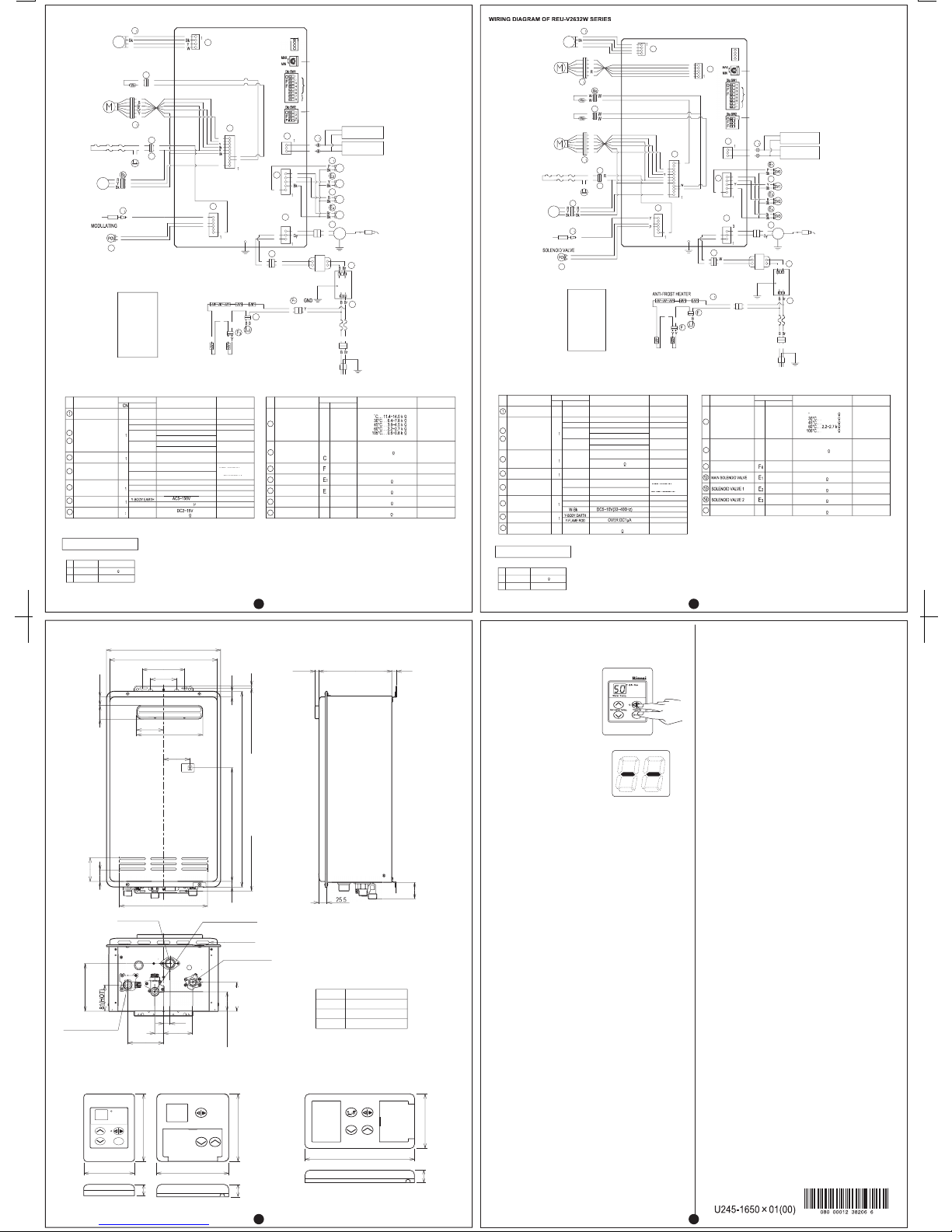
DIAGNOSTIC POINTS OF REU-V2632W SERIES
WIRING DIAGRAM OF REU-V2626W SERIES
DIAGNOSTIC POINTS OF REU-V2626W SERIES
TRANSFORMER
VOLTAGES AND RESISTANCES
FLOW
CHART
No.
COMPONENT
MEASUREMENT POINT
WIRE COLOR
A NOTE
SURGE PROTECTOR
AC207~264V
DC11~13V
REMOTE CONTROL
3
DC11~13V
3
WATER FLOW SENSOR
5
C
DC4~7V(PULSE 17~460Hz)
DC6~45V
67~81
MODULATING
SOLENOID VALVE
WATER FLOW
CONTROL DEVICE
Gy-Br
Gy-Y
BELOW DC1V(LIMITER ON)
DC11~13V
DC4~6V(LIMITER OFF)
FULL OPEN POSITION
DC11~13V
Gy-Or
OPERATE ELECTRICITY
BELOW DC1V(LIMITER ON)
DC4~6V(LIMITER OFF)
ON2.7l/min (30Hz)
OVER 1800PULSE/min
()
(
GND
5
COMBUSTION FAN
6
OVER DC1
µ
AFTER IGNITION
FLAME ROD
C
OFF2.0l/min (20Hz)
BELOW 1200PULSE/min
()
(
15
NORMAL VALUE
CONTROL ELECTRICITY
FULL CLOSE POSITION
FLAME CONDITION
GND
DC11~13V
DC5~10V(33~400Hz)
()
Y-FLAME ROD
16~18
WIRE COLOR
CN
5
NORMAL VALUE
AC90~110V
FLOW
CHART
No.
COMPONENT
MEASUREMENT POINT
CN
WIRE COLOR
A NOTE
Gy-Gy
6
IGNITER
MAIN SOLENOID VALVE
THERMAL FUSE
AC90~110V
DC80~110V
BELOW 1
8
10
13
15
3
OUTGOING WATER
THERMISTOR
DC80~110V
DC80~110V
DC80~110V
SOLENOID VALVE 1
SOLENOID VALVE 2
SOLENOID VALVE 3
ON MANIFOLD
NORMAL VALUE
3
9
FLOW
CHART
No.
COMPONENT
MEASUREMENT POINT
CN
WIRE COLOR
A NOTE
SURGE PROTECTOR
AC207~264V
DC11~13V
REMOTE CONTROL
DC11~13V
3
WATER FLOW SENSOR
5
6
C
DC4~7V(PULSE 17~460Hz)
DC6~45V
67~81
DC2~15V
MODULATING
SOLENOID VALVE
WATER FLOW
CONTROL DEVICE
Gy-Br
Gy-Y
BELOW DC1V(LIMITER ON)
DC11~13V
DC4~6V(LIMITER OFF)
FULL OPEN POSITION
DC11~13V
Gy-Or
OPERATE ELECTRICITY
BELOW DC1V(LIMITER ON)
DC4~6V(LIMITER OFF)
ON2.7L/min (30Hz)
OVER 1800PULSE/min
()
(
GND
5
COMBUSTION FAN
AC5~150V
AFTER IGNITION
FLAME ROD
C
8
OFF2.0L/min (20Hz)
BELOW 1200PULSE/min
()
()
G
Or-W
DC2~6V
15~35
GND
3
16
BY-PASS FLOW
CONTROL DEVICE
NORMAL VALUE
CONTROL ELECTRICITY
FULL CLOSE POSITION
OPERATE CONDITION
FLAME CONDITION
TRANSFORMER
VOLTAGES AND RESISTANCES
16~18
WIRE COLOR
CN
5
NORMAL VALUE
GND
DC11~13V
AC90~110V
FLOW
CHART
No.
COMPONENT
MEASUREMENT POINT
CN
WIRE COLOR
A NOTE
Gy-Gy
IGNITER
THERMAL FUSE
AC90~110V
DC80~100V
BELOW 1
9
15C11.4~14.0 k
6.4~7.8 k
3.6~4.5 k
0.6~0.8 k
OUTGOING WATER
THERMISTOR
5
DC80~100V
15
DC80~100V
DC80~100V
1.7~2.0k
HEAT EXCHANGER
OUTGOING THERMISTOR
SOLENOID VALVE 3
ON MANIFOLD
NORMAL VALUE
C
3
10
3
3
B
C
Gy
5
6
C
C
C
3
Gy
SV1
3
SV0
6
IG
SV2
Gy
Gy
TRANSFOMER
SURGE PROTECTOR
5
FUSE
(3A)
Gr/Y
Gr/Y
GND
ELECTRODE
SPARK
IGNITER
SV3
MAIN SOLENOID VALVE
SOLENOID VALVE 1
SOLENOID VALVE 2
SOLENOID VALVE 3
MODULATING VALVE
CURRENT ADJUSTING
Temperature control
Gas pressure
Gas type
OUTGOING WATER
THERMISTOR
WATER FLOW
CONTROL DEVICE
COMBUSTION FAN
THERMAL FUSE
OVERHEAT
SWITCH
QS
WATER FLOW
SENSOR
FLAME ROD
SOLENOID VALVE
BC-70-2A OR
MC-91-1A
COLOR CODING
W :White
Bk:Black
Br:Brown
R :Red
B :Blue
Y :Yellow
Or:Orange
Gr:Green
Gy:Grey
AC240V
Gr/Y
GND
ANTI-FROST HEATER
ANTI-FROST HEATER
FROST SENSING
SWITCH
MC-70-2A OR
MC-91-1A
10
3
C
Gy
Gy
5
3
6
3
C
C
C
3
Or
Gy
6
IG
Gy
TRANSFOMER
SURGE PROTECTOR
5
1
3
FUSE
(3A)
Gr/Y
GND
Gr/Y
GND
ELECTRODE
SPARK
IGNITER
MAIN SOLENOID VALVE
SOLENOID VALVE 1
SOLENOID VALVE 2
SOLENOID VALVE 3
MODULATING VALVE
CURRENT ADJUSTING
Temperature control
Gas pressure
Gas type
Or
OUTGOING WATER
THERMISTOR
HEAT EXCHANGER
THERMISTOR
BY-PASS FLOW
CONTROL DEVICE
WATER FLOW
CONTROL DEVICE
COMBUSTION FAN
THERMAL FUSE
OVERHEAT
SWITCH
QS
WATER FLOW
SENSOR
FLAME ROD
MODULATING
G
BC-70-2A OR
MC-91-1A
5
G
Or
RR
COLOR CODING
W :White
Bk:Black
Br:Brown
R :Red
B :Blue
Y :Yellow
Or:Orange
Gr:Green
Gy:Grey
AC240V
Gr/Y
GND
ANTI-FROST HEATER
3
FROST SENSING
SWITCH
MC-70-2A OR
MC-91-1A
5
WATER HEATER DIMENSIONS
REMOTE CONTROLLER DIMENSIONS
You will need to activate the fourth controller.
(You have 3 controllers or fewer), go to Question 2.
No further action required.
You will need to program the kitchen controller to enable
selection of temperatures higher than 50º C.
STEP 1:
For the controller in the KITCHEN only, press and hold the 'Transfer'
and 'On/Off' buttons simultaneously ( see fig.1 ) until a 'beep' is heard
(approximately 5 seconds).
STEP 2:
When the controller fitted in the KITCHEN is switched on, it should be
possible to select temperatures higher than 50º C. If not, repeat Step 1.
If the kitchen controller is replaced, repeat STEP 1 above for the
replacement controller.
If the kitchen controller is swapped with another controller (for
example, the controller fitted in a bathroom), repeat STEP 1 for the
controller moved from the kitchen to the bathroom. Then perform STEP
1 for the controller moved from the bathroom to the kitchen.
STEP 1:
For the controller in the KITCHEN
only, press and hold the 'Transfer'
and 'On/Off' buttons simultaneously
( see fig 1.) until a 'beep' is heard
(approximately 5 seconds).
STEP 2:
Check that the display on ALL FOUR
controllers is lit and displaying a
temperature when 'switched on'. If
any ONE of the controller displays
two dashes ( see fig 2. ) in the
display repeat STEP 1.
This completes the activation
procedure. Ignore question 2.
Appendix 1. MC-91-1A CONTROLLER PROGRAMMING
QUESTION 1: Are 4 controllers connected ?
IF YES:
IF NO:
QUESTION 2: Is your water heater labeled "THIS APPLIANCE
DELIVERS WATER NOT EXCEEDING 50º C IN
ACCORDANCE WITH AS 3498 " on the front cover ?
IF YES:
IF NO:
Note
·
·
fig 1.
fig 2.
195
22
97
120
120
12890
20
22
BC-70-2A
MC-70-2AMC-91-1A
89
20
HOT WATER OUTLET
GAS CONNECTION
COLD WATER INLET
CABLE ACCESS
350
330
A
270
81
82.5
203
80
Cold water inlet:20mm
Gas inlet :20mm
A Dimensions
GAS
COLD
40
50
6
87
 Loading...