

Page 1
Operation / Installation Manual
To Suit Models:
REU-V2520FFU........ R53
REU-V2520FFUC..... C53
REU-V2532FFU........ R85
REU-V2532FFUC...... C85
REU-V2520FFUD......
REU-V2520FFUCD... C53PLUS
REU-V2532FFUD...... R85PLUS
REU-V2532FFUCD... C85PLUS
(Residential and Commercial indoor unit)
R53PLUS
ANS Z21.10.3=CSA 4.3
WARNING: If the information in these instructions is not followed exactly, a re
or explosion may result causing property damage, personal injury or death.
– Do not store or use gasoline or other flammable vapors and liquids in the vicinity
of this or any other appliance.
– WHAT TO DO IF YOU SMELL GAS
Do not try to light any appliance.
•
• Do not touch any electrical switch; do not use any phone in your building.
Immediately call your gas supplier from a neighbor's phone. Follow the gas
•
supplier's instructions.
• If you cannot reach your gas supplier, call the fire department.
Installation and service must be performed by a qualified installer, service agency
–
or the gas supplier.
Page 2
V2532FFU
V2532FFUD
15,000
180,000
120°F 140°F 120°F 140°F
140°F 185°F 140°F 185°F
98°F 120°F
49 Lbs.
87%
49 dB (A)
Normal
75 watts
Standby
5.5 watts
Anti-frost Protection
100 watts
Electronic Fixed None
Natural Gas
6" W.C.
Propane
10" W.C.
Natural Gas
10.5" W.C.
Propane
13.5" W.C.
Ignition System
Water Temperature Control
Water Supply Pressure
Electric Connections
Minimum Water Pressure: 20 PSI (Recommended 30-80 PSI for maximum performance)
Safety Devices
Maximum Water Supply Pressure
Remote Control Cable
Flame Failure - Flame Rod
Boiling Protection - 210°F
Over Current - Glass Fuse (3 amp)
Remaining Flame (OHS) 207°F Bi-Metal Switch
Thermal Fuse 264°F
Direct Electronic Ignition
Appliance: AC 120 Volts, 60Hz. Remote Control: DC 12 Volts (Digital)
Simulation Feedforward and Feedback.
Gas Supply: 3/4" MNPT, Cold Water Inlet: 3/4" MNPT, Hot Water Outlet: 3/4" MNPT
Model
Minimum Gas Consumption Btu/h
Maximum Gas Consumption Btu/h
With or without remote controls, mounted in kitchen, bathroom, ect.
Connections
By-Pass Control
Minimum
Gas Supply
Pressure
Maximum
Gas Supply
Pressure
Type of Appliance
Operation
Exhaust System
Approved Gas Type
Electrical
Consumption
Hot water capacity, (50°F rise)
Hot water capacity, (35°F rise)
Default Temperature Setting (no controller)
Maximum Temperature Setting
Minimum Temperature Setting
Weight
Noise level
Efficiency Rating
Automatic Frost Protection - Bi-Metal Sensor & Anti-Frost Heaters
Combustion Fan RPM Check - Integrated Circuit
150 PSI
Non-Polarized Two Core Cable
0.6 to 5.3 GPM
0.6 to 5.3 GPM
Direct Vent - Forced Combustion
Natural Gas or Propane - Ensure unit matches gas type it's being installed on.
0.6 to 6.5 GPM
0.6 to 8.5 GPM
Temperature controlled continuous flow gas hot water system.
104°F 140°F 104°F 140°F
Controller Default Temperature Setting
V2532FFUC
V2532FFUCD
V2520FFU
V2520FFUD
V2520FFUC
V2520FFUCD
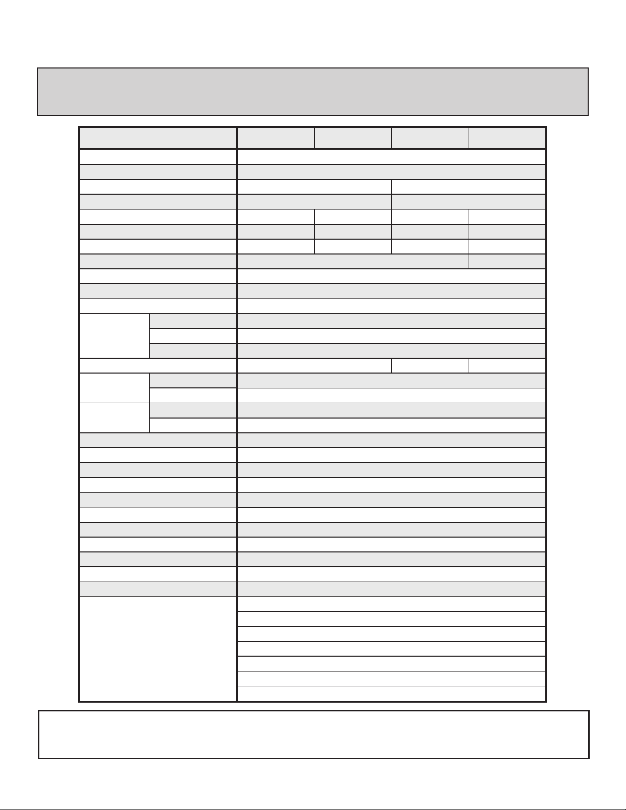
S P E C I F I C A T I O N S
NOT E: Rin na i is con ti nua ll y up da ti ng a nd i mp rov in g pr od uct s, the re fo re, spe ci fi cat io ns are
subject to change without prior notice. Local, state, provincial and federal codes must be adhered
to prior to installation.
Rinnai America
2
FF Models
Page 3
L I M I T E D W A R R A N T Y
R i n n a i W a t e r H e a t e r
WHAT IS COVERED?
This Warranty covers any defects in materials or workmanship when the product is installed and
operated according to Rinnai written installation instructions, subject to the terms within this limited
warranty document. This Warranty applies only to products that are installed by a state qualied
or licensed contractor. Improper installation may void this Warranty. Rinnai strongly suggests
that you use an installer who has attended a Rinnai product knowledge class before installing
this water heater. This Warranty extends to the original purchaser and subsequent owners, but
only while the product remains at the site of the original installation. This Warranty only extends
through the rst installation of the product and terminates if the product is moved or reinstalled at
a new location.
HOW LONG DOES COVERAGE LAST?
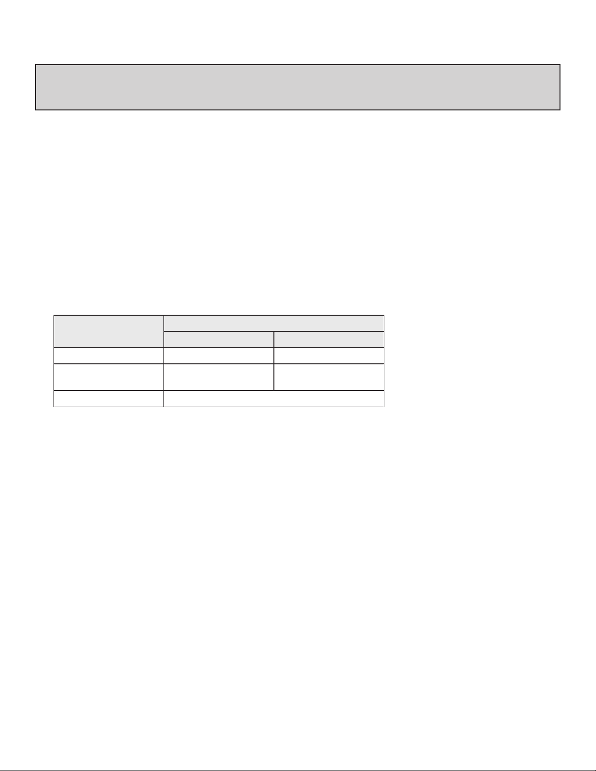
Warranty031705COMM-V2
Item
Commercial Residential
Heat Exchanger 5 Years* 10 Years*
All other Parts and
Components
Reasonable Labor 1 Year
Period of Coverage
5 Years* 5 Years*
*Important
Period of coverage is 3 years from date of purchase when used as a circulating water heater
within a hot water circulation loop, when the water heater is in series with a circulation system
and all circulating water ows through the water heater.
WHAT WILL RINNAI DO?
Rinnai will repair or replace the product or any part or component that is defective in materials
or workmanship, except as set forth below: Rinnai will pay reasonable labor and shipping costs
to repair the product. All repairs must be performed using genuine Rinnai parts. All repairs or
replacements must be performed by an individual or servicing company that is properly trained,
state qualied or licensed to do this type of repair.
Replacement of the product or replacement of the heat exchanger may be authorized by Rinnai
only. Rinnai does not authorize any person or company to assume for it any obligation or liability
in connection with the replacement of a product or heat exchanger. If Rinnai determines that
repair of a product is not possible, Rinnai will replace the product with a comparable product, at
Rinnai’s discretion. If a component or product returned to Rinnai is found to be free of defects in
material or workmanship, or damaged by improper installation or damaged during return shipping,
the warranty claim for product, parts and labor may be denied.
Rinnai America
3
FF Models
Page 4

L I M I T E D W A R R A N T Y
Ri nn ai Wat er H ea te r
Warranty031705COMM-V2
HOW DO I GET SERVICE?
Simply contact a qualied Service Dealer or Installer for the repair of products under this Warranty.
Failure to use a qualied Service Dealer or Installer to provide repair service may void the
Warranty. For the name of the qualied Service Dealer or Installer nearest you, please contact
the company that installed the water heater, or;
Your local HVAC/plumbing dealer, gas service technician or place of purchase
•
Visit the Rinnai website www.rinnai.us
•
Call Rinnai at 1-800-621-9419 or write to Rinnai, 103 International Drive, Peachtree City, Georgia
•
30269
Proof of purchase is required to obtain warranty service. You can show proof of purchase with a
dated sales receipt, by completing and mailing the enclosed Warranty registration card within 30
days of purchasing the product or by registering online at www.rinnai.us . Please complete the
Warranty registration either online or mail it to Rinnai at the address shown on the card.
Receipt of warranty registration by Rinnai will constitute proof-of-purchase for this product.
However, Warranty registration is not necessary in order to validate this Warranty.
WHAT IS NOT COVERED?
This Warranty does not cover any failures or operating difculties due to accident, abuse, misuse,
alteration, misapplication, acts of God, improper installation, improper maintenance or service,
inadequate water quality, scale buildup, freeze damage or for any other causes other than defects
in materials or workmanship. This warranty does not apply to any product whose serial number or
manufacture date has been defaced. This Warranty does not cover any product when used as a
pool or spa heater. (See Water Quality in Care & Lime Section.)
Rinnai is not liable for any special, incidental, indirect or consequential damages that may arise,
including damage to person or property, loss of use, failure to install drain pan under unit, or
inconvenience. Some states do not allow the exclusion or limitation of incidental or consequential
damages, so the above limitation may not apply to you.
LIMITATION ON IMPLIED WARRANTIES
Any implied warranties of merchantability and tness arising under state law are limited in duration
to the period of coverage provided by this limited Warranty, unless the period provided by state law
is less. Some states do not allow limitations on how long an implied Warranty lasts, so the above
limitation may not apply to you.
This Warranty gives you specic legal rights, and you may also have other rights which vary from
state to state.
Rinnai America
4
FF Models
Page 5

C O N T E N T S
Specications .... ... .... ... .... ... .... ... .... ... .... ... .... ... .... ... .... ... .... ... .... ... ... 2
Limi ted Warra nty .. ... .... ... .... ... .... ... .... ... .... ... .... ... .... ... .... ... .... ... .... 3,4
Owne r ’s I nsta lla tion In for mati on ... ... .... ... .... ... .... ... .... ... .... ... .... ... ... 6
Feat ure s of Your New Wate r He ate r ... ... .... ... .... ... .... ... .... ... .... ... ... 7
Safe ty Issue s . ... .... ... .... ... .... ... .... ... .... ... .... ... .... ... .... ... .... ... .... ... .... .. 8
Basi c O pera tio n ...... .... ... .... ... .... ... .... ... .... ... .... ... .... ... .... ... .... ... .... ... 9
Abou t H ot Water ... .... ... .... ... .... ... .... ... .... ... .... ... .... ... .... ... .... ... .... ... 10
Scal ds- Firs t A id ... .... ... .... ... .... ... .... ... .... ... ... .... ... .... ... .... ... .... ... .... .. 1 0
Gene ral Con tro ller In for mati on ....... ... .... ... .... ... ... .... ... .... ... .... ... ... 11
Remo te Contr oll er Opera tio n ... ... .... ... .... ... .... ... .... ... .... ... .... ... .... .. 1 2
Delu xe Contr oll er .. .... ... .... ... .... ... .... ... .... ... .... ... .... ... . 13, 14, 15,1 6,1 7
Cont rol lers Se t P atte rn/ Temper atur e Table s . .... ... .... ... .... ... .... ... .. 1 8
Erro r M essa ges .. .... ... .... ... .... ... .... ... .... ... .... ... .... ... .... ... .... ... .... 19 ,20
Main ten ance & Serv ice Info rmat ion .... .... ... .... ... .... ... .... ... .... .. 21 ,22
Trouble Sh oot ing and Comm on Q ues tion s ..... ... .... ... .... ... .... ... ... 23
For Your Sa fety Re ad Befor e O per atin g ....... ... .... ... .... ... .... ... .... . 2 3
Oper ati ng I nst ruct ion s ..... ... .... ... ... .... ... .... ... .... ... .... ... .... ... .... ... .... . 24
Care & Lime Con dit ion Warning ... .... ... .... ... .... ... .... ... .... ... .... ... .. 2 4
Inst all er ’s I nst ruct ion s ... ... .... ... .... ... .... ... .... ... .... ... .... ... .... ... .... 2 5-5 0
Rinnai America
5
FF Models
Page 6

O W N E R ’ S I N S T A L L A T I O N I N F O R M A T I O N
All R innai wate r hea ter( s) MU ST be installed by a state qualied or licensed
cont racto r. F ailu re to comp ly wi th st ate a nd lo cal c odes pert aini ng to w ater
heat er ins tall atio ns ma y voi d the warr anty on yo ur ne w wat er he ater (s). It is
the r espon sibi lity of th e per son h avin g the wate r hea ter i nsta lled to en sure
the i nstal ling cont ract or ha s pro per l icen ces a nd pe rmit s for inst alli ng
wate r heat er(s ) in y our l ocat ion. In ad diti on to lice nsin g and perm its, Rinna i
enco urage s all inst alli ng co ntra ctor s to a tten d a pr oduc t kno wled ge cl ass
befo re ins tall ing a ny of our w ater heat ers t o hel p ins ure m axim um cu stom er
sati sfact ion a nd ma ximu m war rant y cov erag e. Fa ilur e to c ompl y wit h sta te
and l ocal c odes may r esul t in n on-c ompl ianc e and may v oid t he wa rran ty of
the w ater h eate r(s) .
This appl iance mus t be ins talled in accordance with local codes, or i n the ab-
sence of local codes, the National Fuel Gas Code, ANSI Z223.1/NFPA 54 and/or
the CSA B149.1, Natural Gas and Propane Installation Code.
Inst all th is pr oduc t ind oors ONLY, DO NOT inst all o utdo ors.
Do No t use t his a ppli ance if an y par t has been unde rwat er. Immed iate ly ca ll
a qualied service technician to inspect the appliance and to replace any
part of the cont rol s yste m and any g as co ntro l whi ch ha s bee n und erwa ter.
Deta iled i nstr ucti ons o n the prop er in stal lati on pr acti ces t o fol low f or the
inst allat ion o f you r new hot w ater heat er(s ) are incl uded at th e bac k of t his
manu al.
Rinnai America
6
FF Models
Page 7

F E A T U R E S O F Y O U R N E W W ATE R H E AT E R
T he Ri nnai Water He ater is on e of t he mo st ad vanc ed wa ter h eate rs ava ilab le.
?
It su pplie s hot wate r con tinu ousl y at t he te mper atur e pre set i n the unit or at t he
temp eratu re se t on t he op tion al re mote cont roll er(s ). In stal lati on of remot e con trol ler( s)
are r ecomm ende d for opti mum p erfo rman ce.
T he Ri nnai Water He ater neve r run s out of ho t wat er. W hile elec trici ty, w ater and g as
?
supp lies a re co nnec ted, the R inna i Water H eate r pro duce s hot wate r whe neve r the hot
tap i s open .
T he ga s bur ner l ight s aut omat ical ly whe n the hot w ater tap i s ope ned, and g oes o ut
?
when the ta p is c lose d. Ig niti on is elec tron ic, t here is no pilo t lig ht. W hen th e hot wate r
tap i s off, no ga s is u sed. You s ave e nerg y and mone y wit h the Rinn ai Water Heat er.
T he te mper atur e of t he ou tgoi ng ho t wate r is c onst antl y mon itor ed by a bui lt in sens or. I f
?
the t emper atur e of t he ou tgoi ng wa ter r ises to mo re th an 6 d egre es ab ove t he sel ecte d
temp eratu re (s hown on th e dig ital remo te co ntro l) th e gas burn er wi ll au tomat ical ly go
out. The ga s bur ner w ill r e-ig nite once the o utgo ing h ot wa ter t empe ratu re fal ls be low t he
sele cted t empe ratu re.
B uilt into the m icro proc esso r of t he Rin nai Wat er He ater is th e abil ity t o LIM IT TH E
?
MAXI MUM TE MPER ATUR E of t he ho t wat er su ppli ed by the R inna i Wat er He ater s.
With out th e con nect ion o f a re mote cont roll er(s ), th e Rin nai Wate r Hea ter i s pre set t o
deli ver wa ter a t 120OF (Re siden tial ) and 140OF (Co mmerc ial) .
R esid enti al Un it: W ith t he re mote contr olle r(s) the w ater temp erat ure i s adj usta ble f rom
?
98 to 140
120OF without the use of a remote controller unit.
C omme rcia l Uni t: Wi th th e rem ote c ontro ller the w ater temp erat ure i s adj usta ble u p to
?
E rror mess ages are d ispl ayed on th e opti onal remo te co ntro ller (s), simp lify ing s ervi ce
?
The Rinnai Water Heater incorporates a device to minimize temperature uctuations (cold
?
T he so und ( nois e) le vel f rom t he Ri nnai W ater Heat ers i s ver y low .
?
O
185
without the use of a remote controller unit.
call s.
water sandw ich ef fect) when t he wat er is o ff, the n on ag ain. T his ef fect c an be e limin ated
by in stall ing t he Ri nnai Wate r Hea ters with a cir cula tion loop with a sma ll sto rage tank .
O
F. The water temperature cannot be set to a temperature other than
F. The water temperature cannot be set to a temperature other than 140OF
The Rinnai Water Heater is a very compact direct vented device. It saves valuable oor
?
and w all sp ace.
Rinnai America
7
FF Models
Page 8
HOTHOT
COLD
ON!ON!
100oF
140oF
S
O
L
V
E
N
T
HOTHOT
COLD
ON!ON!
98 F
o
o
110 F
HOTHOT
COLD
ON!ON!
HOT!
Page 9
HOTHOT
COLDCOLD
ON!ON!
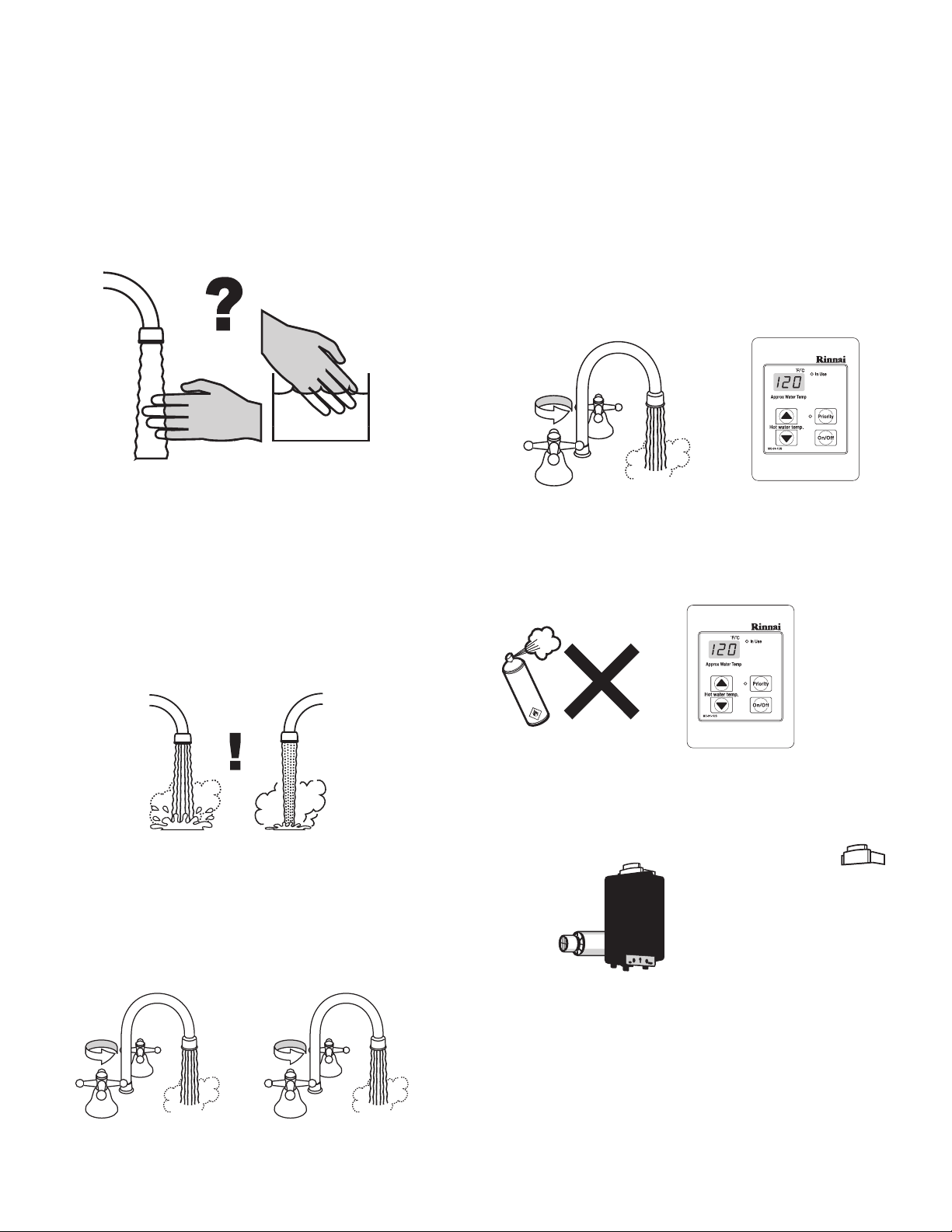
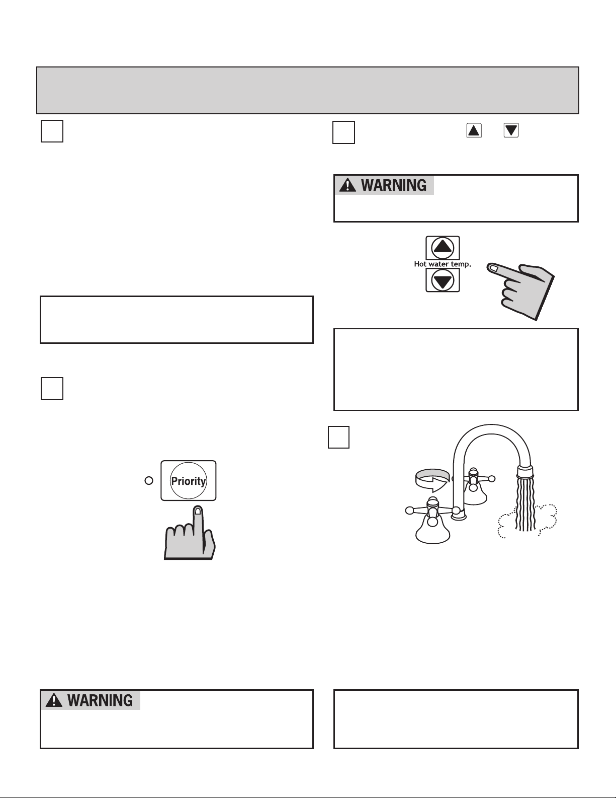
B A S I C O P E R A T I O N
1
Adjusting Temperature
The o utlet wate r tem pera ture of th e Rin nai
Water He ater can o nly b e adj uste d by
the u ser us ing t he re mote cont roll er(s ).
To adju st th e set poin t temp erat ure o f
the R innai Water H eate r, a ll hot wate r
taps must b e clo sed, and a ll ci rcul atin g
pump s turn ed off (whe re ap plic able ). The
temp eratu re di spla yed o n thi s rem ote
cont rolle r wil l als o be d ispl ayed on al l
othe r remo te co ntro ller (s).
NOTE: TEMPERATURE CANNOT BE
ADJUSTED EXCEPT BETWEEN 98°F AND 110
°F WHEN ANY HOT WATER TAP IS OPEN.
To take cont rol o f the Rinna i Water Heat er
2
all h ot wat er ta ps mu st be clos ed. P ress
the " Prior ity b utto n" on the C ontr olle r you
want to set the t empe ratu re wi th, a nd
the g reen " Prio rity " ind icat or li ght w ill
3
Simp ly pre ss th e or butt on
unti l the r equi red t empe ratu re is
disp layed on th e Dig ital Moni tor.
There is a hot water
scald potential if the
thermostat is set to high.
NOTE: CHECK LOCAL CODES FOR
THE MAXIMUM WATER TEMPERATURE
SETTING ALLOWED WHEN USED IN
NURSING HOMES, SCHOOL, DAY CARE
CENTERS, AND ALL OTHER PUBLIC
APPLICATIONS.
4
Rinnai America
glow. This i ndic ates that the R inna i Water
Heat er is r eady to su pply hot w ater at
the s et tem pera ture as so on as a tap is
open ed.
Note : Rinn ai Wate r Hea ter w ill n ot pro vide
hot w ater i nsta ntly at th e hot wate r
xtures. Any cold water existing in the hot
water lines must be purged rst.
CHECK WATER
TEMPERATURE BEFORE
ENTERING SHOWER OR
BATH.
9
To operate t he Ri nnai Water He ater
simp ly tur n any hot w ater tap o n.
This w ill au tomat icall y ligh t the b urner
prov iding hot w ater at th e pre set
temp eratu re. I f the opti onal remo te
cont rolle r(s) have been inst alle d, th e
red “ IN USE ” ind icat or wi ll gl ow on
all r emote cont roll er(s ).
NOTE: If a newly installed unit has not
been powered for at least six hours then
the temperature will return to the default
setting if power is interrupted.
FF Models
Page 10

A B O U T H O T W A T E R
Hot Water I s D ang erou s, espec ial ly for t he youn g an d t he elder ly or
the inrm. The Rinnai Water Heater allows you to precisely control the
temp era ture of yo ur h ot wate r, ensu ring sa fe hot w ate r t empe rat ures .
Water Tempe ratu res o ver 1 25°F can ca use
seve re bur ns in stan tly o r dea th fr om sc alds .
Hot Water can cause rst degree burns with
expo sure f or as litt le as :
3 se cond s at 1 40 °F
20 sec onds at 13 0 °F
8 mi nute s at 120 ° F
Test th e tem pera ture of the wate r wit h you r
elbo w befo re pl acin g a ch ild i n the bath or
show er.
Do not leave a child or an inrm person in
the b ath un supe rvis ed.
BURN
S c a l d s - F i r s t A i d
1) Remove clothing; Remo ve al l wet clot hing , qui ckly. Wet clo thin g ret ains the h eat.
2) Apply cold water for 30 minutes; Imm edia tely subm erge the b urnt area in co ld
wate r for 3 0 min utes to re duce the h eat i n the skin , pre vent ing d eepe r bur ning.
Neve r use b utte r, o ils o r oin tmen t to c over the b urn. T hey m ay re tain the h eat.
3) Keep the scalded person warm; Pl ace a blan ket a roun d the perso n.
4) Seek Medical Advice; Cal l you r med ical advi ce ho tlin e and desc ribe the s cald,
foll ow the ir di rect ions .
Rinnai America
10
FF Models
Page 11
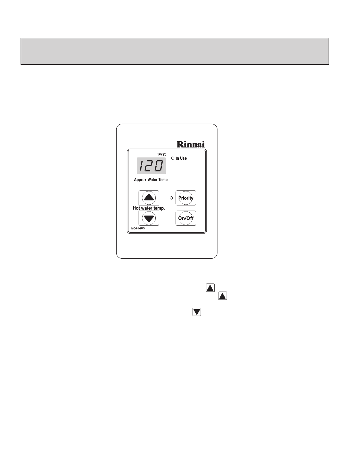
G E N E R A L C O N T R O L L E R I N F O R M A T I O N
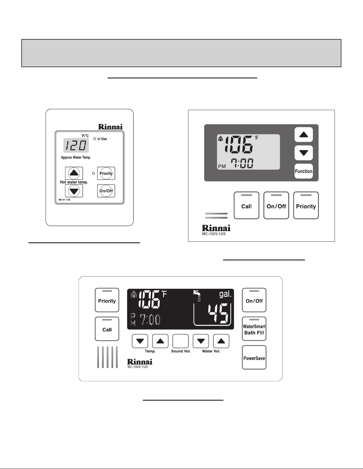
REMOTE CONTROLLERS IDENTIFICATION
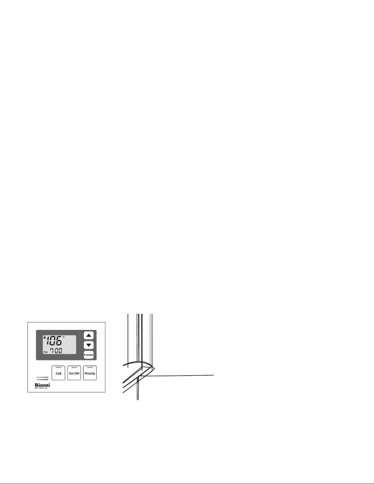
MC-91-1US (comes with the unit)
MC-100V-1US (optional)
BC-100V-1US (optional)
The c ontro ller (s) f or th e Rin nai Wate r Hea ter a llow the c usto mer t o con trol the f unct ions of th e
wate r heat er an d to d iagn ose c erta in fa ult c ondi tion s
Rinnai America
11
FF Models
Page 12
R E M O T E C O N T R O L L E R O P E R A T I O N
DIAGNOSTIC USE OF CONTROLLER
1.
main tenan ce co des, pres s ‘On /Off ’ f ollo wed b y the
2.
for 2 secon ds an d sim ulta neou sly p ress ‘On/ Off’ but ton.
3.
Rinnai America
To Display Maintenance Codes: Pr ess ‘ On/O ff’ butt on. To se quen ce th roug h sto red
ther mosta t but ton.
To Display Water Flow through water heater: Pr ess the rmos tat b utto n, ho ld
To display Outlet Water Temperature: Pres s
12
FF Models
Page 13
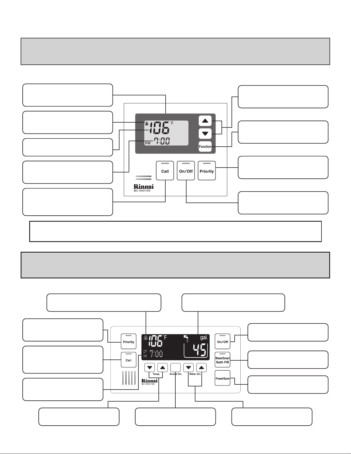
Digital Monitor
Indicates the selected water
temperature. Error messages flash
in the event of a failure.
ON/OFF
Used to switch the water heater on
and off.
Priority
Pressing takes control of the water
temperature by this controller only
when all taps are open.
Function
Enables the user to set the clock
and sound volume functions.
Thermostat
Increases or decreases the desired
water temperature.
In Use Indicator
Indicates that a hot water tap is open
and that control of the temperature is
taken at another controller.
Water Temperature Indicator
Indicates the selected hot water
temperature.
Clock
12 Hour AM / PM clock. In the event
of a fault, codes for error messages
will flash here.
Call
Allows user to contact another
controller. Can be used as a
communication channel for errands
or in emergency situations.
In Use Indicator
Indicates that a hot water tap is open and that control
of the temperature is taken at another controller.
Priority
Pressing takes control of the water
temperature by this controller only
when all taps are off.
Call
Allows user to contact another
controller. Can be used as a
communication channel for errands
or in emergency situations.
Clock
12 Hour AM / PM clock. In the event
of a fault, codes for error messages
will flash here.
Thermostat
Increases or decreases the desired
water temperature.
Sound Volume
Used to select the voice prompt
volume.
Water Smart / Bath Fill Indicator
Used to select Water Smart / Bath Fill Function.
ON/OFF
Used to switch the water heater on
and off.
Water Smart / Bath Fill
Used to select Water Smart / Bath
Fill Function.
Power Save
Indicates that the remote is in the
energy saving mode.
Water Volume
Used to select Water Smart / Bath
Fill volumes.
D E L U X E C O N T R O L L E R
ABOUT THE DELUXE CONTROLLER (MC-100V-1US)
NOTE: With power interruption, water heater will automatically default to the ON position to
provide hot water.
A B O U T T H E TH E D E L U X E B AT H R O O M CO N T R O L L E R (B C - 1 0 0 V- 1 U S )
Rinnai America
D E L U X E B A T H R O O M C O N T R O L L E R
13
FF Models
Page 14
HOTHOT
COLDCOLD
ON!ON!
Page 15
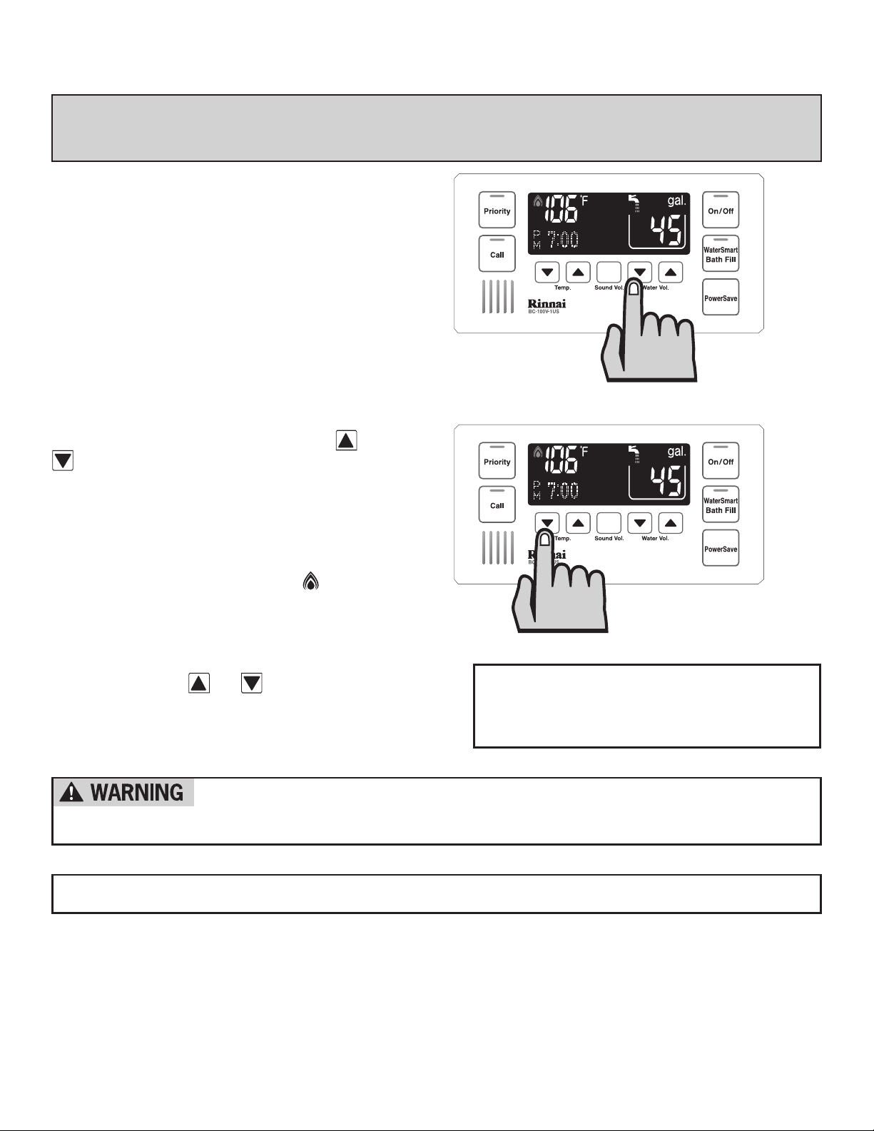
D E L U X E B A T H R O O M C O N T R O L L E R
Setting the Sound Volume
The v oice p romp t sou nd vo lume for a ll De luxe
Cont rolle r(s) can b e set indi vidu ally. To do
this , pres s the ‘Sou nd Vol.’ but ton. T he de faul t
voic e prom pt so und v olum e is m ediu m, ea ch
subs equen t pre ss of the ‘ Soun d Vol.’ will cycle
thro ugh th e ava ilab le vo lume sett ings in th e
foll owing orde r: Hi gh Voice - Off Voice ( beep )
- Off So und ( no be ep) - Low Voice - Med ium
Voice.
Adjusting Temperature
Simp ly pre ss th e ‘Ho t wat er te mp.’ or
butt ons un til t he re quir ed te mper atur e is
disp layed on th e Dig ital Moni tor.
To Oper ate t he ho t wat er uni t, op en an y hot
wate r tap. This w ill a utom atic ally ligh t the
burner providing hot water. The red ame of the
wate r heat er ‘I n Use Indi cato r ’ will illum inat e
on th e Tempera ture Cont roll er.
Once the ho t wat er is runn ing, if th e set
temp eratu re is eith er to o hot or co ld, p ress the
‘hot water temp . or butt ons u ntil the
desi red te mper atur e is r each ed.
CHECK WATER TEMPERATURE BEFORE USE.
A parent should always check the temperature before a child is placed in contact
with hot water.
NOTE: Avoid getting water in the speaker as this may cause damage.
NOTE: TEMPERATURE CANNOT BE
ADJUSTED EXCEPT BETWEEN 98°F
AND 110°F WHEN ANY HOT WATER TAP
IS OPEN.
Rinnai America
15
FF Models
Page 16

Page 17

HOTHOT
COLDCOLD
ON!ON!
HOTHOT
COLD
ON!OFF!
COLD
Page 18

aP
te
S
rellortn
oC
t
)le
d
o
M FF( nret
++
+S
U1-
19-C
M
1
++
SU1-19-C
M+S
U1-
19-C
M
2
+
S
U1-19-
CM+
SU1-19-C
M+S
U1-
19-C
M
3
S
U1-19
-
CM
+S
U1-
19-CM+SU1-19-C
M+
S
U1-
19-
C
M
4
001
-CM +V001-CB
+
+S
U1-
19-C
M
5 V
001
-
CM
+
V
001-C
B+
SU1-
19-
C
M+
S
U1-
19-C
M
6
V
eto
m
e
R exul
eD
dna srel
lor
tn
oC
— — —
— —
—
—
**
led
o
m
04153103152102
1
51
1
01
1
80
1
60
1
401201
0
0
189
5810
61
0
51
0
41
5
31
0
31
5
21
0
21———
———
—————
REU-V2532FFU / REU-V2532FFUD
REU-V2520FFU / REU-V2520FFUD
REU-V2520FFUC / REU-V2520FFUCD
REU-V2532FFUC / REU-V2532FFUCD
(°F)
(°F)
(°F)
5
8106
1
05
1
04
1
53
1
03
1
52
1
02
1
5
1
1
0
1
1
8
0
1
60
1
40120
1
00189
A .xorpp
(°C)erutar
ep
m
et
58
17
66
06
75
45
25
94
64
34
241
4
04938373
erutarepmet
Water Smart / Bath Fill Temperature Table
water smart/
bath fill temperature
02181161141121101180160140120100189
Approx.
temperature
(°F)
(°C)
948
4
746
44
43
4
2414
04
938373
erutarepmet
C O N T R O L L E R S S E T P A T T E R N / T E M P E R A T U R E T A B L E S
Temper atur e con trol lers a llow s pre cise temp erat ure c ontr ol by the u ser. When used corr ectl y,
the hot water unit will deliver the selected temperature, even when the water ow is varied,
or mo re tha n one tap i s in u se. E ach Temp erat ure C ontr olle r can be in divi duall y pro gram med,
howe ver th e wat er he ater unit can o nly d eliv er on e set temp erat ure a t any time. The av aila ble
temp eratu res (OF) ar e as fo llow s:
Temperature Table by Models
Suggested temperatures are:
Kitchen 120OF, Shower 98OF - 110
O
F, Bath ll 102
These temperatures are suggestions only. You may nd higher or lower temperatures more comfort-
able. Maintaining lower temperatures helps save energy. To obtain water temperatures lower than
98OF, simply add cold water.
O
F - 114OF
Deluxe Controllers are an optional extra. ‘Controller’ and ‘Deluxe’ Controllers can be installed togeth-
er. Controllers allow temperature selection only. ‘Deluxe’ Controllers have temperature selection, bath
ll and clock functions.
Cont rolle rs al low t he wa ter t empe ratu re to be se t fro m the vari ous l ocat ions w here they are
inst alled . The t empe ratu re se lect ed wi ll be avai labl e to al l out lets . Bel ow ar e the comb inat ion o f
Cont rolle rs th at ar e offe red b y Rin nai:
Controllers Combination Pattern
**See c ontro ller man ual in con troll er carto n box for mor e infoma tion d etail .
Rinnai America
18
Water Smart / Bath
Fill tem perat ure cann ot
excee d 120 OF for the
follo wing com merci al
model s with no by-p ass:
REU-V 2520F FUC
REU-V 2520F FUCD.
FF Models
Page 19

Error
02
03
10
11
12
Faulty
No burner operation during
freeze protection mode
Power interruption during
Bath fill (Water will not flow
when power returns).
Air Supply or Exhaust
Blockage
No Ignition
Flame Failure
Remedy
Service Call
Turn off all hot water taps. Press ON/OFF twice.
Ensure Rinnai approved venting materials are being used.
Check that nothing is blocking the flue inlet or exhaust.
Check all vent components for proper connections.
Ensure vent length is within limits.
Ensure condensation collar was installed correctly.
Verify dip switches are set properly.
Check fan for blockage.
Check that the gas is turned on at the water heater, gas meter, or cylinder.
Ensure gas type and pressure is correct.
Ensure gas line, meter, and/or regulator is sized properly.
Bleed all air from gas lines.
Verify dip switches are set properly.
Ensure appliance is properly grounded.
Disconnect all MSA controls.
Ensure igniter is operational.
Check igniter wiring harness for damage.
Check gas solenoid valves for open or short circuits.
Remove burner cover and ensure all burners are properly seated.
Remove burner plate and inspect burner surface for condensation or debris.
Check that the gas is turned on at the water heater and gas meter. Check for obstructions in the flue
outlet.
Ensure gas line, meter, and/or regulator is sized properly.
Ensure gas type and pressure is correct.
Bleed all air from gas lines.
Ensure proper Rinnai venting material was installed.
Ensure condensation collar was installed properly.
Ensure vent length is within limits.
Verify dip switches are set properly.
Ensure appliance is properly grounded.
Disconnect keypad.
Disconnect all MSA controls if installed.
Check power supply for loose connections.
Check power supply for proper voltage and voltage drops.
Ensure flame rod wire is connected.
Check flame rod for carbon build-up.
Disconnect and re-connect all wiring harnesses on unit and PC board.
Check all components for electrical short.
Check gas solenoid valves for open or short circuits.
Remove burner plate and inspect burner surface for condensation or debris.
E R R O R M E S S A G E S
The R innai Water H eate r has the a bilit y to c heck its o wn op erat ion c onti nuou sly. I f a fa ult
occurs, an Error Message will ash on the Digital Dispaly of the Remote Controller. This assists
with diagn osin g the faul t, an d may enab le yo u to o verc ome a prob lem w itho ut a se rvic e cal l.
Plea se ide ntif y the code disp laye d whe n inq uiri ng ab out s ervi ce.
Failure to remedy faults may result in severe burns, scalds, and/or
death.
Rinnai America
19
FF Models
Page 20

Error
14
16
32
33
34
52
61
65
71
72
LC
(00)
No
code
Faulty
Thermal Fuse
Over Temperature Warning
Outgoing Water
Temperature Sensor Fault
Heat Exchanger Outgoing
Temperature Sensor Fault
Combustion Air Temperature
Sensor Fault
Modulating Solenoid Valve
Signal Abnormal
Combustion Fan Failure
Water Flow Servo Faulty
(Does not stop flow properly)
SV0, SV1, SV2, and SV3
Solenoid Valve Circuit Fault
Flame Sensing Device Fault
Scale Build-up in Heat
Exchanger (when checking
maintenance code history
“00” is substituted for “LC” )
Nothing happens when
water flow is activated.
Remedy
Check gas type of unit and ensure it matches gas type being used.
Check for restrictions in air flow around unit and vent terminal.
Check for low water flow in a circulating system causing short-cycling.
Ensure dip switches are set to the proper position.
Check for foreign materials in combustion chamber and/or exhaust piping.
Check heat exchanger for cracks and/or separations.
Check heat exchanger surface for hot spots which indicate blockage due to scale build up. Refer to
instructions in manual for flushing heat exchanger.
Measure resistance of safety circuit.
Ensure high fire and low fire manifold pressure is correct.
Check for improper conversion of product.
Check for restrictions in air flow around unit and vent terminal.
Check for low water flow in a circulating system causing short-cycling.
Check for foreign materials in combustion chamber and/or exhaust piping.
Check for clogged heat exchanger.
Check sensor wiring for damage.
Measure resistance of sensor.
Clean sensor of scale build up.
Replace sensor.
Check sensor wiring for damage.
Measure resistance of sensor.
Clean sensor of scale build up.
Replace sensor.
Check for restrictions in air flow around unit and vent terminal.
Check sensor wiring for damage.
Measure resistance of sensor.
Clean sensor of scale build up.
Ensure fan blade is tight on motor shaft and is in good condition.
Replace sensor.
Check modulating gas solenoid valve wiring harness for loose or damage terminals.
Measure resistance of valve coil.
Ensure fan will turn freely.
Check wiring harness to motor for damaged and/or loose connections.
Measure resistance of motor winding.
Water Flow Servo or wiring faulty. Check Water Flow Servo wiring harness connection.
Measure resistance of Water Flow Servo wiring.
If blank screen is present on remote control then the Water Flow Servo has shorted out. Unplug Water
Flow Servo. If remote lights up and unit starts operating then replace Water Flow Servo.
Check wiring harness to all solenoids for damage and/or loose connections.
Measure resistance of each solenoid valve coil.
Ensure flame rod is touching flame when unit fires.
Check all wiring to flame rod for damage.
Remove flame rod and check for carbon build-up; clean with sand paper.
Check inside burner chamber for any foreign material blocking flame at flame rod.
Measure micro amp output of sensor circuit with flame present.
Replace flame rod.
Flush heat exchanger. Refer to instructions in manual.
Replace heat exchanger.
Clean inlet water supply filter.
On new installations ensure hot and cold water lines are not reversed.
Check for bleed over. Isolate unit from building by turning off hot water line to building. Isolate the
circulating system if present. Open your pressure relief valve; if unit fires, there is bleed over in your
plumbing.
Ensure you have at least the minimum flow rate required to fire unit.
Ensure turbine spins freely.
Measure the resistance of the water flow control sensor.
Remote control does not light up but you have 12 VDC at the terminals for controls.
E R R O R M E S S A G E S
Rinnai America
20
FF Models
Page 21

M A I N T E N A N C E & S E R V I C E I N F O R M A T I O N
Always turn off the electrical power supply, the manual gas valve and
the manual water control valve whenever servicing the unit.
The Rin nai Wat er Hea ter sh ould be chec ked by a Prope rly Tra ined
Technic ian o nce a year. A Pro perl y Trai ned R inna i Techni cian
shou ld per form any r epai rs th at ma y be n eces sary.
The f ollow ing i tems shou ld be chec ked e ach i nspe ctio n:
1) The area arou nd the Rinn ai un it sh ould be fr ee fr om co mbus tibl e mat eria ls
such as clo th, v eget atio n and buil ding mate rial s. (s ee pa ge 8)
2) Che ck bu rner s for p rese nce o f for eign debr is, i nsec ts or bugs . These item s
are n ot cov ered by th e uni t’s wa rran ty.
3) Remove and clean the inlet water lter.
Keep t he app lianc e area clear and fr ee fro m comb usti ble ma teria ls, ga solin e,
4)
and other ammable vapors and liquids.
5) Do not obstruct ow of combustion and ventilation air.
In the case of any fault or error message from the Rinnai Water Heater,
rst turn all hot water taps off. Wait for 5 seconds. Turn the hot water tap back
on. I f the e rror mess age s t il l re ma in s , cal l y ou r Ri nn ai A u th or i ze d Se rv ic e
Re pr e se nt at i ve o r Ri nn ai a t 8 00 -6 2 1- 94 19 .
Should overheating occur or the gas supply fail to shutoff, turn off th e man ual
gas c ontro l val ve to the a ppli ance .
DO NO T ATTEMPT TO SER VICE Y OUR R inna i YOUR SELF.
Call a Rinnai Authorized Service Technician or call your installer.
Rinnai America
21
FF Models
Page 22

M A I N T E N A N C E & S E R V I C E I N F O R M A T I O N
MAINTENANCE SUGGESTIONS
This water heat er ha s bee n des igne d and cons truc ted
for a long p erfo rman ce li fe wh en in stal led a nd op erat ed
prop erly u nder norm al co ndit ions . Reg ular insp ecti ons,
as ou tline d in t his s ecti on, a re st rong ly re comm ende d
as a means of keeping your heater operating efciently.
Cons idera tion shou ld be give n to p erio dic m aint enan ce
of sc ale re mova l in a ppli cati ons w here the w ater
hard ness q uali ty is elev ated and t he wa ter h eate r
runs for ex tend ed pe riod s suc h as i n com merc ial
appl icati ons o r app lica tion s wit h cir cula ting loop s.
1. Cle ani ng
The w ater h eate r sho uld b e cle aned annu ally.
Keep the wa ter h eate r cle ar of dust and d ebri s
espe ciall y in a nd ar ound burn er.
Clea ning p roce dure s for the R inna i Water H eate r
are a s foll ows:
1) Turn o ff and disco nnec t ele ctri cal p ower. Al low
to co ol for one h our.
2) Rem ove t he Fr ont Pa nel b y rem ovin g scr ews.
See p arts b reak down on pa nels .
3) Use pres suri zed ai r to r emov e dus t fro m aro und
main burne r.
4) Use soft dry c loth t o wip e cab inet .
DO N OT D AMAG E O R D ISTORT ANY PARTS
OF H EATER.
DO N OT U SE WET CL OTH OR SPRAY
CLEA NER S ON BU RNE R.
2. Visual check of main burner ames.
The burner must ame evenly over the entire
surface when operating correctly. The ame must
burn with a clear, blue, stable ame. See the parts
brea kdown of th e bur ner f or th e loc atio n of v iew
port s. An y and all p arts remo ved f or in spec tion or
serv ice mu st be repl aced befo re op erat ing t he un it.
* VENT MAINTENANCE
* VE NT S YSTE M
Must be che cked annu ally for
bloc kage o r det erio rati on. S ee
vent insta llat ion i nstr ucti ons.
* MA INT ENAN CE- ELEC TRI C
MOTOR S
Moto rs are perm anen tly
lubr icate d and need no
lubri cati on. Ke ep fa n and m otor
free of dus t and dirt , cle an
annu ally.
The ame pattern should be as shown in the
foll owing Figu res.
Rinnai America
22
FF Models
Page 23

TR O U B L E S H O O T IN G A N D C O M M O N Q U E S TI O N S
- I don't have any hot water when I open the tap!
Q
- Mak e sure ther e is g as, w ater and e lect rici ty to the R inna i Water H eate r
A
(the power is tu rned on an d the gas i s tur ned o n)
- When I was using the hot water, the water got cold!
Q
- If you adjusted the ow from the tap to lessen it, you may have gone below the minimum
A
ow required. The Rinnai Water Heater requires a minimum ow rate to operate (see
specication page for ow rate of your unit). If you mix the water with a tap and attempt
to ge t a tem pera ture well belo w the temp erat ure b eing cont roll ed by the u nit, i t may drop
the ow below the desired minimum ow rate. Decrease the temperature supplied by the
Rinnai Water Heater at the remote control or increase your total ow.
- White smoke comes out of the exhaust!
Q
- Dur ing co lder weat her w hen t he ex haus t tem pera ture is ho tter than the a ir, t he ex haus t
A
fume s cond ense prod ucin g whi te st eam.
- When I open a hot tap. I do not immediately get hot water!
Q
- Hot water must trav el th roug h you r plu mbin g fro m the Rinn ai Water Heat er to the f auce t.
A
The time period for hot water to reach your xture is determined by the amount of water in
your plumbing system between your water heater and the xture, water pressure, ow rate
of xture in use, etc.
- After I turn off the hot water tap, the fan on the Rinnai Water Heaters continues to run!
Q
- The fan is designed to be on for 65 seconds after the ow of water stops.This is to ensure
A
cons tant w ater temp erat ures duri ng ra pid s tart ing a nd st oppi ng, a s wel l as ex haus ting any
residual gas ue products from the unit.
F O R Y O U R S A F E T Y R E A D B E F O R E O P E R AT I N G
If you do not follow these instructions
exactly, a fire or explosion may result causing property
damage, personal injury or loss of life.
A. This appliance does not have a pilot. It is
equipped with a direct ignition device which
automatically lights the burner. Do no t try to
ligh t the b urne r by h and.
B. BEFORE OPERATING: Smell all around the
appliance area for gas. Be sure to smell next
to the oor because some gas is heavier
than air and will settle on the oor.
WHAT TO DO IF YOU SMELL GAS
Do no t try t o lig ht an y app lian ce.
•
Do not t ouch any e lect ric s witc h, do not
•
use a ny pho ne in your buil ding .
Im medi atel y cal l you r gas supp lier from a
•
neig hbor ’s p hone . Fol low t he gas supp lier ’s
inst ructi ons.
If yo u cann ot re ach y our g as su ppli er, call
•
the re department.
C. Use o nly you r hand to oper ate re mote co ntrol
keyp ad. Ne ver u se to ols. If th e rem ote
keyp ad doe sn’t work , do n ot tr y to r epai r
it, call a qualied service technician. Force
or attempted repair may result in a re or
expl osion .
D. Do not us e thi s app lian ce if any p art h as
been under wate r. I mmed iate ly ca ll a
qualied service technician to inspect the
appl iance and t o rep lace any p art o f the
cont rol sy stem and a ny ga s con trol whic h
has b een un der w ater.
Rinnai America
23
FF Models
Page 24

O P E R A T I N G I N S T R U C T I O N S
1) STOP! R ead t he sa fety info rmat ion a bove
befo re pro ceed ing.
2) Set t he the rmos tat t o low est s etti ng.3 )
Turn off all electric power to the appliance.
4) This appliance does not have a pilot. It is
equipped with a direct ignition device which
automatically lights the burner. Do no t try to
ligh t the b urne r by h and.
5) Turn the manu al va lve l ocat ed at gas
inle t of th e app lian ce cl ockw ise
inle t of ap plia nce c ount ercl ockw ise
to “O N”.
8) Turn on a ll el ectr ic po wer t o the
appl iance .
9) Set t hermo stat to de sire d set ting .
10) If the a ppli ance will not o pera te,
Foll ow the inst ruct ions “To Turn Off
Gas To Ap plia nce” and c all y our
serv ice te chni cian or ga s sup plie r.
Close d manual v alve
ß
(“OFF ” positi on)
Open Man ual valv e
(“ON” p ositi on)
To Turn Off Gas To A ppl ian ce
1) Se t the t herm osta t to l owes t set ting .
2) Turn o ff all elect ric p ower to th e app lian ce if serv ice i s to b e per form ed.
®
3) Turn t he ma nual valv e at g as in let of appl ianc e clo ckwi se
to “O FF”
Rinnai America
24
FF Models
Page 25

Installer’s Instructions
This section is for the Qualified Installer
only. If you are not properly trained,
you should not install this unit. The
warranty may be voided due to installation
by a non-qualied installer. For information
on Rinnai Training Courses, call
1-800-621-9419.
Warnings .. .... ..... ..... ..... ..... ..... ..... ..... .... ..... ..... ..... ..... . 26, 27
Locat ing the Vent Termin al ..... ..... .... ..... ..... ..... ..... ..... .... 28
Perfo rmanc e Data ... ..... ..... ..... ..... ..... ..... ..... .... ..... ..... ..... 2 9
Dimen sions ..... ..... .... ..... ..... ..... ..... ..... ..... ..... .... ..... ..... .... 30
Recom mende d Piping f or Inst allat ion . ..... ..... . 31,32 ,33,3 4
Venting ..... ..... .... ..... ..... ..... ..... ..... ..... ..... ..... .... ..... ..... . 35,3 6
Contents
of Installer’s
Manual
Freez e Protec tion ..... ..... ..... ..... ..... .... ..... ..... ..... ..... ..... ... 37
Gas Pipi ng Sizin g Chart ..... ..... ..... ..... .... ..... ..... ..... ..... ... 38
Gas Pipi ng Notes ........ ..... ..... .... ..... ..... ..... ..... ..... ..... ..... 3 9
Water Pipin g Notes. ..... ..... ..... .... ..... ..... ..... ..... ..... ..... ..... 4 0
Press ure Reli ef Valve . ..... ..... ..... ..... ..... .... ..... ..... ..... ..... . 40
Light ing the Uni t .......... ..... ..... ..... .... ..... ..... ..... ..... ..... ..... 4 1
Remot e Contro llers .. ..... ..... ..... ..... ..... ..... .... ..... ..... ..... .... 42
Remot e Contro llers I nstal lati on ..... ..... .... ..... ..... ..... .. 43 ,44
Testin g ....... ..... ..... .... ..... ..... ..... ..... ..... ..... ..... .... ..... ..... .... 45
Schem atic Dia gram .. ..... ..... ..... ..... .... ..... ..... ..... ..... ... 4 6,47
Rinnai America
www.rinnai.us
800-621-9419
25
FF Models
Page 26

I N S T A L L E R ’ S I N S TA L L A T I O N I N S T R U C T I O N S
-Warnings- (Residential Unit)
This manual must be followed exactly.
1) Re ad the safe ty is sues comp lete ly be fore inst alli ng th e Rin nai Wate r Hea ter.
2) This wate r hea ter i s sui tabl e for resi dent ial w ater (pota ble) heat ing O NLY.
DO NO T use th is wa ter h eate r for spac e hea ting , com bina tion s pace heat ing/
dome stic w ater heat ing, or co mmer cial wate r hea ting appl icat ions .
3) The Rinn ai Water Heat er is not s uita ble f or use in po ol or spa a ppli cati ons.
4) Thi s uni t is d esign ed to be in stal led i ndoo rs us ing t he pr oper vent pipi ng to
exha ust by -pro duct s of c ombu stio n to t he ou tsid e env iron ment . Con tact your
deal er or R inna i for prop er ve nt ki ts. DO NOT oper ate t his u nit wi thou t ven t
pipi ng con nect ed. E xhau st ga sses must be ex pell ed ou tsid e the home .
5) Mai ntai n pro per sp ace a roun d the unit for p rope r ser vici ng an d ope rati on.
Mini mum cl eara nces from comb usti ble m ater ials are l iste d bel ow.
To p of H eate r 6 inch es
Back of Hea ter 0 inch
Fron t of He ater 6 inch es
Side s of He ater 2 inc hes
Floo r 12 inc hes
Vent/Air Inta ke 0 i nche s
6) Ins tall er mu st ins tall a Pre ssur e rel ief v alve . Pip e pre ssur e rel ief d isch arge to a
drai n or ou tsid e env iron ment (See pres sure reli ef va lve s ecti on).
7) Th e appl ianc e sho uld b e loc ated in an area wher e lea kage of th e uni t or
conn ectio ns wi ll no t res ult i n dam age t o the area adja cent to th e app lian ce or
to lower oors of the structure. When such locations cannot be avoided, it is
reco mmend ed th at a s uita ble d rain pan, adeq uate ly dr aine d, be inst alle d unde r
the appliance. The pan must not restrict combustion air ow.
Rinnai America
26
FF Models
Page 27

I N S T A L L E R ’ S I N S TA L L A T I O N I N S T R U C T I O N S
-Warnings- (Commercial Unit)
This manual must be followed exactly.
1) Re ad the safe ty is sues comp lete ly be fore inst alli ng th e Rin nai Wate r Hea ter.
2) This wate r hea ter i s sui tabl e for wate r (po tabl e) he ating or sp ace h eati ng.
- The pi ping and c ompo nent s con nect ed to the R innai Water H eate r mus t app roved
for u se in p orta ble w ater syst ems.
- To xic c hemi cals s uch a s tho se us ed fo r boi ler w ater trea tmen t are NOT to b e
intr oduce d to t he po rtab le wa ter u sed f or sp ace h eati ng.
- The Ri nnai Water He ater, if i t wil l be u sed a s a po tabl e wat er so urce , mus t not be
conn ected to a s yste m tha t was prev ious ly us ed wi th a n onpo tabl e
wate r heat ing a ppli ance .
- When t he sy stem requ ires wate r for spac e hea ting a t tem pera ture s hig her
than requi red f or ot her u ses, a mea ns su ch as mixi ng va lve s hall be in stal led to
temp er the wate r for othe r use s in o rder to re duce the s cald haza rd po tent ial.
3) Th e Rinn ai Wate r Hea ter i s not suita ble f or us e in p ool o r spa appl icat ions
4) Thi s uni t is d esign ed to be in stal led i ndoo rs us ing t he pr oper vent pipi ng to
exha ust by -pro duct s of c ombu stio n to t he ou tsid e env iron ment . Con tact your
deal er or R inna i for prop er ve nt ki ts. DO NOT oper ate t his u nit wi thou t ven t pip ing
conn ected . Exh aust gass es mu st be expe lled outs ide t he ho me.
5) Mai ntai n pro per sp ace a roun d the unit for p rope r ser vici ng an d ope rati on.
Mini mum cl eara nces from comb usti ble m ater ials are l iste d bel ow.
6) Ins tall er mu st ins tall a Pre ssur e rel ief
Top of H eate r 6 inches
valv e. Pip e pre ssur e rel ief d isch arge
Back of He ater 0 inc h
to a d rain o r out side envi ronm ent ( See
Fron t of H eate r 6 inche s
pres sure r elie f val ve se ctio n).
Side s of H eate r 2 inc hes
Floo r 12 inches
Vent/Air Inta ke 0 inc hes
7) Th e appl ianc e sho uld b e loc ated in an area wher e lea kage of th e uni t or
conn ectio ns wi ll no t res ult i n dam age t o the area adja cent to th e app lian ce or
to lower oors of the structure. When such locations cannot be avoided, it is
reco mmend ed th at a s uita ble d rain pan, adeq uate ly dr aine d, be inst alle d unde r
the a pplia nce.
Rinnai America
27
FF Models
Page 28

Page 29

0.0
0.5
0.
01
0
.51
0.02
0.52
0.03
9
8
7
6
5
4
32
10
)
m
pg( wolF reta
W
Pressure Loss (psi)
0.0
0.01
0
.02
0
.0
3
0
.04
0
.05
0
.06
Pressure Loss (ft head)
V2532FFU/FFUC
V2532FFUD/FFUCD
V2520FFU/FFUC
V2520FFUD/FFUCD
Page 30

Page 31

G
a
s
S
u
p
p
l
y
3
/
4"C
o
l
d
W
a
t
e
r
S
u
p
p
l
y
L
i
n
e
3/4" Hot Water Supply Line
Rinnai
Water Heater
Rinnai
Equipment List
(Residential and
Commercial)
Rinnai
Water Heaters
(Indoor)
MC-91 Controller
(Included)
MC-100V a
Page 32

103 International Drive
Peachtree City, Georgia 30269
RINNAI WATER HEATERS
Domes
tic Hot Water - Circulation Systems
1 Rinnai
Water Heater with Electric Storage Tank
This is not an engineered drawing, it is intended only as a guide and
no
t as a replacement for professionally engineered project drawings.
This drawing is not intended to describe a complete system, it is up
to the contractor/engineer to determine the necessary components
for and configuration of the particular system being installed. The
drawing does not imply compliance with local building code
requirements. It is the engineer/contractor responsiblity to ensure
the installation is in accordance with all local building codes. Confer
with
local building officials before installation.
Pressure Relief Valve
3/4" Ball Valve
3/4" Union
Check Valve
S
Pressure Regulator
Cir
culating Pump
Solenoid Valve
Boiler Drain Valve
KEY
Minimum 3/4" Cold Water Supply Line
2-5 Gallon
Electric Water
Heate
r
120°F
Building
Fixtures
Building Return (Not required to be 3/4" Line)
Build
ing Supply
E
x
p
a
n
s
i
o
n
T
a
n
k
G
a
s
S
u
p
p
l
y
QTY
1
1
1
Rinnai
Water Heater
Pump Should be Controlled by an
Aquastat, Timer or Combination
Aquastat and Timer. Pump to be sized
for Pressure Drop through Building
Supply and Return Piping. Pump to be
of Bronze or Stainless Construction.
Notes:
PLEASE NOTE FOR RESIDENTIAL
APPLICATIONS, THIS PIPING
ARRANGEMENT
MAINTAINS FULL
WARRANTY
:
10 Years On Heat Exchanger
5 Years On Parts
Commercial
Application Warranty:
5 Years On Heat Exchanger
5 Years On Parts
Rinnai
Equipment List
(Residential and
Commercial)
Rinnai
Water Heaters
(Indoor)
MC-91 Controller
(Included)
MC-100V and BC-100V
Controllers Optional
RIK-KIT (Optional)
(3/4" Fittings Include:
2 Unions, 2 Ball Valves,
2 Drain Valves and
1 Pressure Relief Valve.)
3
/
4
"
G
a
s
C
o
n
n
e
c
tio
n
Important:
Install building return
line to the hot supply as close as
possible to the Rinnai Water
Heater.
V
e
n
t
i
n
g
E
q
u
i
p
m
e
n
t
L
i
s
t
(
C
o
m
m
e
r
c
i
a
l
a
n
d
R
e
s
i
d
e
n
t
i
a
l
)
I
n
d
oor
U
n
i
t
P
l
e
a
s
e
R
e
v
i
e
w
V
e
n
t
i
n
g
I
n
s
t
r
u
c
t
ion
s
/
G
u
i
d
e
l
i
n
e
s
f
o
r
P
r
o
p
e
r
C
o
m
p
o
n
e
n
t
s
a
n
d
I
n
s
t
a
l
latio
n
.
I N S T A L L E R ’ S I N S TA L L A T I O N I N S T R U C T I O N S
RECOMMENDED PIPING FOR CIRCULATION SYSTEMS
Rinnai America
32
FF Models
Page 33

103 International Drive
Peachtree City, Georgia 30269
RINNAI WATER HEATERS
Domestic Hot Water with Circulation
1 Rinnai Water Heater
This is not an engineered drawing, it is intended only as a guide and
no
t as a replacement for professionally engineered project drawings.
This drawing is not intended to describe a complete system, it is up
to the contractor/engineer to determine the necessary components
for and configuration of the particular system being installed. The
drawing does not imply compliance with local building code
requirements. It is the engineer/contractor responsiblity to ensure
the installation is in accordance with all local building codes. Confer
with
local building officials before installation.
Pressure Relief Valve
3/4" Ball Valve
3/4" Union
Check Valve
S
Pressure Regulator
Circulating Pump
Solenoid Valve
Boiler Drain Valve
KEY
Minimum 3/4" Hot Water
Supply Line
B
u
ild
i
n
g
F
i
x
t
u
r
e
O
u
tle
t
s
(Optional)
2-6 Gallon
Storage Tank
(To eliminate cold water
sandwich effect caused by
frequent On/Off operation)
Pump Should be Controlled by an
Aquastat, Timer or Combination
Aquastat and Timer
Pump to be sized for 3.0 gpm flow @ 12 feet head. Flow Balancing
Valve to be adjusted to 3 GPM flow through water heater with no hot
water taps open. Pump to be of Bronze or Stainless Construction.
Cold Water Supply and Circulation Return Lines Must Be 3/4"
Tubing Throughout Circulation Loop.
Note:
Water heater outlet temperature
cannot be adjusted when
circulation pump is running.
QTY
1
1
1
E
x
p
a
n
s
i
o
n
T
a
n
k
Rinnai
Water Heater
Note:
PLEASE NOTE FOR RESIDENTIAL
APPLICATIONS, THIS PIPING
ARRANGEMENT REDUCES
WARRANTY TO THE FOLLOWING:
3 Years On Heat Exchanger
3 Years On Parts
Rinnai
Equipment List
(Residential and
Commercial)
Rinnai
Water Heaters
(Indoor)
MC-91 Controller
(Included)
MC-100V and BC-100V
Controllers Optional
RIK-KIT (Optional)
(3/4" Fittings Include:
2 Unions, 2 Ball Valves,
2 Drain Valves and
1 Pressure Relief Valve.)
3
/
4
"
G
a
s
C
o
n
n
e
c
t
i
o
n
Commercial Application Warranty:
5 Years On Heat Exchanger
5 Years On Parts
G
a
s
S
u
p
p
l
y
Ven
t
i
n
g
E
q
u
i
p
m
e
n
t
L
i
s
t
(Residential and
I
n
d
o
o
r
U
n
i
t
P
l
e
a
s
e
R
e
v
i
e
w
V
e
n
tin
g
I
n
s
t
r
u
c
tio
n
s
/
G
uid
eli
n
e
s
f
o
r
P
r
o
p
e
r
C
o
mpo
n
e
n
t
s
a
n
d
I
n
s
t
a
l
latio
n
.
Commercial)
I N S T A L L E R ’ S I N S TA L L A T I O N I N S T R U C T I O N S
OPTIONAL PIPING FOR CIRCULATION SYSTEMS
Rinnai America
33
FF Models
Page 34

Rinnai
Water Heater
103 International Drive
Peachtree City, Georgia 30269
RINNAI WATER HEATERS
Domestic Hot Water - Scale Flush Procedure
1 Rinnai Water Heater
This is not an engineered drawing, it is intended only as a guide and
not as a replacement for professionally engineered project drawings.
This drawing is not intended to describe a complete system, it is up
to the contractor/engineer to determine the necessary components
for and configuration of the particular system being installed. The
drawing does not imply compliance with local building code
requirements. It is the engineer/contractor responsiblity to ensure
the installation is in accordance with all local building codes. Confer
with local building officials before installation.
Pressure Relief Valve
3/4" Ball Valv
e
3/4" Union
Check Valve
S
Pressure Regulator
Circulating Pump
Solenoid Valve
Boiler Drain Valve
KEY
G
a
s
S
u
p
p
l
y
RINNAI Water Heater Flush Procedure
1. Disconnect power to the Rinnai Water Heaters.
2. Close valves V3 and V4.
3. Connect pump outlet hose H1 to service valve V2.
4. Connect drain hose H3 to valve V1.
5. Pour approximately 4 gallons of virgin, food grade,
white vinegar (or virgin, food grade, citric acid) into pail.
6. Place free ends of hose H2 and H3 into pail.
7. Open valves V1 and V2.
8. Turn on power to circulating pump and allow solution
to circulate through water heater for 45 minutes.
9. Turn off power to circulating pump.
10. Remove free end of hose H3 from pail.
11. Close valve V2 and open valve V4, only.
Do NOT open valve V3 at this time.
12. Allow water to flow out of hose H3 for 5 minutes,
rinsing cleaning solution from water heater.
13. Close valve V1 and open valve V3.
14. Disconnect hoses H1 and H3 from service valves.
15
. Remove in-line filter from water heater cold water inlet
and clean out any residue. Place filter back into unit.
16. Restore power to water heater.
V1
V3
V2
V4
H1
H2
H3
Circulating Pump
5 gallon pail of virgin, food
grade, white vinegar (or virgin,
food grade, citric acid).
C
o
l
d
W
a
t
e
r
L
i
n
e
H
otW
a
t
e
r
L
i
n
e
n
-
l
i
n
e
F
i
l
t
e
r
I
I N S T A L L E R ’ S I N S TA L L A T I O N I N S T R U C T I O N S
RECOMMENDED SCALE FLUSH PROCEDURE
Rinnai America
34
FF Models
Page 35

Hori zontal Venting with a
Condensate Collector
Hori zontal Venting without a
Condensate Collector
Condensate
Trap
Vertical Venting
(cond ensat e collect or requir ed)
Maximum Height
5 feet
3 in
min
3 in
min
3 in
min
Region s of co ld cli mate w ill cr eate
more con densa te in the ven t
system . A conden sate collector is
recomm ended i n cold cli mates .
If mor e tha n one elbow is used
in the vertica l sect ion y ou mus t
use a c onden sate c ollec tor.
I N S T A L L E R ’ S I N S TA L L A T I O N I N S T R U C T I O N S
Venting
Condensate
Cond ensat e for mati on ca n occ ur in Cate gory III d irec t ven t app lian ces.
Vertical term inati ons m ust i ncor pora te a c onde nsat e dra in an d tra p as c lose as po ssibl e to
•
the a pplia nce.
T he co nden sate trap must cont ain a mini mum of 3" of wate r.
•
Disp ose of cond ensa te pe r loc al co des.
•
Slop e hori zont al ve ntin g 1/4 inch per f oot e ithe r tow ards the h eate r wit h a con dens ate
•
coll ector or to ward s the exha ust t ermi nal.
NOTE: Provisions must be made to prevent the condensate from entering the water heater.
Without proper drainage or disposal condensate will damage the heat exchanger.
Rinnai America
35
FF Models
Page 36

I N S T A L L E R ’ S I N S TA L L A T I O N I N S T R U C T I O N S
Two 45 elbows are considered equivalent to one 90° elbow.
Include termination elbows when using this table.
(1) If the length is less than 22' then move dip switch no. 1 (SW 1) to ON
(2) If the length is less than 16' then move dip switch no. 1 (SW 1) to ON
(3) If the length is less than 10' then move dip switch no. 1 (SW 1) to ON
Number of 90° Elbows
3
23
4
17
5
11
6
5
2
29 (3)
1
35 (2)
0
41 (1)
Venting
Air Intake and Exhaust Vent Pipe Length
Dete rmine the n umbe r of e lbow s in t he ve nt sy stem . The c orres pond ing n umbe r fro m the tabl e
indi cates the m axim um le ngth of ve nt pi pe.
For h igh al titu de in stal lati ons c onta ct Ri nnai at 1- 800- 621- 9419 .
Table 1 Maximum Vent Length (feet)
If it is necessary to adjust the dip switch, ensure that no other dip switches are
changed. Unauthorized adjustments can cause property damage, personal
injury, scalding, or death.
Intake/Exhaust Guidelines
T his w ater heat er is a dir ect v ent w ater heate r and ther efor e is c erti fied and l iste d wit h the
•
vent syste m. The only vent /air inta ke sy stem list ed fo r use w ith t his a ppli ance is th e Rin nai /
Ubbi nk ven t sys tem o r the Heat -Fab Saf- T Vent SC sy stem .
Mini mum wa ll th ickn ess i s 4”. Maxi mum w all t hick ness is 20 ”.
•
Do no t comb ine v ent c ompo nent s fro m diff eren t man ufac turer s.
•
T he ve nt sy stem must vent dire ctly to th e outs ide o f the buil ding and u se ou tsid e air for
•
comb ustio n.
Befo re ins tall atio n, in spec t eac h ven t com pone nt fo r dam age a nd co rrec t seal plac emen t. Do
•
not a ttemp t to f ix or inst all a ny da mage d ven t com pone nts.
Ever y vent conn ecti on mu st be acce ssib le fo r ins pect ion, clea ning , and repla ceme nt.
•
Avoid dips or sa gs in hori zont al ve nt ru ns by inst allin g sup port s per the v ent m anuf actu rers ’
•
inst ructi ons.
Supp ort ho rizo ntal air i ntak e run s eve ry fo ur fe et an d all vert ical air i ntake runs ever y six
•
feet or in a ccor danc e wit h loc al co des.
Venting s houl d be as dire ct as poss ible with a min imum numb er of pipe fitt ings .
•
Vent diam eter must n ot be redu ced.
•
Do no t conn ect t he ve ntin g sys tem w ith a n exi stin g ven t or c himn ey.
•
Do no t comm on ve nt wi th th e ven t pip e of a ny ot her w ater heat er or appl ianc e.
•
Vent conn ecti ons mu st be firm ly pr esse d tog ethe r so t hat t he ga sket s for m an a ir ti ght se al.
•
Refe r to th e ven t pip e man ufac ture rs’ inst ruct ions for c ompo nent asse mbly inst ruct ions .
•
T he fi rst v ent c ompo nent to th e app lian ce mus t be a n app lian ce ad apte r. Th is wi ll pr event
•
addi tiona l com pone nts f rom b eing inst alle d bac kwar ds.
Rinnai America
36
FF Models
Page 37

Filter
Drain
Gas
Valve
GasColdHot
Turn Water Off
Turn Gas Off
Drain Water
Valve
Water
I N S T A L L E R ’ S I N S TA L L A T I O N I N S T R U C T I O N S
Free ze Pro tect ion
If th e Rinn ai wa ter h eate r is d isco nnec ted f rom
eith er the elec tric al su pply or ga s sup ply, or if
ther e is an erro r tha t pre vent s the wate r hea ter f rom
func tioni ng no rmal ly, t here is NO FREE ZE
PROT ECTIO N. Fr eeze prot ecti on of the w ater
heat er is o nly p ossi ble w hen e lect rici ty, g as
supp ly and norm al wa ter h eate r fun ctio ns ar e
enab led. I f you expe ct fr eezi ng co ndit ions whil e
eith er ele ctri city or ga s sup ply i s int erru pted ,
wate r must be co mple tely drai ned f rom w ater
heat er.
This water heat er an d ven ting syst em is
desi gned t o wit hsta nd te mper atur es to as
low a s -30OF, so lo ng as elec tric ity a nd ga s
are s uppli ed to the p rodu ct an d nor mal
wate r heat er fu ncti ons a re en able d. If eith er
gas o r elec tric ity i s int erru pted NO FR EEZE
PROT ECTIO N is a vail able .
The i nstal lati on of auto drai n dow n sol enoi d val ves i s opt iona l. Ho weve r, Ri nnai stro ngly
reco mmend s tha t the se va lves be in stal led t o pre vent dama ge fr om fr eezi ng in c ase t he no rmal
free ze pro tect ion s houl d bec ome d isab led. If th e val ves a re no t ins tall ed the n any prod uct
dama ge due to fr eezi ng wi ll no t be c over ed by the w arra nty.
NOTE: Rinnai is continually updating and improving products, therefore, specications are subject
to change without prior notice. Local, state, provincial and federal codes must be adhered to prior
to installation.
Climate conditions can dictate special applications. Please refer to local codes before installing
product.
Rinnai America
37
FF Models
Page 38

I N S T A L L E R ’ S I N S TA L L A T I O N I N S T R U C T I O N S
Gas Piping Sizing Chart
Capacity Table for Natural Gas
cubic feet / hour
(table assumes .3 inch pressure drop, specic gravity of .60)
Nominal Length of Pipe in Feet
Iron Pipe
Size
Inches
10 20 30 4 0 50 60 70 8 0 90 100 125 150 1 75 200
278 1 90 152 130 115 105 9 6 90 84 79 72 64 59 55
3/4
1 520 3 50 285 245 215 195 180 17 0 160 15 0 130 120 110 100
1-1/ 4 1050 730 590 50 0 44 0 40 0 37 0 350 320 305 2 75 250 225 2 10
1600 1100 890 7 60 6 70 6 10 5 60 530 4 90 4 60 410 380 350 32 0
1-1/ 2
Afte r dete rmin ing t he le ngth of pi pe re quir ed se lect the p ipe s ize t hat w ill su pply the
cubi c feet per h our o f gas requ ired for t he in put r atin g of t he Ri nnai Water He ater s.
The formula for guring the cubic feet per hour required is:
Gas I nput of Ri nnai wate r hea ter (B TU/H R)
CFH =
3
Heat ing Value of Gas( BTU/ FT
)
*Gas input requ irem ent i s on t he wa ter h eate r dat a pla te
*The heati ng va lue o f the gas c an be obta ined from the l ocal Natu ral G as Ut ility
Capa city Tabl e for LP Gas
BTUH of undiluted liquied petroleum gases
(tab le ass umes 11 in ches of wa ter c olum n pre ssure at th e inl et, . 5 inc h dro p)
Nominal Length of Pipe in Feet
Iron Pipe
Size
Inches
10 20 30 40 5 0 60 70 80 90 100 12 5 150
275 189 152 12 9
1/2
3/4 56 7 393 315 267 237 21 7 196 1 85 1 73 162 146
1 1071 732 5 90 504 448 40 9 378 3 46 322 3 07 275 252
2205 14 96 1 212 10 39 913 83 4 771 724 677 630 567 511
1-1/ 4
Rinnai America
38
FF Models
Page 39

I N S T A L L E R ’ S I N S TA L L A T I O N I N S T R U C T I O N S
Gas Piping Notes
1) A m anua l gas c ontr ol va lve m ust b e pla ced u pon t he ga s sup ply l ine t o the Rinn ai Water
Heat er. A uni on ca n be u sed o n the conn ecti on ab ove t he sh ut off v alve for t he fu ture
serv icing or di scon nect ion o f the unit .
2) Che ck th e typ e of ga s and the g as in let p ress ure b efor e con nect ing t he Ri nnai Water
Heat er if t he Ri nnai Water H eate r is no t of t he ga s typ e tha t the buil ding is su ppli ed wi th,
DO NO T conne ct th e wat er he ater. Con tact the d eale r for the p rope r unit to ma tch t he ga s
type .
3) Min imum and M aximu m Gas pres sure s are list ed be low:
* Min imum v alue is fo r inp ut ad just ment
Natural Gas: Minimu m 6" W C Propane Gas: M inim um 10 "WC
Maxi mum 10 .5" W C Maximum 1 3.5" WC
Conversion of this unit from natural gas to propane or propane to natural gas
CANNOT be done in the eld.
4) Aft er co mple tion o f gas pipe conn ecti ons, all j oint s inc ludi ng th e hea ter m ust b e chec ked
for g as-ti ghtn ess b y mea ns of leak dete ctor solu tion , soa p and wate r, or an eq uiva lent
nonammable solution, as applicable.
Since some leak test solutions, including soap and water, may cause corrosion
or stress cracking, the piping must be rinsed with water after testing, unless it
has been determined that the leak solution is non-corrosive.
5) The Rinn ai Water Heat er mu st be leak test ed bef ore i t is p lace d int o ope rati on.
6) The Rinn ai Water Heat er an d its indi vidu al shu t-off valv e mus t be d isco nnec ted f rom t he
gas s upply pipi ng sy stem when pres sure test ing o f the gas s uppl y pip ing s ystem at te st
pres sures grea ter t han 1 /2 ps i (3. 5 kPa ).
7) Alw ays u se ap prove d con nect ors t o con nect the u nit t o the gas l ine. Alw ays p urge t he ga s
line of any debr is be fore conn ecti on to the w ater heat er.
8) The Rinn ai Water Heat er mu st be isol ated from t he ga s sup ply p ipin g sys tem b y clo sing it's
indi vidua l man ual s huto ff val ve du ring any p ress ure t estin g of t he ga s sup ply p ipin g sys tem
at te st pre ssur es eq ual t o or l ess t han 1 /2 ps i (3. 5 kPa ).
9) The Rinn ai Water Heat er In stal lati on lo catio n mus t pro vide adeq uate Comb usti on an d
Ventilation airow.
Rinnai America
39
FF Models
Page 40

I N S T A L L E R ’ S I N S TA L L A T I O N I N S T R U C T I O N S
Water Piping Notes
1) A m anua l wat er co ntro l val ve mu st be plac ed up on th e wat er in let c onnec tion to th e Rin nai
Water He ater befo re it is co nnec ted to the w ater line . Uni ons m ay be used on bo th th e hot /
cold water supp ly li nes, for t he fu ture serv icin g or d isco nnec tion of th e unit .
2) Al l sold erin g mat eria ls an d pip ing m ust b e com pati ble w ith p otab le wa ter.
3) Pur ge th e wat er li ne to remo ve fr om it all d ebris and a ir. D ebri s wil l dam age t he Ri nnai
Water He ater s.
4) Th ere is a wir e mes h str aine r on t he Ri nnai Water He ater ’s i nlet to di scou rage the
intr oduct ion o f deb ris t o the unit . It w ill n eed t o be c lean ed pe riod ical ly. DO NOT o pera te
unit without lter in place. Clean this lter before leaving the job site.
DO NOT reverse the inlet and outle t (cold and hot water) connections on the
unit. This would cause the Rinnai Water Heater to operate dangerously or not
at all.
I N S T A L L E R ’ S I N S TA L L A T I O N I N S T R U C T I O N S
Pressure Relief Valve
1) ANSI code calls for the addition of an approved pressure relief valve to all water heating systems.
The p ressu re re lief valv e mus t mee t the foll owin g cri teri a: The r elie f val ve mu st co mply with the
2)
stan dard f or Re lief Valves and Aut omat ic Ga s Shu toff De vice s for Hot Wate r Sup ply S yste ms A NSI
Z21. 22 and /or t he st anda rd CA N1-4 .4 Tempe ratu re, P ress ure, Temperatu re an d Pre ssur e Rel ief
Valv es an d Vacuum Re lief Val ves. T his r elie f val ve mu st be rate d up t o 150 PSI o f pres sure .
3) Th e reli ef va lve s houl d be a dded to th e hot wate r out let l ine p er ma nufa cture r's i nstr ucti ons.
DO NO T place any o ther type valv e or s hut o ff devi ce be twee n the reli ef va lve a nd th e hot
wate r heat er.
4) The discharge from the pressure relief valve should be piped to the ground or into a drain system to
prevent exposure or possible burn hazards to humans or other plant or animal life. Water discharged
from the relief valve could cause severe burns instantly, scalds and/or death.
5) Do not plug the relief valve and do not install any reducing ttings or other restrictions in the relief
line. The relief line should allow for complete drainage of the valve and the line.
6) If a reli ef va lve d isch arge s per iodi call y, thi s may be du e to t herm al ex pans ion i n a cl osed
wate r supp ly sy stem . Con tact the w ater supp lier or lo cal p lumb ing i nspe ctor o n how to
corr ect th is si tuat ion. Do no t plu g the reli ef va lve.
7) Pr essur e rel ief v alve must be ma nual ly op erat ed on ce a y ear t o che ck fo r corr ect o pera tion .
Caut ion: S ee It em 4 b efor e man uall y ope rati ng re lief valv e.
Shou ld ove rhea ting occu r or t he ga s sup ply f ail t o shu t off, t urn o ff the manu al ga s val ve on
8)
the R innai .
Rinnai America
40
FF Models
Page 41

I N S T A L L E R ’ S I N S TA L L A T I O N I N S T R U C T I O N S
Lighting the Unit
If you do not follow these instructions exactly, a re or explosion may
result causing property damage, personal injury or loss of life.
1) This water heat er do es no t hav e a pi lot. It is equi pped with a dir ect i gnit ion
devi ce whi ch au toma tica lly l ight s the burn er. DO NOT TRY TO LIG HT THE
BURN ER BY HA ND.
2) Befo re ope rati ng th e Rin nai Wat er Hea ter s mell all a roun d the unit for g as.
Be su re to s mell near the g roun d as l eaki ng ga s may sett le th ere.
3) Turn the manu al ga s con trol valv e on.
STOP!! READ THE SAFETY ISSUES ON PAGES 8
4) Turn on a ny ho t wat er ta p. The R inna i Water Heate r sho uld l ight and b egin
heat ing yo ur wa ter.
If t he Rinn ai Wa ter Hea ter fa ils to l igh t
1) DO NO T ATTEMPT TO LIGH T BY HAND .
2) Turn off t he el ectri cal p ower to th e uni t.
3) Turn off t he ma nual g as co ntro l.
Wait 5 minu tes, if yo u sme ll ga s, go to a ne ighb or's hous e and call the g as
4)
company or the re department. If you do not smell gas, go to the next step.
5) Turn the manu al ga s con trol valv e on.
6) Turn the elec tric al po wer t o the unit o n.
Turn on any hot w ater tap.
7)
8) If th e unit stil l fai ls to ligh t, tu rn off the e lect rici ty and gas t o the unit and c all
Rinn ai 1-8 00-6 21-9 419.
Rinnai America
41
FF Models
Page 42

Bath Controller
Main Controller
Controller Connection in Parallel
RINNAI
I N S T A L L E R ’ S I N S TA L L A T I O N I N S T R U C T I O N S
Remote Controllers- General
The r emote cont rols for t he Ri nnai Water He ater allo w the cust omer to co ntro l the
func tions of th e wat er he ater and t o dia gnos e cer tain faul t con diti ons.
Befo re ins tall ing t he re mote cont roll ers, dete rmin e the most conv enie nt loc atio n(s) .
When decid ing o n the best loca tion for t he re mote cont roll ers, cons ider the
foll owing item s:
1) Plac e the cont roll ers ou t of r each of sm all c hild ren.
2) Avoid loca tion s whe re th e con trol ler( s) wi ll be come hot ( over t he st ove, near
the o ven or a rad iant heat er).
3) Avoid direct sunlight (The digital display can be difcult to read in direct
sunl ight) .
4) Avoid area s whe re th e rem ote c ontr olle r can be sp lash ed wi th wat er, oil,
sauc e, etc .
5) The remo te con trol ler c able s car ry lo w vol tage , 12V DC di gita l.
NOTE: Controllers have to be wired in Parallel. Each Controller can
share the same feeder circuit wire.
Controllers cannot be wired in series.
When the Temperature Controller is used in public applications, it
should be installed where it can not be adjusted by the public (i.e. a
maintenance room or manager’s ofce).
NOTE: The Temperature Controller(s) have default temperature settings for the Rinnai
Water Models. See Controllers Set Pattern page for details.
Rinnai America
42
FF Models
Page 43

Page 44

Quick Cable
Connector
Cable Access
Hole
Terminals For Controls
Cable Screw
Clamp Screw
Clamp
R e m o t e C o n t r o l l e r s I n s t a l l a t i o n t o A p p l i a n c e
For models : V2520FFUD/FFUCD and V2532FFUD/FFUCD
7) Disc onnec t the powe r fro m the Rinn ai Water
Heat er.
8) R emov e a sc rew on the Q uick Cabl e Con nect or.
(Fig 1)
9) To acce ss Ca ble S crew s rot ate t he Qu ick C able
Conn ector 90° c ount er cl ock w ise. (Fig .2)
Fig.1
10) Ins ert w ire c able thro ugh t he Ca ble Acces s Hol e
so th at it c an be acce ssed from the b ack. (Fig .2)
11) Lo osen two C able Scre ws on the Term inal s For
Cont rols a nd co nnec t the cabl e acc ordi ngly. You
can n ot con nect more than two c able s at a time .
If mo re tha n two , ple ase c onne ct in para llel .
(Fig .3)
12) Loosen the Clamp Screw and afx wire cable
with clamp . Cla mp is in a c arto n box of Re mote
Cont rolle r.
Plea se mak e all owan ce fo r wir e to e limi nate
tens ion. ( Fig. 4)
13) Ins tall the Q uick Cabl e Con nect ion a s bef ore.
(Fig .5)
Fig.2
Fig.3
Fig.4
Rinnai America
44
Fig.5
FF Models
Page 45

Model #
Model #
Inlet Gas Pressure Manifold Forced Low Fire Manifold Forced High Fire
Inlet Gas Pressur
e Manifold Forced Low Fire Manifold Forced High Fire
REU-V2520FFU Series
REU-V2520FFUD Series
REU-V2532FFU Series
REU-V2532FFUD Series
REU-V2520FFU Series
REU-V2520FFUD Series
REU-V2532FFU Series
REU-V2532FFUD Series
6" - 10.5" 0.77" 3.7"
6" - 10.5
" 0.77" 3.7"
10" - 13.5
" 0.93" 4.2"
10" - 13.5" 0.93" 4.2"
Propane Gas Inlet and Manifold Gas Pressure by Model
Natural Gas Inlet and Manifold Gas Pressure by Model
I N S T A L L E R ’ S I N S TA L L A T I O N I N S T R U C T I O N S
Testing
1) Turn on the g as an d wat er.
2) Che ck fo r wat er and gas l eaks . Use soap y wat er to test for g as le aks.
3) Rem ove p ress ure te st po int s crew, att ach p ress ure g auge to te st po int.
4) Turn Po wer o n.
5) Ope n any hot w ater t ap fu lly.
6) Che ck te st po int or supp ly pr essu re in wate r col umns per i nch.
NOTE: The pressure may be low due to too little ow, too high an incoming temperature,
and/or undersized gas piping. Examine these areas before determining that the
pressure needs to be adjusted. Contact Rinnai before adjusting manifold pressures at
1-800-621-9419. Failure to contact Rinnai, could void unit’s warranty.
7)
If it is determined that the gas pressure needs adjusting, rst check the incoming
pres sure a t the test poin t on t he ga s inl et. I f it i s cor rect foll ow th e adj ustin g
proc edure cont aine d in t he po uch o f the unit EXAC TLY.
The regulator is pre-set at the factory, it should not need resetting.
8) Turn th e hot w ater off. Turn the powe r off. R emov e the p ress ure gu age a nd rep lace
the t est po int s crew. Che ck fo r a ga s lea k aro und t he te st po int sc rew.
9) Repl ace t he fr ont c over.
10) Turn the powe r bac k on.
11) Che ck th e ope rati on of the u nit. Chec k the oper atio n of ea ch of the r emot e
cont rolle r(s) . Che ck th e ope rati on of the P ower fail ure p rote ctio n syst em.
12) Expla in th e pro per o pera tion of th e Rin nai Wate r Hea ters to th e cus tome r.
Rinnai America
45
FF Models
Page 46

Page 47

Page 48

06 0 00 00 2 31 44 5 1
U245-3250X01(00)
Printed in Japan_06/03
 Loading...