

Rinnai INFINITY 16, REU-V1616W, V1200, REU-V1620W, INFINITY 18 Service Manual
...
INFINITY 16 REU-V1616W
V1200 REU-V1620W
INFINITY 18 REU-V2018W
INFINITY 20 REU-V2020W
SERVICE MANUAL
Rinnai High Capacity Continuous Flow Gas Hot Water System
NOTE: This manual does not apply to models: REU-V1620WG, REU-V1620WB, REU-V2024WG, REU-V2024WE,
REU-V2426WB, REU-V2626WG, REU-VM2630WD, REU-VM2630WC, REU-V2632FFUG, REU-VM2632FFUC
All Rinnai products are certified by the
Distributed and serviced in Australia under a Quality
System certified as complying with ISO 9001 by
SAI Global
SAI Global
Australian Gas Association as compliant
to relevant Australian Standards.
Rinnai Australia Head Office is certified
as complying with ISO 9001 by SAI
Global.
Rinnai New Zealand has been certified to
ISO 9001 Quality Assurance by Telarc.
All Rinnai products are Certified to
WaterMark by SAI Global. WaterMark
certification is awarded to products and
fittings complying with safety and water
contamination standards.

© Copyright Rinnai Australia Pty Ltd ABN 74 005 138 769
All rights reserved
Produced by Technical Services Department
2005 - Issue 2.
No portion or part of this manual may be copied without prior permission from Rinnai
Australia.
Rinnai Australia takes no responsibility for the accuracy or otherwise of information
contained in
this manual, and reserves the right to make modifications and change specifications without
notice.
WARNING
Failure to comply with these instructions may result in serious personal
injury or damage to the appliance.
ALL WIRING INSIDE THIS APPLIANCE MAY BE AT 240 VOLTS POTENTIAL
ALL SERVICE WORK MUST BE CARRIED OUT BY AN AUTHORISED PERSON.
DO NOT TEST FOR GAS ESCAPES WITH AN OPEN FLAME
This manual has been published by Rinnai Australia Technical Services. We welcome
users of this manual to provide feedback and suggestions for improvement purposes.
SM REU-V1616W/
REU-V1620W/
REU-V2018W/
REU-V2020W
Issue N
o
2

Table of Contents
Glossary of Terms and Symbols ................................................................................ iv
1. Introduction ................................................................................................................ 1
2. Specifications ............................................................................................................. 2
3. Water Flow Rates and Pressures ................................................................................ 5
4. Dimensions ................................................................................................................ 8
5. Smartstart ................................................................................................................. 10
6. Cutaway Diagram .................................................................................................... 11
7. Operational Flow Chart ........................................................................................... 13
8. Operation Principles ................................................................................................ 14
9. Main Components .................................................................................................... 15
10. Remote Controls .................................................................................................... 16
11. Time Charts ............................................................................................................ 20
12. Wiring Diagram ..................................................................................................... 21
13. Dip Switch Settings ............................................................................................... 22
14. Fault Finding .......................................................................................................... 23
15. Component Circuit Value Table ............................................................................ 25
16. Component and Circuit Checks ............................................................................. 26
17. Maintenance Monitor / Error History .................................................................... 32
18. Gas Pressure Setting Procedure ............................................................................. 34
19. Gas Conversion Procedure ..................................................................................... 36
20. Dismantling for Service ......................................................................................... 37
21. Exploded Diagram ............................................................................... .................. 42
22. Parts List ................................................................................................................ 46
REU-V1616W ...................................................................................................................47
REU-V1620W ...................................................................................................................50
REU-V2018W ...................................................................................................................53
REU-V2020W ...................................................................................................................56
SERVICE CONTACT POINTS ............................................................................... 60
Infinity REU-V1616W / REU-V1620W / REU-V2018W / REU-V2020W- iii - Issue 2 - 21/03/06 ©Rinnai

Glossary of Terms and Symbols
dB(A) - sound pressure level in decibels, “A” range
DC - direct current
AC - alternating current
WFCD - water flow control device
FB - feedback information
FF - feedforward information
Hz - Hertz
IC - integrated circuit
kPa - kilopascals
LED - light emitting diode
L/min - Litres per minute
mA - milliamps
MJ/h - megajoule per hour
mm - millimetres
OHS - overheat switch
PCB - printed circuit board
CPU - central processing unit
POT - potentiometer
rpm - revolutions per minute
SV - soleno i d valve
ø - diameter
o
C - temperature rise above ambient
∆
POV - modulating valve
TE - thermal efficiency
TH - thermistor
T
T
IN
OUT
- temperature of incoming water
- temperature of outgoing water
Infinity REU-V1616W / REU-V1620W / REU-V2018W / REU-V2020W- iv - Issue 2 - 21/03/06 ©Rinnai

1. Introduction
The Rinnai V-Series hot water units represents the latest technology in continuous flow, temperature
controlled hot water.
Features
• The Infinity 16, V1200, Infinity 18 and Infinity 20 NEVER RUNS OUT of hot water. Whilst
electricity, water and gas supplies are connected, hot water is available whenever hot water taps are
open.
• Built into the main micro-processor is the facility to LIMIT THE MAXIMUM TEMPERATURE of
the hot water supplied. The water temperature may be limited to various maximum temperatures. This
is particularly useful when the hot water unit is installed where young children or the infirm may be
using the hot water. The Infinity is delivered with a maximum preset temperature of 50°C or 55ºC. If
required, the temperature limits can be changed by a service technician. For further information, please
contact Rinnai.
• The Infinity is a power flued appliance. It is COMPACT, saving both floor and wall space.
• The temperature of outgoing hot water is CONSTANTLY MONITORED by a BUILT-IN SENSOR. If
the temperature of the outgoing hot water rises to more than 3ºC above the selected temperature shown
on the Digital Monitor (or the pre-set limit when Remote Controls are not fitted), the burner will
automatically go out. The burner will ignite again once the outgoing hot water temperature falls below
the temperature shown on the Digital Monitor (or the pre-set limit).
• The burner lights automatically when the hot water tap is opened, and goes out when the tap is closed.
IGNITION IS ELECTRONIC, therefore there is not pilot light. When the hot water tap is of f, no gas is
used.
• ‘Standard’ Remote Controllers are available as an optional extra. Depending on the models chosen,
these offer the following additional features :
- Localised Temperature Control for up to one kitchen and two bathroom controllers
• Temperatures selected at the controllers are retained in the SYSTEM MEMORY.
• Operating NOISE LEVEL IS VERY LOW.
• ERROR MESSAGES ARE DISPLAYED on the Remote Controllers, assisting with service.
Infinity REU-V1616W / REU-V1620W / REU-V2018W / REU-V2020W- 1 - Issue 2 - 21/03/06 ©Rinnai

2. Specifications
Type of appliance Temperature controlled continuous flow gas hot water system
Operation With / without remove controls, mounted in kitchen, bathroom etc
Exhaust system Forced Flue
Rinnai model number REU-V1616W / REU-V1620W
Installation Externally mounted
Dimensions Width - 350 mm
Height - 530 mm
Depth - 170 mm
Weight 16 kilograms
Gas consumption (Min. / Max.) Natural gas : 125 ~ 18 MJ/h
Propane gas : 125 ~ 18 MJ/h
Output (kW) (Min. / Max.) 27.9 / 4.0
Connections Gas connection - R3/4 (20A)
Cold water connection - R1/2 (15A)
Hot water connection - R 1/2 (15A)
Ignition system Direct electronic ignition
Electrical consumption Normal - 47 W
Standby - 6 W (with 1 remote control)
Anti-frost protection - 74 W
Hot water capacity (Raised 25°C) 2.3 to 16 L/min
Thermal efficiency 80%
NOXaf 35 ppm
Temperature range (with remote) Kitchen controller : 37 ~ 55°C
Bathroom controller: 37 ~ 50°C
Default temperature control
(without remote)
Water Temperature control Simulation feedforward and feedback
Water flow control Water flow sensor, Electronic water flow control device
Minimum operating water pressure 10 kPa
Nominal operating water pressure 100 kPa ~ 830 kPa
Minimum operating water flow 2.4 L/min
Maximum operating water flow 16 L/min (REU-V1616W) / 20 L/min (REU-V162 0W)
Power supply Appliance - AC 240 Volts 50 Hz
Safety device Flame failure - flame rod
Deluxe remote control (optional) Kitchen control - MC-91Q-2A - MC70-2A
Cable (optional) Non-polarized two core cable
40°C, 43°C, 50°C, 55°C (factory setting), 65°C, 75°C
(set by combination of dip switches on PCB)
Remote control - DC 12 Volts (Digital)
Boil dry - water flow sensor
Remaining flame (OHS) - 97°C bi-metal switch
Over temperature - 95°C lockout thermistor
Fusible link - 129°C Thermal fuse
Pressure relef valve - Opens 2060 kPa, Closes: 1470 kPa
Combustion fan rpm check - Integrated circuit system
Over current - Glass fuse (3 Amp)
Bathroom control - MC91Q-2A - BC70-2A
Second bathroom control - MC91Q-2A
Note 1: The default factory setting is 50°C or 55º C for REU-V1616W / REU-V1620W. The unit can be ordered from
Rinnai to be pre-set to any of the other temperatures listed. The unit can be pre-set to any of the temperatures
listed by a suitably qualified person. Controllers are available with default temperatures up to 75º C. When
fitted with controllers, only temperatures not exceeding the default temperatures can be selected. When fitted
without controllers, the unit will deliver water at the default temperature.
Infinity REU-V1616W / REU-V1620W / REU-V2018W / REU-V2020W- 2 - Issue 2 - 19/04/06 ©Rinnai

REU-V2018W / REU-V2020W
Type of appliance Temperature controlled continuous flow gas hot water system
Operation With / without remove controls, mounted in kitchen, bathroom etc
Exhaust system Forced Flue
Rinnai model number REU-V2020W (Infinity 20)
REU-V2018W (Infinity 18)
Installation Externally mounted
Dimensions Width - 350 mm
Height - 530 mm
Depth - 170 mm
Weight 15.5 kilograms
Gas consumption (Min. / Max.) Natural gas : 160 ~ 20 MJ/h
Propane gas : 160 ~ 21 MJ/h
Output (kW) (Min. / Max.) 36.3 / 4.5
Connections Gas connection - R3/4 (20A)
Cold water connection - R1/2 (15A)
Hot water connection - R 1/2 (15A)
Ignition system Direct electronic ignition
Electrical consumption Normal - 55 W
Standby - 6 W (with 1 remote control)
Anti-frost protection - 74 W
Hot water capacity (Raised 25°C) 2.5 to 20 L/min
Thermal efficiency 80%
NOXaf 37 ppm
Temperature range (with remote) Kitchen controller : 37 ~ 55°C
Bathroom controller: 37 ~ 50°C
Default temperature control
(without remote)
Water Temperature control Simulation feedforward and feedback
Water flow control Water flow sensor, Electronic water flow control device
Minimum operating water pressure 10 kPa
Nominal operating water pressure 150 kPa ~ 830 kPa
Minimum operating water flow 2.4 L/min
Maximum operating water flow 20 L/min (REU-V2020W) / 18 L/min (REU-V201 8W)
Power supply Appliance - AC 240 Volts 50 Hz
Safety device Flame failure - flame rod
Deluxe remote control (optional) Kitchen control - MC-91Q-2A - MC70-2A
Cable (optional) Non-polarized two core cable
40°C, 43°C, 50°C, 55°C (factory setting), 65°C, 75°C
(set by combination of dip switches on PCB)
Remote control - DC 12 Volts (Digital)
Boil dry - water flow sensor
Remaining flame (OHS) - 97°C bi-metal switch
Over temperature - 95°C lockout thermistor
Fusible link - 129°C Thermal fuse
Pressure relef valve - Opens 2060 kPa, Closes: 1470 kPa
Combustion fan rpm check - Integrated circuit system
Over current - Glass fuse (3 Amp)
Bathroom control - MC91Q-2A - BC70-2A
Second bathroom control - MC91Q-2A
Note 1: The default factory setting is 50º C or 55°C for REU-V2018W / REU-V2020W.
The unit can be ordered from Rinnai to be pre-set to any of the other temperatures listed. The unit can be pre-set
to any of the temperatures listed by a suitably qualified person.
Controllers are available with default temperatures up to 75º C. When fitted with controllers, only temperatures
not exceeding the default temperatures can be selected. When fitted without controllers, the units will deliver
water at the default temperature.
Infinity REU-V1616W / REU-V1620W / REU-V2018W / REU-V2020W- 3 - Issue 2 - 19/04/06 ©Rinnai

Sensors and Safety Devices
• Heat Exchanger Thermistor: Measures hot water temperature at heat exchanger outlet. If water
temperature reaches a predetermined limit, gas supply is stopped.
• Hot Water Delivery Thermistor: Measures hot water temperature at the outlet valve (i.e. the ‘mixed’
temperature).
• Flame Rod: Monitors combustion characteristics inside the combustion chamber. If the flame fails, gas supply is
stopped.
• Overheat Switch: Situated on the heat exchanger, gas supply is stopped when water temperature reaches 97°C for
a number of seconds.
• Fusible Link: Situated on the heat exchanger, electrical power supply is stopped if the temperature exceeds
129°C.
• Water Pressure Relief Valve: Safeguards the water circuit against excessive inlet pressure. Opens at 2060 kPa,
closes at 1470 kPa.
• Electrical Fuse: (3A glass fuse) prevents against over-current.
Surge Protector: prevents against over-current.
• Boil Dry Prevention: If water flow sensor detects no flow, gas supply is stopped.
• Combustion Fan Speed Sensor: In case of combustion fan defect (no rotation of fan) gas supply is stopped.
• Temperature Cutout: If the delivered hot water temperature rises above the required delivery
temperature for a number of seconds, the gas supply is stopped.
Combustion Specifications - REU-V1616W / REU-V1620W
Gas Type Injector
Size (mm)
Upper /
[Lower]
Natural ø 0.85
[ø 1.30]
Propane ø 0.7
[ø 1.05]
Nominal TPP (kPa) ** Gas Input (MJ/hr)
Low High Low High
0.181
2.05
0.178
2.75
0.883
1.13
0.814
2.75
18.8 125
18 125
Combustion Specifications - REU-V2018W / REU-V2020W
Gas Type Injector
Size (mm)
Upper /
[Lower]
Nominal TPP (kPa) ** Gas Input (MJ/hr)
Low High Low High
Natural ø 0.85
[ø 1.3]
Propane ø 0.7
[ø 1.05]
0.181
2.05
0.187
2.75
0.922
1.13
0.827
2.75
20 160
21 160
** The TPP is measured with the cover off the appliance at the regulator test point with supply pressures
of 1.13 kPa (NG) and 2.75 kPa (Propane).
Infinity REU-V1616W / REU-V1620W / REU-V2018W / REU-V2020W- 4 - Issue 2 - 21/03/06 ©Rinnai

3. Water Flow Rates and Pressures
Water Flows
Table 1 shows unmixed and mixed water flow rates and approximate gas consumptions for various
temperature rises. The unmixed flow rates are the flow rates available at the given temperature rise directly
at the outlet of the water heater. The mixed water flow rates are available at the given temperature rise by
mixing hot water from the outlet of the water heater with cold water from the mains supply.
Water Flows can also be calculated by the following formula :
Q = Heat energy available in kW = 28 kW for the REU-V1616W / REU-V1620W
C = Specific heat of water = 4.2KJ/Kg °C. C does not change for the purpose of this calculation.
∆
T = Temperature rise required (°C)
Example:
What is the flow rate available with an incoming water temperature of 10°C and a required temperature of
20°C?
∆
T = 20 - 10 = 10°C
Q = 28
C = 4.2
M = 60 x ( 28 / (4.2 x 10) ) = 40 l/min. Since 40 is greater than 16 this flow rate is mixed. This result
corresponds with the value in Table 1.
REU-V2018W and REU-V2020W
Q = Heat energy available in kW = 36 kW for the REU-V2018W / REU-V2020W
C = Specific heat of water = 4.2 KJ/Kg °C. C does not change for the purpose of this calculation.
T = Temperature rise required (°C)
∆
Example:
What is the flow rate available with an incoming water temperature of 10°C and a required temperature of
20°C?
∆
T = 20 - 10 = 10°C
Q = 28
C = 4.2
M = 60 x ( 28 / (4.2 x 10) ) = 40 l/min. Si nce 40 is g rea ter than 20 (18) this fl ow rate is mixed. This result
corresponds with the value in Table 1.
Infinity REU-V1616W / REU-V1620W / REU-V2018W / REU-V2020W- 5 - Issue 2 - 21/03/06 ©Rinnai
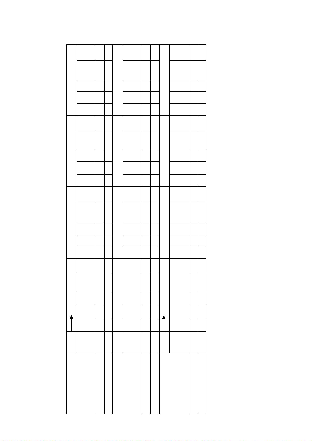
Table 1: Approximate Water Flows & Gas Usage - REU-V1616W/V1620W/V2020W
e
(
)
e
(
)
e
(
)
20
Gas
Cons.
Approx
Pressure
Min Water
L/sec L/min L/hr
Gas
Cons.
Approx
Pressure
Min Water
L/sec L/min L/hr
Gas
Cons.
Approx
(MJ/h)
(kPa)
(MJ/h)
(kPa)
(MJ/h)
Gas
Cons.
Approx
Pressure
Min Water
L/sec L/min L/hr
Gas
Cons.
Approx
Pressure
Min Water
L/sec L/min L/hr
Gas
Cons.
Approx
(MJ/h)
(kPa)
(MJ/h)
(kPa)
(MJ/h)
605045
55
Gas
Cons.
Approx
Pressure
Min Water
L/sec L/min L/hr
Gas
Cons.
Approx
Pressure
Min Water
L/sec L/min L/hr
Gas
Cons.
Approx
(MJ/h)
(kPa)
(MJ/h)
(kPa)
(MJ/h)
(kPa)
Pressure
Min Water
L/sec L/min L/hr
Gas
Cons.
(MJ/h)
Approx
(kPa)
Pressure
Min Water
51015
0.27 16 960 72 25 0.27 16 960 72 50 0.27 16 960 72 75 0.27 16 960 72 100
L/sec L/min L/hr
º C
Input
18-125
Temp
Ris
/ Max Gas
Approx. Min
20-125
(MJ/hour)
Temp
Approx
25 30 35 40
º C
Approx. Min
Ris
Pressure
Min Water
L/sec L/min L/hr
Gas
Pressure
Min Water
L/sec L/min L/hr
/ Max Gas
(kPa)
Cons.
(MJ/h)
(kPa)
Input
(MJ/hour)
0.27 16 960 72 125 0.22 13.2 792 60 125 0.19 11.4 684 44 125 0.17 10.2 612 35 125
18-125
20-125
º C
Temp
Ris
Pressure
Min Water
L/sec L/min L/hr
Gas
Cons.
Approx
Pressure
Min Water
L/sec L/min L/hr
Approx.
Min / Max
Gas Input
(kPa)
(MJ/h)
(kPa)
18-125
(MJ/hour)
0.15 9 540 29 125 0.13 8 480 24 125 0.12 7.2 434 21 125 0.11 6.6 396 20 125
20-125
REU-V1616W
REU-V1616W - Ext.
REU-V2020W 21-160 0.33 20 1200 115 155 0.29 17.4 1044 87 160 0.25 15 900 64 160 0.22 13.2 792 50 160
REU-V2020W - Ext. 21-160 0.33 20 1200 115 31 0.33 20 1200 115 62 0.33 20 1200 115 93 0.33 20 1200 115 124
Models (All Pre-set Temperatures)
Infinity REU-V1616W / REU-V1620W / REU-V2018W / REU-V2020W- 6 - Issue 2 - 21/03/06 ©Rinnai
Models (All Pre-set Temperatures)
Models (All Pre-set Temperatures)
REU-V1616W
REU-V2020W 21-160 0.19 11.4 684 42 160 0.17 10.2 612 35 160 0.16 9.6 576 29 160 0.14 8.4 504 26 160

Water Pressure
As seen in the table below a minimum supply pressure of 80 kPa is required to operate at the rated flow of
16 L/min. In an actual installation, pressure losses in the plumbing system also need to be considered.
Infinity REU-V1616W / REU-V1620W / REU-V2018W / REU-V2020W- 7 - Issue 2 - 21/03/06 ©Rinnai
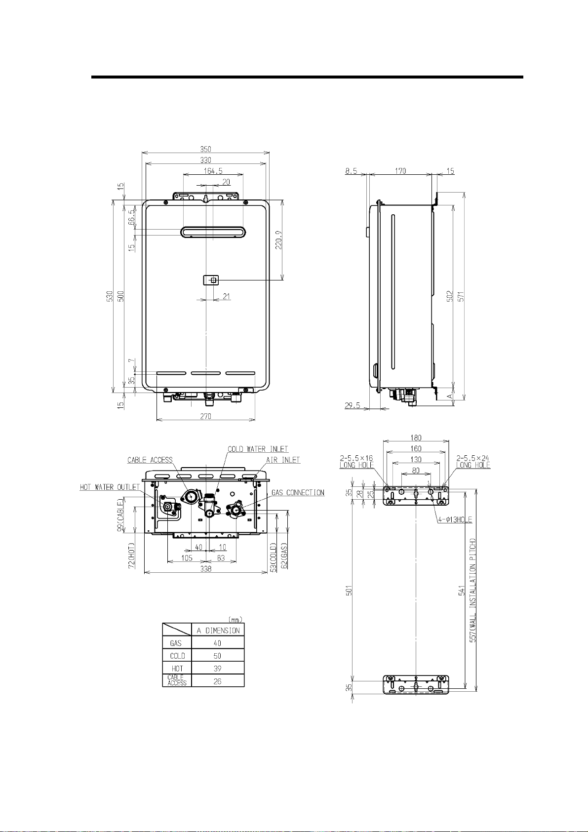
4. Dimensions
REU-V1616W / REU-V1620W
Infinity REU-V1616W / REU-V1620W / REU-V2018W / REU-V2020W- 8 - Issue 2 - 21/03/06 ©Rinnai

REU-V2018W / REU-V20202W
Convector 318H - 9 - ©Rinnai
5. Smartstart
At least one temperature controller model MC-91Q must be used in conjunction with the water heater and
the Smartstart® system. Alternatively, if Temperature Controllers cannot be used a manual activation
switch is available. See separate service manual.
The installation of the water heater and temperature controllers must be performed in accordance with the
installation instructions supplied with the water heater.
The Smartstart® system is designed for domestic installations. However, it may be suitable for certain non
domestic installations. See separate service manual for more information.
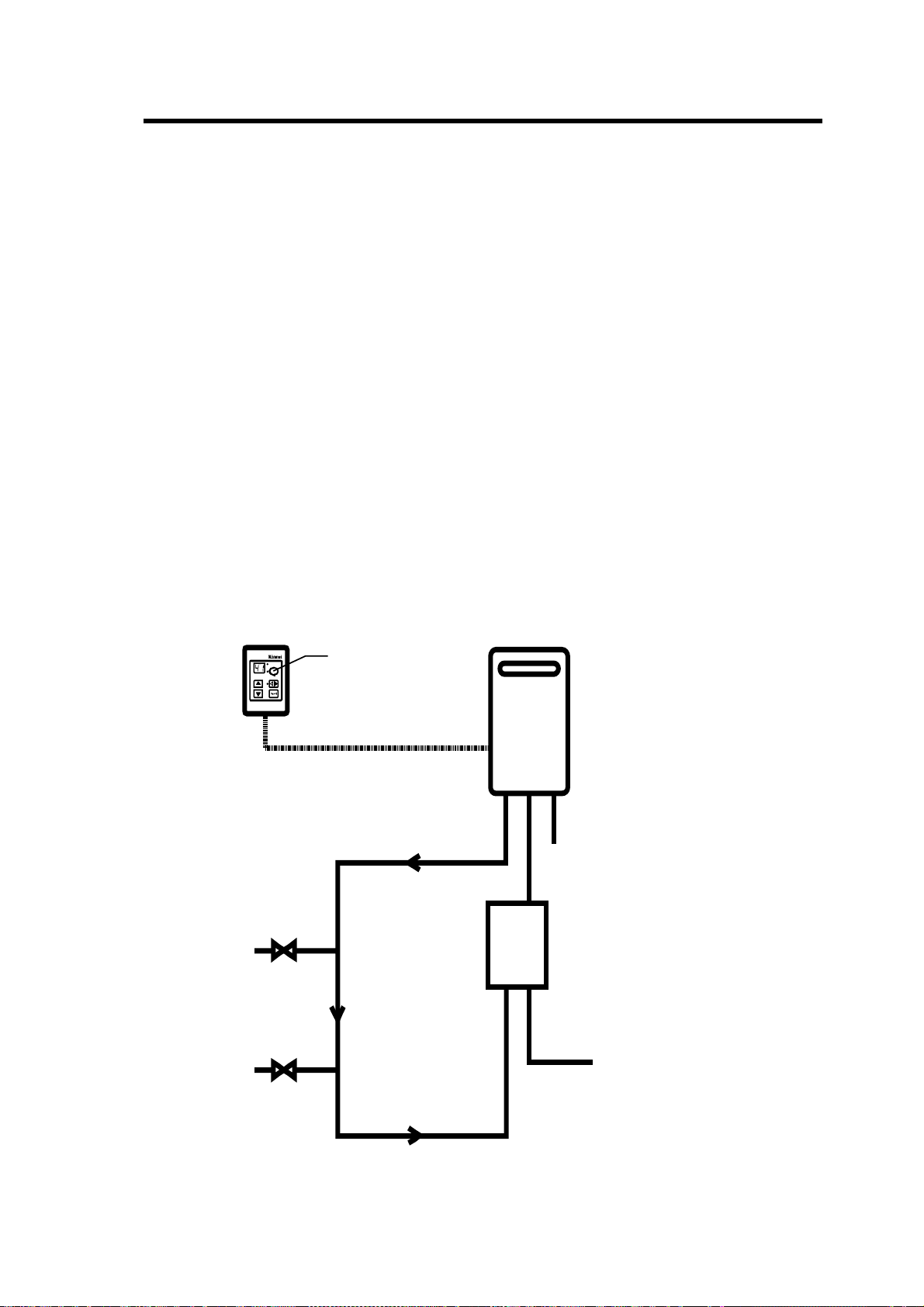
Principle of operation (Fig.2)
The "Smartstart®" system heats the water in the pipework water connected between the water heater and
the hot water outlets before any outlets are opened using the 'flow and return' pipework principle. This
results in water savings and reduced waiting time for heated water delivery from the outlet when opened.
Traditional 'flow and return' systems usually keep the water in the pipework heated continuously. The
Smartstart® system however, only heats the water before the outlet is opened. This results in significant
energy savings because water is not heated unnecessarily whilst retaining the benefits of traditional flow
and return systems.
A schematic of the Smartstart® system installed in conjunction with a Rinnai continuous flow water heater
and temperature controller is shown in Fig.2 below.
One or more
MC-91Q
Controllers
Hot Water
Outlet
Hot Water
Outlet
Preheat Button
Heating Loop Flow
Rinnai Continuous
Flow Water Heater
H
C
O
T
G
O
A
L
S
D
Smartstart®
Module
Cold Inlet Mains
Heating Loop Return
Fig.2
Infinity REU-V1616W / REU-V1620W / REU-V2018W / REU-V2020W- 10 - Issue 2 - 21/03/06 ©Rinnai
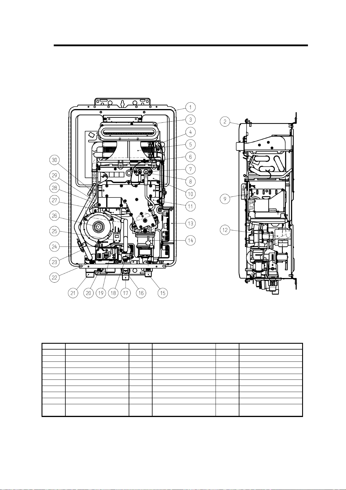
6. Cutaway Diagram
REU-V1616W / REU-V1620W
Part No. Description Part No. Description Part No. Description
1 Casing Assembly 11 Manifold Assembly 21 Hot Water Outlet
2 Front Panel Assembly 12 Transformer 22 Ongoing Water Thermistor
3 Flue Outlet 13 P.C.B. 23 Anti-Frost Heater
4 Overheat Switch 14 Gas Control Assembly 24 Water Flow Control Device
5 Heat Exchanger 15 Gas Connection 25 Frost Sensing Switch
6 Thermal Fuses 16 Water Filter Assembly 26 Combustion Fan
7 Electrode 17 Water Inlet 27 Igniter
8 Flame Rod 18 Water Flow Sensor 28 Water Connecting Pipe
9 Main Burner 19 Surge Protector 29 Hot Water Connecting Pipe
Combustion Chamber Front
10
Plate Assembly
Infinity REU-V1616W / REU-V1620W / REU-V2018W / REU-V2020W- 11 - Issue 2 - 21/03/06 ©Rinnai
20 Pressure Relief Valve
30
By-pass Pipe

REU-V2018W / REU-V2020W
Part No. Description Part No. Description Part No. Description
1 Casing Assembly 11 Manifold Assembly 21 Hot Water Outlet
2 Front Panel Assembly 12 Transformer 22 Ongoing Water Thermistor
3 Flue Outlet 13 P.C.B. 23 Anti-Frost Heater
4 Overheat Switch 14 Gas Control Assembly 24 Water Flow Control Device
5 Heat Exchanger 15 Gas Connection 25 Frost Sensing Switch
6 Thermal Fuses 16 Water Filter Assembly 26 Combustion Fan
7 Electrode 17 Water Inlet 27 Igniter
8 Flame Rod 18 Water Flow Sensor 28 Water Connecting Pipe
9 Main Burner 19 Surge Protector 29 Hot Water Connecting Pipe
Combustion Chamber Front
10
Plate Assembly
20 Pressure Relief Valve
30
By-pass Pipe
Infinity REU-V1616W / REU-V1620W / REU-V2018W / REU-V2020W- 12 - Issue 2 - 21/03/06 ©Rinnai
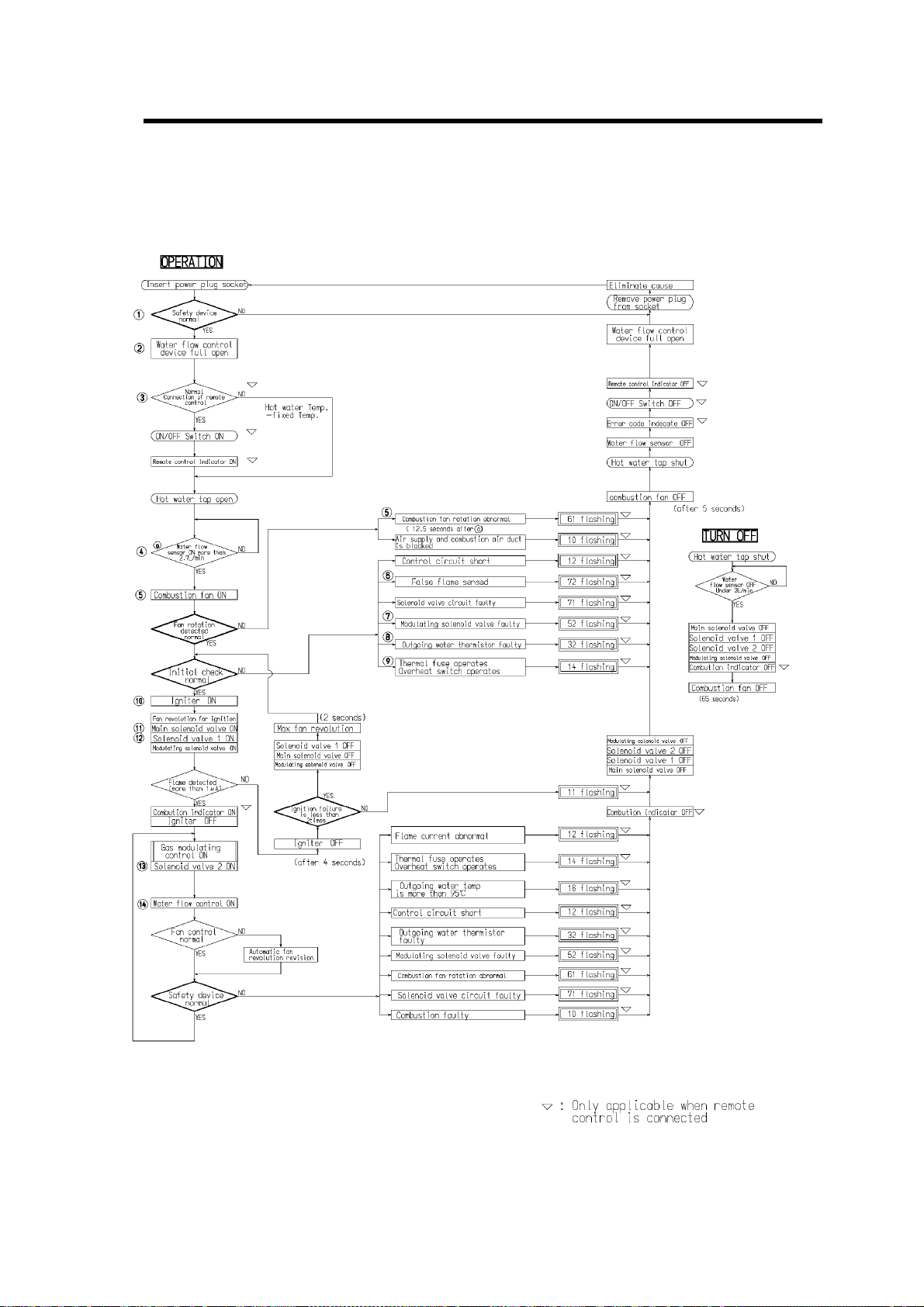
7. Operational Flow Chart
Infinity REU-V1616W / REU-V1620W / REU-V2018W / REU-V2020W- 13 - Issue 2 - 21/03/06 ©Rinnai
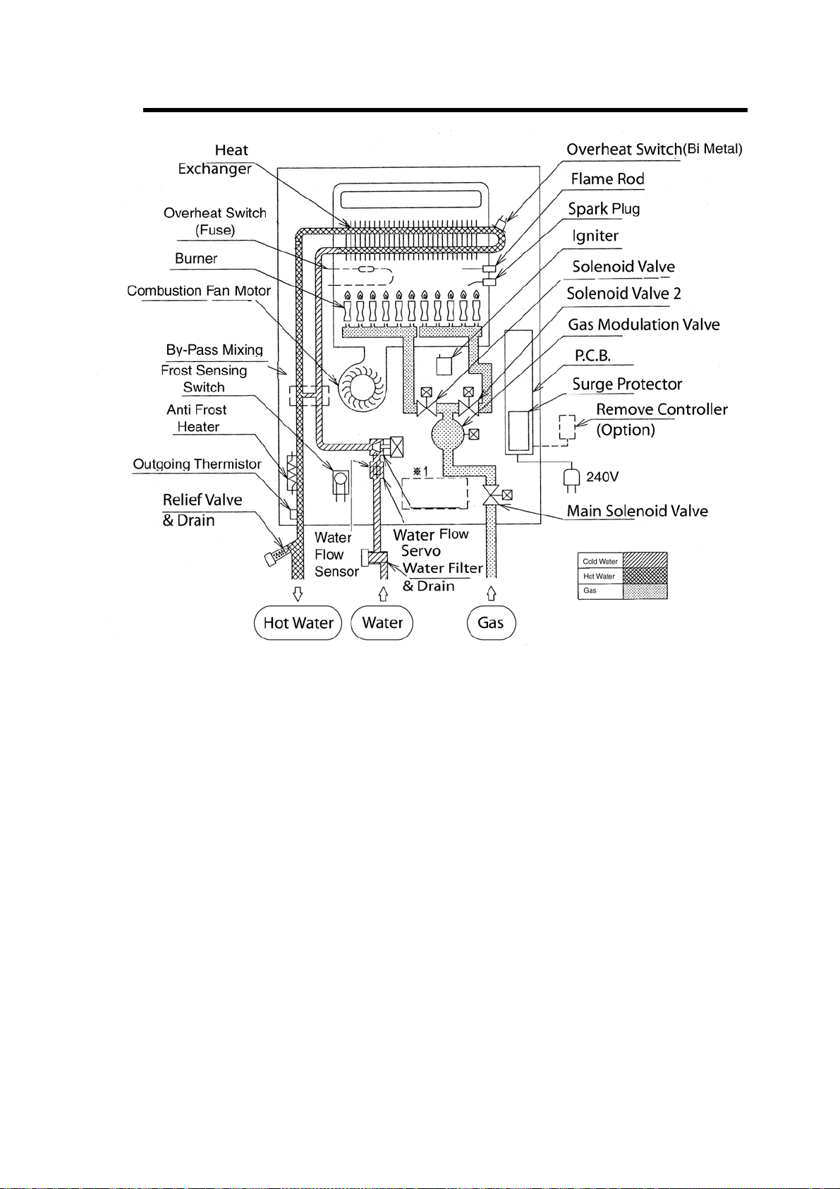
8. Operation Principles
Hot Water Operation
1. Ignition
• Activate controllers (if fitted) an d open the hot water tap (for full details regarding operation of controllers refer
to the ‘How To Use Your Water Heater’ booklet).
• When water flows through the unit, the water flow sensor rotates and sends an electrical ‘pulse’ signal to the
Printed Circuit Board (PCB). This signal is proportional to the water flow rate.
• The PCB sends electrical current to the combustion fan motor causing it to turn. The fan motor sends an electrical
pulse signal to the PCB. If fan rotation is OK, the main solenoid and changeover solenoid valves open as
required, the spark generator activates and the spark electrode ignites the burner.
2. Water Temperature / Flow Control / Volume Control
• The PCB will automatically control operation of the internal components to achieve the programmed
temperature. When a high temperature rise is required, the PCB may cause the Water Flow Servo to close
partially resulting in a lower flow rate to achieve the programmed temperature. This is a necessary operational
feature of the unit.
• When operating in ‘Bath Fill’ mode, t he signal from the water flow sensor is also used by the PCB to com pute
the volume of water that has been passed through the unit at any instant whilst the bath is filling.
3. Shut Down
• When operating in ‘Bath Fill’ mod e, the PCB causes the Water Flow Servo to close when the programmed Bath
Fill volume has passed through the unit. Alternatively, flow is stopped when the user closes the hot water tap.
• When water flow stops, the water flow sensor stops rotating and the pulse signal to the PCB stops. The PCB then
causes the main solenoid and solenoid valves to close and the burner is extinguished. The combustion fan will
continue to operate for some time to purge the combustion chamber.
Infinity REU-V1616W / REU-V1620W / REU-V2018W / REU-V2020W- 14 - Issue 2 - 21/03/06 ©Rinnai

9. Main Components
1) Printed Circuit Board
• The Printed Circuit Board controls all operational functions including Air Supply Control, Gas Control,
Water Flow Measurement, Water Flow Control, Combustion System and all sensors and safety devices.
2) Gas Flow Control
• During normal operation, the PCB keeps the main solenoid valve open whilst there is flow through the
unit and the burner needs to be lit.
• Gas flow rate is controlled by the modulating valve assembly and three changeover solenoid valves to
always ensure constant outlet water temperature, regardless of flow rate or incoming water temperature.
• The modulating valve is electronically controlled by the PCB using signals from the water flow sensor,
water flow control device, water temperature thermistors and combustion fan speed sensor. The
modulating valve directs gas to the three changeover solenoid valves.
• The three changeover solenoid valves direct gas to each of the two burner banks independently. Any one
or two or both of the solenoid valves may be open during operation.
• Gas flow is modulated between 18 and 125 MJ/hr for REU-V1616W/REU-V1620W and between 20
and 160 MJ/hr for REU-V2018W and REU-V2020W by a combination of the modulating valve and
changeover solenoid positions.
• The maximum gas rate is predetermined and the appliance cannot be overloaded when correctly
installed.
3) Water Flow Control
• Water flow is detected by a turbine coupled to a magnetic pulse generating device. The magnetic pulses
are detected and counted by the PCB. The PCB calculates the exact water flow from the frequency of
pulses generated by the turbine. A minimum flow rate of 2.4 L/min. is required for the burner to ignite.
• Water flow control is achieved through the use of servo driven water flow and fixed bypass. Servo
motor is controlled by the PCB. The ‘Water Flow Valve’ restricts the flow of water into the heat
exchanger assembly if the programmed temperature cannot be achieved. During normal operation, c old
water from the inlet valve is mixed with hot water from the heat exchanger outlet.
• The ‘Bypass’ mixes cold and hot water to ensure hot water delivery temperature over the available range
of flow rates.
4) Air Supply Control
• Air for combustion is supplied by a centrifugal fan driven by a variable speed DC motor. The voltage to
the motor is determined by the PCB based on water flow, delivered water temperature and programmed
water temperature. The actual fan speed is monitored by a magnetic pulse counter. This counter emits a
signal to the PCB. From the voltage supplied to the DC motor and the fan speed signal, the PCB
determines whether an error condition exists with the fan.
5) Combustion System
The combustion chamber is housed within the heat exchanger assembly and comprises:
• Aluminium alloy manifold with a total of 28 integral injectors. Gas flow to each chamber is controlled
by an electronic solenoid valve (refer ‘Gas Flow Control’ above).
• A burner assembly comprising fourteen identical modular stainless steel bunsen burners secured by an
aluminised steel framework. The manifold is attached to the front of the burner module. Each bunsen
burner is supplied by two injectors.
• A combustion chamber. Integrated into the combustion chamber front panel are the flame rod and two
ignition electrodes.
Infinity REU-V1616W / REU-V1620W / REU-V2018W / REU-V2020W- 15 - Issue 2 - 21/03/06 ©Rinnai
 Loading...