

Rinnai REU-A2626WG-ZK, REU-A1620WG-ZK, REU-A2024WG-ZK, REU-A2426WG-ZK Installation Manual
Rinnai INFINITY A-Series
continuous ow water heaters
Installation guide
INFINITY A26
INFINITY A24
INFINITY A20
INFINITY A16
REU-A1620WG-ZKREU-A2024WG-ZKREU-A2426WG-ZKREU-A2626WG-ZK
The Rinnai INFINITY A-Series models are not suitable for commercial or solar applications

Important
This appliance must be installed in accordance with:
- Manufacturer’s installation instructions
- Current AS/NZS 3000, AS/NZS 3500, AS/NZS 5601.1 and G12/AS1
For use with Natural Gas or Universal LPG as indicated on the appliance.
Not suitable as a spa or swimming pool heater.
Not suitable for commercial or solar applications.
Appliance must be installed, commissioned and serviced by an authorised
person, being in New Zealand a licensed gasfitter, in accordance with these
instructions and all applicable local rules and regulations.
Warning
Improper installation, adjustment, alteration, service and maintenance can
cause property damage, personal injury or loss of life.
For more information about buying, using, and servicing of Rinnai
appliances call: 0800 RINNAI (0800 746 624).
Rinnai New Zealand Limited
105 Pavilion Drive, Mangere, Auckland
PO Box 53177, Auckland Airport, Auckland 2150
Phone: (09) 25 7-3800
Fax: (09) 257-3899
Email: info@rinnai.co.nz
Web: rinnai.co.nz
youtube.com/rinnainz
facebook.com/rinnainz

cnt:
Before installation .......................................4
Appliance location ......................................4
General installation information
..................
5
Water delivery temperature ........................6
Connections and fittings ............................. 7
Dimensions (mm) ........................................ 8
Commissioning ...........................................10
PCB interface and dip switch settings ..........12
Flue diverter dip switch changes ................. 14
Appendix 1
Water controller communication cables ..... 15
4 | A-Series CFWH installation guide 01-18
Before installation
• Check for damage: Unpack the appliance and check for damage. DO NOT install any
damaged items.
• Check components and gas type: Check all components have been supplied and that you
have the correct gas type.
• Read these instructions: Get an overview of the steps required before starting the
installation. Failure to follow these instructions could cause a malfunction of the appliance.
This could result in serious injury and property damage.
• Applicable models: These instructions apply only to the Rinnai A-Series continuous flow
water heater models listed on the cover page of this guide.
Appliance location
This appliance is designed for outdoor
installations only. It MUST BE located above
ground in open air with natural ventilation,
without stagnant areas, where gas leakage
and products of combustion can be rapidly
dispersed by wind and natural convection.
The appliance MUST BE mounted on a vertical
structure with the water and gas connections
on the underside pointing downwards.
Location of the flue terminal MUST BE in
accordance with Section 6 and Figure 6.2 of
the AS/NZS 5601.
The appliance MUST BE placed as close
as practicable to the most frequently
used hot water outlet or outlets to reduce
the delay time for hot water delivery1. For
installations where the distance between the
water heater and the outlets is considerable,
a flow and return system can be used to
minimise the waiting time for hot water
delivery. Alternatively multiple appliances can
be strategically placed to serve outlets with
minimal delay time.
An AC 230 V, 10 A earthed power point must
be provided adjacent2 to the appliance. This
power point must be weatherproof. It must be
clear of the gas and water connections to the
appliance and also the flue exhaust and water
pressure relief valve. The power cord of the
appliance is 1.5 m long.
All appliances MUST BE installed to ensure
access can be gained without hazard or undue
difficulty for maintenance and servicing.
Sufficient clearances shall allow access and
removal of all serviceable components.
Appliances should not be mounted more than
2.5 m above the ground or floor level unless
the customer can arrange permanent and safe
access, or can provide another means of safe
access.
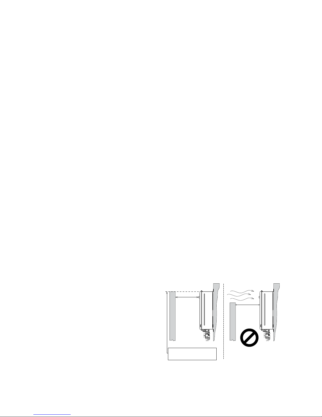
Horizontal obstructions
AS/NZS 5601 states a minimum horizontal
clearance of 500 mm between a building
structure and obstruction facing the terminal.
At 500 mm the obstruction needs to be the
full height of the unit (as shown), and not a
partial obstruction. A partial obstruction of
less than 1 m could result in wind pushing the
flue gases back into the flue terminal.
500 mm
At 500 mm the obstruction
needs to be the full height of
the unit.
500 mm
DO NOT
1
Rinnai recommend a maximum pipe run of 10 m.
2
Power point can be within the pipe cover if a pipe cover is installed—must comply with AS/NZS Wiring rules
A-Series CFWH installation guide 01-18 | 5
General installation information
Securing the Rinnai INFINITY
The wall or structure on which the units are
mounted MUST BE capable of supporting the
weight of the appliance and associated pipe
work. Refer p. 7 for the specific model weight.
Ensure that suitable fixing screws or bolts
are used to secure the unit to the wall, in
accordance with AS/NZS 5601 section 6.
Wooden plugs shall not be used.
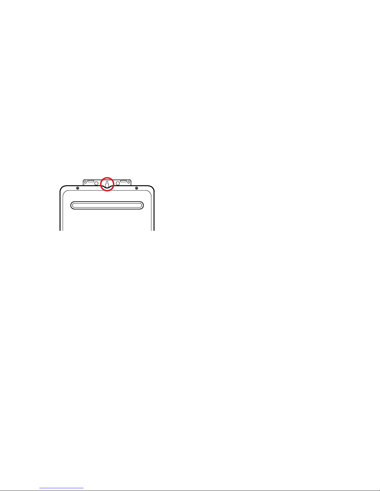
The top bracket has a keyhole slot so that the
appliance can be positioned by hanging it on
one screw, once in position the appliance can
then be secured with appropriate fittings.
The appliance can be mounted directly
against the wall or structure. There is no need
to use non-combustible sheeting between the
appliance back panel and the wall or structure
for the purposes of meeting the temperature
hazard requirements of AS/NZS 5601.
Pipe sizing
If the gas pipe sizing is insufficient the
appliance won’t perform properly. Gas pipe
sizing must consider the gas input into this
appliance as well as other gas appliances in the
premises. The gas meter and regulator must
be specified for this gas rate.
An approved sizing chart such as the one in
AS/NZS 5601 should be used. Refer p. 7 for
model specific gas consumption details.
Water pipe sizing and layout should be
performed in accordance with AS/NZS 3500.
All hot water pipe work should be insulated to
optimise performance and energy efficiency.
Water supply
The appliance is intended to be permanently
connected to the water mains.
Refer p. 7 for model specific operational
water pressure limitations. Approved
pressure limiting valves may be required if
the maximum rated water supply pressures
are exceeded. To achieve the rated flow, the
minimum water supply pressures must be
met.
The A-Series water heaters will operate at
lower pressures than the specifications, but
will not achieve the rated flow. Contact Rinnai
for gravity fed or low pressure installations.
Water chemistry and impurity limits are
detailed in the operation guide within the
warranty section. Most metropolitan water
supplies fall within the requirements.
If you are unsure about your local water
quality, contact your water authority. If sludge
or foreign matter is present in the water
supply, a suitable filter or strainer should be
incorporated in the water supply to the Rinnai
INFINITY.
 Loading...