

Rinnai REU-2018W, REU-2020W, REU-2422W, REU-2425W Service Manual
INFINITY
REU-2018W
REU-2020W
REU-2422W
REU-2425W
SERVICE MANUAL
Infinity Compact Continuous Flow Gas Hot Water System
All Rinnai products are certified by the
Australian Gas Association as compliant
to relevant Australian Standards.
Rinnai Australia Head Office is certified
as complying with ISO 9001 by SAI
Global.
SAI Global
Rinnai New Zealand has been certified to
ISO 9001 Quality Assurance by Telarc.
All Rinnai products are Certified to
WaterMark by SAI Global. WaterMark
certification is awarded to products and
fittings complying with safety and water
contamination standards.
© Copyright Rinnai Australia Pty Ltd
A.C.N. 005 138 769 A.B.N. 74 005 138 769
All rights reserved
Produced by Technical Services Department
2004 - Issue 2
No portion or part of this manual may be copied without prior permission from Rinnai Australia.
Rinnai Australia takes no responsibility for the accuracy or otherwise of information contained in
this manual, and reserves the right to make modifications and change specifications without notice.
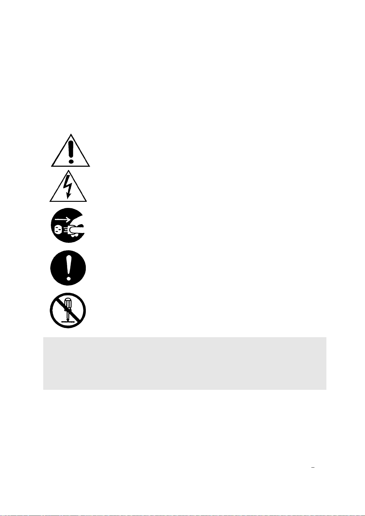
Key to Warning Symbols
Failure to comply with the following instructions may result in serious
personal injuiry or damage to the appliance.
Be careful of possible electric shock. Wiring inside this appliance may
potentially be at 240 Volts.
Remove the plug from the source when carrying out any of the following
activities.
Read Fault Diagnosis and Wiring Diagram carefully to avoid incorrect wiring
Do not disassemble. Parts within cannot be exchanged or diagnosed faulty.
Please follow instructions carefully to ensure safe and appropriate service.
After completing the service and confirming that there no gas leaks or incorrect wiring,
test operation of unit according to the Customer Operating Instructions. After confirming
normal operation, explain what was serviced to the customer and operation principles if
necessary.
This manual has been compiled by Rinnai Australia Technical Services Department. While many
individuals have contributed to this publication, it will be successful only if you - the reader and
customer - find it useful. We would like to extend an invitation to users of this manual to make
contact with us, as your feedback and suggestions are valuable resources for us to include as
improvements. Rinnai are constantly working toward supplying improved appliances as well as
information, and specifications may be subject to alteration at any time.
SM Infinity REU-2425W
Issue N
o
2

Table of Contents
1. Introduction ................................................................................................... 3
2. Features ....................................................................................................... 4
3. Dimensions ................................................................................................... 5
4. Remote Controls .......................................................................................... 6
5. Safety Devices ............................................................................................. 9
6. Specification ............................................................................................... 10
7. Cut-away Diagram ...................................................................................... 11
8. Schematic Diagram .................................................................................... 12
9. Combustion Specification ........................................................................... 13
10. Dip Switch Positions ................................................................................. 14
11. Water Flows ............................................................................................. 16
12. Main Components .................................................................................... 18
13. Time Charts .............................................................................................. 20
14. Operation Flow Principle .......................................................................... 21
15. Operation Principles ................................................................................. 23
16. Fault Finding ............................................................................................. 25
17. Fault Finding Table ................................................................................... 26
18. Maintenance Monitor / Error History ......................................................... 27
19. Component Circuit Value Table ............................................................... 29
20. Wiring Diagram ......................................................................................... 30
21. Fault Diagnosis ......................................................................................... 31
22. Electrical Component Analysis ................................................................. 40
23. Gas Conversion ........................................................................................ 43
24. Gas Pressure Setting Procedure .............................................................. 44
25. Dismantling for service ............................................................................. 45
26. Exploded Diagram .................................................................................... 51
27. Parts list .................................................................................................... 55
Infinity REU-2425W - 1 - Issue 2 - 5/07/04 ©Rinnai

Glossary of Terms and Symbols
This glossary of terms and symbols is provided to assist you in understanding some of the
language used throughout this manual.
dB(A) - sound pressure level in decibels, “A” range
DC - direct current
AC - alternating current
WFCD - water flow control device
FB - feedback information
Hz - Hertz
IC - integrated circuit
kcal/h - kilocalorie per hour
kPa - kilopascals
LED - light emitting diode
L/min - Litres per minute
mA - milliamps
MJ/h - megajoule per hour
mm - millimetres
mmH2O - millimetres of water (guage pressure)
NO
X
- oxides of nitrogen (NO & NO2)
OHS - overheat switch
PCB - printed circuit board
CPU - central processing unit
POT - potentiometer
rpm - revolutions per minute
SV - solenoid valve
ø - diameter
o
C - temperature rise above ambient
∆
POV - modulating valve
TE - thermal efficiency
TH - thermistor
T
IN
T
OUT
Infinity REU-2425W - 2 - Issue 2 - 5/07/04 ©Rinnai
- temperature of incoming water
- temperature of outgoing water

1. Introduction
The brand name Infinity refers to “Endless Hot Water”. The Infinity 24 has been developed in
response to the growing changes in the lifestyle of consumers, and the increasing diversification
and sophistication of demand in the marketplace.
The Infinity series offers reduced cost, advanced safety features, and an option to connect one,
two, or three remote control pads.
The Infinity 24 is delivered with the maximum hot water temperature of 50oC, with or without
remote controls connected.
About the Infinity
The front cover of each appliance in this series is formed from 0.6 mm coated steel, secured to
the main box assembly by 4 screws. Seals around the front cover and flue outlet prevent water
from entering the appliance.
Air inlets are situated in the front panel. The general layout of components is shown on the
cutaway diagram on
coated steel.
page 11. All components are supported within a box formed from 0.8 mm
The heat exchanger occupies the top section of the box, and the burner is situated in a chamber
formed from 0.8 mm aluminised steel attached to the bottom of the heat exchanger.
The air for combustion is supplied by a fan which is connected to the burner box by a duct at the
left hand side of the appliance.
Gas and water controls are situated at the bottom right of the appliance, directly under the
manifold. The products of combustion are expelled from the appliance through a flue outlet
situated on the front of the appliance, at the top.
The burner assembly is made up of 18 identical stainless steel bunsen burners, secured by an
aluminised steel framework. An aluminium manifold with 18 integrally moulded injectors supplies
gas to the burners, and is attached to the lower front cover of the burner box.
There is one thermistor, it is located on the outgoing hot water supply tube, near the outlet of the
heater.
Infinity REU-2425W - 3 - Issue 2 - 5/07/04 ©Rinnai

2. Features
Installation
The light-weight, slim, and compact form enable easier, improved appearance installations. The
remote controls (where fitted) are connected to the appliance by 2-core non-polar cable, ensuring
easy wiring and eliminating misconnection problems.
Low Noise Level
Low noise level design enables these appliances to be installed in units, flats, townhouses, and
other high density residential areas with little concern about noise disturbances.
Safety
Various safety devices controlled by a micro-computer ensure complete safety. Also, the antifrost device (where fitted), automatically prevents the water inside the appliance from freezing by
using small electrical ceramic heaters connected to the pipework at strategic locations.
Economy
Direct electronic ignition to the main burner eliminates wasteful pilot gas consumption. The
combustion fan rpm is proportionally controlled with gas consumption. This maintains high energy
efficiency as the gas consumption changes.
Water Supply Control
The water supply capacity varies proportionally from 2.7 L/min to 24 L/min. A suitable volume of
hot water can be supplied throughout all seasons by the water flow control device and water flow
servo mechanism. REU 2425W model will supply up to 24L/min, (maximum unmixed), controlled
by an automatic electro-mechanical water flow device. See
details on water flow.
“Water Flows” on page 16 for precise
Water Temperature Control
With a remote control connected, the hot water control range is between 37°C and 50°C (in 12
steps). With or without a remote control connected the outgoing hot water temperature is fixed to
50°C maximum with no remote. This means that the Infinity Series can be set to comply with
various State laws on temperature control in homes, child care centres, and elderly care centres.
The maximum temperature selectable on the bath remote control is 50°C (this is a safety feature).
Over Temperature Protection
All Infinity models incorporate a device to prevent the hot water temperature exceeding the preset temperature by more than 3°C.
Temperature Locks
With the remote control(s) connected, the pre-set water temperature can only be altered between
37°C and 43°C while the hot water is flowing. This helps to avoid inadvertently increasing the
temperature to a hazardous level whilst someone is in the shower. While the water is flowing, the
remote control(s) can be turned off, but not on again.
Infinity REU-2425W - 4 - Issue 2 - 5/07/04 ©Rinnai
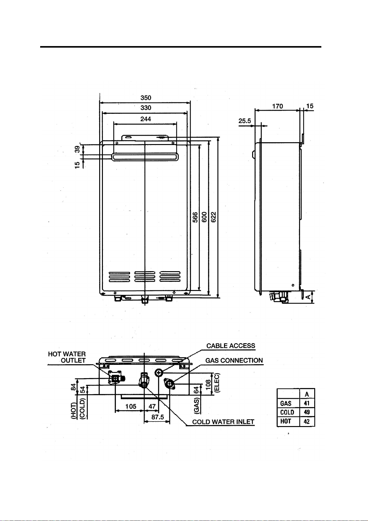
3. Dimensions
Note: All dimensions are in mm.
Infinity REU-2425W - 5 - Issue 2 - 5/07/04 ©Rinnai
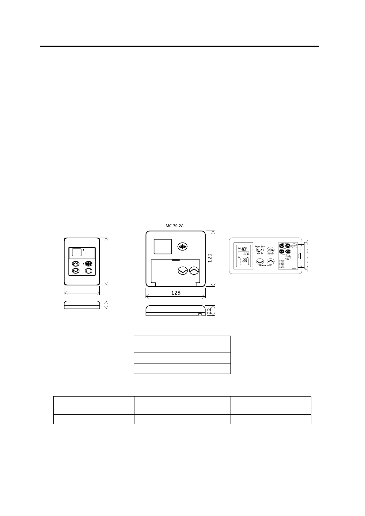
4. Remote Controls
BC-70-2A
Remote Controls
Remote Controllers are an optional extra. 'Universal' and 'Deluxe' Controllers can be fitted.
Universal controllers allow temperature selection only. Deluxe controllers have temperature
selection, bath-fill and voice prompting functions. For detailed information regarding controller
operation refer to the 'How to use your water heater' booklet supplied with the appliance. Other
manufacturers' controllers are NOT compatible with this appliance.
Universal Controller (Model: MC-91-1A)
Up to 3 Universal Controllers can be fitted to the appliance. They are normally installed in the
areas where the majority of hot water is used, for example, the Kitchen, Bathroom, Ensuite and
Laundry.
Deluxe Controllers (Models: MC-70-2A) and (BC-70-2A)
Deluxe Controllers have 'Kitchen' (MC-70-2A) and 'Bathroom' (BC-70-2A) versions. 'Kitchen'
Controls are intended for the Kitchen or other convenient area where the majority of hot water is
used. 'Bathroom' Controllers are intended to be fitted in the Bathroom or ensuite and allow the
user to have a bath filled to the required level and temperature automatically.
MC-91-1A
120
90
20
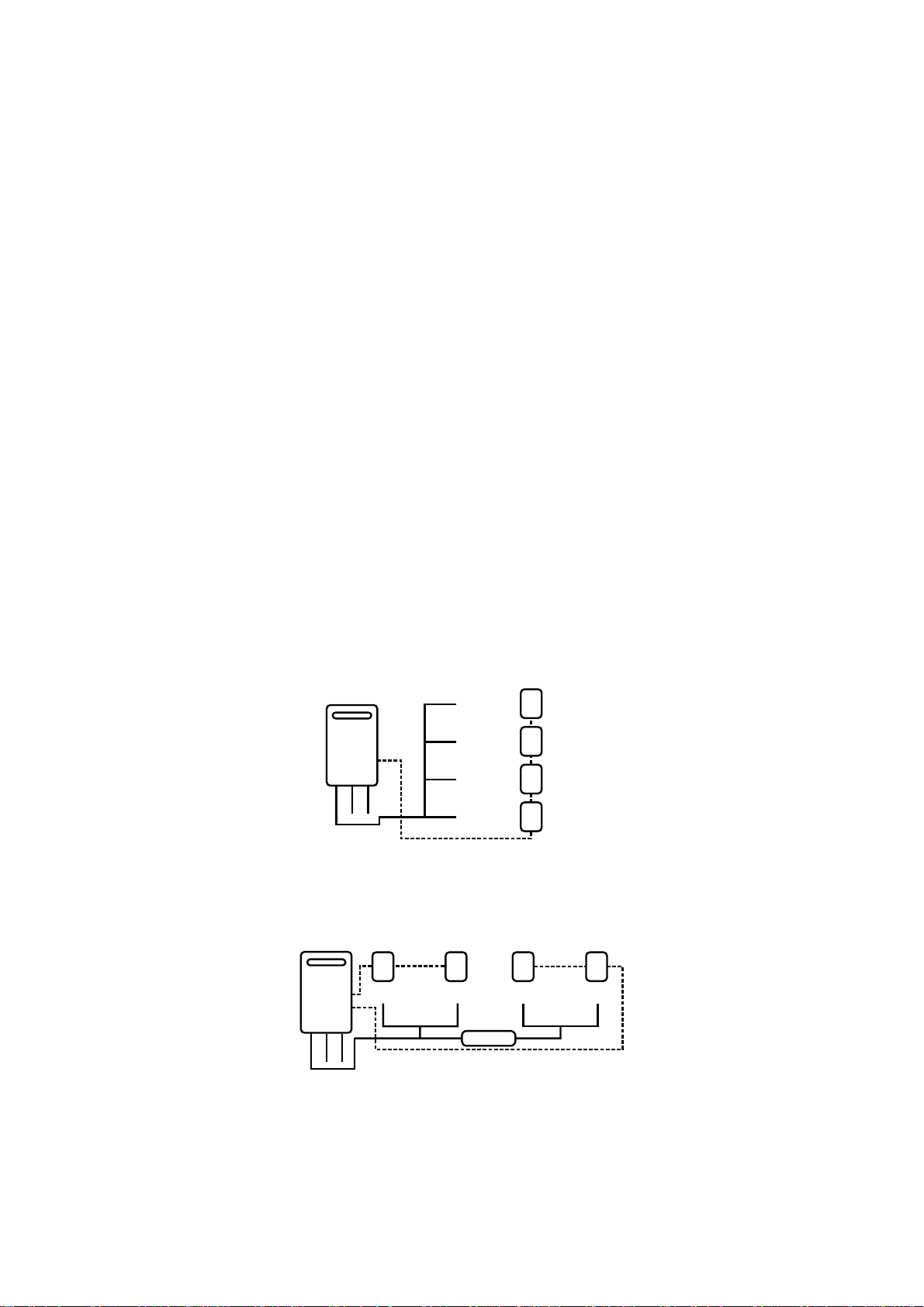
Up to two ‘Deluxe” controllers can be connected as follows:
Kitchen Bathroom
MC-70-2A
MC-70-2A BC-70-2A
If a Third controller is required, a ‘Unviersal’ controller can be included as follows:
Kitchen Bathroom Laundry
MC-70-2A BC-70-2A MC-91-1A
Positioning of Controllers
Controllers must be installed in shaded and clean locations. They should be fitted out of reach of
children (suggested height from floor at least 1500mm). Controllers are water resistant, however,
durability is improved when positioned outside the shower recess or at leat 400mm above the
highest part of a sink, basin or bath.
Infinity REU-2425W - 6 - Issue 2 - 5/07/04 ©Rinnai
DO NOT INSTALL THE CONTROLLERS
• NEAR A HEAT SOURCE, SUCH AS A COOK TOP, STOVE OR OVEN. HEAT, STEAM,
SMOKE AND HOT OIL MAY CAUSE DAMAGE.
• IN DIRECT SUNLIGHT.
• OUTDOORS UNLESS AN ENCLOSURE IS PROVIDED WHICH PROTECTS THE
CONTROLLER AGAINST SUNLIGHT AND DUST INGRESS.
• AGAINST A METAL WALL UNLESS THE WALL IS EARTHED IN ACCORDANCE WITH AS/
NZ3000.
Remote Controller Connection
Remote controls operate at extra low voltage (12 Volts DC) which is supplied from the appliance.
Controllers are supplied with 15 m of electrical cable. The cable wires for connection to the
appliance are fitted with spade terminals.
Extension cables are available from Rinnai. Alternatively, a two core sheathed (double insulated)
flex with minimum cross-sectional area of 0.5 mm² can be used. Maximum cable length is 50 m.
For connection refer to the “CONNECTING REMOTE CONTROL CABLES” section.
Water Heater and Controller installation configurations
If there is a label on the appliance casing that contains the text ”This appliance delivers water
not exceeding 50°C”, local regulations may permit it’s installation without a Temperature
Limiting Device. Installations without a Temperature Limiting Device are shown in Diagram 1.
If you are unsure about your local regulations contact your regulating authority or Rinnai.
If the appliance does not have this label, or your local regulations require installation with a
Temperature Limiting Device then install the appliance in accordance with Diagram 2.
Temperature
controller
(optional)
Temperature
controller
(optional)
Temperature
controller
(optional)
Temperature
controller
(optional)
H
O
T
50º C
C
O
L
D
G
A
S
Diagram 1. 50º C Appliance
KITCHEN
LAUNDRY
BATHROOM
ENSUITE
Temperature
controller
(optional)
KITCHEN
H
C
G
O
O
A
T
L
S
D
Diagram 2. Not a 50º C Appliance
Note: TLD = Temperature Limiting Device.
Temperature
controller
(optional)
LAUNDRY BATHROOM
TLD
Temperature
controller
(optional)
Temperature
controller
(optional)
ENSUITE
IMPORTANT: If the appliance is to deliver water primarily for the purposes of personal hygiene
in an early childhood centre, primary or secondary school, nursing home or similar facility for
young, aged, sick or disabled persons as defined in AS/NZ3500.4 a Temperature Limiting Device
(TLD), such as a Tempering Valve, may be required even if the appliance is set to 50º C or less.
For these types of applications contact Rinnai.
Infinity REU-2425W - 7 - Issue 2 - 5/07/04 ©Rinnai
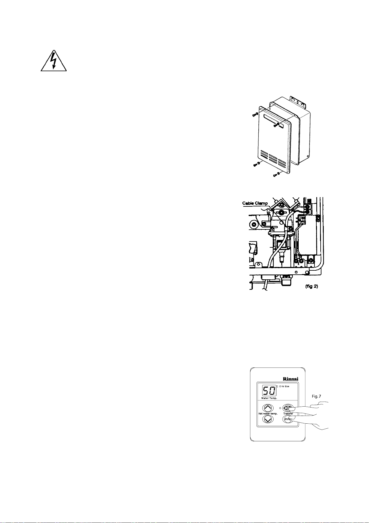
Connecting remote control cables
Do not attempt to connect the remote control cable terminals to the appliance with the
power on.
RISK OF ELECTRICAL SHOCK
Connecting One or Two Controllers
1. Isolate the power supply.
2. Remove the front cover from the Appliance (4 screws) fig. 1.
3. Thread the cable(s) through the cable access hole at the base of the appliance.
4. Locate the terminals for controls, the position of which is marked on
the Printed Circuit Board casing. Connect the space connectors to
the terminals on the P.C.B. (Fig. 2). Polarity is not important. Either
wire colour can be connected to either terminal.
5. Replace cover of the Appliance. Ensure that the special screw is placed at the bottom right hand corner for earthing purposes.
Connecting Three Controllers
1. Isolate the power supply.
2. Remove the front cover from the Appliance (4 screws) fig.1.
3. Cut the spade connectors from 2 of the controller cables to be
connected to the appliance (4 spade connectors should be cut off)
and discard. Connect the wires from these two cables and
terminate into two new spade connectors as shown in fig.3. Spade
connectors are available from your local electrical component
retailer.
4. Located the terminals for controls, the position of which is marked
on the Printed Circuit Board casing. Connect the 4 spade
connectors to the terminals on the P.C.B. (Fig. 2). Polarity is not
important. Either wire colour can be connected to either terminal.
5. Replace cover of the Appliance. Ensure that the special screw is placed at the bottom right hand corner for earthing purposes.
fig.1.
MC-91A Controller Programming
Is there a label on the appliance casing that contains the text.
“THIS APPLIANCE DELIVERS WATER NOT EXCEEDING 50° C
IF YES:No further action required.
IF NO: You will need to program Kitchen controller to enable selection of
temperatures higher than 50º C.
STEP 1:
For the controller in the KITCHEN only, press and hold the 'Transfer'
and 'On/Off' buttons simultaneously (see Fig 7.) until a 'beep' is heard
(approximately 5 seconds).
STEP 2:
When the controller fitted in the KITCHEN is switched on, it should be
possible to select temperatures higher than 50º C. If not, repeat Step 1.
Note:
• If the kitchen controller is replaced, repeat STEP 1 above for the replacement controller.
• If the kitchen controller is swapped with another controller (for example, the controller fitted in a
bathroom), repeat STEP 1 for the controller moved from the kitchen to the bathroom. Then perform
STEP 1 for the controller moved from the bathroom to the kitchen.
Infinity REU-2425W - 8 - Issue 2 - 5/07/04 ©Rinnai

5. Safety Devices
Flame Failure
Situated to the right of the burner at the front, the flame rod monitors combustion, preventing any
discharge of gas to the burner if there is no flame, by sending a signal to the PCB which in turn
isolates the gas.
Over Heat Protection Device
Also referred to as an Over Heat Switch. This device is fitted to a bend section at the inlet to the
heat exchanger. If the flame remains on the burner after the tap is closed, and the water
temperature inside the heat exchanger reaches 97°C, a DC 12 volt bi-metal cut-off switch isolates
the gas to the solenoids.
No Water
Should the incoming water flow become restricted or stop, then the water flow sensor will cease
to send a magnetic pulse signal to the PCB, in turn isolating the flow of gas to the burner.
Thermal Fuse
Wrapped around the entire surface of the heat exchanger, if the heat exchanger burns out, or the
temperature outside it reaches 129°C, the thermal fuse melts, breaking the electronic circuit.
Current to the gas solenoid valve circuit is cut, and combustion stops, shutting down the unit.
Pressure Relief Valve
This spring and seat type valve located on the hot water outlet will release the built up pressure
if the pressure inside the heat exchanger reaches 2100 kPa until 1500 kPa is maintained.
Combustion Fan Revolution Check
The combustion fan rpm is continually monitored by a magnetic pulse counter connected to the
PCB. If the fan revolutions deviate from the speed required for complete combustion, a signal is
sent to the PCB and the revolutions adjusted accordingly. (If not the unit shuts down)
Automatic Frost Protection
When the outdoor temperature drops and the temperature inside the appliance goes below 3.5°C,
the frost sensing device is activated, and the anti-frost heaters prevent the water in the appliance
from freezing. These anti-frost heaters remain ON until the temperature inside the appliance rises
to 11.5°C. There are 5 x 16 Watt anti-frost heaters located at various points in the main water flow
area of the appliance. The anti-frost protection device will prevent freezing down to -20°C in a no
wind situation, and -15°C in a windy situation.
3°C Over Temperature Cut-Off
The temperature of the outgoing hot water is constantly monitored by the water temperature
thermistor located near the outlet of the appliance. If the outgoing water temperature reaches 3°C
above the preset temperature, the burner will automatically go out. The burner will only ignite
again once the outgoing hot water temperature falls below the preset temperature.
Infinity REU-2425W - 9 - Issue 2 - 5/07/04 ©Rinnai

6. Specification
Rinnai Model No. REU-2425W
Type of appliance Temperature controlled continuous flow gas hot water
system.
Operation With or without remote controls, mounted in kitchen,
bathroom, or ensuite.
Exhaust system Forced combustion
Installation Externally mounted
Maximum gas rate 188 MJ/h
Minimum gas rate 21 MJ/h
Output (Kw) 41.7
Efficiency rating 80%
Hot water capacity, unmixed 2.7 to 24 L/min
Hot water capacity, mixed (25°C rise) 2.7 to 24 L/min
Default temperature (without remote)
(Set using switches on PCB)
Maximum temperature ceilings
(remote connected)
Temperature range (with remote) 37 to 50°C in 13 steps
Approved gas types Natural; Propane
Dimensions Width - 350 mm
Weight 18 kilograms.
Noise level 49 dB(A)
Connections Gas supply- R: / 20mm
Ignition system Direct electronic ignition
Electrical consumption (Watts) Normal -
Water temperature control Simulation feedforward and feedback
Water flow control Water flow sensor & automatic electro-mechanical water
Minimum operating pressure 200 kPa
Nominal operating pressure 200 ~ 1200 kPa
Power supply Appliance- AC240 Volts 50 Hz.
Safety devices Flame failure- Flame rod.
Remote control MC-91-1A- Universal control
Remote control cable Non polarised two-core cable
50°C
(40,43,50,55,60,65,75°C)
50°C (set by combination of switches on PCB)
Other temp.settings than 50°C avail. from alternative PCB
Height - 600 mm
Depth- 170 mm
Cold water inlet- R: / 20mm
Hot water outlet- R: / 20mm
55
Standby Anti frost protection -
flow control device
Remote control- DC12 Volts (Digital)
Boiling protection- 105°C lockout thermistor (25 seconds)
Remaining flame [OHS]- 97°C bi-metal switch
Thermal fuse- 129°C
Pressure relief valve- Opens-2100kPa, closes-1500 kPa
Automatic frost protection- Bi-metal sensor & anti-frost
heaters
Combustion fan rpm check- Integrated circuit system
Over current- Glass fuse (5 Amp).
MC-70-2A- Kitchen control
BC-70-2A- Bathroom control
8
80
Infinity REU-2425W - 10 - Issue 2 - 5/07/04 ©Rinnai
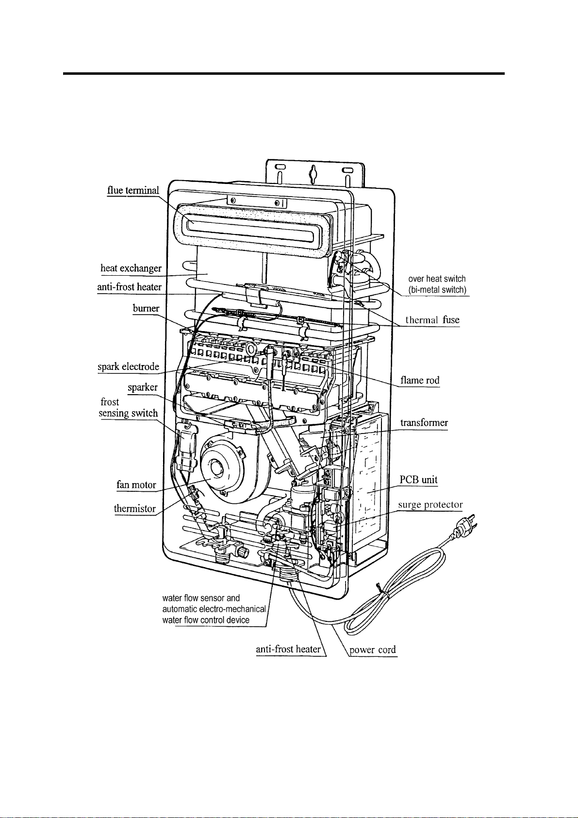
7. Cut-away Diagram
Infinity REU-2425W - 11 - Issue 2 - 5/07/04 ©Rinnai

8. Schematic Diagram
Infinity REU-2425W - 12 - Issue 2 - 5/07/04 ©Rinnai

9. Combustion Specification
REU-2425W
Input NG/Propane
LPG #
Gas Consumption NG/Propane
LPG #
Integral Injector size (18) NG mm ø 1.7
Propane/LPG # ø 1.0
Damper (1 piece) NG NIL
Propane/LPG # A
Pressure NG HI kPa 0.90
Propane/LPG # HI kPA 2.26 (1.90)
Burner type NG/
Dip Switch positions Refer to page 14
HI MJ/h 188
LO 21
HI kW 52.3 (50)
LO 5.93
LO 0.08
LO 0.17 (0.15)
Propane Common
Note: LPG values specified in brackets are for New Zealand.
Infinity REU-2425W - 13 - Issue 2 - 5/07/04 ©Rinnai
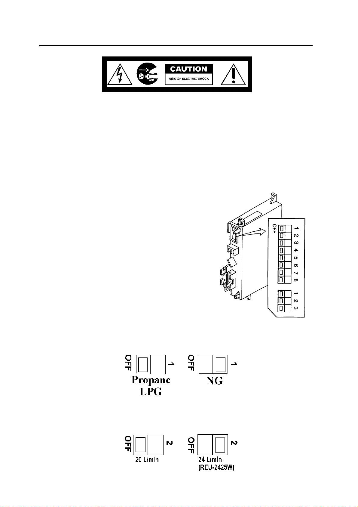
10. Dip Switch Positions
Please do not adjust the DIP Switch Positions before reading this information.
The dip switches are provided so that the water heater can be set to different operating
configurations. In some instances such as nursing homes or even domestic situations, it may be
necessary to limit the temperature of the hot water coming from the units.
The set-up configuration for the water heater differs depending on:
• Gas type
• Maximum water flow select
• Temperature limiting requirements
• Alternate type
DIP Switches explained
Top switch settings 1 ~ 8
1: Gas type (used only during conversion)
2: To select maximum water flow volume
4 to 8: To select the temperature with or without remote
connected.
Bottom switch settings 1 ~ 3
1: Factory use (To select the capacity of appliance)
2 & 3: Combustion control
The Infinity REU-2425W model delivers maximum hot
C, however alternative
water temperature limited to 50
PCB for the other maximum temperature of hot 40°C,
43°C, 50°C, 55°C, 60°C, 65°C, or 75°C available.
°
1. Gas Type
Only alter gas type positions when converting. For conversion instructions refer to page 43.
2. Maximum Water Flow Select
Infinity REU-2425W - 14 - Issue 2 - 5/07/04 ©Rinnai
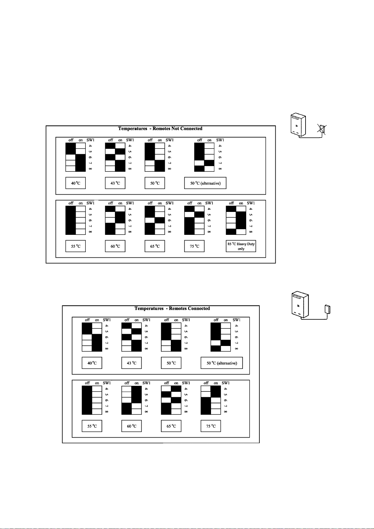
3. Temperature Limiting
There are different positions, depending on the temperature limit required and whether the
remote controls are connected or not.
Dip Switch Settings for Alternative PCB
a. Fixed hot water temperature ‘‘without’’ remote connected
Upper limit hot water temperature ‘‘with’’ remote connected
Note:
a) The black squares indicate the position of switches.
b) It will be noted that some dip switch configurations are the same for a given temperature
whether controllers are connected or not. These similarities are not mistakes.
Infinity REU-2425W - 15 - Issue 2 - 5/07/04 ©Rinnai

11. Water Flows
A simple calculation of the water flow rate, in litres per minute, can be made using the charts on
the next page, or simply using the formula provided below. The charts on the following pages
indicate the water flow from the Infinity at various combinations of incoming water temperatures,
and the selected temperature at the remote control.
How to read the charts:
The vertical plane indicates the selected temperature at the remote, and the horizontal plane
indicates the flow of water in litres per minute. Remote control range is between 50°C, therefore
the water flow charts only show the temperatures in that range. The temperature rise is the
difference between the temperature of the incoming water and the selected temperature at the
remote controls.
Select the appropriate chart depending on the incoming water temperature. Draw a horizontal line
across the graph from the selected temperature at the remote until it intersects the curve. At this
point draw the line in the vertical direction. The water flow is indicated where the line intersects
the bottom of the chart.
How to calculate water flows:
The following information is an outline of the formula required to measure accurately the flow rate
in litres per minute, as well as being the base for the charts on the next page. The most useful
way in which this formula can be utilised, is to calculate the water flow rate where there is
maximum gas input of 188MJ/h.
Formula: IN x TE = (TOUT -TIN) x 60 x Q
Where: T
# This is the maximum gas input converted from MJ/h into kilocalories. As 1 kilocalorie raises
* Thermal efficiency may be in the range of 78% to 90%, depending on the
Example Data Calculation
TIN =15°C
TOUT = 60°C
IN = 45000kcal/h
TE = 80%
Q = Water flow in Litres per minute
IN
T
OUT
IN = Gas input#.
TE = Thermal efficiency*.
Q = Water flow in litres per minute.
the temperature of 1 litre of water by 1 degree centigrade, the method of calculation is to
multiply the input in MJ/h by 239.
temperature rise and water flow. For the purpose of the following calculation we
have assumed an efficiency of 80%.
= Incoming water temperature.
= Outgoing water temperature as selected at the remote
IN x TE = (T
45000 x 0.8 = (60 - 15) x 60 x Q
36000 = 45 x 60 x Q
36000
-------------- -
= 60 x Q
45
800 = 60 x Q
800
-------- -
= Q
60
- T IN) x 60 x Q
OUT
13.3 L/min
Infinity REU-2425W - 16 - Issue 2 - 5/07/04 ©Rinnai
 Loading...