

Rinnai REB-KBI2424FF, REB-KBI2929FF, REB-KBI3535FF User And Installation Manual
Gas-red, condensing, modulating wall-hung
boilers, with adjustable power, sealed chamber,
forced ow with WiFi room thermostat
User and installation manual
REB-KBI2424FF - Zen I24 - Condensing ZI24
REB-KBI2929FF - Zen I29 - Condensing ZI29
REB-KBI3535FF - Zen I34 - Condensing ZI34
Free initial commissioning:
after the product is installed call the green number
a Rinnai authorized technician will provide a free commissioning of the boiler
and will activate the product warranty.
PUSH
AUTO ON
ENERGY
MENU
TIMER
SAVE
MONITOR
OFF

0051
The Rinnai gas-red combi-boilers are CE certied under
Regulation 2016/426/EU and Directive 2014/53/EU.
Zen I24 - ZI24 - REB-KBI2424FF
Zen I29 - ZI29 - REB-KBI2929FF
Zen I34 - ZI34 - REBKBI3535FF
Certicate number:
ID number:
Certication date:
Last revision date:
Rinnai, constantly striving to improve the products, reserves the right to modify the details given in this documentation
at any time and without notice.
From the time this manual is printed and attached to the product, to the time the product is purchased and installed,
the instructions and warnings may have changed: for Your interest and Your protection we recommend that You follow
the instructions and warnings reported on the most recent version of the manual which is always available at Rinnai
web site (www.rinnai.it).
Rinnai disclaims any liability due to printing or transcription errors and reserves the right to update and change any
technical and commercial lists without prior notice.
Dear Customer, our compliments for having chosen a Rinnai top-quality product, able to assure well-being and safety
for a long period of time. As a Rinnai Customer you can also count on a qualied after-sales service to guarantee a
constant eciency of Your appliance.
The following pages are very important and contain useful instructions and suggestions on the correct use of Your
appliance.
Do not hesitate to immediately contact the Rinnai authorized technical service center to request a free initial check of
the correct installation and operation of your appliance: a qualied Rinnai technician will check the correct functioning
of the product, adjust any parameters and, if necessary, they will provide valuable tips and advice for appropriate use.
GENERAL ADVISE
Rinnai products are provided with a packaging suitable for transport. The product must be stored in dry environments
and protected from bad weather.
This manual is part of the product and must be left to the new user in the case of property change of the appliance.
The manual must be kept in a safe place and carefully consulted as all warnings provide important safety instruction
for the installation, the use and the maintenance.
This manual contains technical information on how to install the product: for any issue related to the installation,
comply with the national and local laws in force and technical standards. According to legislation in force, the systems
must be designed by qualied technicians. Installation and maintenance must be performed in compliance with the
regulation in force, according to the manufacturer’s instructions and by qualied personnel.
An improper installation or assembly of the appliance (components, accessories, kits, etc.) can cause unexpected
problems to people, animals and property.
The product must be destined to the use for which it is designed for. Any other use will be considered as improper and
therefore potentially dangerous.
In case of any errors in the installation, the use or the maintenance due to non compliance of the laws in force,
Standards or manufacturer’s instructions, the manufacturer is excluded from any contractual and extracontractual
liability for any damages and the appliance warranty is invalidated.
The user may not install or adjust the appliance in any way that requires the removal of the front cover of the unit: to
remove the front cover of the unit you must be certied competent to do so.
IMPORTANT
According to local laws in force, heating and hot water systems are subject to regular maintenance and regular
checking of the heating performance. To comply with these obligations we invite You to contact the Rinnai local service.
Information on disposal of the product: the symbol shown here indicates that, according to the
laws and local regulations, the product must be disposed of with household waste. At the end of its
life, the appliance must be delivered to a collection point identied by local authorities. The separate
collection and recycling of the product at the time of disposal will help conserve natural resources and
ensure that it is recycled in order to protect health and the environment.
For further information on regulations related to the installation of the water heater or to nd out Your
closest authorized Rinnai service company You can contact:
Italia srl
Via Liguria, 37
41012 - Carpi (MO)
Italia
Tel. +39 059 622 9248 - Fax. +39 059 622 4449
e-mail. info@rinnai.it - Web. www.rinnai.it

WARRANTY
Dear Customer,
Our compliments for having chosen a Rinnai product.
The standard Rinnai warranty does not aect the terms of the legal warranty on customer’s good and relates to Rinnai
products purchased.
WHAT IS COVERED?
The warranty covers any defects in materials or workmanship when the product is installed and operated according to
Rinnai installation instructions, subject to the terms within this limited warranty document. This warranty applies only
to products that are installed by a registered gas engineer. Improper installation may void the warranty. This warranty
extends to the original purchaser and subsequent owners, but only while the product remains at the site of the original
installation. The warranty only extends through the rst installation of the product and terminates if the product is
moved or reinstalled at a new location.
WHAT WILL RINNAI DO?
Rinnai will repair or replace the product or any part or component that is defective in materials or workmanship, except
as set forth below:
- all repairs must be performed using genuine Rinnai parts.
- all repairs or replacements must be performed by a registered gas engineer.
Replacement of the entire product or replacement of any parts may only be authorised by Rinnai.
Rinnai does not authorise any person or company to assume for it any obligation or liability in connection with the
replacement of a product or heat exchanger. If Rinnai determines that repair of a product is not possible, Rinnai will
replace the product with a comparable product, at Rinnai’s discretion. If a component or product returned to Rinnai is
found to be free of defects in material or workmanship, or damaged by improper installation the warranty claim may
be denied.
HOW DO I GET SERVICE?
Contact your supplier or Rinnai.
Proof of date of purchase is required to obtain warranty service. You can show proof of purchase with a dated invoice
or by completing and returning the enclosed warranty registration card.
Receipt of warranty registration by Rinnai will constitute proof-of-purchase for this product. However, warranty
registration is not necessary in order to validate this warranty.
WHAT IS NOT COVERED?
This warranty does not cover any failures or operating diculties due to accident, abuse, misuse, alteration,
misapplication, acts of God, improper installation, improper maintenance or service, inadequate water quality, scale
buildup, freeze damage or for any other causes other than defects in materials or workmanship. This warranty does
not apply to any product whose serial number or manufacture date has been defaced.
Rinnai is not liable for any special, incidental, indirect or consequential damages that may arise, including damage to
person or property, loss of use, failure to install drain pan under unit, or any inconvenience. This warranty does not
eect your statutory rights as dened by European laws.

CONTENTS
1. USER’S INSTRUCTIONS ................................................................................................................................. 7
1.1 FEATURES AND BENEFITS ......................................................................................................................8
1.2 IMPORTANT SAFETY INFORMATION ....................................................................................................... 9
1.3 MAIN COMPONENTS .............................................................................................................................. 11
1.4 OPERATION ............................................................................................................................................. 13
1.4.1 INITIAL SETTINGS ........................................................................................................................ 14
1.4.2 HEATING FUNCTION (CH) ........................................................................................................... 15
1.4.3 DOMESTIC HOT WATER FUNCTION (DHW) ............................................................................. 16
1.4.4 HOT WATER RAPID HEATING AND PRE-HEATING FUNCTION ............................................. 17
1.4.5 WIFI FUNCTIONS .......................................................................................................................... 17
1.4.6 AUTO MODE (AUTO) ..................................................................................................................... 18
1.4.6 ENERGY-SAVING MODE (SAVE) .................................................................................................18
1.4.7 RESERVATION MODE (RESERVATION) .................................................................................... 19
1.4.8 PARAMETERS MENU ................................................................................................................... 20
1.4.9 ENERGY MONITOR ...................................................................................................................... 22
1.4.10 ANTIFROST PROTECTION ........................................................................................................ 22
1.4.11 EMERGENCY BUTTON ............................................................................................................... 23
1.4.12 BODY CONTROLLER (INTEGRATED CONTROL PANEL) ...................................................... 23
1.5 TROUBLESHOOTING .............................................................................................................................. 24
1.5.1 ERROR CODES ............................................................................................................................. 24
1.6 MAINTENANCE ........................................................................................................................................ 27
2. INSTALLER’S INSTRUCTIONS ..................................................................................................................... 29
2.1 INSTALLATION WARNINGS ..................................................................................................................... 30
2.1.1 LOCATION ...................................................................................................................................... 30
2.2 UNPACKING THE BOILER ....................................................................................................................... 31
2.3 DIMENSIONS ........................................................................................................................................... 31
2.4 MAIN COMPONENTS .............................................................................................................................. 32
2.5 GENERAL SCHEME AND OPERATION PRINCIPLES ............................................................................ 33
2.6 INSTALLATION ......................................................................................................................................... 34
2.6.1 HYDRAULIC COUPLINGS ............................................................................................................ 34
2.6.2 GAS CONNECTION .......................................................................................................................35
2.6.3 FLUE SYSTEM CONNECTION .................................................................................................... 35
2.6.4 ELETTRICAL CONNECTION ........................................................................................................ 39
2.6.5 RINNAI WIFI CHRONOTHERMOSTAT ........................................................................................ 39
2.6.6 CHRONOTHERMOSTAT OF A DIFFERENT BRAND ................................................................. 40
2.6.7 FILLING THE SYSTEM .................................................................................................................. 40
2.7 CIRCULATION PUMP ............................................................................................................................... 41
2.8 COMMISSIONING THE BOILER .............................................................................................................. 42
2.9 ANTIFROST PROTECTION ...................................................................................................................... 43
3. MAINTENANCE INSTRUCTIONS .................................................................................................................. 45
3.1 PARAMETERS MENU ..............................................................................................................................46
3.2 PCB ........................................................................................................................................................... 48
3.3 GAS CONVERSION AND PRESSURE ADJUSTMENT ...........................................................................50
3.4 WIRING DIAGRAM AND DIAGNOSTIC POINTS ..................................................................................... 52
3.5 TECHNICAL DATA .................................................................................................................................... 54
3.6 COMBUSTION PARAMETERS ................................................................................................................ 57
3.7 PRODUCT FICHE ..................................................................................................................................... 58
3.8 DATA PLATE ............................................................................................................................................. 58
3.9 MAIN COMPONENTS DISASSEMBLY .................................................................................................... 59
3.10 ‘MY RINNAI’ APPLICATION .................................................................................................................... 63


1. USER’S INSTRUCTIONS
The following section shows the instructions for a correct use of the product.
It is intended for the use of qualied technical personnel and of the nal user of the product.
7
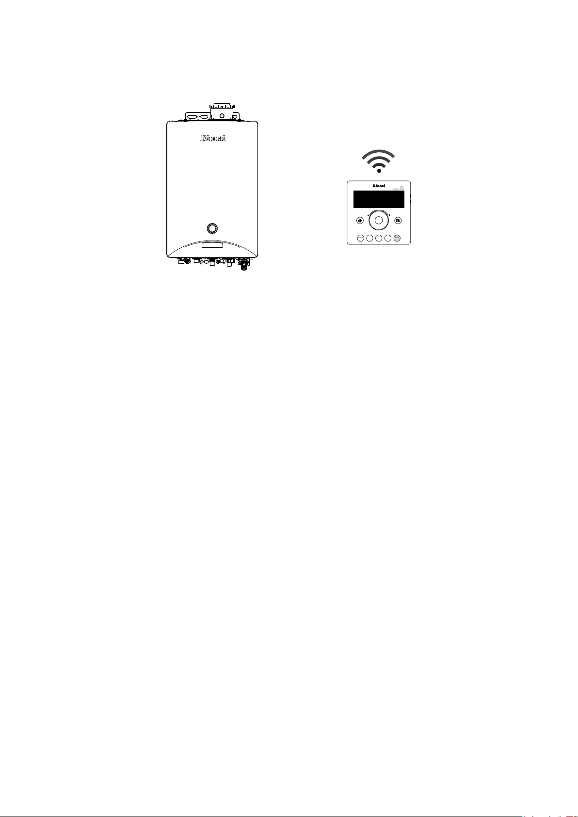
1.1 FEATURES AND BENEFITS
Congratulations on purchasing the CONDENSING gas boiler Rinnai, with ADJUSTABLE POWER (RANGE RATED),
sealed chamber and forced ow, with ELECTRONIC CONTROL OF TEMPERATURE and WiFi ROOM THERMOSTAT.
PUSH
AUTO ON
ENERGY
MENU
TIMER
SAVE
MONITOR
OFF
Zen is a PREMIXED boiler with “CONTINUOUS MODULATION ON GAS AND AIR”. It is equipped with a LOW NOx
EMISSION metal ber burner: the emission values make it one of the most environmentally friendly products on the
market.
The Rinnai Zen boiler is a FORCED FLOW gas appliance, with HIGH ENERGY EFFICIENCY: these features make it
extremely compact, guaranteeing considerable space savings and drastically reducing gas consumption.
The Zen ‘I’ range is supplied with a WiFi ROOMTHERMOSTAT as a standard, showing the operating temperatures
(heating and DHW), error codes and the advanced boiler regulation functions. By activating the WiFi FUNCTION
and installing the application ‘My Rinnai’ it is possible to control and manage the main functions directly through
your SMARTPHONE. The application allows the installation up to a maximum of ten users per command and the
management of three dierent boilers: the whole family can enjoy maximum comfort and it is also possible to manage
the boiler of a second home or of the elderly, inexperienced parents.
THE NOISE DURING OPERATION IS EXTREMELY LOW.
The Zen serie is equipped with a CONDENSATE TRAP SIPHON FILLED WITH A NEUTRALIZER: you can waste
condensate, moderately acidic and corrosive, without fear of damaging the drain or the disposal plant.
It is equipped with a SAFETY SENSOR FOR EARTHQUAKES: in case of medium or high sismic events, the boiler
automatically isolates itself from the gas plant, thus limiting gas leaks, explosions or res, which can make the
environment aected by earthquake further dangerous.
The Zen serie is equipped with a PRE-INSTALLED CLIMATIC PROBE. It is no longer necessary to work hard to
install the external temperature sensor: the probe is already connected and installed, ready for use. By activating
the ‘automatic operation’, the boiler will adjust its combustion based on the external ambient temperatures, always
guaranteeing excellent comfort and reducing fuel consumption and waste. As an optional element it is however
possible to install a specic extension probe for outdoor environments.
With Rinnai’s Zen boiler, You will NEVER BE WITHOUT HOT WATER: as long as electricity, water and gas are
guaranteed, hot water is available every time a hot water tap opens.
Hot water is exclusively produced in an INSTANTANEOUS way: it is not stored in tanks with limited capacity, always
source of constant dispersions and high energy consumption.
The appliance is equipped with a special safety and comfort function that CONTROLS THE MAXIMUM TEMPERATURE
of the hot water supplied. The temperature can be adjusted to a precise value: this function is particularly useful when
the appliance is installed at the service of children, patients or elderly people. If necessary, the temperature can be
modied at will from the control panel (remote control), supplied as standard, to better serve the user. The temperature
of the hot water supplied is constantly monitored by several internal sensors.
ERROR CODES are displayed on the remote control to facilitate technical assistance: they appear as ashing numeric
codes on the display.
The range of Zen boiler has an ‘IP 5’ PROTECTION RATE and can be freely installed in EXTERNAL ENVIRONMENTS,
directly exposed to atmospheric agents without particular protection (the correct installation of the ue gas tting is
necessary).
ANTIFROST PROTECTION is included as standard on each model: the appliance is protected up to -20°C.
8
1.2 IMPORTANT SAFETY INFORMATION
IMPORTANT
ATTENTION
WARNING
NOTE
IMPORTANT
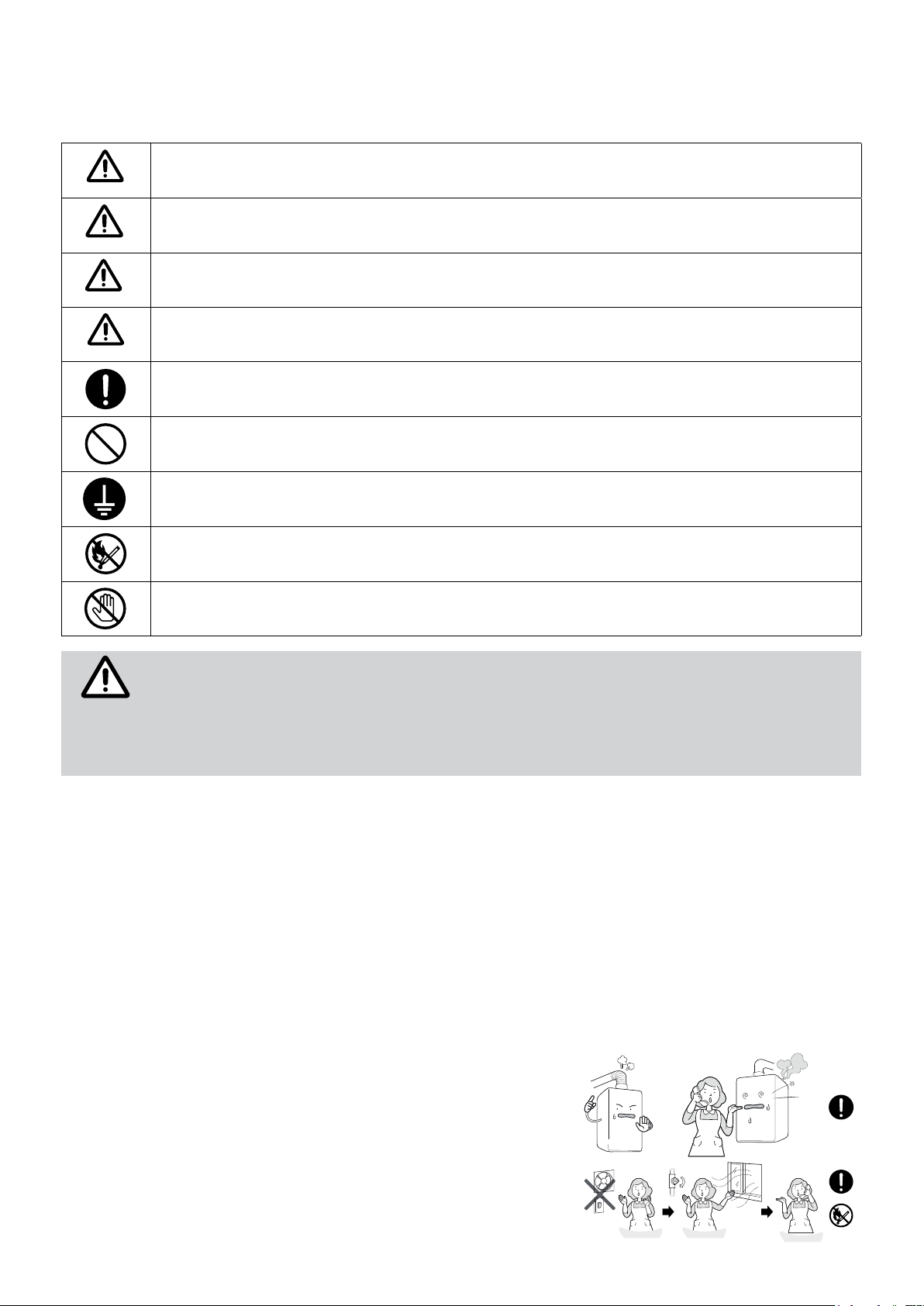
Meaning of the symbols used in the manual for important information concerning your safety:
Indicates a situation of potential serious danger, to respect and follow carefully.
Indicates a potentially hazardous situation which, if not avoided, may lead to injury or property damage.
Indicates an important information.
Information on the correct use, installation and operation of the product.
Indicates a potential condition of serious danger which must be complied.
Indicates a condition which should be avoided.
Indicates a ground connection for the prevention of an electric shock.
Warns of a risk of re. Keep the area clean and free from ammable materials.
Warns of a risk of injury or property damage when contacting.
The appliance must be installed by qualied personnel only.
It is possible to install Zen boilers in outdoor areas, always open-air and well ventilated, or in
partially protected areas (not exposed to direct atmospheric precipitation).
It is always mandatory to install an approved exhaust system.
Use the appliance exclusively for the use for which it was designed.
Rinnai boilers from the Zen range have been designed for wall installations only. They are built for domestic or similar
uses, for the production of domestic hot water and the heating of water at a temperature lower than that of boiling
at atmospheric pressure. They must be electrically powered, connected to a gas, heating and a domestic hot water
distribution system suited to their performance and power
Only a professional licensed company is authorized to install Rinnai gas appliances. The installation must follow
the requirements of the UNI and CEI Standards, current legislation and local technical regulations, according to the
indications of good technique.
Do not make any changes to the appliance: do not attempt to repair, replace components, open sealed parts or
disassemble the appliance. Any tampering can lead to risks to health, damage to property, compromise the safety and
proper functioning of the product: for any type of repair, modication of settings or maintenance of the product and its
accessories, we recommend contacting the Rinnai technical service center.
Use only original Rinnai parts.
If you notice unusual noises, smells or vibrations, stop the appliance
immediately and contact the Rinnai technical service company.
If you smell gas:
In the event of an earthquake, re, gas leaks, noises, stop the gas and
electricity supply and open doors and windows.
- close the main gas tap;
- open doors and windows to ventilate the room;
- contact Your technician and wait outside the house.
9
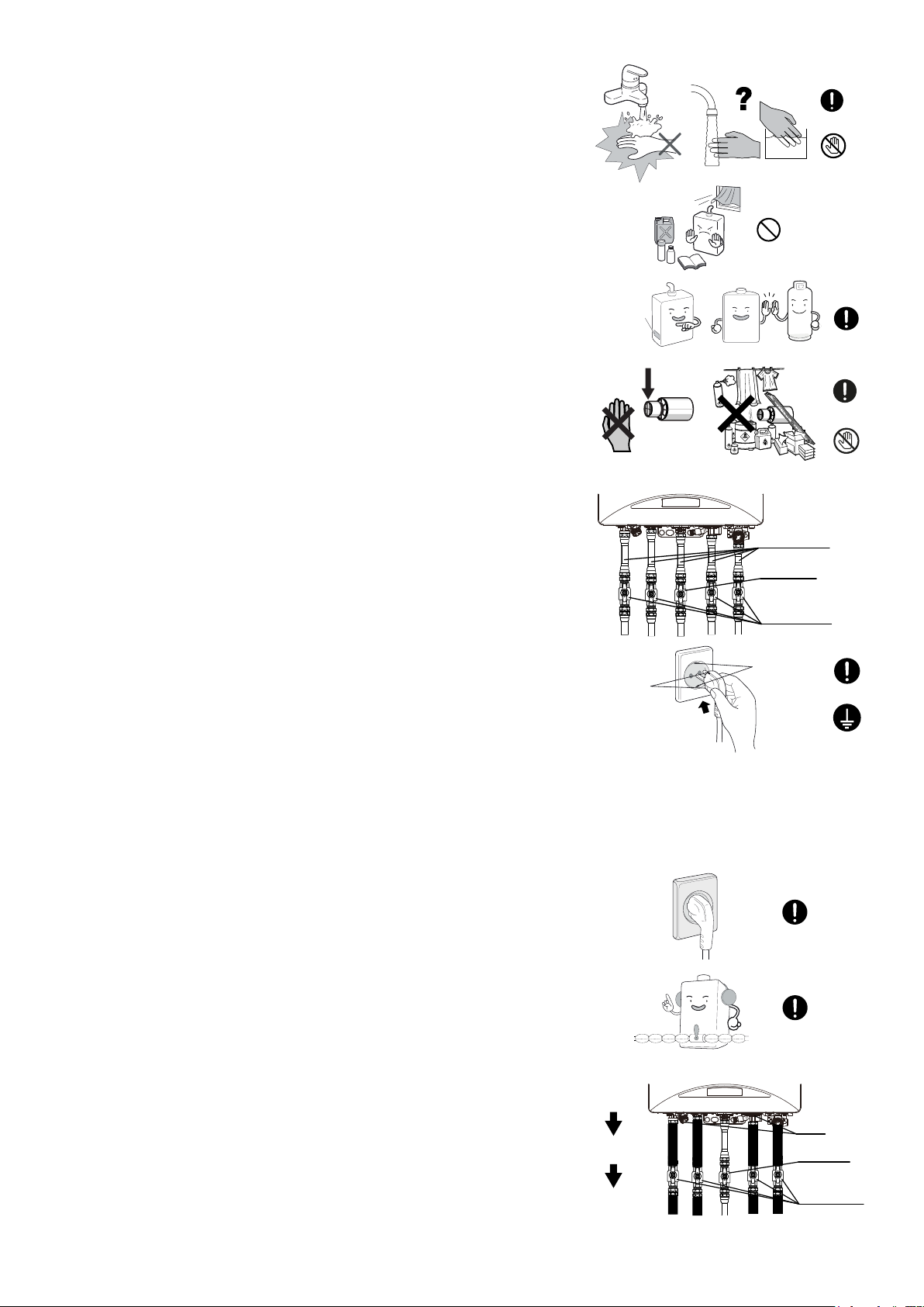
HOT!
Data plate
Water temperature over 50°C can cause severe burns instantly or even
death from scalding. Hot water at 60°C can severely burn a child in less than
a second. At 50°C it takes ve minutes. Always test the temperature of the
water before any use. To prevent these risks, Rinnai reccomends to consider
setting your hot water production at a maximum temperature of 50°C.
Do not store ammable objects near the appliance: it could cause a product
failure or re. Do not spray aerosols in the vicinity of this appliance while it
is in operation.
Check that the appliance is supplied with the correct gas type and pressure
according to the data plate: ensure that the gas in use matches with the gas
indicated on the data plate. If not, there could be incomplete burning of the
gas, resulting in toxic emissions and/or product failure.
Do not insert objects into the ue outlet. Do not spray water directly into the
ue outlet. Keep, trees, shrubs, etc. well clear of the ue outlet. On colder
days steam may discharged from the ue outlet. This condition is normal for
high eciency appliances and does not indicate a fault.
Do not touch the unit cover or the ue outlet.
Verify that the main gas tap is open before using the product.
It is recommended to use exible metal ttings, specic for gas (and water),
in the appliance connections to the gas (water) network. Avoid using rubber
ttings that may deteriorate early.
Insert valves on the gas and on the water pipes to facilitate any maintenance
and safety in emergencies.
HOT
Flexible fitting
Gas valve
Before connecting the mains cable, check that the power supply is suitable:
make sure that the electrical system is up to standard and has a good earth
Water valve
connection; otherwise the appliance may be damaged or malfunctioning.
It is not recommended to extend the supplied electrical cable (eg through the
use of extension cords or multiple sockets). In case of damage, replace the
Grounding
Grounding
electric cable with an original one. Replacement may only be performed by
Rinnai authorized technical personnel.
After installation (or long periods of inactivity) it is advisable to let the hot
water run before the use.
It is recommended the installation of a system to collect and drain water under the appliance in the case of water
leakage to prevent material and property damages.
Frost protection: Make sure that the power cord of the appliance is
plugged-in and the electrical power is always available.
The frost protection system activates only when the appliance is electrically
powered.
All pipes must be wrapped with insulating materials to prevent heat loss.
The thickness of insulation should be between 25mm and 50mm according
to outdoor temperatures. Electrical hot wires could be installed to protect
pipework subjected to extreme cold or wind chill conditions. Hot wire use is
recommended if the case of temperature drops below -15°C.
If extremely freezing conditions are expected, turn o water and gas, and
drain all water from the appliance. If power and the automatic frost protection
are connected, freezing will be prevented. (Anti-frost protection is tted as
standard equipment on all hot water units)
If water pipes are frozen, there would not be water ow in the system. Use a
heat source (e.g. hair dryer) to unfreeze the frozen components and pipes.
Before using the appliance after defrosting contact the Rinnai service to
verify possible damages.
10
1. Turn water
valve off
2. Turn gas
valve off
3. Drain
appliance
Filters
Gas valve
Water valve
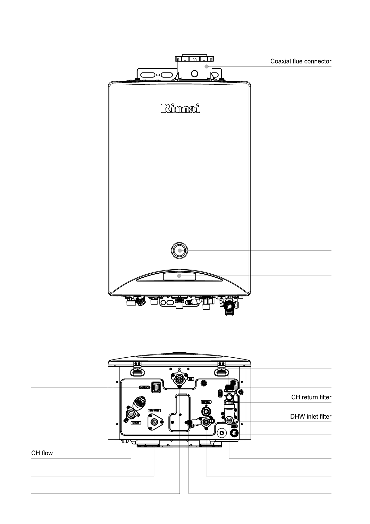
1.3 MAIN COMPONENTS
Emergency mode switch
Manometer CH circuit
Body controller
Pressure relief valve
Wiring access
DHW outlet
Gas
Condensate drainage
CH return
DHW inlet
Water supply valve / CH
11

Wi-Fi REMOTE CONTROLLER
Heating mode change
Adjust dial
Heating mode (CH)
Set
Hot water mode (DHW)
Auto / Save mode
Menu mode
Reservation mode
Anti-freezing function operation
Space heating mode
Wi-Fi connection
Eco mode operation
Auto mode operation
Save mode operation
PUSH
AUTO ON
SAVE
MENU
TIMER
ENERGY
MONITOR
OFF
Power / Child lock
Energy monitor mode
Burner ON
Flow temperature mode
Menu mode
Energy monitor
Heating temperature
Reservation mode operation
Reservation setting
Hot water temperature
Child lock operation
Time
BODY CONTROLLER
Burner lamp
Hot water mode (DHW) / Temperature control
Heating mode (CH) / Temperature control Hot water mode (DHW) lamp
Heating mode (CH) lamp
Heating (CH) / Hot water (DHW) temperature
12
1.4 OPERATION
IMPORTANT
Before to use the boiler, it is advisable to know how it properly works.
The operation of the boiler and the main functions that can be activated are described below.
Before using the boiler, make sure that the heating circuit is always lled correctly: when the
system is still cold, the pressure gauge on the front panel must indicate a value in the green
sector (0.5 ÷ 1.5bar). If necessary, restore the correct value by operating the ll/load tap at the
base of the boiler.
When the boiler is electrically connected, an automatic venting program is activated. It can
last from 60 to 120 minutes depending on the system. It is necessary to wait until the end of
the cycle to allow the expulsion of all the air that was formed in the installation phase (or in the
period of non-use). Press a button on the remote control causes the early stop of the venting
cycle and can cause problems. A particular noise can be a sign of the presence of air bubbles
still circulating in the pipes: unplug the boiler and re-plug it to repeat the venting cycle.
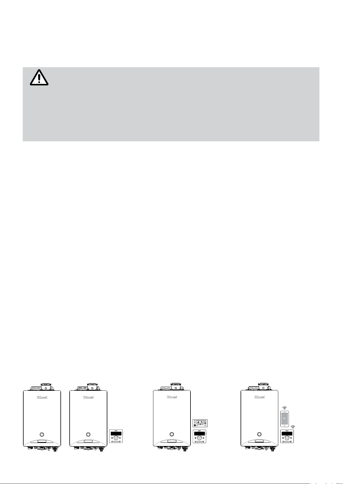
The boiler is ready for the use and a wireless chronothermostat is supplied as a standard. The command is pre-set
to control the ‘heating temperature’ of the system. To operate, the command must remain connected by cable to the
boiler: in case of remote installation it is possible to extend the electrical cable paying particular attention to use a
shielded cable in case it is positioned in the vicinity of high voltage electrical wiring.
The Rinnai condensing boiler can operate without the remote control connected: operated only by the control panel,
which is pre-assembled on the boiler (body controller). This basic conguration allows to:
activate/deactivate the heating mode and adjust the ow temperature of the heating system;
•
activate/deactivate the hot water supply, adjusting the temperature of the hot water;
•
check for malfunctions and error codes.
•
A second operation mode is by connecting the Rinnai WiFi chronothermostat, which is supplied as a standard with the
appliance. The main features available are:
select the heating mode (room temperature or ow temperature mode);
•
activate/deactivate the heating mode and adjust the ow temperature of the heating system;
•
activate/deactivate the hot water supply, adjusting the temperature of the hot water;
•
special functions use (fast heating; hot water pre-heat; Auto mode, Save, Reservation, etc);
•
check for malfunctions and error codes;
•
monitor the energy consumption;
•
adjustment of boiler’s operation parameters;
•
operation of the boiler through the ‘My Rinnai’ app and Your own samrtphone.
•
A third operation mode is made by connecting the boiler a third party thermostat in conjunction to the Rinnai WiFi one:
in this conguration the Rinnai remote is no more controlling the room temperature, but it can be still used to adjust the
hot water temperature. The third party thermostat is in control of the room heating temperature.
By activating the WiFi mode, the boiler can be operated and programmed by Your own Smartphone through the ‘My
Rinnai’ application (up to ten users can register and control the boiler). The main functions are all available and always
handy; more advanced and more specic ones are available, to manage and program the boiler. The application is
equipped with a simple introductory guide that explains its operation quickly and easy. The specic user manual for
the application is available on the Internet site: www.rinnai.it
Body controller,
WiFi room-thermostat
Body controller,
WiFi Rinnai control &
third party room
thermostat
Body controller &
WiFi room-thermostat
& Smartphone
Body controller
AUTO ON
MENU
SAVE
PUSH
ENERGY
TIMER
MONITOR
OFF
AUTO ON
MENU
SAVE
PUSH
ENERGY
TIMER
MONITOR
OFF
AUTO ON
MENU
SAVE
PUSH
ENERGY
TIMER
MONITOR
OFF
13
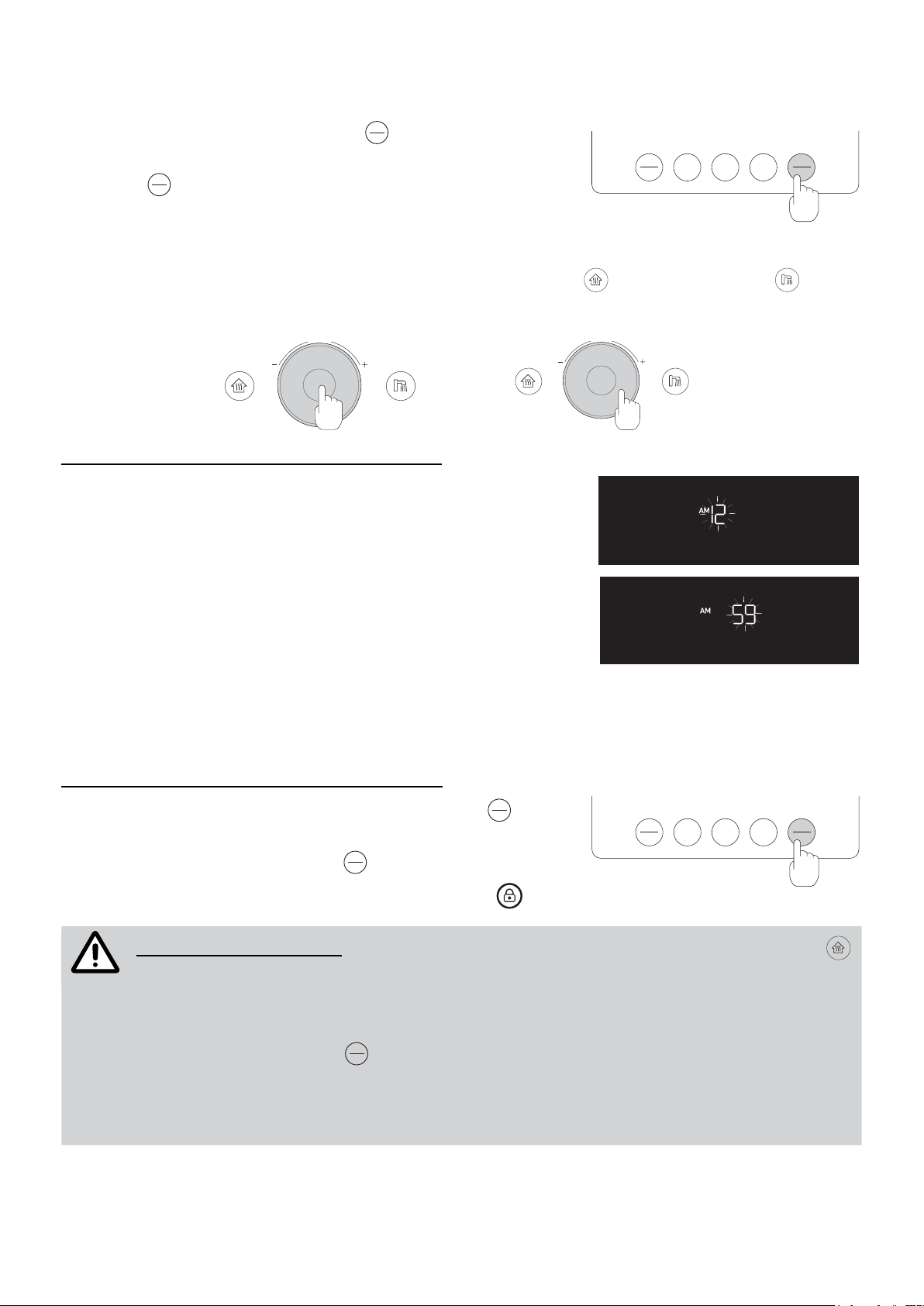
1.4.1 INITIAL SETTINGS
NOTE
Turn the boiler On/Off
ON
When rst operated, by pressing the button
OFF
(1) on the WiFi thermostat:
the display lights up, the ‘clock’ ashes and the boiler can now operate.
ON
If the button
OFF
is pressed during the boiler’s operation, the display turns o
and the boiler stops operating.
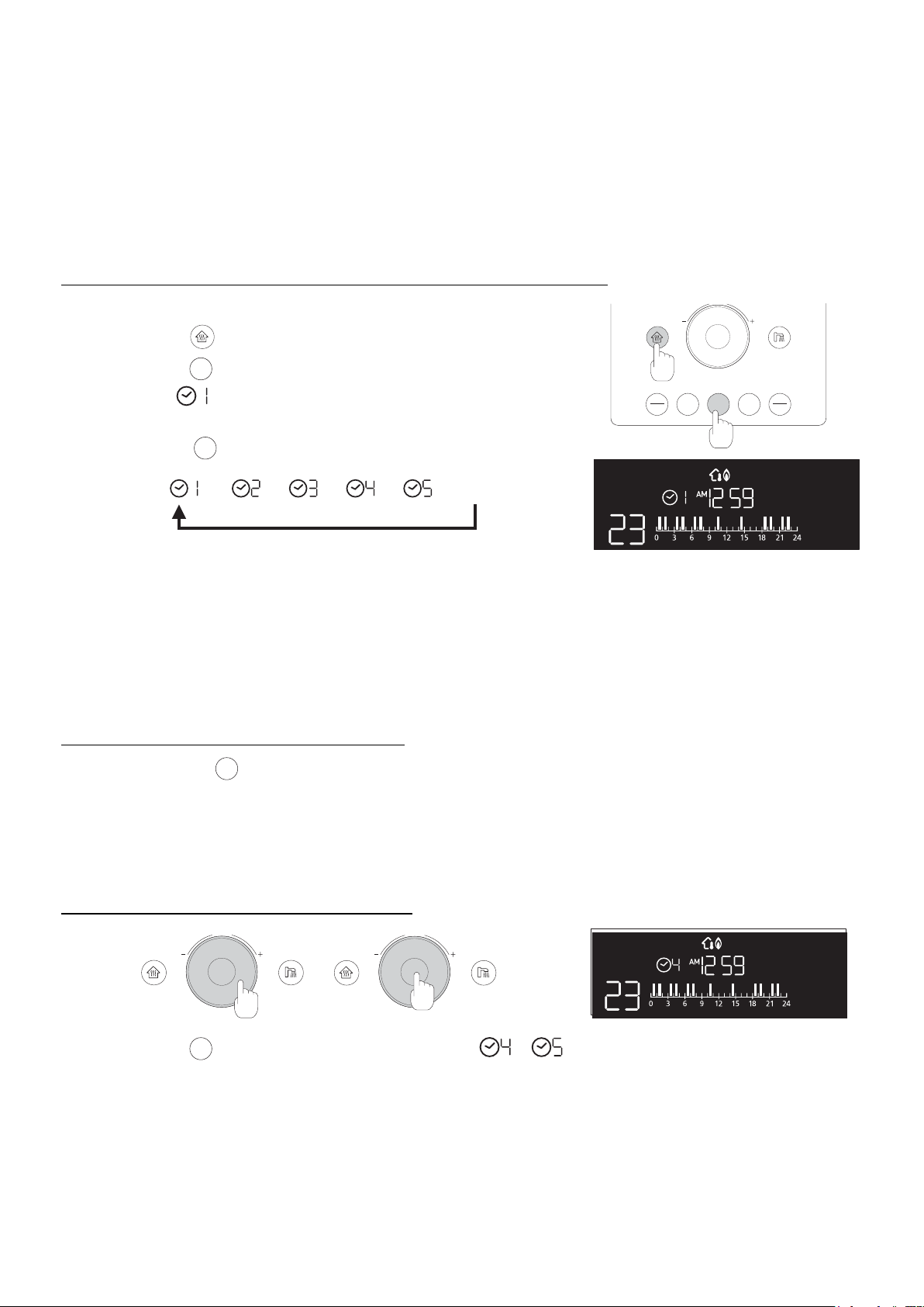
Time setting
AUTO ON
MENU
SAVE
TIMER
ENERGY
MONITOR
OFF
1
It is possible to adjust the ‘time’ only when main functions (central heating
and hot water heating ) are not
activated: check that their icons, on the sides of the adjusting dial, are not lighted. If they are lighted, it is necessary to
deactivate the function by pressing the icon on the panel.
PUSH
1
PUSH
2
To set the time on the WiFi remote follow the procedure:
Press and keep pressed for three seconds the adjusting dial (1):
•
a ‘beep’ is heard and the ‘hour’ ashes;
Rotate the knob to set the desired hour (2);
•
To conrm the hour, press once the knob (1):
•
a ‘beep’ is heard and the ‘minute’ ashes;
Rotate the knob to set the desired minute (2);
•
Press the knob once to conrm the time set (1):
•
a ‘beep’ is heard and the ‘time’ is set.
‘Child-lock’ function
To prevent tampering and to increase the security, the WiFi thermostat is equipped with a ‘key lock’ function.
To activate the ‘Child-lock’ function follow the procedure:
ON
Ensure the thermostat is switched On (press the button
•
it On);
ON
Press and keep pressed the button
•
OFF
(1) for three seconds:
a voice prompt is heard and the display shows the icon
OFF
to switch
;
AUTO ON
MENU
SAVE
TIMER
ENERGY
MONITOR
To deactivate the lock function it is possible to follow the locking procedure or to keep the heating key
pressed for three seconds.
When the key lock function is active:
the icon shown on the display ashes when the keys of the thermostat are pressed;
•
ON
by pressing the button
•
in the case of malfunction, to reset the error code ashing on the display, it is necessary to
•
OFF
the thermostat will not switch O;
unlock the thermostat rst;
the lock function is active on the WiFi remote only: the body controller will not be locked.
•
OFF
1
14
1.4.2 HEATING FUNCTION (CH
NOTE
The heating function will also be mentioned as CH.
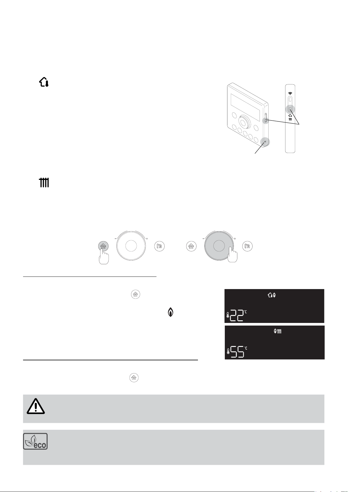
Using the Rinnai WiFi roomthermostat, it is possible to choose between one of the two heating modes: by pressing
the button of g.1, on the right side of the WiFi thermostat, You select the desired heating mode and the relevant
symbol appears on the display. To change the heating mode, it is necessary that the heating function is deactivated
(the display must appear empty).
)
•
the Rinnai remote control is equipped with a temperature sensor that
constantly monitors the temperature of the environment in which it is
installed.
The boiler mantain the room heated according to the temperature set on the
remote control: when the temperature detected in the room is higher/lower
than the set temperature, the boiler stops/activates accordingly. The preset
temperature is 22°C; it is possible to select temperatures ranging from 5°C
to 40°C.
The room thermostat should be installed in a signicative room for the home.
’Space-heating’ mode:
Room
temperature
sensor
Heating
mode
button
Fig.1
•
the Rinnai remote control allows you to adjust the ow temperature of the heating system. When the measured
temperature is higher/lower than the set temperature, the boiler stops/activates accordingly. The preset temperature
is 55°C; it is possible to select temperatures ranging from 35°C to 80°C.
Heating temperature setting
’Flow-heating’ mode (default setting):
PUSH PUSH
1
To set the heating temperature follow the procedure:
Press once the heating mode button (1):
•
a ‘beep’ is heard and the button
temperature value previously selected is ashing;
the boiler res and the display shows the icon
burner is on;
when the set temperature is achieved, the boiler switches the burner
o and the icon of the ame is no more displayed.
Rotate the adjusting dial (2) to modify the desired set temperature.
•
To deactivate the heating function of the boiler follow the procedure:
Press once the heating mode button (1):
•
a ‘beep’ is heard and the button
value.
To verify the real water delivery temperature of the heating system (this may dier from the set temperature)
it is necessary to keep the thermostat knob pressed for three seconds: the display shows the real value for
ten seconds and then returns to normal display.
lights up; on the display the
as soon as the
turns o; the display does not show anymore the heating temperature
2
During normal operation, the boiler can operate at a pre-set regime which is particularly favorable
for the reduction of polluting emissions and fuel consumption; during this operation the boiler
operates at its maximum energy eciency and the green “Eco” symbol shown on the side appears
on the display.
15
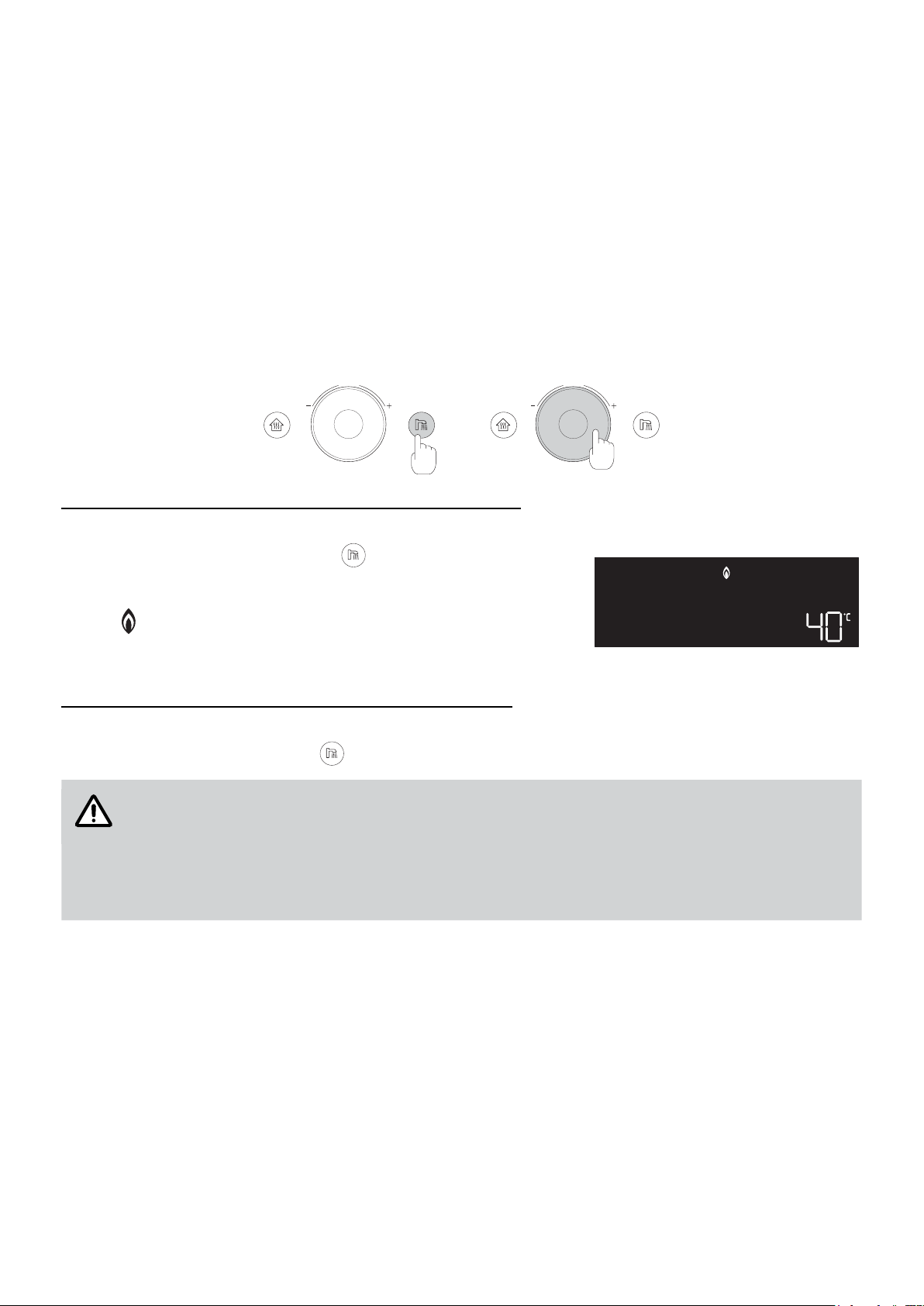
1.4.3 DOMESTIC HOT WATER FUNCTION (DHW
PUSH PUSH
ATTENTION
The hot water function will also be mentioned as DHW.
The production of hot water takes place in a direct and instantaneous way: you will never be without hot water as long
as electric power, water and gas are guaranteed.
The appliance is equipped with a sensor that keeps the temperature of the supplied water under control: this is source
of high comfort and extreme safety for every type of user.
It is always possible to activate the heating mode, during the hot water supply: this function will not be activated until
the production of domestic hot water is completed.
It is possible to keep both CH and DHW functions activated but the boiler always gives priority to the use of DHW
mode with respect to CH.
Hot water temperature setting
)
1
To activate and set the hot water temperature follow the procedure:
Press once the hot water mode button (1):
•
a ‘beep’ is heard and the icon
previously selected temperature value is ashing;
by opening a tap, the boiler res and the display shows the icon
as soon as the burner is on; the color of the hot water function
button’s led turns to orange.
Rotate the adjusting dial (2) to modify the desired temperature.
•
To deactivate the DHW function of the boiler follow the procedure:
Press once the hot water function button (1):
•
a ‘beep’ is heard and the icon
The selectable temperatures may vary between 35°C and 60°C.
For safety reasons, all the taps must be closed before a higher value than 55°C is set. Hot water
must not be used during the operation.
In order to reduce gas consumption and to extend the water heater’s life, Rinnai suggests to set
the device’s temperature on the minimum which is more suitable for the intended use. Use hot
water on the pre-set temperature, so there is no need to mix it with cold water.
lights up; on the display the
stops; the display does not show anymore the hot water temperature value.
2
16
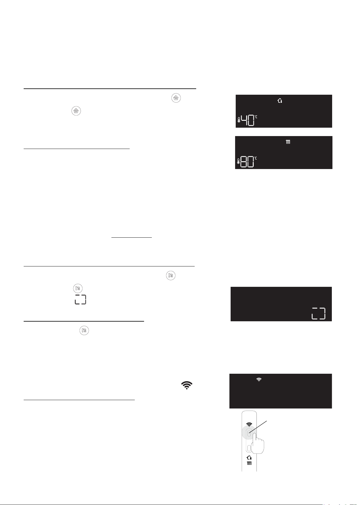
1.4.4 HOT WATER RAPID HEATING AND PRE-HEATING FUNCTION
Rapid heating
The rapid heating function can be used to quickly restore the suitable temperature in a cold environment: the boiler
will operate at maximum power for twenty-ve minutes, in order to create the right conditions for a sudden rise in
temperatures in the installation.
At the end of this time interval, the boiler will go automatically back to the pre-set functioning.
To activate the rapid heating function, perform the following steps:
Activate the heating mode, by pressing the button ;
•
Press again for three seconds:
•
the display will show a temperature of 40°C if the boiler is set on
the’room temperature’ mode; or 80°C if the boiler is set on the ‘ow
temperature’ mode.
To deactivate the rapid heating function:
Turn the dial.
•
Hot water pre-heating function
Ambient temperature mode
Flow temperature mode
The pre-heating function consents to prepare the boiler for the provision of domestic hot water and to benet of a
superior comfort: pre-heat function allows a faster delivery of hot water at the desired temperature shortening the time
needed for its production.
When the function is activated, the hot water preparing circuit is immediately raised to the right temperature and
mantained hot for thirty minutes (or until rst use).
At the end of this time period (or after having used hot water), the boiler stops this function automatically in order to
reduce wasted energy and minimize the consumption, then returns to normal operation.
To activate the hot water pre-heating mode, follow the procedure:
Activate the DHW mode, by pressing the button ;
•
Press again for three seconds:
•
the symbol
hot water temperature set before.
To deactivate the hot water pre-heating mode:
hold the button pressed for three seconds.
•
1.4.5 WIFI FUNCTIONS
It is possible to control the boiler through smartphone, by installing the free App ‘My Rinnai’ and registering the supplied
WiFi chronothermostat: the information about the proper installation procedure are provided in the specic paragraph
in the end of this handbook .
(in motion) will appear on the display, replacing the
When the WiFi is on, this symbol will appear on the display
To activate or deactivate the WiFi function:
Press the button (1) on the remote control’s side.
•
WiFi function key
1
17
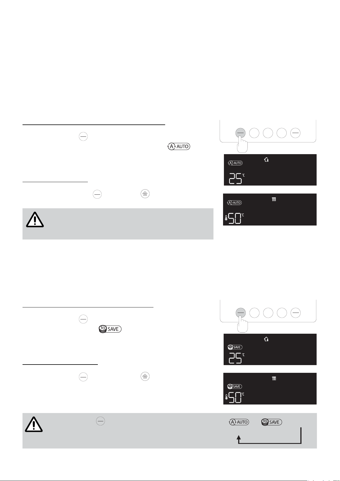
1.4.6 AUTO MODE (AUTO
NOTE
NOTE
)
Auto mode will be also indicated by the abbreviation AUTO.
The AUTO mode enables the boiler to adapt the regular ow temperature of the heating circuit to the values of the
outdoor ambient temperature, in complete autonomy. The auto mode only works on the heating mode and not on the
production of hot domestic water.
The device periodically monitors the external temperature in order to adjust the internal ow temperature by means of
a sensor: in the cold seasons, the boiler will be able to adjust the heating circuit’s water’s temperature proportionally to
the outdoor temperature reduction; the other way round, the boiler will lower the indoor temperature to adjust it to the
rising outdoor temperature in the warmer seasons.
The device works autonomously, adjusting its own functioning to the actual temperatures of the current season. This
provides a greater domestic comfort while reducing polluting emissions and fuel consumption.
To activate the AUTO mode, perform the following steps.:
Press the button
•
AUTO
on the room-thermostat once (1):
SAVE
a light blue symbol will appear on the display
and the
AUTO ON
MENU
SAVE
1
TIMER
ENERGY
MONITOR
OFF
function is activated;
if the heating mode is active, the display will appear as shown in the
gure on the right;
To leave the AUTO mode:
Room temperature mode
Press once the button
•
AUTO
, or the button .
SAVE
When AUTO mode is on, the boiler will not consent you
to modify the heating temperature: this value is entirely
automatically managed. AUTO mode has to be disabled to
Flow temperature mode
change the temperature.
1.4.6 ENERGY-SAVING MODE (SAVE
)
Energy-save mode will also be mentioned as SAVE.
Energy-saving mode exclusively operates on the heating mode and not on the domestic hot water production. When
the SAVE mode is on, the boiler modies the on/o operation of the burner. The dierent temperatures that is possible
to set with the chronothermostat are limited (in order to reduce energy consumption). So the maximum selectable
room temperature shall be 20°C and the maximum ow temperature shall be limited to 60°C.
To activate SAVE mode, perform the following steps:
Press the button
•
the light blue symbol
AUTO
on the chronothermostat twice (1):
SAVE
will appear on the display and the
AUTO ON
MENU
SAVE
1
TIMER
ENERGY
MONITOR
OFF
mode will be activated;
if the heating mode is active, the display will appear as shown in the
gure on the right;
To deactivate the SAVE mode:
Room temperature mode
Press the button
•
AUTO
once, or the button .
SAVE
18
Press the button
AUTO
more than once and scroll through the
SAVE
AUTO and SAVE functions as shown in the scheme:
Flow temperature mode
► ► OFF
Mod. AUTO Mod. SAVE
1.4.7 RESERVATION MODE (RESERVATION
.
PUSH
)
The functioning of the ‘reservation mode’ will also be mentioned as RESERVATION.
The Rinnai Wi’s chronothermostat consents you to set time slots for the heating mode every day. It is possible to
program the favourite time slots during which the boiler must maintain a comfortable temperature and those during
which it is allowed to reduce the temperature (night time or whenever nobody is at home).
The specic time reservation works both in ‘room temperature’ mode and in ‘ow temperature’ mode and works
exclusively on the heating mode but not on the domestic hot water production.
To activate and program the RESERVATION mode, perform the following steps.:
set the intended time on the chronothermostat (see par. 1.4.1)
•
Press button (1);
•
Press button
•
the icon
TIMER
once(2):
ashes on the display, meaning that the specic time
program nr.1 of the RESERVATION mode has been activated;
Press button
•
TIMER
several times to select the intended time slot:
1
AUTO ON
MENU
SAVE
TIMER
ENERGY
MONITOR
2
OFF
► ► ► ► ►OFF
The programs from number one to three are predened and cannot
be modied, while the specic time programs number four and ve can be personalized;
to conrm the selection of the intended time in the program is sucient to wait a few seconds: the icon of the
•
intended specics time slots will stop blinking.
The specic time reservation will be completed by dening the temperatures T1 (daytime) and T2 (reduced) in
•
the menu A (parameters 6 and 7) of the chronothermostat functions (see par. 1.4.8):
the temperature T1 is used by the boiler during the intended and selcted specic times (highlighted in orange
in the time slot); but the temperature T2 is used during the unselected time slots.
To exit RESERVATION mode during the operation:
Press the button
•
TIMER
: the boiler will go back to normal operation.
By re-activating RESERVATION mode, the system will re-open the previously selected program.
Personalizing the reservation mode
Only the programs four and ve can be personalized. The use of ‘My Rinnai’ application allows to select a more
detailed time slots programming schedule.
To select the time slots, perform the following steps:
PUSH
1
Press button
•
Turn the dial (1) and drag the orange ashing selector of the hour bar on the intended time;
•
Press the dial (2) to conrm the selection of the intended time;
•
Repeat the previous operations util you have completed the intended pattern;
•
The reservation is completed when temperature T1 (daytime) e T2 (reduced) are dened in the menu A
•
TIMER
until it is possible to select a program
PUSH
2
o
.
;
.
(parametres 6 and 7) of the thermostat functions (see par. 1.4.8):
the boiler uses temperature T1 in correspondence to the selected time slots (highlighted in orange in the time
schedule); the temperature T2 is used during the unselected time slots.
19
1.4.8 PARAMETERS MENU
IMPORTANT
NOTE
Rinnai WiFi chronothermostat allows the user to benet from a great variety of parameters related to the boiler
functioning. It provides precious information to understand eventual problems in the appliance’s operation.
For safety reasons, Rinnai suggests not to modify the parameter menus without having fully
understood the meaning of the parameters themselves and their possible consequences on the
boiler.
It is recommended to call the enterprise (Rinnai Italia) in advance, in order to not damage the boiler
or the installation which is connected to it and to avoid all the possible risks for the customers.
Parameters are grouped by typology and sub-divided in sub-menus:
Menu A Boiler and thermostat settings
A ► B ► C ► D ► Exit
Menu B Services and maintenance
Menu C Faulty History Mode
Menu D Information
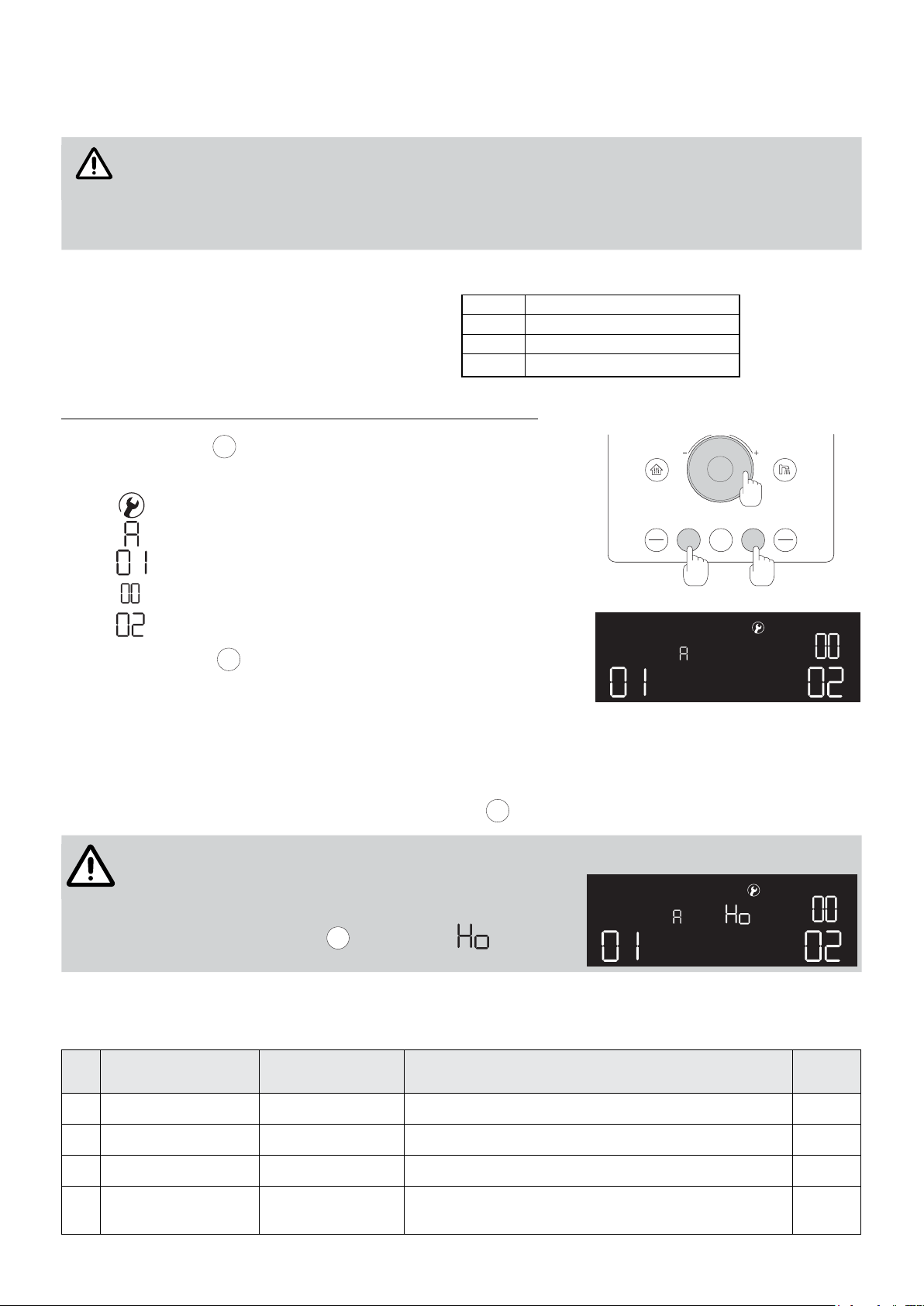
To enter and select the parameters menu, perform the following steps:
press the button
•
the following icons will appear on the WiFi chronothermostat:
•
MENU
(1);
PUSH
2
- means that you have entered in the parameters menu;
- indicates the selected menu: ‘menu A’;
- indicates the visualized parameters: ‘parameter 01’;
AUTO ON
MENU
SAVE
1 3
TIMER
ENERGY
MONITOR
OFF
- indicates the value of the visualized parameters: ‘02’.
press the button
•
MENU
several times to change menu:
the A menu and the B menu are accessible only if the heating
(CH) and hot water (DHW) functions are deactivated.
By turning the dial (2) it is possible to change the parameter (or its value): the icon will be lit up.
By pressing the dial (2) it is possible to conrm the selection of the parameter (or its value): the icon is not blinking.
MENU
To exit the parameters menu is necessary to press the button
(1) more than once.
After 20 seconds of inaction, the parameters menu will be
automatically closed and the display will go back to its
normal operating state.
Not to exit the parameters menu and to keep it forced active
ENERGY
(for ve minutes), press
MONITOR
: the symbol (hold) will
show up on the display.
Parameters of A menu
The A menu groups all the parameters concerning the thermostat settings and the boiler programming:
Nr
par.
Parameter Values Parameter's description
1 Thermostat language EN, IT, ES EN: English; IT: Italian; ES: Spanish. EN
2 Loudspeaker volume 0~5 (OFF, 1~5) Modies the volume of the vocal messages of the thermostat. 3
3 Keyboard sounds ON/OFF Activates or deactivates the sounds of the buttons. ON
4 Antifreeze signal / errors ON/OFF
Acustic alarm protectioning notications for antifrost and boiler
functioning errors.
20
Initial
value
ON

Nr
External temperature (°C)
Flow temperature (°C)
30
35
40
45
50
55
60
65
70
75
80
85
-30 -25 -20 -15 -10 -5 0 5 10 15 20
1
2
3
4
5
par.
Parameter Values Description parameter
5 Led brightness 1~3 Modies the brightness of led CH e DHW. 2
Initial
Value
Temperature T1
6
(daytime)
Temperatura T2
7
(reduced)
Limit of maximum
8
discharge temperature
35~80°C
5~40°C
35~80°C
5~40°C
35~80°C
Programming of daytime temperature of thermostat.
Programming of reduced temperature of thermostat.
Limits the max. ow temperature that the boiler can reach, in
every kind of functioning/mode/function.
9 Climatic curve 1~5 Activated during AUTO mode, selects the climatic curve. 4
Climatic curve
10
translation
Compensation temp.
11
chronothermostat
Compensation temp.
12
outer sensor
-10~10°C Transfers the values of the preselected climatic curve. 0°C
-10~10°C Modies the perceived temperature by the room thermostat. 0°C
-15~15°C
Modies the external temperature detected by an outer
sensor.
It enables the boiler to delay the ignition of the burner to
13 Burner ignition delay OFF, 1~50
a max. of 500 seconds on installation with slow peculiar
commutational elements (local valves).
Value x10 = delay
Frequence
14
re-ignition CH
Positioning of the
15
climatic sensor
1~5
OU/In
Modies the 'OFF forced stationary' state of the burner,
between two consecutive ignitions.
Low value = longer waiting time
Denes the environment in which the climatic sensor has been
installed: the sensor is pre-installed in the boiler (In), but it can
be extended outside (OU).
In 'room temperature' mode, the ow temperature of the boiler
Booster of delayed
16
temperature CH
ON/OFF
changes when the dierences between the pre-set temperature
and the temperature detected by the thermostat changes.
with this parameter, the ow temperature is incremented with
respect to its normal value.
Reset parameters
0
menu A
- -
The A menu's parameters are brought back to the initial
settings.
75°C
21°C
55°C
16°C
80°C
0°C
OFF
5
In
OFF
- -
Climatic curves
The climatic curves (numbered from one to ve), concerning parameter 9 from A menu are shown below:
21
 Loading...