

Rinnai Ember Series, RDV600N, RDV700N, RDV700L, RDV600L Installation Manual
Installation guide
Ember
Models: RDV600N/RDV600L
RDV700N/RDV700L

Important:
Appliance must be installed with a Rinnai approved flue
system.
This appliance shall be installed in accordance with:
- Manufacturer’s installation instructions
- AS/NZS 5601 Gas Installations
Installation, servicing and repair shall be carried out only
by authorised personnel.
Warning
Improper installation, adjustment, alteration, service or
maintenance can cause property damage, personal injury
or loss of life.
For more information about buying, using,
and servicing of Rinnai appliances call:
0800 RINNAI (0800 746 624).
Rinnai New Zealand Limited
105 Pavilion Drive, Mangere, Auckland
PO Box 53177, Auckland Airport, Auckland 2150
Phone: (09) 257 3800
Email: info@rinnai.co.nz
Web: www.rinnai.co.nz
www.youtube.com/rinnainz
www.facebook.com/rinnainz
cnt:
Before you start .......................................................... 4
Ember specification ...................................................5
Dimensions .................................................................6
Gas and electrical supply ............................................ 8
Enclosure dimensions ................................................9
Clearances from combustibles ................................... 10
TV installation .............................................................12
Ember masonry installation overview ........................14
Ember mock chimney installation overview .............. 16
Installing the zero clearance frame ............................18
Attaching the flexi flues to the spigot plate ...............19
Burn media installation ............................................... 20
Adding the glass and vermiculite ...............................21
Log set installation .....................................................22
Stone set installation ..................................................24
Commissioning ..........................................................26
Installing the frame.....................................................27
Test operation and lighting sequence ........................28
Installation checklist and customer handover ...........28
Wiring diagram ........................................................... 29
Ember flueing ............................................................. 30
Flueing options ...........................................................32
Horizontal terminations (mock chimney) .................. 33
Vertical terminations (mock chimney).......................34
Vertical termination (masonry chimney) ...................35
Horizontal termination (masonry chimney) ..............36
Flue kits and components ..........................................37
Ember specicationBefore you start
Unpack the appliance and components and check for damage. DO NOT install any damaged items.
Check all components have been supplied and that you have the correct gas type.
Read these instructions to get an overview of the steps required before starting the installation. Failure
to follow these instructions could cause a malfunction of the appliance. This could result in serious injury
and/or property damage.
Ensure the flue termination will meet the required flue clearances as shown in AS/NZS 5601.1 before
installation.
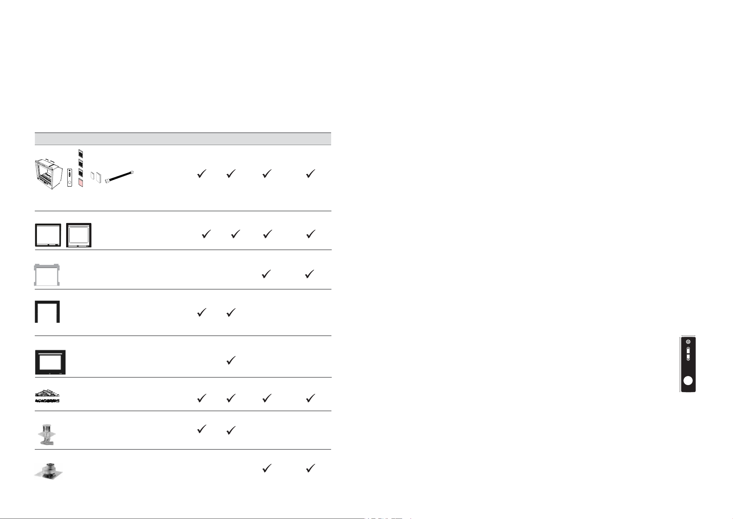
Item Masonry installation Mock chimney installation
Ember 600 Ember 700 Ember 600 Ember 700
Engine
The Ember engine comes with; remote control (batteries inserted), operation and installation guides, granule packs, rockwool,
crushed glass, vermiculite, and flexible gas connection.
4-sided or 3-sided frame
Zero clearance frame
A must-have for mock chimney installations as it
gives automatic clearances to combustibles and
is critical for keeping the installation square.
Infill panel (if needed)
Infill panel only needed if the cavity is slightly larger than the framepanel will cover the gap behind the fire and 3-sided frame.
700 Masonry frame
Wider masonry frame for the Ember 700,
designed to cover a larger cavity opening.
Burn media
Masonry flue components
Mock chimney flue components
Option of a log or stone setensure you
have the correct set before starting, they are
different for each model.
Flexi flue components for a vertical or
horizontal chimney termination
Flue components for a vertical or horizontal
termination.
Ember 600 specification summary
Input = 12-23 MJ/h
Output = 2.5-5.0* kW
Efficiency = 77% (on high)
Heating area = up to 85 m
2
**
Gas type = NG or ULPG
Ember 700 specification summary
Input = 14-27 MJ/h
Output = 3-6.0* kW
Efficiency = 77% (on high)
Heating area = up to 99 m
2
**
Gas type = NG or ULPG
A direct vent inbuilt gas fireplace with a glass front
and convection fan, pushing warm air from the
top of the appliance. Operated with an infra-red
remote control.
Different burn media and frame options available.
* Will vary according to gas type and flue configuration.
** Will vary depending on geographical location in NZ.
Suitability
Suitable for masonry installations and installations
into a mock chimney, in open plan areas and living
rooms.
Data plate
Located on the lower RHS of the base panel in
front of the gas control.
Convection fan
120 V AC 50 Hz 2-speed centrifugal blower.
Lighting
Halogen lamps 240 V 25 W x 2.
Gas connection
Brass ½ “ BSPT male fitting, the gas supply
terminates inside the heaterlower right hand
side of the appliance.
Ignition
230-240 V AC 50 Hz high voltage electronic spark
generation unit.
Installation considerations
Room sizesmaller rooms will heat up quickly,
and due to the efficiency of the appliance, the
Ember will turn to a low flame setting once the set
temperature has been reached.
For efficient performance Rinnai recommends
installing the fire as close to the floor as possible.
If the unit is installed higher up the wall the
movement of air from the convection fan,
depending on the room configuration, could
create draughts.
Noise level: 37-45 dB(A)
Flueing: Masonry
Colinear flexi flue, air intake Ø 75 mm, exhaust
Ø 100 mm. Appliance must be installed with a
Rinnai Ember flue system.
Flueing: Mock chimney
Colinear (air intake Ø 75 mm, exhaust Ø 100 mm)
to coaxial direct vent flueing (inner Ø 100 mm,
outer Ø 170 mm). Appliance must be installed with
a Rinnai Ember flue system.
Electrical
This heater has a 1.5 m power cord with a three pin
plug supplied. The power cord passes through a
slot in the back left hand corner of the appliance.
• High = 110 W
• Standby = <1W
Safety devices
Flame failure sensing system, pressure relief,
overheat safety switch, air temperature sensor,
thermal fuse, overcurrent fuse, and spark
detector.
Temperature control
34 mm
Once the unit is turned on the infra-red
remote* is used to control the flame
height and heat output.
136 mm
If the remote is not used the Ember will
automatically modulate between the
23
burner settings to maintain the default
set temperature of 22 °C.
* Temperature sensor is located in the bottom of the remote
depth - 11 mm
Weights
• Ember 600 = 51 kg
• Ember 700 = 55 kg
4 | Ember Installation Guide: 12890-B 02-18
Ember Installation Guide: 12890-B 02-18 | 5
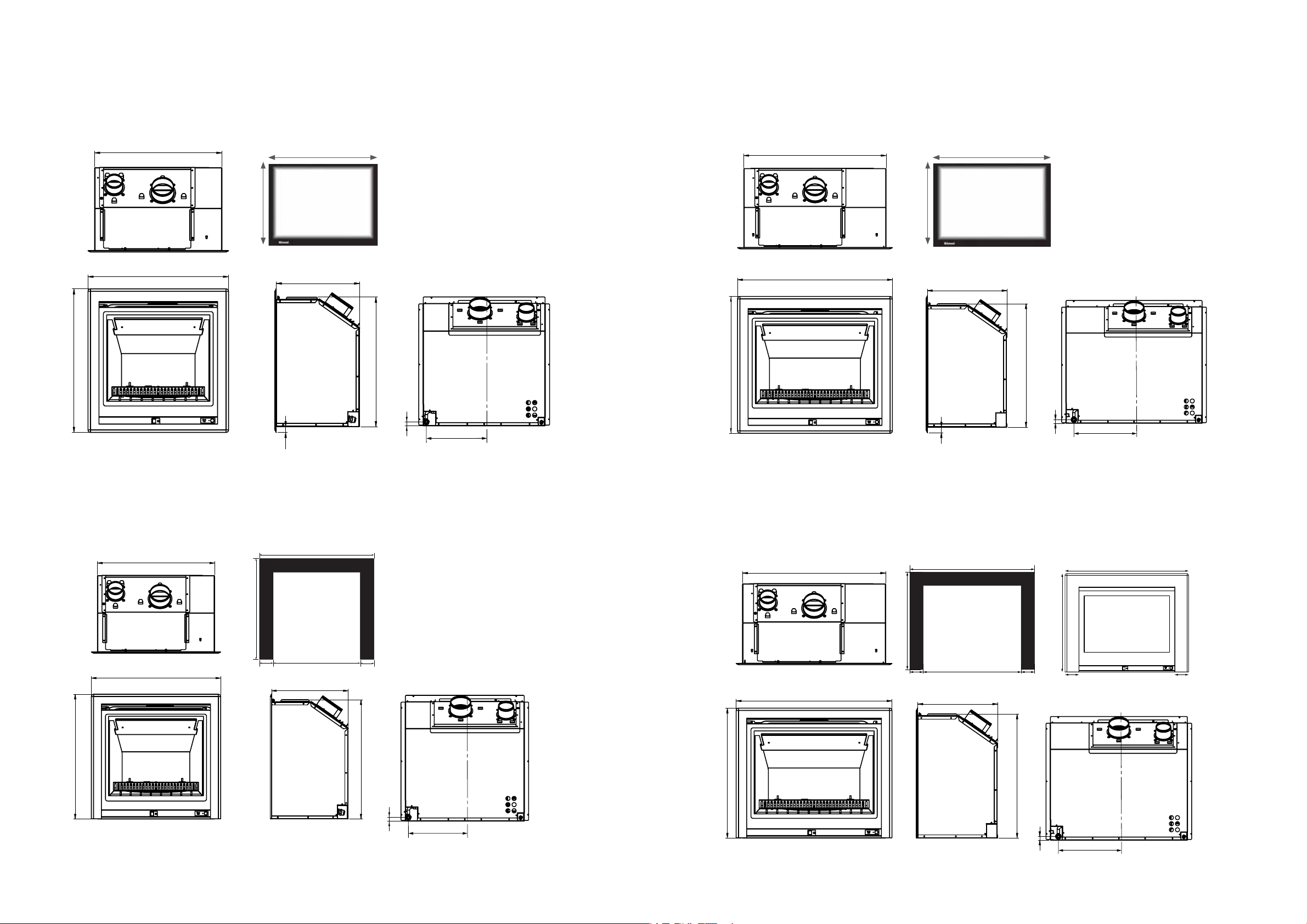
Dimensions (mm)
26
Ember 600 with 4-sided frame (mock chimney installations) Ember 700 with 4-sided frame (mock chimney installations)
644
580
640
540 mm
Viewable glass
dimensions, same
for both 600
500 mm
models
26
380
590
18
287
644
680
740
640 mm
Viewable glass
dimensions, same
for both 700
500 mm
models
380
590
18
312
Ember 600 with 3-sided frame (masonry installations or mock
chimney installations with a hearth)
790
infill panel
380
590
18
287
618
580
640
695
95 95600
Ember 700 with 3-sided frame (masonry installations or mock
chimney installations with a hearth)
618
680
740
890
infill panel
695
95 95
700
380
590
658
92.5 92.5
18
312
825
masonry
frame
6 | Ember Installation Guide: 12890-B 02-18
Ember Installation Guide: 12890-B 02-18 | 7
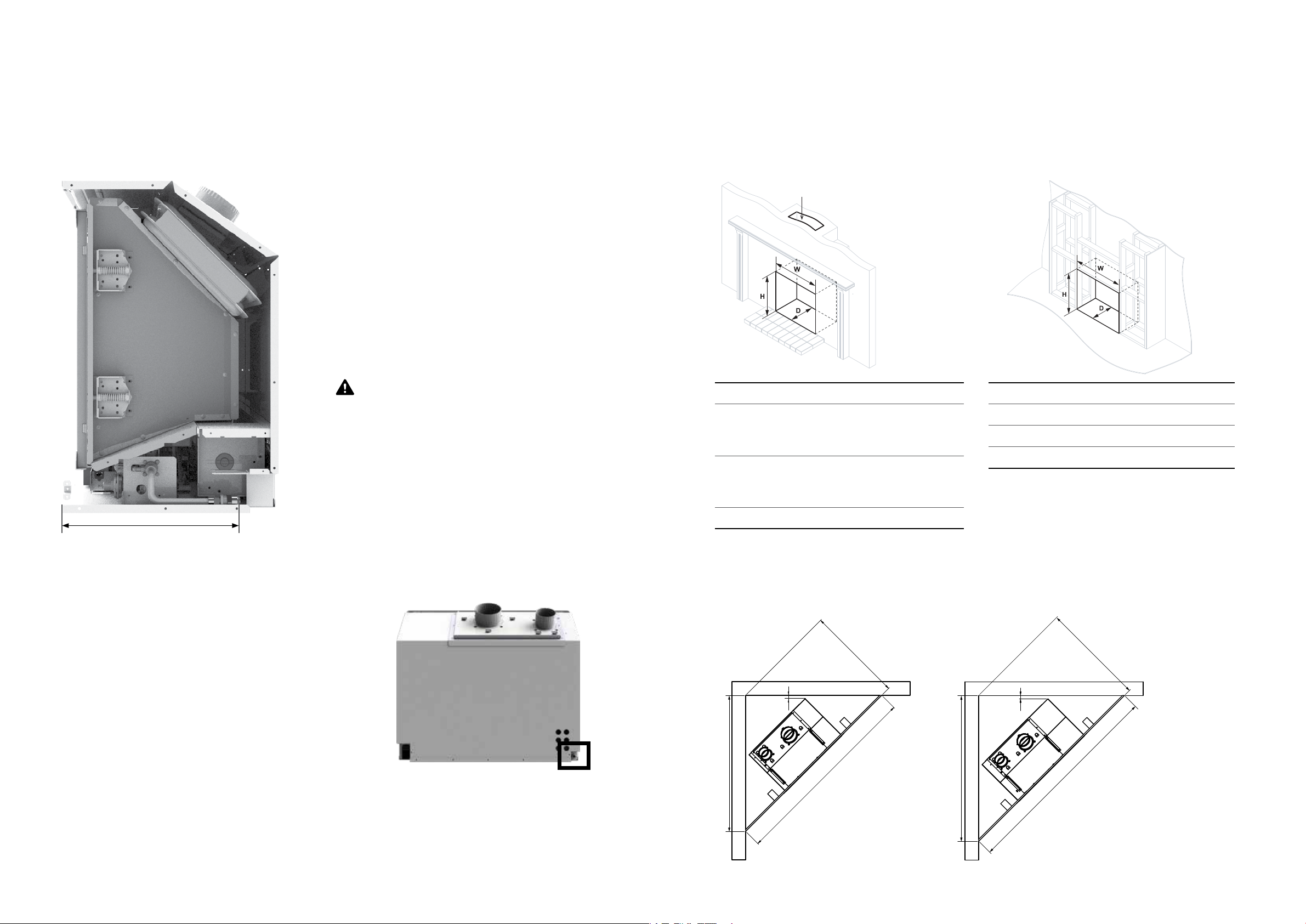
Gas supply
993
Enclosure dimensions
Gas pipe sizing must consider the gas input to this appliance, as well as other gas
appliances in the premises. The gas supply termination is inside the heater, and
enters from the lower right hand side of the appliance.
Purging the gas supply
Foreign materials and debris such as swarf,
filings etc. must be purged from the gas
supply. Failure to do so may cause damage to
the control valve causing it to malfunction.
Gas connection
A small spanner has been provided, located
in the commissioning pouch on top of the
PCB cover, to help with the gas connection as
space is quite tight. Please return the spanner
to the pouch when finished.
The use of a rubber hose for any gas
connection to a fixed appliance is not
authorised by the manufacturer.
The Ember must be positioned within the enclosure on a flat level surface that
allows free movement of the appliance. The enclosure must be capable of
supporting 1.5 times the weight of the Ember.
Masonry
Actual chimney size needs to be at least 200 x 200 mm
for the two flexi flues to fit down the chimney.
600 700
W-width
Infill panel*
Masonry frame*
H-height
Infill panel*
Masonry frame*
600 mm
600-750 mm
N/A
600 mm
600-675 mm
N/A
700 mm
700-850 mm
700-785 mm
600 mm
600-675 mm
600-638 mm
Mock chimney
600 700
W-width 700 mm 800 mm
H-height 700 mm 700 mm
D-depth 400 mm min. 400 mm min.
Framing dimensions above are before the zero clearance
frame is fitted.
approx. 320 mm
Electrical supply
The Ember is fitted with a 1.5 m power cord and 3-pin plug.
The power cord passes through a slot in the back left hand
corner of the appliance.
The connection is either direct wired* or connected to a
power point within the cavity. This must be connected to
a dedicated earthed power point. The electric isolation
switch must be accessible after the appliance has been
installed.
The fire must not be located immediately below a socket
outlet (potential fire hazard).
If the supply cord is damaged, it must be replaced by a licensed tradesperson. This must be a
genuine replacement part available from Rinnai.
* Consult a qualified electrician if direct wiring is required as it must comply with AS/NZS 5601 and AS/NZS 3000 and other
relevant local regulations
D-depth 400 mm min. 400 mm min.
* Enclosure dimensions can be larger if using an infill
panel or a masonry frame.
Corner installations
702 min.
Ember 600
25
1404
For mock chimney installations the Ember MUST BE
installed with the Ember Zero Clearance frame, which
gives the required clearances to combustibles.
752 min.
Ember 700
25
1063
1504
8 | Ember Installation Guide: 12890-B 02-18
Ember Installation Guide: 12890-B 02-18 | 9
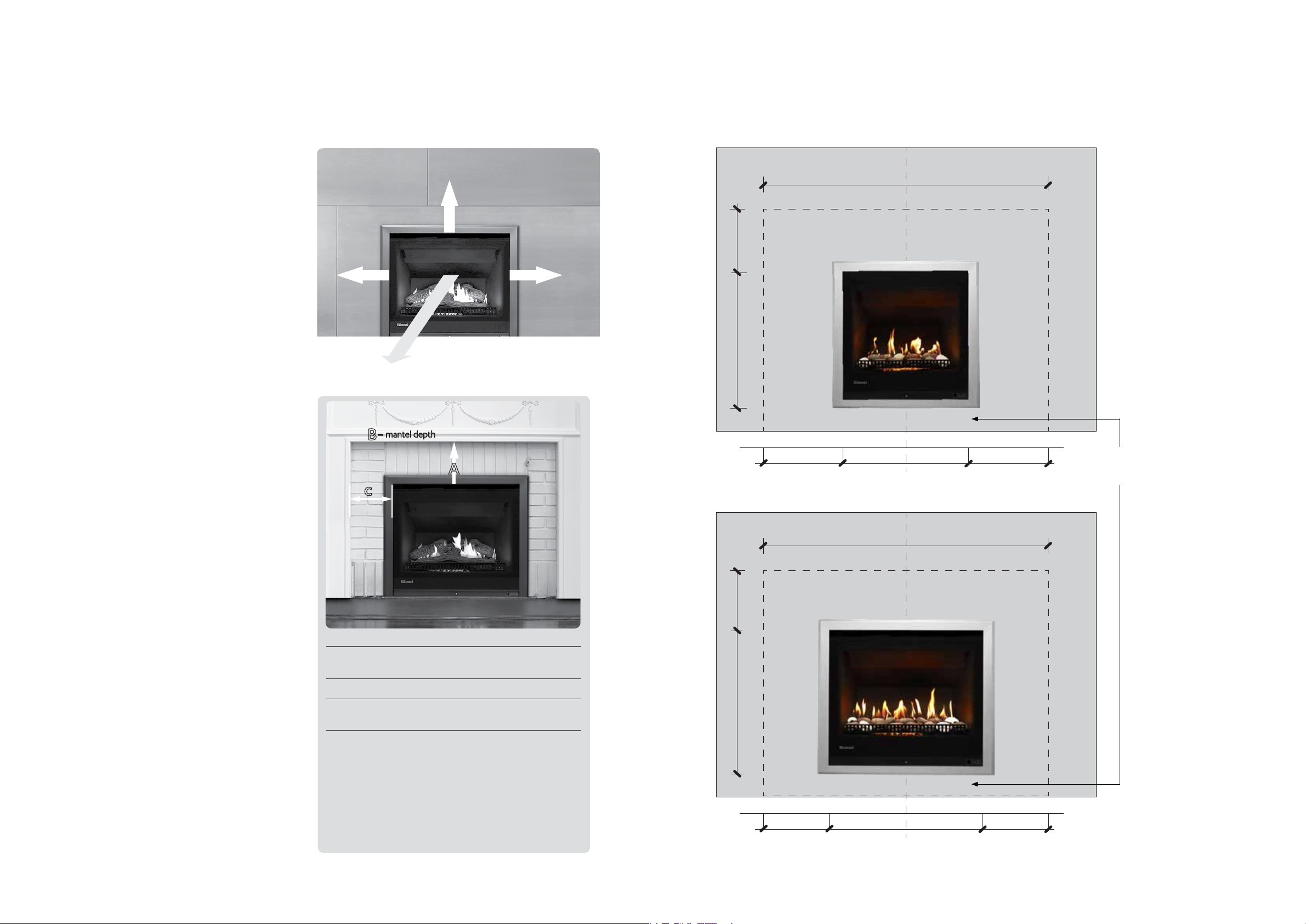
Clearances from combustibles
Glass width
Clearance Clearance
A
c
B-
mantel depth
400 mm
400 mm 400 mm
1000 mm
The clearances listed below, measured from the edge of the glass, are
minimum clearances unless otherwise stated.
The below diagrams are to assist people in determining the clearance area around the Ember
without having the unit on site. The 4-sided frame is shown as this is the frame used in mock
chimney installations, which typically have mantels and surrounds made of combustible material.
The 4-sided frame sits approximately 26 mm below the engine, refer dimension diagrams.
While the heater is operating
The appliance must not be installed where
curtains or other combustible materials
could come into contact with the heater.
The 400 mm side clearance includes side
walls. The 1000 mm clearance is in front of
the fire.
Floor protection
Heat from this fire may over time affect
the appearance of some materials used
for flooring, such as, carpet, vinyl, cork
or timber. This may be amplified if the air
contains cooking vapours or cigarette
smoke. To avoid this occurring, it is
recommended that a mat be placed in
front of the appliance.
Mantels and surrounds
Combustible mantels and surrounds
require clearance from the unit to
minimise the risk of fire. Mantels and
surrounds, made of combustible materials
such as wood, are allowed providing they
are outside the minimum clearances
shown.
Ember 600 4-sided frame
1340
Minimum above fire
570 400
Clearance Clearance
Glass width
Ember 700 4-sided frame
1440
Minimum above fire
540400 400
Distance off the floor
could be 0-400 mm.
Hearths
A hearth is not necessary but can be used
for decorative purposes or protection
of sensitive flooring if required. A hearth
must not obscure the front of the fire or
obstruct the fire in any way (including the
frame around the fire).
Wall surface above the fire
The temperature of the wall surface
directly above the fire may get warm
and distort paint finishes, or distort vinyl
wall coverings. For durability of surfaces,
please contact the manufacturer for their
specification.
10 | Ember Installation Guide: 12890-B 02-18
A Mantel needs to be a min. of 400 mm away from the
edge of the glass.
B Max. mantel depth at 400 mm (A) is 250 mm max.
C Surround needs to be a minimum of 400 mm away
from the edge of the glass.
For every 50 mm of added mantel depth there must be
an additional 100 mm of clearance from the edge of the
glass. For example:
Mantel depth A: clearance required
300 mm 500 mm
350 mm 600 mm
400 mm 700 mm
570 400
640400 400
Ember Installation Guide: 12890-B 02-18 | 11
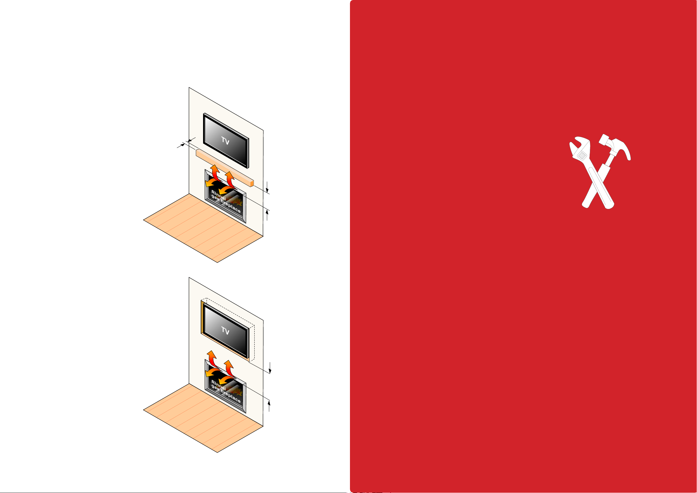
TV installation
The Ember has a fan that distributes warm air from the top of the appliance
out into the room. As warm air is dispersed outwards, as opposed to directly
upwards, installation of a TV may be an option.
The diagram shows
recommended clearances
when installing a TV directly
above the Ember, or into a
recess. All dimensions are in
millimetres.
400 mm dimension
The 400 mm dimension
is the minimum clearance
required to a mantel. The
image adjacent shows the
dimension from the edge
of the frame, in the case
of the Ember the 400 mm
dimension is to be taken from
the edge of the glass.
At least the
depth of the TV
400 mm
minimum
Installation
Installation, servicing and repair
shall be carried out only by
authorised personnel.
Always check with the TV
manufacturer
It is up to the owner to check
the TV installation with the TV
manufacturersome have
warranty conditions that state
a TV is not to be installed
above a fireplace.
Rinnai does not accept any
responsibility for damage to
a TV resulting from the use of
this information.
400 mm
minimum
12 | Ember Installation Guide: 12890-B 02-18
Ember Installation Guide: 12890-B 02-18 | 13
 Loading...