

Rinnai RDV3610ETR, RDV3611ETR, SYMMETRY RDV 3610 Operation Manual
This appliance shall be installed in accordance with:
SYMMETRY
®
All Rinnai gas products
are A.G.A. certified.
Rinnai Australia i Operation & Installation Manual
INSTALLATION REQUIREMENTS
This heater must be installed by an authorised person. The insta llation must conform to local regulations.
The installation must also comply with the instructions supplied by Rinnai.
Service and removal must be carried out by an author i sed pe rso n .
DO NOT modify this appliance.
The Rinnai Symmetry
®
has been certified by the Australian Gas Association.
The AGA Certification Number is shown on the appliance dataplate.
No parts or functions should be modified or permanently removed from the heater.
Please keep these instructions in a safe place for future reference.
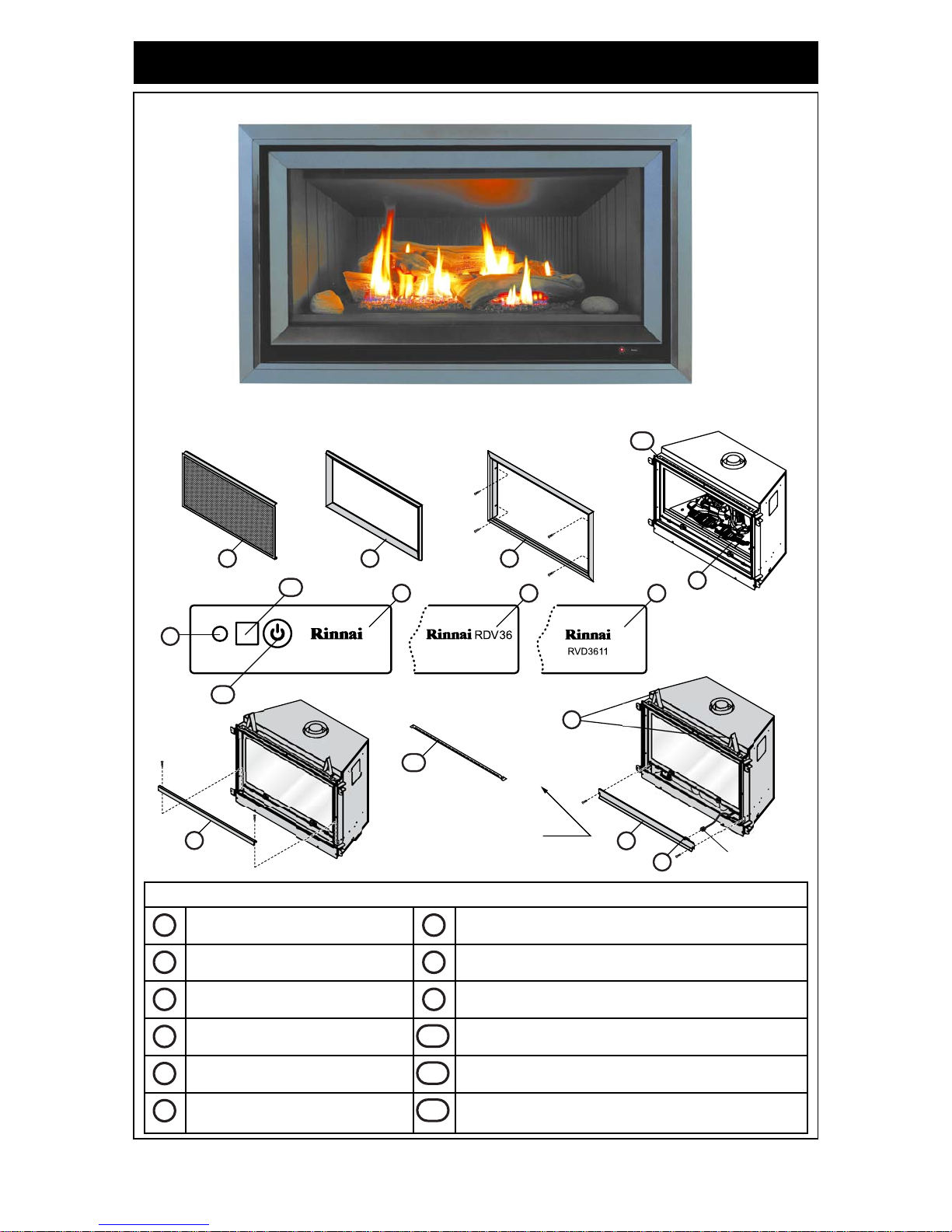
CARTON CONTENTS
For DV3610ETR check you have the following:
Carton 1
For DV3611ETR Check you have the following:
Carton 1
Carton 2
1 x Rinnai ‘Symmetry’
®
Heater.
1 x Surround (attached with 4 black screws).
1 x Operation and Installation Manual.
1 x Artificial Log Set / Burn Media (Inside appliance).
1 x Mesh Safety Guard.
2 x Lintel Spacers (attached with 4 x 8g x 8mm long self tapping pan head screws.
4 x securing brackets with 16 x 8g x 8mm long self tapping pan head screws.
1 x RF Combination Remote and Thermostatic Control with wall mount and securing screws.
2 x ‘AA’ Batteries.
1 x Flue Baffle with 2 x 8g x 8mm long self tapping pan head screws.
1 x Rinnai ‘Symmetry’
®
Heater.
1 x Operation and Installation Manual.
1 x Artificial Log Set / Burn Media (Inside appliance).
2 x Lintel Spacers (attached with 4 x 8g x 8mm long self tapping pan head screws.
4 x securing brackets with 16 x 8g x 8mm long self tapping pan head screws.
1 x RF Combination Remote and Thermostatic Control with wall mount and securing screws.
2 x ‘AA’ Batteries.
1 x Flue Baffle with 2 x 8g x 8mm long self tapping pan head screws.
1 x Pack4 x 8g x 8mm long self tapping pan head screws (for outer surround).
1 x Cladding support bracket.
1 x Outer Surround.
1 x Inner Surround.
1 x Mesh Safety Guard.
CERTIFICATION

Rinnai Australia ii Operation & Installation Manual
INSTALLATION REQUIREMENTS..............................................................................i
CARTON CONTENTS..................................................................................................i
CERTIFICATION ..........................................................................................................i
INSTALLATION RECORD ..........................................................................................1
ABOUT YOUR HEATER .............................................................................................2
FRONT LAYOUT.................................................................................................................2
SAFETY.......................................................................................................................3
SAFETY DEVICES..............................................................................................................6
ABOUT YOUR CONTROLLER...................................................................................7
CONTROLLER DISPLAY....................................................................................................7
REMOTE / THERMOSTAT CONTROL.......................................................................8
BUTTON AND DISPLAY FEATURES.................................................................................8
REMOTE CONTROLLER - INITIAL SET UP......................................................................9
WIRELESS CONTROLLER THERMOSTAT..................................................................... 10
CUSTOMER INFORMATION - OPERATION............................................................11
MODES OF OPERATION .................................................................................................11
TO TURN REMOTE ‘ON’ or ‘OFF’ ....................................................................................11
MANUAL TEMPERATURE MODE....................................................................................11
AUTOMATIC TIMER MODE .............................................................................................11
FLAME MODE...................................................................................................................11
MANUALLY OVERRIDING THE SET PROGRAM............................................................ 11
PROGRAM MODES..........................................................................................................11
FLAME HEIGHT AND FAN SPEED..................................................................................11
HOW TO OPERATE YOUR HEATER.......................................................................12
FLASHING SMALL FLAME SYMBOL ‘ON’.......................................................................12
TO BEGIN PROGRAMMING ............................................................................................12
MANUAL SWITCH MODE.................................................................................................14
LOSS OF REMOTE CONTROL FUNCTION.....................................................................14
TO REGAIN REMOTE CONTROL....................................................................................14
GAS SUPPLY DISRUPTION.............................................................................................14
POWER DISRUPTION......................................................................................................14
CARE AND MAINTENANCE.....................................................................................15
GENERAL OPERATION CHARACTERISTICS ...............................................................15
SERVICE...........................................................................................................................15
TROUBLE SHOOTING..............................................................................................16
TROUBLE SHOOTING CHECKLIST ................................................................................16
ABNORMAL FLAME PATTERN........................................................................................16
TABLE OF CONTENTS - INSTALLATION...............................................................17
CONTACT INFORMATION .......................................................................................37
TABLE OF CONTENTS - OPERATION

Rinnai Australia 1 Operation & Installation Manual
INSTALLATION RECORD
INSTALLERS / GAS FITTERS DETAILS
Installers Name: _____________________________________________________
Company Name: _____________________________________________________
Company Address: _____________________________________________________
_____________________________________________________
_____________________________________________________
Company Contact Details
Telephone: _____________________________________________________
Mobile Phone: _____________________________________________________
Certificate of Compliance / Certification Number: ______________________________
Authorised Persons - Licence Number: _______________________________________
Installers Signature: _____________________________________________________
Installation Date: _____________________________________________________
APPLIANCE DETAILS
Model Number: _____________________________________________________
Serial Number: _____________________________________________________
Installation Address: _____________________________________________________
_____________________________________________________
_____________________________________________________
_____________________________________________________
Rinnai Australia 2 Operation & Installation Manual
ABOUT YOUR HEATER
RDV3610ETR / RDV3611ETR
FRONT LAYOUT
Unit Features
Mesh Dress Guard Manual Control Switch Panel
Mesh Dress Guard Frame Lintel Stand-Off Brackets
Surround Red LED Power Indicator
Manual Control Panel Remote Sensor Receiver
Glass Panel Assembly ‘ON’ / ‘OFF’ Button
Lower Horizontal Cover Panel
Cladding Support Bracket
(Fitted to RDV3611ETR models Only!)
Note: Cladding support
bracket fitted to
RDV3611ETR models Only!
6
7
RJ45
Connector
4
8
Typical
2
places
1 2 3
5
9
11
10
4 4 4
12
12
RDV3611ETR RDV3610ETR
1
7
2
8
3
9
4
10511
6
12
Rinnai Australia 3 Operation & Installation Manual
SAFETY
• Failure to comply with these instructions could result in a fire or explosion, which
could cause serious injury, death or property damage.
• Improper installation, adjustments, service or maintenance can cause serious
injury, death or property damage. Such work must be performed by an authorised
person.
• The appliance must be installed in accordance with the local gas and electrical
authority regulations.
• Flue terminal must always vent directly to outdoors.
• DO NOT extend the flue vertically or horizontally in ways other than prescribed in
the appliance manufacturers’s installation instructions.
• For information on gas consumption, see data plate on the appliance.
• This appliance must not be installed where curta ins or other combus tible materials
could come into contact with it. In some cases curtains may need restraining.
• WARNING: This heater must not be used if the glass panel is damaged.
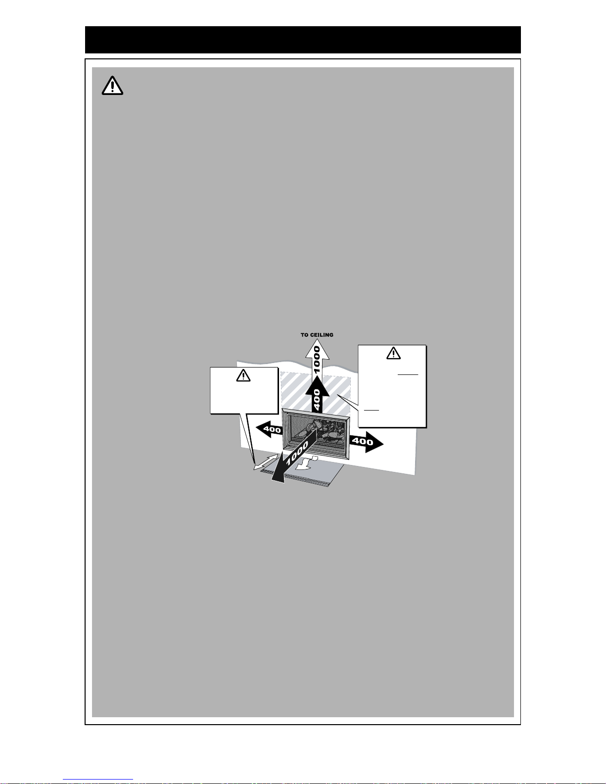
• Minimum clearances during operation as follows:
• Heat emanating from the front of t his heater may over time a ffect the appea rance of
some materials used for flooring such as carpet, vinyl, cork or timber. This effect
may be amplified if the air in the room contains cooking vapours or cigarette
smoke. To avoid this possibility, it is recommended that a mat be placed in front of
the appliance, extending at least 750 mm in front of the air outlet.
• This appliance is not intended for use by persons (including children) with reduced
physical, sensory or mental capabilities or lack of experience and knowledge,
unless they have been given supervision or instruction concerning use of the
appliance by a person responsible for their safety.
• Young Children must be supervised when in the vicinity of this heater while it is in
operation.
• The Mesh Dress Guard MUST be fitted to this appliance to reduce the risk injury
from burns and no part of it should be permanently removed.
• For protection of young children or the infirm a secondary guard is required.
WARNING
On heat sensitive
surfaces provide
protective matting
to at least 750mm
Non-combustible
cladding MUST
be provided for
RDV3610ETR
installations.
NOT required on
RDV3611ETR
installations.

Rinnai Australia 4 Operation & Installation Manual
SAFETY
Unpack the heater and check for damage. DO NOT INSTALL DAMAGED HEATER. If the heater is
damaged, contact your supplier for advic e. Before ins talling the he ater , chec k the lab el for the corr ect
gas type (refer rating plate, inside the appliance).
Remove shipping clamps on bottom edge of appliance before attempting to lift heater.
Refer to local gas authority for confirmation of the gas type if you are in doubt.
• If the supply cord is damaged or requires replacing, it must be replaced by the
manufacturer or the manufacturer's agent or similarly qualified person in order to
avoid a hazard.
• Heater must not be located immediately below a power socket outlet.
• DO NOT connect to an LPG Gas cylinder indoors.
• A dedicated 240 V earthed 10 Amp power point must be used with this appliance.
• The appliance is not intended for use by young children or infirm persons without
supervision.
• DO NOT modify this appliance. Modifying from original specifications may cre ate a
dangerous situation and will void your warranty.
• Only the flue components specified by Rinnai must be used.
WARNING
Rinnai Australia 5 Operation & Installation Manual
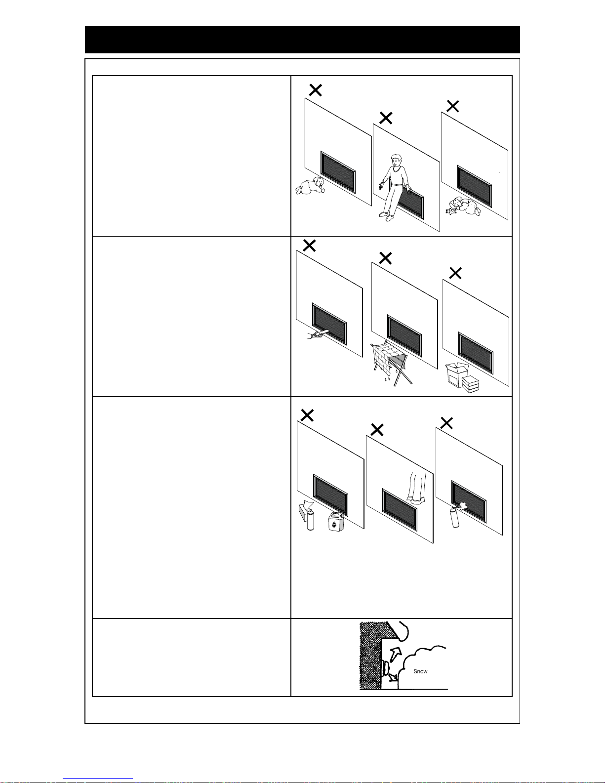
SAFETY
The appliance is not intended for use by
young children or infirm persons without
supervision.
Young children should always be supervised
to ensure that they DO NOT play with the
appliance.
DO NOT allow children or elderly persons to
sleep in the warm air discharge from the
heater.
DO NOT sit or lean against the heater.
DO NOT post or allow children to post articles
into the louvres of the heater.
DO NOT cover or place articles on this
heater.
DO NOT place articles in front of the louvres.
DO NOT operate / install this heater in areas
where painting is taking place, or in places
such as hairdressing salons, where there
may be fluff and dust, and where aerosols are
used.
DO NOT place articles on or against this
appliance.
DO NOT use or store flammable materials
near this appliance.
Keep flammable materials away from heater.
Combustible materials must not be placed
where the heater could ignite them.
DO NOT spray aerosols in the vicinity of this
appliance while it is in operation.
Most aerosols contain butane gas which can
be a heater hazard if used near this heater
when it is in use.
Snow Areas - in areas subject to heavy
snowfall, keep snow clear of flue terminal at
all times.
Keep flammable materials, trees shrubs etc.
away from the flue terminal.

Rinnai Australia 6 Operation & Installation Manual
SAFETY
A dedicated 240V earthed 10 Amp power
point must be used with this appliance.
DO NOT use power boards or double
adaptors to operate this appliance. Heater
MUST NOT be located below a power
socket-outlet.
DO NOT place containers of liquid on top of
the heater. Water spillage can cause
extensive damage to the appliance and
create an electrocution hazard.
DO NOT place articles on or against this
appliance.
Turn the heater ‘OFF’ after use.
DO NOT unplug the heater while it is in
operation or while the fan is still cycling.
Heat emanating from the front of the
appliance may over time affect the
appearance of some materials used for
flooring such as carpet, vinyl, cork or timber.
This effect may be amplified if the air in the
room contains cooking vapours or cigarette
smoke. To avoid this possibility, it is
recommended that a mat be placed in front of
the appliance, extending at least 750 mm in
front of the heater.
When the heater is operated for the first time
or after long periods of non use a slight odour
may be emitted, this is normal. However if
odours persist switch ‘OFF’ the appliance and
contact Rinnai.
SAFETY DEVICES
• Over Heat Switches
When the heater gets too hot during opera tion (for example when air outlet lou vres are blocked)
these devices turn the gas off automatically and allow the heater to restart when cooled down.
• Electrical Fuse
The electrical circuits are protected by a fuse.
• Flame Failure Sensing System
This device automatically cuts off the gas supply to the heater in the event of a flame failure.
• Power Failure
In the event of a power failure or power cut, the gas valves will automatically close. The remote
control/thermostat will restart the appliance at the next programmed time period.
AT LE AS T
750 mm
Rinnai Australia 7 Operation & Installation Manual
ABOUT YOUR CONTROLLER
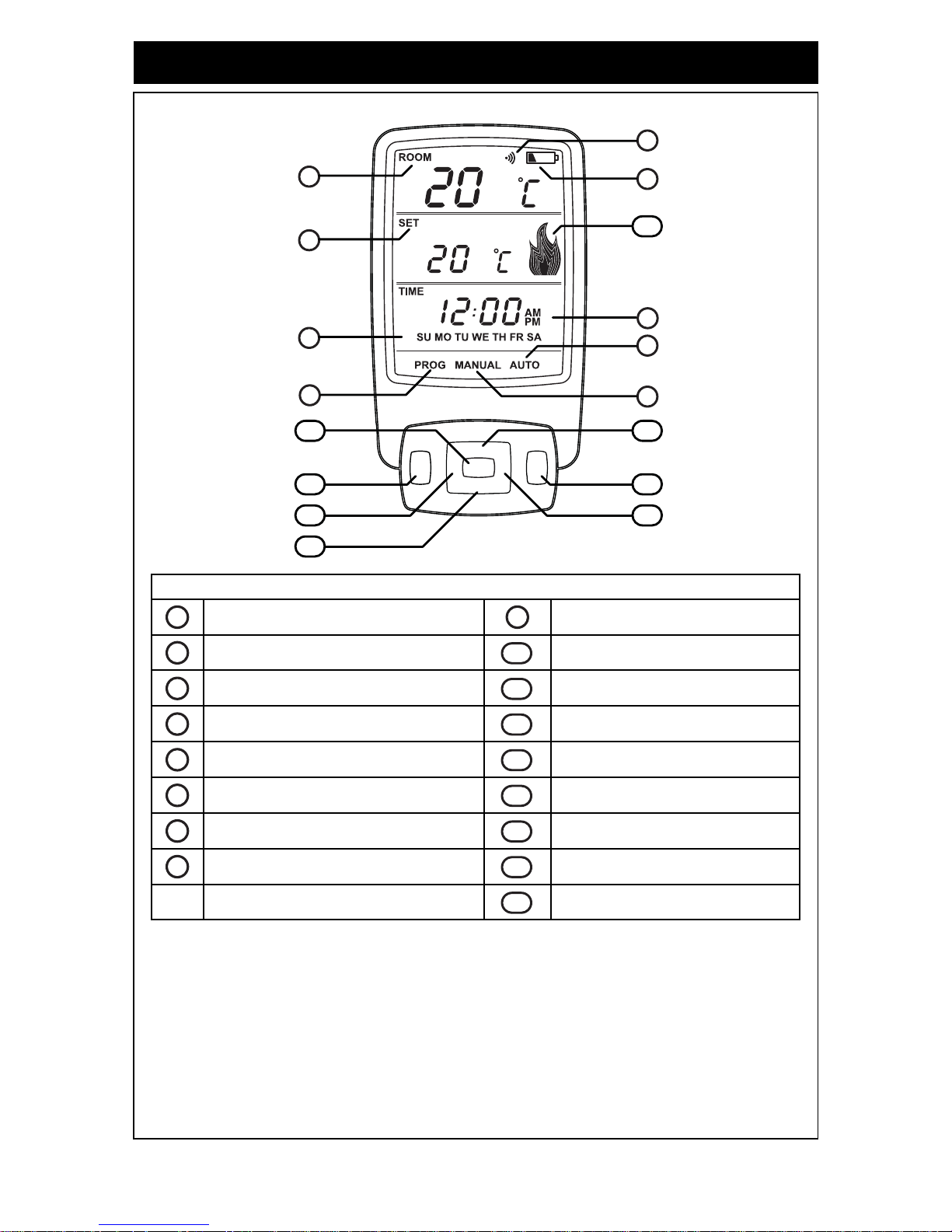
CONTROLLER DISPLAY
LCD DISPLAY
Time of day with ‘AM’ or ‘PM’ display Manual mode indicator
Day of the week Setting ‘UP’ Button
Current Room temperature display ‘OK’
Button
Setting Temperature with ‘SET’ display ‘PWR’ (Power) Button
Transmit indicator ‘A/M’ Button
Battery Low indicator ‘T’ (Time) Button
Automatic mode indicator Setting ‘DOWN’ Button
Program mode indicator ‘P’ (Program) Button
Flame Indicator
A/M PWRTP
DOWN
UP
OK
A/M PWR
OK
TP
DOWN
UP
1
2
6
9
8
5
7
17
10
11
14
15
16
13 12
4
3
1
9
2
10
3
11
4
12
5
13
6
14
7
15
8
16
17

Rinnai Australia 8 Operation & Installation Manual
REMOTE / THERMOSTAT CONTROL
BUTTON AND DISPLAY FEATURES
Item Feature / Function Symbol Description
1
Time of day Displays time of the day in hours and minutes,
‘AM’ or ‘PM’. The time is displayed when the
thermostat is ‘ON’ or ‘OFF’
2
Day of week
‘SU - SA’
Displays the current day of the week. The day
is displayed when the thermostat is ‘ON’ or
‘OFF’.
3
Current room temperature
display
Displays the current temperature.
The temperature range is 7°C - 32°C.
4
Setting temperature display
‘SET’
When the thermostat is ‘ON’, the programmed
(set) temperature will be displayed.
5
Transmit indicator Indicates that the thermostat is transmitting to
the receiver, the symbol will appear on the
LCD for 1 sec.
6
Battery low indicator Indicates when the battery power is below an
acceptable level.
7
9
Automatic mode indication
Manual mode indication
‘MANUAL’
‘AUTO’
Indicates if the thermostat is in manual or
automatic mode.
8
Programming mode
indication
‘PROG’
Indicates that the thermostat is in programming
mode.
10
Up
‘UP’
Increase hours, minutes, day or temperature
11
OK Enter
‘OK’ ‘ENTER’
Accepts the current function and advances to
the next function.
12
Power ‘ON’ / ‘OFF’ (+ OK) ‘PWR’ + ‘OK’
Switches the thermostat ‘ON’ and ‘OFF’. To
turn ‘ON’ press and release the ‘PWR’ and
‘OK’ Buttons at the same time this will turn the
thermostat ‘ON’ to the most recently
programmed working mode.
13
Automatic / Manual /
Flame Mode
‘A / M’
T oggles between automatic, manual and flame
mode.
14
Time ‘T’
Initiates time and day of the week
programming (must press and hold for 2 or
more seconds when the thermostat is ‘OFF’).
15
Down ‘DOWN’
Decrease hours, minutes, day or temperature
16
Program ‘P’
Initiates the programming mode (must press
and hold for 2 or more seconds when the
thermostat is ‘OFF’).
17
Flame Indicator
Indicates the flame setting.
The Flame symbol graphically indicates which
of the 7 graduated settings between Low and
High flame when the burner is on.
In AUTO or MANUAL temperature mode, if the
burner is OFF due to room temperature being
reached the symbol will modulate UP and
DOWN. This is to indicate that the unit is still
ON even though there are no flames visible in
the appliance.

Rinnai Australia 9 Operation & Installation Manual
REMOTE / THERMOSTAT CONTROL
REMOTE CONTROLLER - INITIAL SET UP
Before you start
Carefully remove the battery compartment cover panel from the rear of your controller hand-set
and correctly insert the two AA batteries supplied ensuring '+' and '-' polarity is correct.
When installing your batteries your remote control will display the 'Initial
Set-up Screen'. The screen will display the following:
• Current room temperature in Deg.C
• Default time setting of
• Default day of the week setting ‘MO’ - Monday.
When changing batteries all settings will be lost and the controller will revert back
to the 'Initial set -up screen'.
Setting the Current Time and Day of the Week
Step 1). Install batteries by removing the cover at the rear of the remote
controller unit.
Step 2).Press and hold the ‘T’ button for approximately 2 seconds.
‘TIME’
, ‘HOUR’ and ‘A/M’ will flash.
If no buttons are pressed the display will revert back to 'Initial Set-Up Screen'
retaining the last entered setting.
Step 3).To select the hour push the
‘UP’ or ‘DOWN’ button until the
desired hour is chosen, note that AM or PM is chosen by cycling
through the 12 hour range.
Step 4). Press ‘OK’ to enter the selected hour and
AM or PM. ‘TIME’ + minutes + ‘A/M’ will
flash.
Step 5). To select the minutes push the ‘UP’
or ‘DOWN’ button until the
desired minutes are chosen. (See Step 3 for ‘UP’
and ‘DOWN’
Buttons).
Step 6). Press ‘OK’ to enter selected minutes, the ‘MO’ Monday will
flash. (See Step 4 for ‘OK’ Button).
Step 7). To select correct day push the ‘UP’
or ‘DOWN’ Button until the
desired day is chosen. (See Step 3 for ‘UP’
or ‘DOWN’
Buttons).
Step 8). Press ‘OK’ to enter the selected day, time & day are now correctly set.
(See Step 4 for ‘OK’ Button).
To adjust time for Daylight Saving time
To adjust time or to adjust for daylight savings follow Steps 2 - 6 press ‘OK’
button twice after
selecting minutes to keep current day.
When changing batteries all settings will be lost and the controller will revert back
to the 'Initial set -up screen'. Re-setting of time, date and programming will be
necessary.
NOTE
MO
NOTE
A/M PWRTP
DOWN
UP
OK
A/M PWRTP
DOWN
UP
OK
MO
NOTE
 Loading...