

Rinnai RCE-592ACPA Owner's Operation Manual And Installation Manual

THIS IS AN UNVENTED GAS-FIRED HEATER. IT USES AIR (OXYGEN)
FROM THE ROOM IN WHICH IT IS INSTALLED. PROVISIONS FOR
ADEQUATE COMBUSTION AND VENTILATION AIR MUST BE PROVIDED.
REFER TO INSTALLATION INSTRUCTIONS ON PAGE 6.
INSTALLER:Leave this manual with the appliance.
CONSUMER:Retain this manual for future reference.
This appliance may be installed in an aftermarket, permanently located,
manufactured (mobile) home, where not prohibited by local codes.
This appliance is only for use with the type of gas indicated on the rating plate.
This appliance is not convertible for use with other gases.
WARNING: IF THE INFORMATION IN THIS MANUAL IS NOT FOLLOWED
EXACTLY, A FIRE OR EXPLOSION MAY RESULT CAUSING PROPERTY
DAMAGE, PERSONAL INJURY OR LOSS OF LIFE.
DO NOT STORE OR USE GASOLINE OR OTHER FLAMMABLE VAPORS
AND LIQUIDS IN THE VICINITY OF THIS OR ANY OTHER APPLIANCE.
WHAT TO DO IF YOU SMELL GAS
�
DO NOT TRY TO LIGHT ANY APPLIANCE.
�
DO NOT TOUCH ANY ELECTRICAL SWITCH; DO NOT USE ANY PHONE
IN YOUR BUILDING.
�
IMMEDIATELY CALL YOUR GAS SUPPLIER FROM A NEIGHBOR'S
PHONE. FOLLOW THE GAS SUPPLIER'S INSTRUCTIONS.
�
IF YOU CANNOT REACH YOUR GAS SUPPLIER, CALL THE FIRE
DEPARTMENT.
INSTALLATION AND SERVICE MUST BE PERFORMED BY A QUALIFIED
INSTALLER, SERVICE AGENCY OR THE GAS SUPPLIER.
HOME OWNER / INSTALLER
FOR YOUR SAFETY
THIS MANUAL MUST BE READ IN ITS
ENTIRETY BEFORE OPERATING HEATER
RCE-592ACPA
VENT-FREE GAS CONVECTION HEATER
With Plasmacluster
TM
+HEPA AIR CLEANING TECHNOLOGY
FC-420 HEP
A
+
Owner's Operation and lnstallation Manual
CORPORATION
NAGOYA, JAPAN
WARNING
THIS APPLIANCE IS INTENDED FOR SUPPLEMENTAL HEATING.
IMPROPER INSTALLATION, ADJUSTMENT, ALTERATION, SERVlCE OR
MAINTENANCE CAN CAUSE PROPERTY DAMAGE, PERSONAL
INJURY OR LOSS OF LIFE. REFER TO THE OWNER'S INFORMATION
MANUAL PROVIDED WITH THIS APPLIANCE. INSTALLATION AND
SERVICE MUST BE PERFORMED BY A QUALIFIED INSTALLER,
SERVICE AGENCY OR THE GAS SUPPLIER. FOR ASSISTANCE OR
ADDITIONAL INFORMATION CONSULT A QUALIFIED INSTALLER,
SERVICE AGENCY OR THE GAS SUPPLIER.
TABLE OF CONTENTS
GENERAL INFORMATION
THIS
SERIES HEATER IS DESIGN CERTIFIED BY CSA INTERNATIONAL AS
A VENT-FREE ROOM HEATER AND MUST BE INSTALLED ACCORDING TO
THESE INSTRUCTIONS.
ANY ALTERATION OF THE ORIGINAL DESIGN INSTALLED OTHER THAN AS
SHOWN IN THESE INSTRUCTIONS OR USED WITH A TYPE OF GAS NOT
SHOWN ON THE RATING PLATE, IS THE RESPONSIBILITY OF THE PERSON AND
COMPANY MAKING THE CHANGE.
SPECIFICATIONS
SAFETY DEVICES
IMPORTANT POINTS
SAFETY POINTS
USAGE AND INSTALLATION INFORMATION
INSTALLATION INSTRUCTIONS
OPERATING INSTRUCTION PLATE
CONTROL PANEL OPERATING INFORMATION
REPLACING THE HEPA FILTER
OPERATING THE HEATER
TIMER OPERATION
MAINTENANCE / SERVICE
TROUBLE SHOOTING CHART
SCHEMATIC DISASSEMBLY
ERROR MESSAGES
LIMITED WARRANTY
................................................................................................................1
................................................................................................................1
...........................................................................................................2
..................................................................................................................3
......................................................................5
..........................................................................................6
....................................................................................9
...............................................................10
.........................................................................................11
................................................................................................12
...........................................................................................................14
...............................................................................................17
..........................................................................................20
..............................................................................................22
..........................................................................................................28
...........................................................................................back cover
Page
WARNING
THIS APPLIANCE IS EQUIPPED FOR (NATURAL OR PROPANE) GAS.
FIELD CONVERSION IS NOT PERMITTED.
- 1 -
SPECIFICATIONS
Overheat Switch
When the heater gets too hot during operation (for example when the filters or air outlet louvers are
blocked) this device turns the gas off automatically. Remove cause of overheat (clean filters) allow
heater to cooI, then re-ignite.
Fuse
The electrical circuits are protected by a fuse. When the fuse blows, the heaters will not operate at all.
The fuse must be replaced by an authorized person.
Flame Failure Device
This device automatically cuts off the gas supply to the heater in the event of a gas failure. To restore
the gas supply to the heater, turn it off, then follow the ignition procedure.
Oxygen Depletion Safety Device
If the oxygen level in the room drops below a pre-set limit, this device cuts the gas supply off to the
heater. If the oxygen depletion device operates, turn the heater off, ventilate the room, then follow the
ignition procedure to re-light. Heater will not re-Iight until room is fully ventilated.
Tilt Switch
If the heater is knocked over, the tilt switch will cut the gas supply off. The fan keeps running. To
restore the gas supply, stand the heater upright, turn it off then follow the ignition procedure. The tilt
switch may also operate if the heater is jolted or picked up while in operation.
Power Failure
In the event of a power failure or power cut, the gas valves will automatically close. After the power is
re-instated the appliance must be restarted manually.
"-N" Models are for Natural Gas. (Inlet Pressure within 5.9"-10.5" W.C.)
"-N" Models manifold pressure: 5.1" W.C.
"-P" Models are for L.P. Gas. (Inlet Pressure within 7.9"-13" W.C.)
"-P" Models manifold pressure: 6.2" W.C.
Gas connection pipe size 1/2" N.P.T.all models.
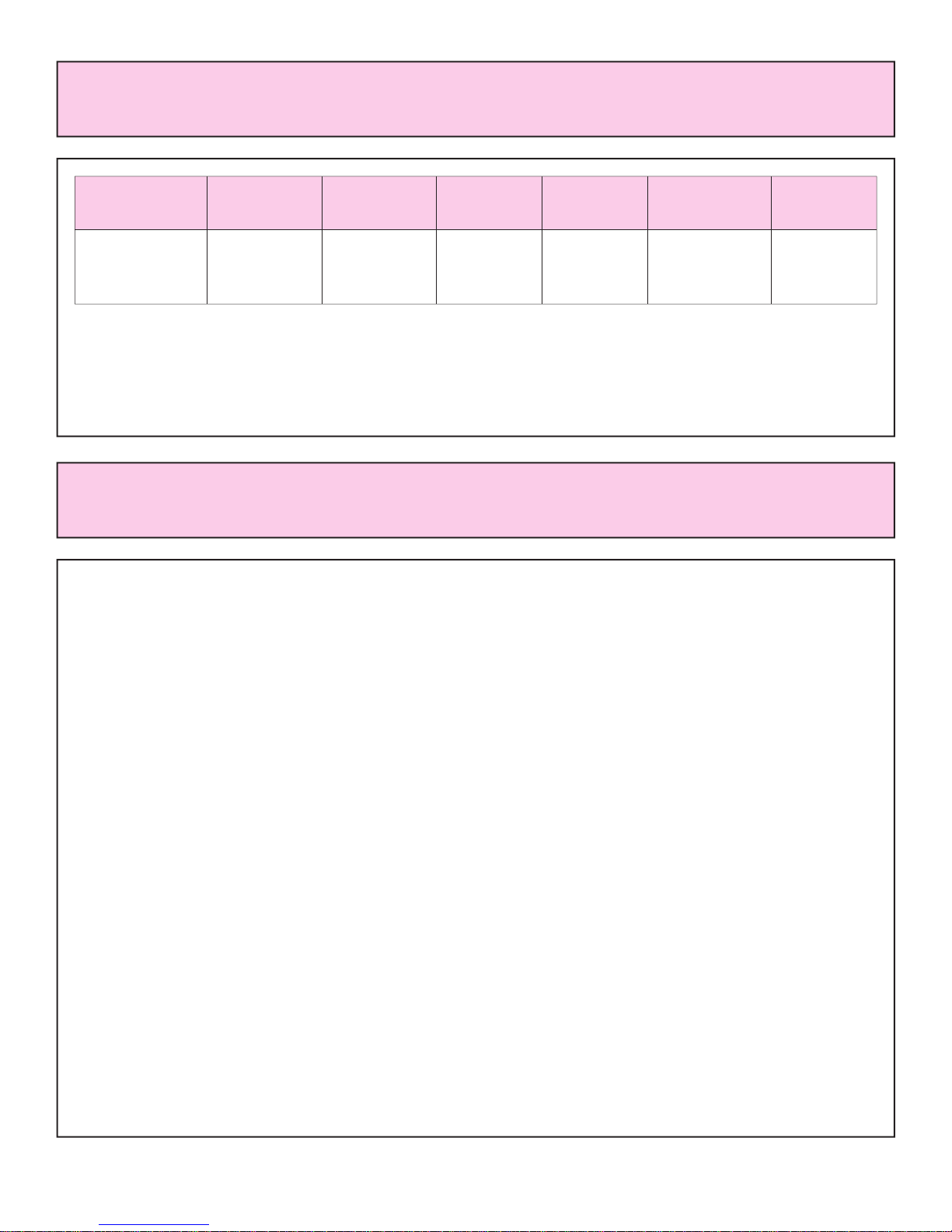
SAFETY DEVICES
Model
RCE-592ACPA-N
RCE-592ACPA-P
Input Rating
BTU/H HIGH
20,000
18,000
Input Rating
BTU/H LOW
4,000
6,000
Thermostat
YES
YES
Weight
in pounds
32
Dimension
in inches
Height: 26 3/10"
Width: 18 9/10"
Depth: 11 4/10"
Fan CFM
Output
High:129
Low:82
UNPACK HEATER:
Check for damage. (DO NOT INSTALL DAMAGED HEATER.) If heater is damaged, contact your
supplier for advice. Before installing a heater, check the label for the correct gas type (see label on back
of heater). Refer to local gas authority for confirmation of gas type if you are in doubt.
INCLUDED IN CARTON:
Customers Operating Information/Manual Gas Valve
IMPORTANT
1. The appliance must be installed in accordance with state and local codes.
2. For information on gas rate, see data plate on the appliance.
3. When using this appliance, ensure that the room is correctly ventilated. Check the local gas
authority for information on ventilation requirements.
4. The heater must not be installed where curtains or other combustible materials could come into
contact with it. In some cases, curtains may need restraining. It must be installed 2" (50mm) away from
walls.
5. This appliance is not designed to be built in.
6. If you move, check the gas type in the area where you are moving to. The local gas authority will be
able to advise on local regulations.
7. This heater discharges a large volume of warm air at low level to provide even heat distribution. If
the air in the room contains cooking vapor or cigarette smoke, and the heater is used on a carpet,
the surface of the carpet may become discolored.
In addition, some nylon carpets contain dyes which may be affected by the warm air flow. Some soft
vinyl surfaces are also subject to distortion, or discoloration by warm air. To prevent discoloration of
carpets etc., a nonflammable board should be placed under the appliance, extending about 30" (750mm)
in front of it.
- 2 -
IMPORTANT POINTS
- 3 -
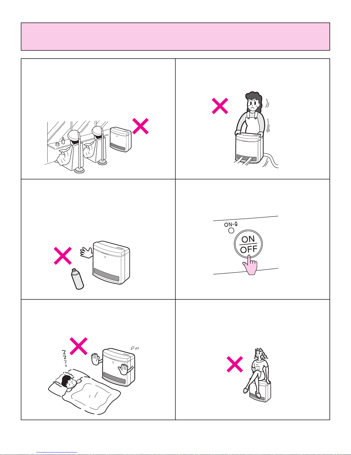
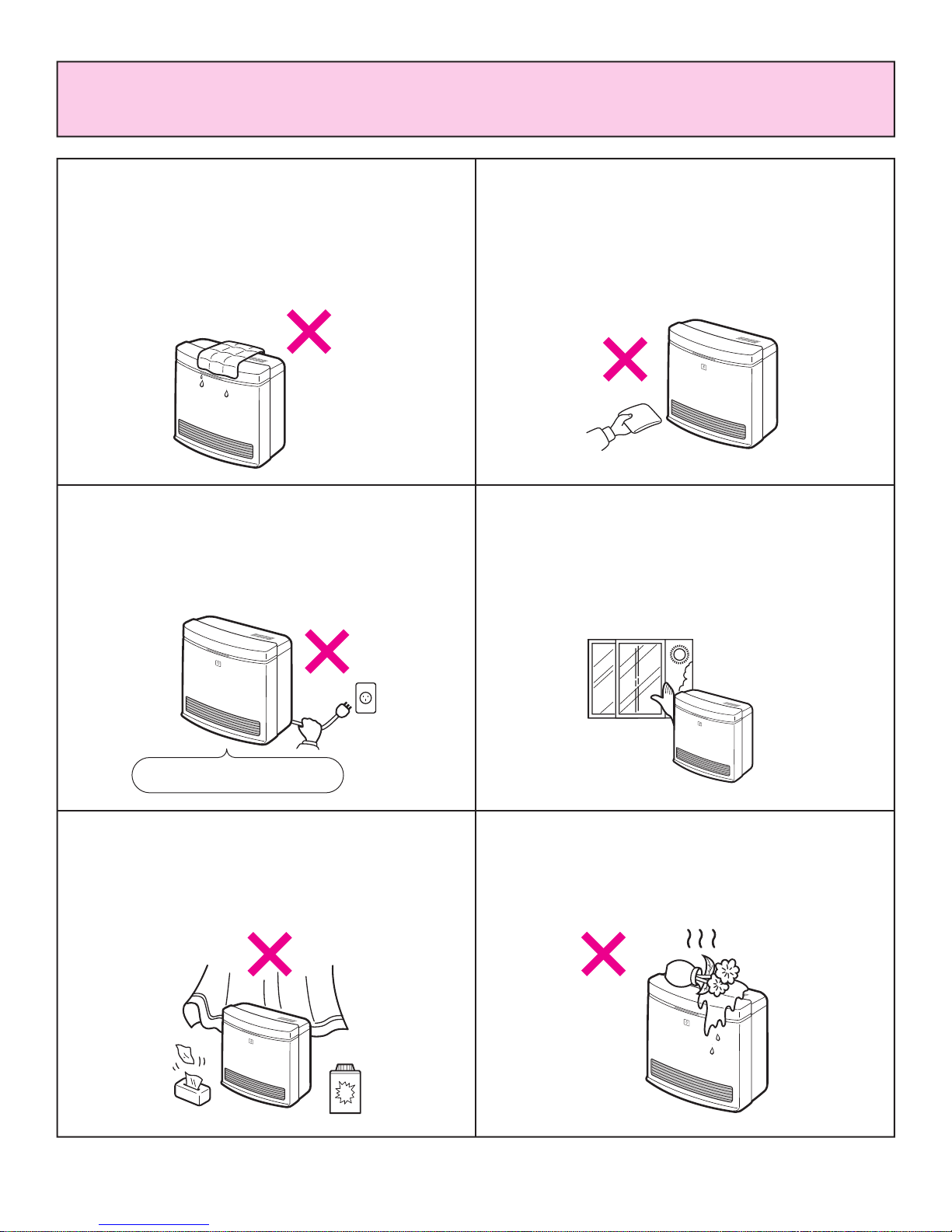
SAFETY POINTS
Do not install this heater in areas where
spray painting or plating is taking place, or
in places such as hair dressers, where
there may be a lot of fluff and dust, and
where aerosols are used. May create
strong odors and irritate eyes and sinuses.
Do not move the heater while it is turned on.
Do not spray aerosols near this heater while
it is in use. Many aerosols contain flammable
gas and can be a fire hazard. Use of
aerosols, paint, polishes etc., while this
heater is in use will cause unpleasant smells.
Turn off heater when not in use and when
away for long periods of time.
Do not allow children or elderly persons to
sleep in the warm air discharge from the
heater.
Do not sit on this heater.
ON / OFF BUTTON
- 4 -
SAFETY POINTS
Do not unplug during operation
Do not allow children to put articles in the
louvers.
Supervise children playing near this heater.
Do not place wet articles on this heater, the
water may drip into the electrical parts.
Do not turn the heater off by unplugging it
from the wall, or while the fan is cooling the
heater off. (This heater is not suitable for use
with a plug in type timer.)
Ventilate the room when this heater is in
use. Correct, fixed ventilation is usually
sufficient, consult your local gas authority
for local regulations.
Keep away from flammable materials.
Combustible materials must not be placed
where the heater could ignite them.
Do not place articles in front of the hot air
discharge.
Do not place containers of liquid on top of
the heater. Water in the heater can cause
extensive damage.
1. Read these rules and the instructions carefully. Check all local codes. Failure to follow these could
cause a malfunction of the heater resulting in death, serious bodily injury and/or property damage.
2. This heater is designed for use only with one type of gas, either L.P.G. or Natural Gas. Make sure
that the type of gas to be supplied to this unit matches that shown on the rating plate on the heater.
This unit is not convertible to another fuel.
3. WARNING: Any change to this heater or its controls can be dangerous.
4. If a gas leak is suspected, turn heater off, turn gas supply valve off at regulator or appliance
connecter valve. Open windows to ventilate area immediately and contact your dealer or gas
company.
5. WARNING: Failure to keep the primary air opening(s) of the burner(s) clean may result in sooting
and property damage.
6. Installation and repair should be done by a qualified service person. Heater should be inspected
before use and at least annually by a professional service person. More frequent cleaning may be
required due to excessive lint from carpeting, bedding material, etc. It is imperative that control
compartment, burners and circulating air passageways be kept clean.
7. An unvented room heater having an input rating of more than 10,000 BTU's per hour shall not
be installed in a bedroom or bathroom or where state or local codes do not allow.
An unvented room heater having an input rating of more than 6,000 BTU's per hour shall not
be installed in a bathroom or where state or local codes do not allow.
8. Keep area near the heater clear and free from combustible materials, gasoline and other flammable
vapors and liquids.
9. Due to its high temperature, the heater should be located out of traffic and away from furniture and
draperies.
10. Do not place clothing or flammable material on or near the heater.
11. Any safety panel or guard removed for servicing must be replaced prior to operating the heater.
12. An unvented gas heater will increase the amount of humidity in the room.
13. This heater is intended for space heating purposes only. Do not use for other purposes such as
drying clothes or baking paints.
14. Do not touch the outlet area while the heater is in use. To avoid burns, do not move the heater
during use and avoid touching the heater just after turning off.
15. Children and adults should be alerted to the hazard of high surface temperatures and should stay
away to avoid burns or clothing ignition.
16. Young children should be carefully supervised when they are in the same room with the heater.
17. L.P.G. containers must not be installed indoors.
18. Do not install in a windy area such as facing a window or a door leading to the outside.
19. Do not use this room heater if any part has been under water. lmmediately call a qualified service
technician to inspect the room heater and to replace any part of the control system and any gas
control which has been under water.
20. Carpet lint or cigarette smoke may pass through the heater, discolor, and be deposited into the
room.
21. This unit discharges a large volume of warm air at a low level to provide even heat distribution. If the
air in the room contains cooking vapors, cigarette smoke, and if used on carpet, the surface in front
of unit is subject to discoloration. Some carpets contain dyes which can be effected by warm air flow
and could discolor. To aid in prevention of discoloration, place a mat under the unit to extend to the
front 30".
- 5 -
USAGE AND INSTALLATION INFORMATION
NOTICE BEFORE INSTALLATION
The heater must be installed by a qualified service person according to these installation instructions.
When used without adequate combustion and ventilation heater air the heater may give off carbon
monoxide.
Check your local building codes for the proper method of installation. In the absence of local codes, this
heater installation must conform with American National Standard (National Fuel Gas Code) ANSI
Z223. 1/NFPA54.
Available from the American National Standards lnstitute, Inc.,
1430 Broadway, New York, NY 10018, or from the National Fire
Protection Association, Batterymarch Park, Quincy, MA 02269.
All correspondence should refer to Model No., Serial No., and type of gas.
WARNING: Electrical Grounding Instructions
This appliance is equipped with a three-prong (grounding) plug for your protection against shock hazard
and should be plugged directly into a properly grounded three-prong receptacle.
This appliance may be installed in an aftermarket manufactured (mobile) home when not prohibited by
state or local code. (Aftermarket = completion of sale, not for purpose of resale from manufacturer.)
This heater shall not be installed in a confined space or unusually tight construction unless provisions
are provided for adequate combustion and ventilation air.
The National Fuel Gas Code ANSI Z223. 1/NFPA54 defines a confined space as a space whose volume
is less than 50 cubic feet per 1,000 Btu per hour (4.8m
3
per kW) of the aggregate input rating of all
appliances installed in that space and an unconfined space as a space whose volume is not less than 50
cubic feet per 1,000 Btu per hour (4.8m
3
per kW) of the aggregate input rating of all appliances installed
in that space.
Rooms communicating directly with the space in which the appliances are installed, through openings
not furnished with doors, are considered a part of the unconfined space.
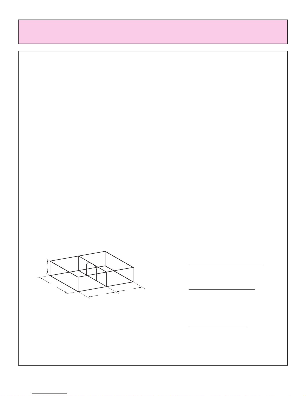
The folIowing formula can be used to determine the
maximum heater rating per the definition of
unconfined space:
BTU/HR=
(L1+L2)Ft
× (W)Ft × (H)Ft × 1000
50
Consider two connecting rooms with an open area
between, with the following dimensions:
BTU/HR=
(15
1
/2+12) × (12) × (8) × 1000
50
=52800 BTU/HR
If there is a door between the two rooms that can
be closed the calculation must be based only on the
room with the heater.
BTU/HR=
(15
1
/2) × (12) × (8) × 1000
50
=29760 BTU/HR
WARNING: If the area in which the heater may be operated is smaller than that defined as an
unconfined space or if the building is of unusually tight construction, provide adequate combustion and
ventilation air by one of the methods described in the National Fuel Gas Code, ANSI Z223.1/NFPA54,
Section 5.3 or applicable local codes.
- 6 -
INSTALLATION INSTRUCTIONS
W
H
L2
L1
Unusually tight construction is defined as construction where:
a) Walls and ceilings exposed to the outside atmosphere have a continuous water vapor retarder with a
rating of 1 perm (6×10
-11
kg per pa-sec-m2) or less with openings gasketed or sealed, and
b) Weather stripping has been added on openable windows and doors, and
c) Caulking or sealants are applied to areas such as joints around window and door frames, between
sole plates and floors, between wall-ceiling joints, between wall panels, at penetrations for plumbing,
electrical, and gas lines, and at other openings.
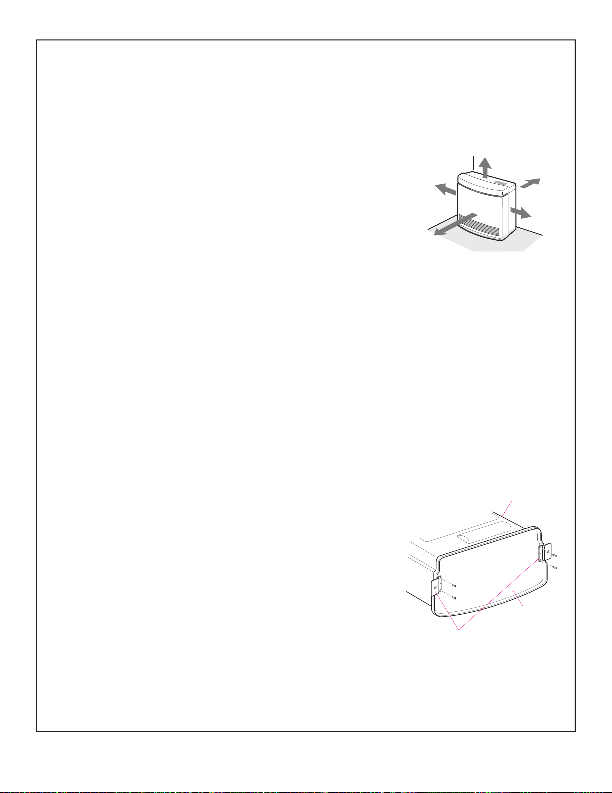
LOCATION AND CLEARANCES
1. The minimum clearances from the combustible materials are as follows:
40 inches from top
2 inches from back
2 inches from sides
30 inches from front
0 inches from bottom
2. This heater may be installed on combustible flooring. When the heater is installed directly on
carpeting, tile or other combustible material other than wood flooring, the heater shall be installed on
a metal or wood panel extending the full width and depth of the heater
.
3. Adequate clearances for accessibility for purposes of servicing and proper operation must be provided.
4. Adequate clearances around air openings must be provided.
5. Do not install this heater in bedrooms or bathrooms.
6. Right and left sides are determined when facing the front.
7. Do not install in areas where curtains, drapes, clothing, or other moving flammables are within 12
inches of this unit.
8. This unit is not designed to mount directly to a wall.
9. Make certain of adequate combustion and ventilation air.
10. Do not oversize the heater to the room.
GAS CONNECTION
1. Attach (2) floor fixing plates in the bottom of base plate
before gas connecting.
2. The gas supply line shall be gas-tight, sized and installed so as to
provide a supply of gas sufficient to meet the maximum demand of the
heater without loss of pressure.
3. A shut off valve (or appliance connector valve) should be installed in the upstream of the gas line to
permit servicing.
4. Flexible pipe and any appliance connector valve used for gas piping shall be types approved by
nationally recognized agencies.
- 7 -
40''
2''
2''
2''
30''
Base plate
Heater
Fixing plate
5. Any compound used on the threaded joint of gas piping shall be a type which resists the action of
liquefied petroleum gas.
6. Supplied gas pressure must be within the limits shown in the specifications.
7. After completion of gas pipe connections, all joints including the heater must be checked for gas-
tightness by means of leak detector solution, soap and water, or an equivalent nonflammable
solution, as applicable.
CAUTION: Since some leak test solutions, including soap and water, may cause
corrosion or stress cracking, the piping shall be rinsed with water after testing, unless
it has been determined that the leak test solution is noncorrosive.
8. The appliance and its appliance main gas valve must be disconnected from the gas supply piping
system during any pressure testing of that system at test pressures in excess of 1/2 psi (3.5kPa).
The appliance must be isolated from the gas supply piping system by closing its equipment shut-of
f
valve during any pressure testing of the gas supply piping system at test pressures equal to or less
than 1/2 psi (3.5kPa).
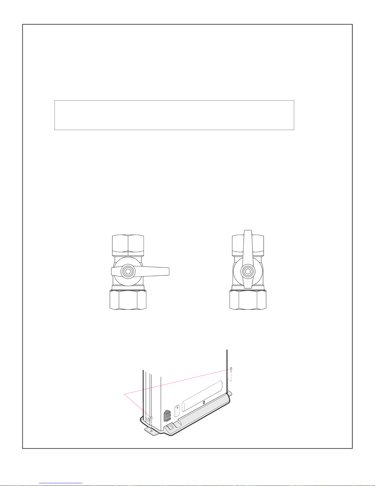
9. A valve supplied must be installed on back of unit at time of installation. This is for compliance to
ANSI standard Z21.11.2. Valve is packaged with unit.
MANUAL VALVE
10. After completing pipework, secure the heater to the floor.
Use the two screws provided,as shown in the drawing.
To prevent deforming floor fixing plate ,do not over torque screws.
- 8 -
OPENCLOSED
2 SCREWS
 Loading...