

Rinnai Neo RIB2312L, Neo RIB2312N Installation Manual
Neo
Installation guide
RIB2312N / RIB2312L
Appliance must be installed with a Rinnai approved flue
system.
This appliance shall be installed in accordance with:
- Manufacturer’s installation instructions
- AS/NZS 5601 Gas Installations
- AS/NZS 5263 Gas appliances standards
Installation, servicing and repair shall be carried out only
by authorised personnel.
Warning
Improper installation, adjustment, alteration, service or
maintenance can cause property damage, personal injury
or loss of life.
For more information about buying, using, and servicing
of Rinnai appliances call: 0800 RINNAI (0800 746 624).
Rinnai New Zealand Limited
105 Pavilion Drive, Mangere, Auckland
PO Box 53177, Auckland Airport, Auckland 2150
Phone: (09) 257 3800
Email: info@rinnai.co.nz
Web: www.rinnai.co.nz
www.youtube.com/rinnainz
www.facebook.com/rinnainz
Important:

cnt:
Checklist ............................................................... 4
Neo specification ................................................. 5
Inbuilt dimensions (mm) ...................................... 6
Freestanding dimensions (mm) ........................... 7
Gas supply and connection .................................. 8
Electrical connection ........................................... 9
Enclosure dimensions for inbuilt models ............. 10
Mantels and surrounds - inbuilt models only ....... 11
Clearances from combustibles ............................. 12
TV installation ....................................................... 14
Masonry installation ............................................. 16
Inbuilt mock chimney ........................................... 18
Freestanding installations .................................... 20
Log set and granule pack installation ................... 22
Inner frame and control panel .............................. 24
Commissioning .................................................... 25
Outer frame and dress guard ............................... 27
Flame pattern ....................................................... 28
Customer handover ............................................. 28
Wiring diagram ..................................................... 29
Flueing .................................................................. 30
4 | Neo RIB2312 installation guide: 12148-A 01-17
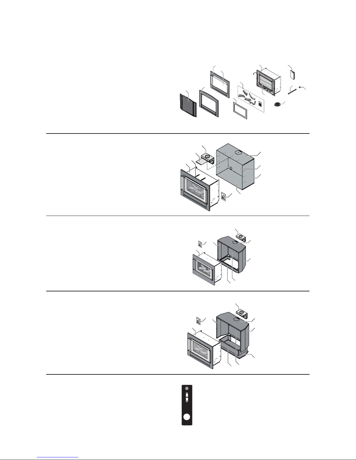
Checklist
Engine: Masonry installations
1. Rinnai Neo heater (engine)
2. Outer frame (standard or classic)
3. Glass outer dress guardstandard frame
Mesh dress guardclassic frame (inbuilt models)
4. Inner frame
5. Log set and granule pack (inside appliance)
6. Semi rigid stainless steel gas pipe
7. Flared brass adaptor “ UNF - ½ “ BSPT
8. Foam sealing strip
9. Operation and installation guides
Standard
frame
Classic
frame
12
2
3
4
5
5
6
7
8
3
9
Inbuilt mock chimney installations
A. Engine set (see above)
1. Spigot adaptor
2. Spigot guide panel
3. Spigot guide rails
4. Zero clearance box top panel
5. Zero clearance box rear panel
6. Zero clearance box left and right panels
7. Zero clearance box base panel
8. Hardware pack
A
3
7
2
1
8
5
6
4
Freestanding console installations
A. Engine set (refer masonry installation)
1. Spigot adaptor
2. Console top panel
3. Console right side panel
4. Console left side panel
5. Console rear panel
6. Console pillar
7. Hardware pack
1
A
3
2
7
4
5
6
Freestanding plinth installations
A. Engine set (refer masonry installation)
1. Spigot adaptor
2. Plinth top panel
3. Plinth right side panel
4. Plinth left side panel
5. Plinth rear panel
6. Plinth pillar
7. Plinth base
8. Hardware pack
1
A
3
2
4
5
6
7
8
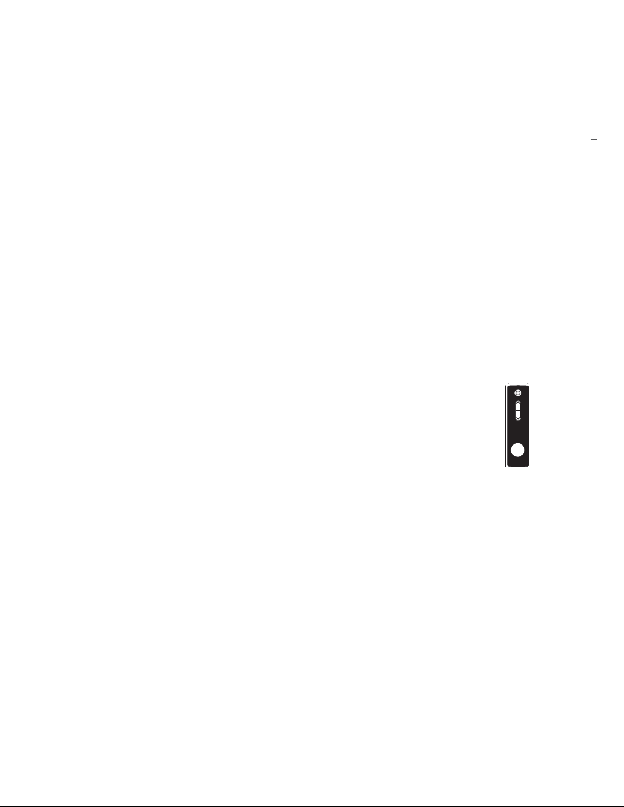
Infra-red remote control
Infra-red remote control (batteries inserted).
Remote comes as standard and will come with
the Neo engine.
23
Neo RIB2312 installation guide: 12148-A 01-17 | 5
Neo Specication
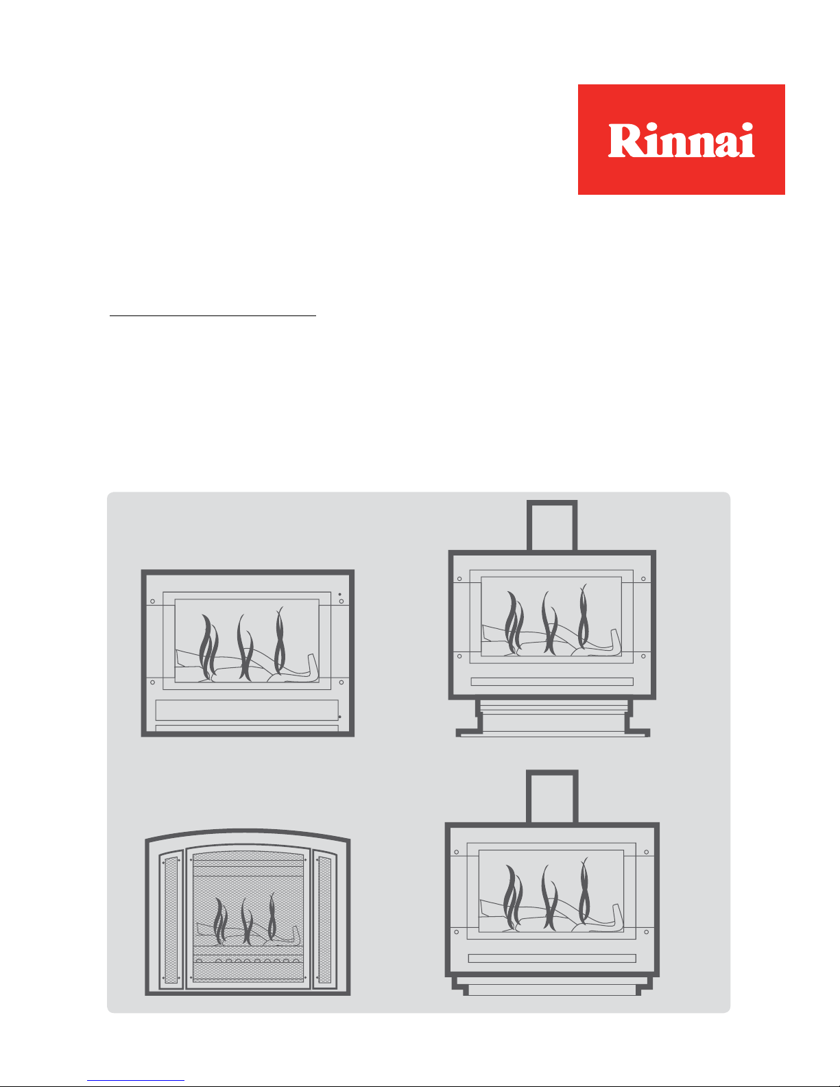
Natural draft burning log effect inbuilt gas fire
with glass front and convection fan. Different
frame options available.
Specification summary
Input = 14-30 MJ/h*
Output = 2.98-6.94 kW*
Efficiency = 80%
Heating area = 69-107 m
2
**
Gas type = NG or ULPG
* Will vary according to gas type and flue configuration
** Will vary depending on geographical location in NZ
Suitability
- Inbuilt masonry
- Inbuilt mock chimney
- Freestanding
The Neo is not suitable for areas where painting
is taking place, or in places such as hairdressing
salons, where there may be fluff and dust, and
where aerosols are used. The inbuilt Neo gas
fireplace models are not designed to be built into
bookcases.
Installation considerations
The Neo draws air for combustion from the room.
Adequate ventilation must be calculated and
provided by the gasfitter as per AS/NZS 5601.1.
Burn media
Driftwood log set comes as standard.
Convection fan
Fan forced 2-speed convection fan (low and high).
Heat is distributed from the top of the appliance.
Data plate
Inside appliance on the front left hand side.
Gas connection
½ “ BSPT (flexi). The gas supply terminates inside
the heater at the lower front right hand side of the
appliance.
Ignition
Continuous spark electronic ignition.
Noise level
37-45 dB(A)
Flue (masonry)
The Neo must be installed with a Rinnai flexiliner
flue (Ø 100 mm).
Flue (mock chimney and freestanding)
Appliance must be installed with a Rinnai flue
system. Inner 100 mm, outer 150 mm.
Power consumption and electrical supply
High = 50 W
Standby = < 3 W
Comes with a 1.5 m power cord and 3-pin plug.
The standard electrical connection is to the rear
left of the appliance, but can pass through the left
or right by removing the knockout tab from the
bottom edge of the front panel.
Safety devices
Overheat switch, electrical fuse, and flame failure
sensing system.
Temperature control
Once the unit is turned on the infrared remote* is used to control the
flame height and heat output.
If the remote is not used the Neo
will automatically modulate between
the burner settings to maintain the
default set temperature of 22 °C.
* Temperature sensor is located in the bottom of the
remote.
Weight
60 kg
23
136 mm
34 mm
depth - 11 mm
6 | Neo RIB2312 installation guide: 12148-A 01-17
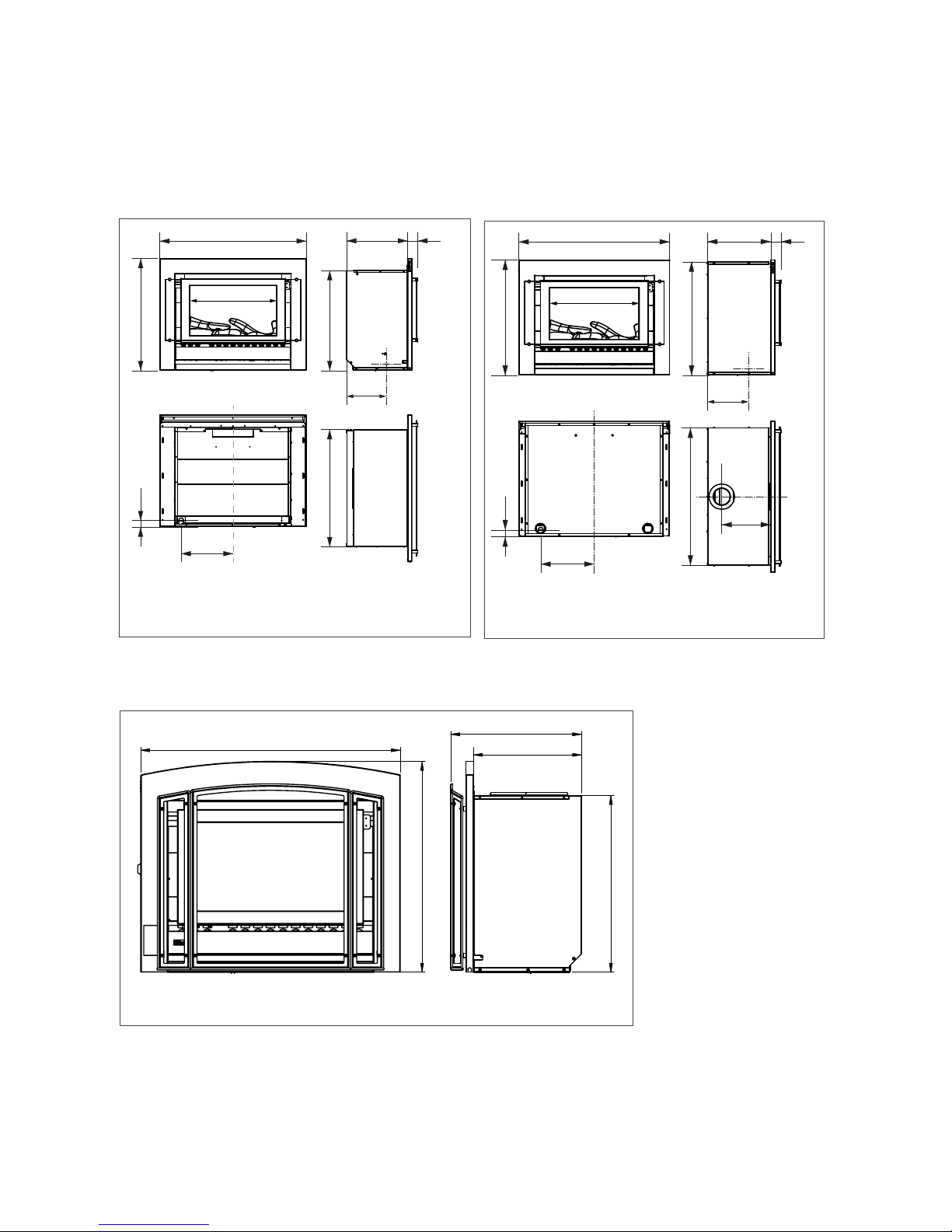
Inbuilt dimensions (mm)
includes the frame
Neo Inbuilt masonry
865
660
359 62
691 589
235
305
45
510
703
865
590
359
436
865 363 62
660
650
240
795
280
45
305
510
The above dimensions INCLUDE the zero
clearance box.
Neo Inbuilt mock chimney
Neo Inbuilt Premium Classic
The above dimensions INCLUDE the zero clearance box.
Neo RIB2312 installation guide: 12148-A 01-17 | 7
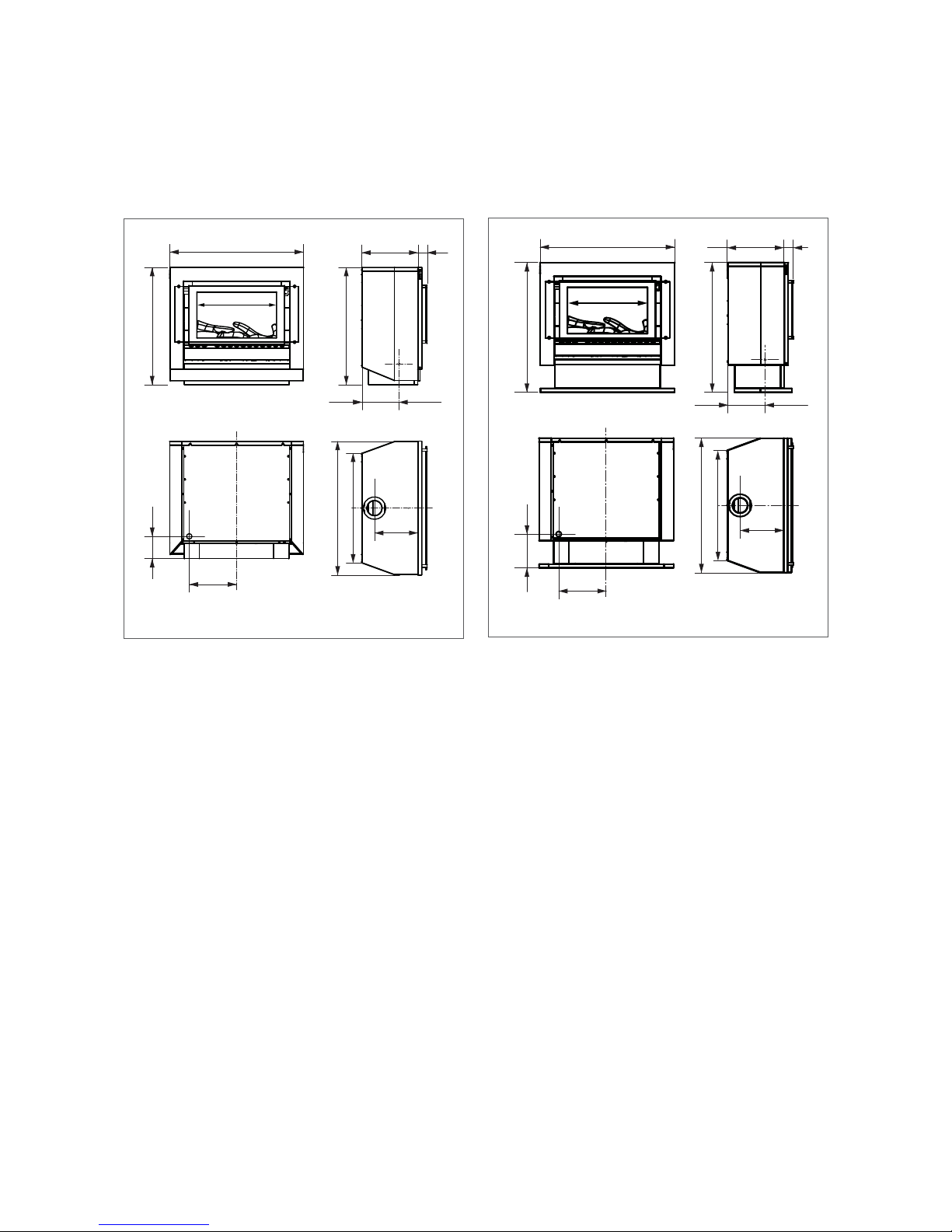
865
865
760
280
760
305
140
235
363 62
712
510
865
865
837
280
305
215
235
363 62
837
712
510
Freestanding dimensions (mm)
includes the frame
Freestanding console
Freestanding plinth
8 | Neo RIB2312 installation guide: 12148-A 01-17
Gas supply and connection
Gas pipe sizing must consider the gas input to this appliance as well as all other gas appliances in the
premises. The gas meter and regulator must be specified for the total gas rate. An approved sizing
chart such as the one in AS/NZS 5601.1 should be used.
The gas supply termination is inside the
heater and enters through the rear of the appliance.
Gas supply location
1. Mark off the location for the vertical centre line of the
heater enclosure.
2. To the right of the vertical centre line, mark off the vertical
2 and horizontal 3 locations for the gas supply penetration.
2
Gas supply locaon
3
INBUILT FREESTANDING
Masonry Mock chimney Console Plinth
305 mm to right of the
appliance centre line
305 mm to right of the
appliance centre line
305 mm to right of the
appliance centre line
305 mm to right of the
appliance centre line
35 mm from base of
enclosure
35 mm from base of
enclosure
140 mm from floor level 215 mm from floor level
Terminate 230 mm from
front of enclosure
Terminate 230 mm from
front of enclosure
Terminate at wall,
clearance plus 155 mm
Terminate at wall,
clearance plus 155 mm
5
W
A
L
L
4
M
in
im
u
m
c
le
a
r
a
n
c
e
7
5
m
m
Back of heater
F
R
O
N
T
O
F
E
N
C
L
O
S
U
R
E
RE
AR
O
F
E
NCL
O
S
UR
E
4
STEP 1
Inbuilt installations
STEP 2
Freestanding installations
The length of the gas supply termination
is measured from the front of the
enclosure.
The length of the gas supply termination
is measured from the back of the heater
plus 155 mm.
Installer to terminate to suit, and fit
supplied gas connection . Leak test the
joint between the flexible gas connection
and termination.
Gas connection
Firmly grasp the stainless steel flexi pipe
and bend to line up with the gas control
valve inlet, then attach the pipe to the gas
control valve and tighten.
The use of a rubber hose for
any gas connection to a fixed
appliance is NOT authorised by the
manufacturer.
IMPORTANT
Neo RIB2312 installation guide: 12148-A 01-17 | 9
Electrical connection
The Neo is supplied with a power cord (length 1500 mm) and a 3-pin plug. The
standard electrical connection passes through the rear panel, but can also pass
through the left or right hand side of the unit by removing the knockout tab from
the bottom edge of the front panel. If changing the electrical position use the
rubber grommet from the rear of the appliance for cable protection.
The connection is either direct wired* or
connected to a power point within the cavity. This
must be connected to a dedicated 240 V, 10 A
earthed power point. The electric isolation switch
must be accessible after the appliance has been
installed.
The heater must not be located immediately below
a socket outlet (potential fire hazard).
The power cord is not fire rated and should not
come into contact with the unit. If the power cord
is damaged, it must be replaced by a licensed
tradesperson. This must be a genuine replacement
part available from Rinnai.
* Consult a qualified electrician if direct wiring is required as it must comply with AS/NZS 5601 and AS/NZS 3000 and other
relevant local regulations
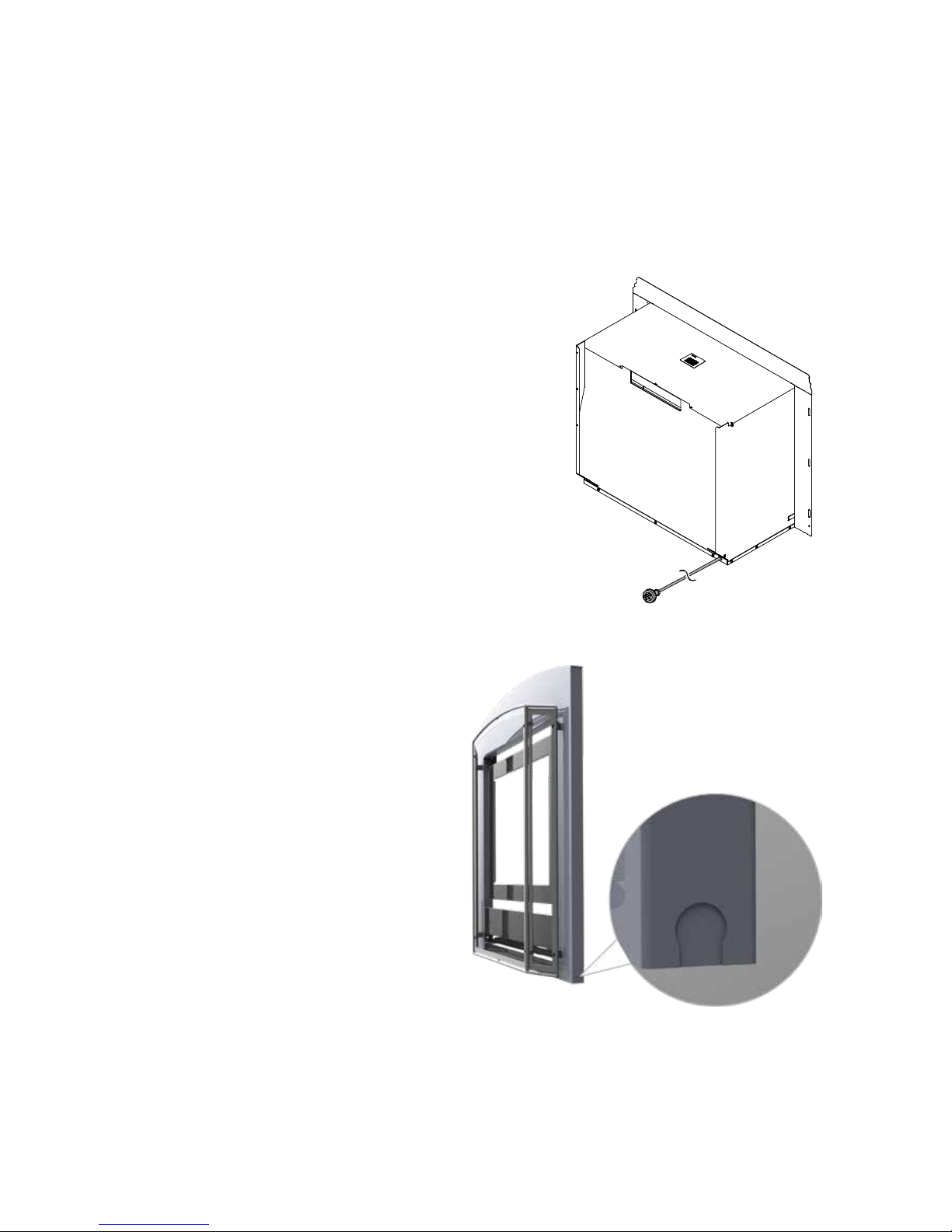
Using existing externally mounted power points on inbuilt installations
If you already have an existing power
point outside the enclosure, you can
redirect the power cord and plug through
the LHS or RHS of the front panel. With
the frame removed redirect the cord and
plug (with the grommet), underneath the
unit and to the front (left or right).
Remove the pre-punched metal knockout located in the lower left or right edge
of the frame. Refit the cord and plug to
the frame, ensuring the grommet is fitted
to the metal knock-out. Excess cord may
be left in the cavity below the unitDO
NOT coil excess cord.
Electrical knock-out position on a Neo frameknockout is on both sides of the frame.
10 | Neo RIB2312 installation guide: 12148-A 01-17
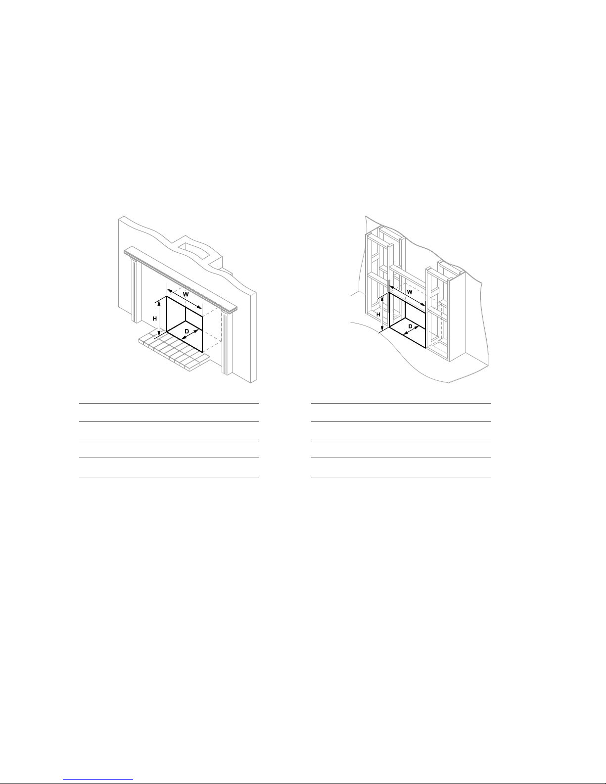
Enclosure dimensions for inbuilt models
The main points governing location are flueing and warm air distribution. The
enclosure dimensions provided are critical to the installation of this appliance and
must be adhered to.
The heater must be positioned on a flat level surface that allows free movement of
the appliance.
Inbuilt masonry installations Inbuilt mock chimney installations
Inbuilt masonry
W-width 695 mm
H-height 600 mm
D-depth 370 mm
Use a slurry of sand and cement to level the
base as required.
Inbuilt mock chimney
W-width 800 mm
H-height 655 mm
D-depth 370 mm
The zero clearance box needs to be supported
within the enclosure. Either construct a base
using board with supporting joists or support
with the frame itselfmust be capable of
supporting a minimum of 1.5 times the weight
of the appliance.
Important
The total cavity depth MUST also include the
thickness of the external cladding as the zero
clearance box MUST BE installed flush with the
cladding surface to ensure alignment of the
flue.
Neo RIB2312 installation guide: 12148-A 01-17 | 11
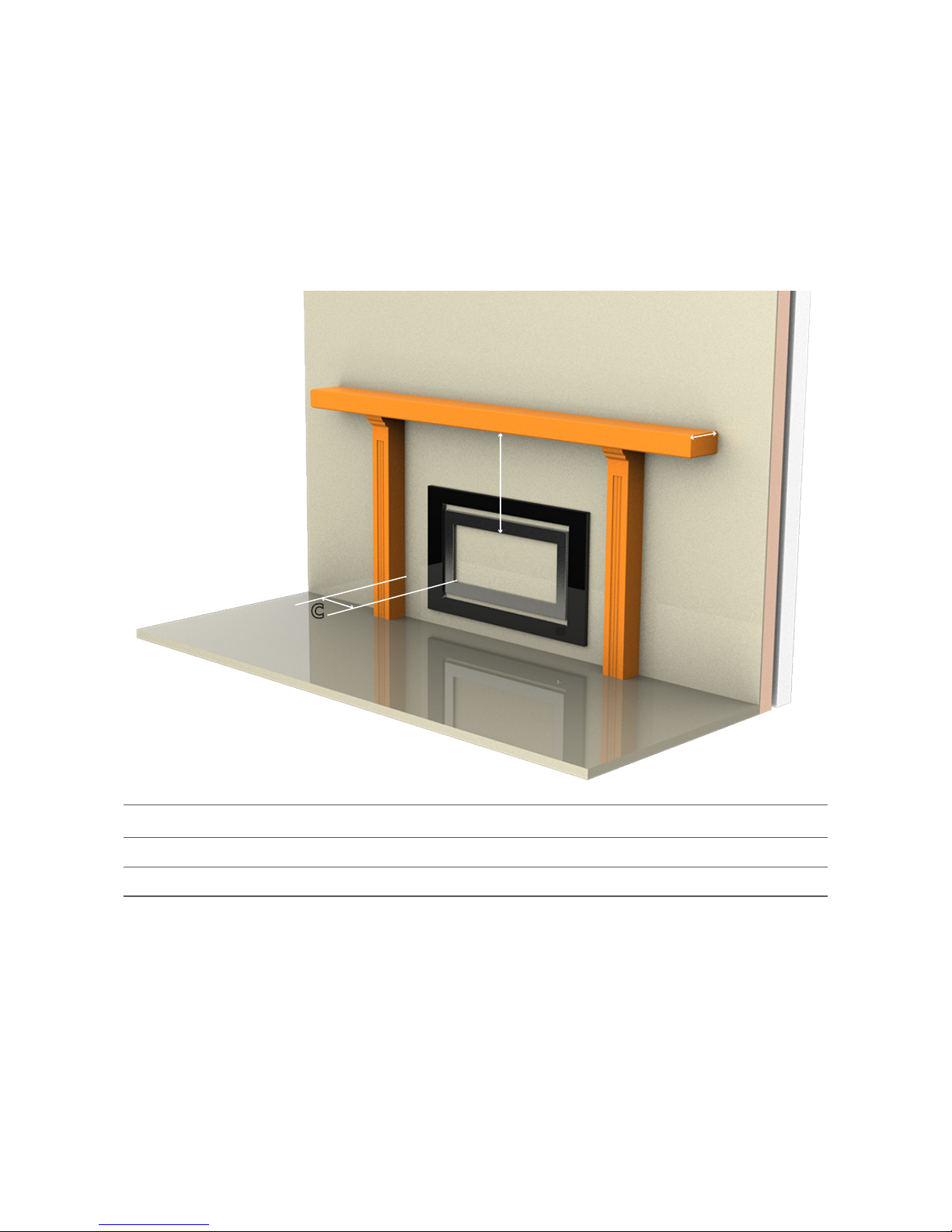
Mantels and surrounds - inbuilt models only
Combustible mantels and surrounds require clearance from the unit to minimise
the risk of fire. Mantels and surrounds, made of combustible materials such as
wood, are allowed providing they are outside the minimum clearances shown.
The Neo gas fireplace is not designed to be built into bookcases.
A
B
C
A Mantel needs to be a minimum of 400 mm away from the edge of the inner glass.
B Maximum mantel depth at 400 mm (A) is 250 mm.
C Surround needs to be a minimum of 400 mm away from the edge of the inner glass.
For every 50 mm of added mantel depth there must be an additional 100 mm of clearance from
the edge of the inner glass.
For example:
Mantel depth
a
: clearance required
300 mm 500 mm
350 mm 600 mm
400 mm 700 mm
 Loading...