

Rinnai Neo RIB2310N, Neo RIB2310L Installation Manual

NEO
Installaon Manual
Appliance must be installed, commissioned and serviced by a licensed tradesperson in
accordance will all applicable local rules and regulations.
For installations into a combustible opening, a Rinnai zero clearance box and ue kit are
mandatory.
Before installation:
• Unpack the appliance and components and check for damage—DO NOT install any
damaged items
• Check all components have been supplied and that you have the correct gas type
• Read these instructions to get an overview of the steps required before starting the
installation
Failure to follow these instructions could cause a malfunction of the appliance. This could result
in serious injury and property damage.
RIB2310N
RIB2310L
Contents
WARNING
Improper installaon, adjustment, alteraon, service or maintenance can cause
property damage, personal injury or loss of life.
For assistance or addional informaon contact Rinnai on 0800 RINNAI
(0800 746 624).
Checklist 3
Specication 4
Dimensions 5
Location 6
Enclosure dimensions 9
Gas supply 10
Flueing options and components 11
General ueing information 12
Masonry installations 14
Mock chimney installations 16
Freestanding installations 18
Log set installation 20
Granule pack installation 21
Test pressures 22
Checking the ame pattern 24
Fitting the frame assembly 25
Commissioning 26
Wiring diagram 27
Rinnai New Zealand Limited Neo Installation Manual: 11906-B
02-11
3
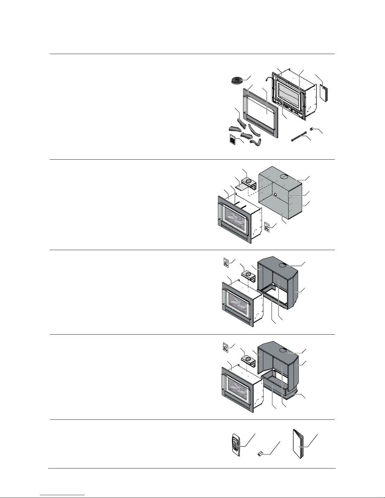
Checklist
Engine - masonry installation:
1. Rinnai Neo heater (engine)
2. Outer (attached to heater with 2 x 8 g black screws)
3. Glass outer dress guard
4. Inner frame
5. Log set (inside appliance)
6. Packet of burner granules
7. Semi rigid stainless steel gas pipe with 5/8 " UNF are connection
8. Flared brass adaptor 5/8 " UNF - ½ " BSPT
9. Foam sealing strip
10. Operation and installation manual
7
8
6
5
9
2
3
1
4
5
10
Inbuilt mock chimney installation:
A Engine set (see above)
1. Spigot adaptor
2. Spigot guide panel
3. Spigot guide rails
4. Zero clearance box top panel
5. Zero clearance box rear panel
6. Zero clearance box left and right panels
7. Zero clearance box base panel
8. Hardware pack
A
3
7
2
1
8
5
6
4
Freestanding console installation:
A Engine set (refer masonry installation)
1. Spigot adaptor
2. Console top panel
3. Console right side panel
4. Console left side panel
5. Console rear panel
6. Console pillar
7. Hardware pack
1
A
3
2
7
4
5
6
Freestanding plinth installation:
A Engine set (refer masonry installation)
1. Spigot adaptor
2. Plinth top panel
3. Plinth right side panel
4. Plinth left side panel
5. Plinth rear panel
6. Plinth pillar
7. Plinth base
8. Hardware pack
1
A
3
2
4
5
6
7
8
Remote/thermostat - comes with all ETR models
1. RF combination remote/thermostatic control with wall mount
2. AA batteries (x2)
3. Operation manual
1
2
3
Rinnai New Zealand Limited Neo Installation Manual: 11906-B
02-11
4
Specicaon
Description • Inbuilt gas space heater
• Burning log eect
• Glass front with glass dress guard
• Convection fan, top air discharge
Installation Inbuilt masonry, inbuilt mock chimney, and freestanding options
Combustion Method Bunsen type burner
Data Plate Inside appliance on the front left hand side
Flue - Masonry Rinnai strongly recommends the use of a Rinnai exiliner ue system (exi Ø 100 mm).
Failure to meet this criteria may result in an unsafe situation.
Installation without a exiliner ue is permissible as long as the chimney is checked for
soundness and ability to achieve a good draw. Terminal 240 mm x 45 mm rear discharge
(spigot).
Flue - Decorative
(mock chimney) and
Freestanding
Natural draft twin skin ue. An approved 100 mm cowl must be tted to all installations.
Decorative chimney installations require a Rinnai zero clearance box and zero clearance
ue kit.
Flue dimensions:
• Outer - 150 mm
• Inner - 100 mm
Gas Connection
½ " BSPT, the gas supply terminates inside the heater at the front lower right hand side
of the appliance
Gas Type NG and General Product LPG
Convection Fan 2-speed centrifugal, double diameter 160 x 180 mm
Heating Area • Up to 107 m
2
(NG)
• Up to 93 m2 (ULPG)
Ignition Continuous spark electronic ignition
Input/Output
Input NG: 14-30 MJ/h
Input ULPG: 14-27 MJ/h
Output NG: 3.24-6.94 kW
Output ULPG: 2.98-6.04 kW
Noise Level 37-45 dB(A)
Power Consumption High 50 W
Standby <3 W
1500 mm cord is supplied with 3-pin plug on the rear left of the appliance
Safety Devices Overheat switch, electrical fuse, ame failure sensing system, and power failure
protection
Temperature Control
Manual models, manual control on unit
ETR models, thermostatic, temperature control range 7-32 °C
Thermal Eciency NG - 80.5%
ULPG - 80%
Eciency star rating: 4.10 stars
Weight 60 kg
Rinnai New Zealand Limited Neo Installation Manual: 11906-B
02-11
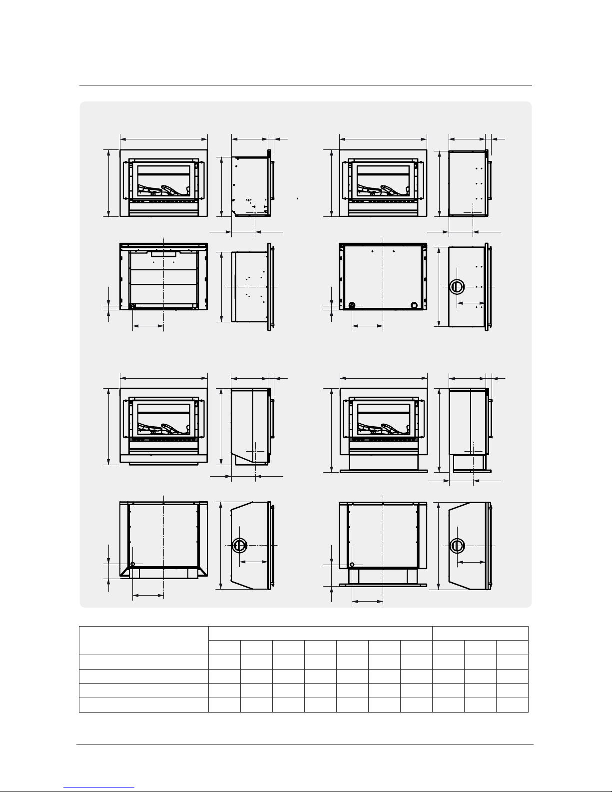
5
A A
AA
E
E
E
E
BB FF
BB
G
G
G
C D
C D
C D
C D
FF
H H
H
H
II
I
I
J J
J
J
Inbuilt masonry Inbuilt mock chimney
Freestanding console Freestanding plinth
Dimensions (mm)
Model External dimensions Gas connection
A B C D E F G H I J
Inbuilt masonry 865 660 359 62 691 589 - 305 45 235
Inbuilt mock chimney 865 660 363 62 795 650 280 305 45 240
Freestanding console 865 760 363 62 865 760 280 305 140 235
Freestanding plinth 865 837 363 62 865 837 280 305 215 235
Rinnai New Zealand Limited Neo Installation Manual: 11906-B
02-11
6
Locaon
The main points governing location are ueing and warm air distribution. The heater must not
be installed where curtains or other combustible materials could come into contact with the
appliance. In some cases curtains may need restraining. The Neo gas replace is not designed
to be built into bookcases.
Standard ued appliances draw the air for combustion from the room itself so there is a need
for xed ventilation. Fixed ventilation must be provided as per NZS 5261.
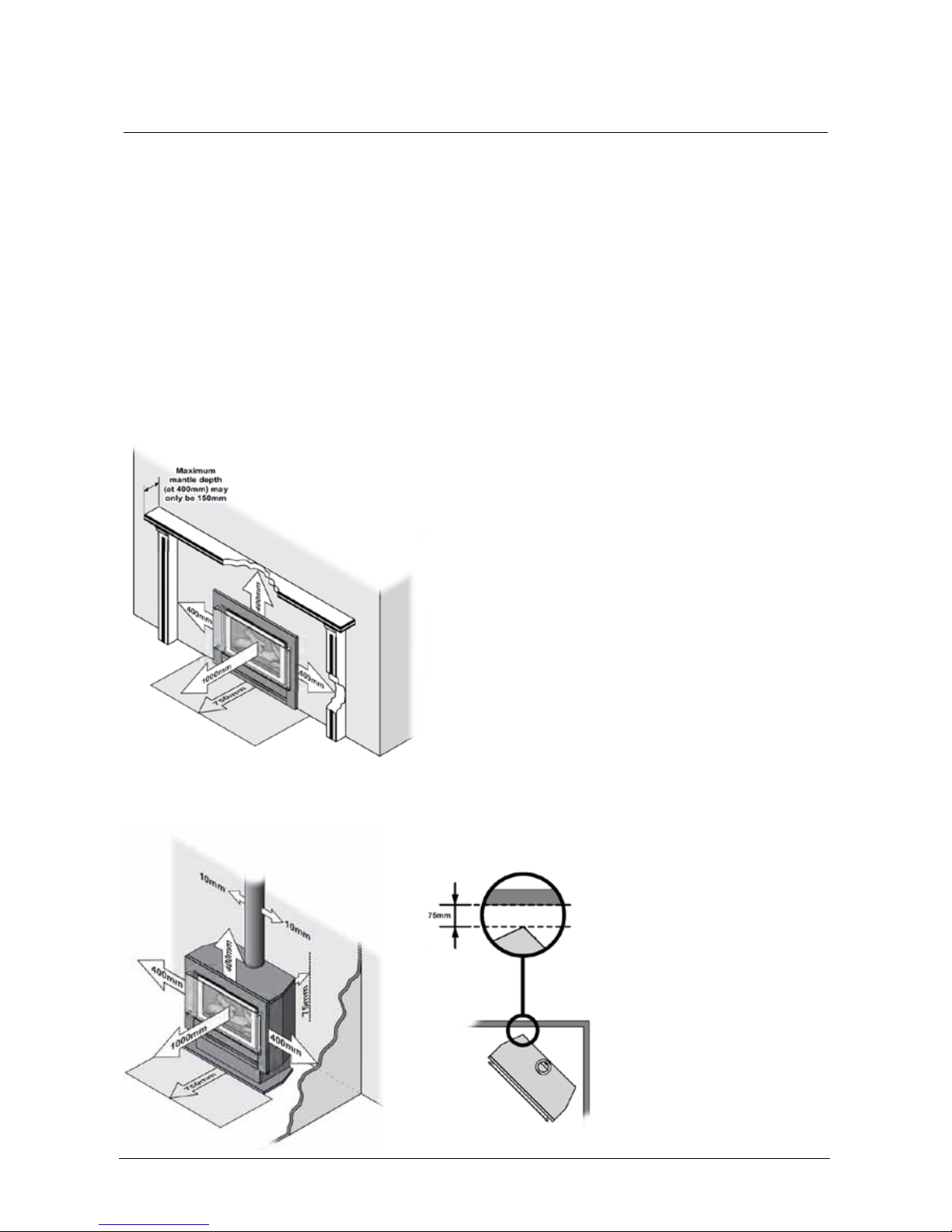
Clearances
The clearances listed below are minimum clearances unless otherwise stated.
Inbuilt models
Freestanding models (can be posioned directly on the oor)
Rinnai New Zealand Limited Neo Installation Manual: 11906-B
02-11
7
Locaon
Mantels, surrounds, and hearths for inbuilt installaons
A mantel and surround are allowed providing they are outside the minimum clearances shown
on the previous page.
Minimum clearance
The minimum clearance from the top of the appliance is 400 mm. The depth of the mantel/
surround at this minimum clearance must not exceed 150 mm.
Additional mantel/surround depth
For every 50 mm of added mantel depth/surround, there must be an additional 100 mm of
clearance. For example; a 200 mm mantel depth will require a 500 mm clearance from the top
of the appliance.
Hearths
A hearth is not necessary but can be used for decorative purposes or protection of sensitive
ooring if required. It must not obscure the front of the re.
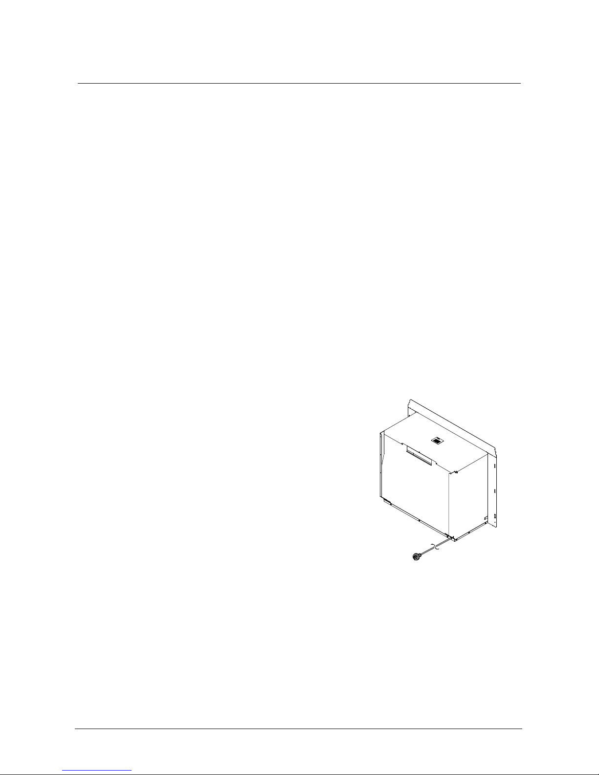
Electrical connecon
The Neo is supplied with a power cord (length 1500 mm)
and a 3-pin plug. The standard electrical connection passes
through the rear panel, but can also pass through the left
and right hand side of the unit by removing the knockout
tab from the bottom edge of the front panel. If changing
the electrical position use the rubber grommet from the
rear of the appliance for cable protection.
Rinnai recommend the heater is plugged into a dedicated
240 V, 10 A earthed power point. The power point must not
be located above the heater (potential re hazard). If the
supplied plug and power cord is to be used with an external
power point then the power cord will need to be tted with
the supplied grommet.
A suitable means of electric isolation must be provided which is adjacent to the appliance and
accessible with the appliance installed.
The electrical cord is not re rated and should not come into contact with the unit. If the
supply cord is damaged, it must be replaced by a licensed tradesperson. This must be a genuine
replacement part available from Rinnai—part number 6765B.
Rinnai New Zealand Limited Neo Installation Manual: 11906-B
02-11
8
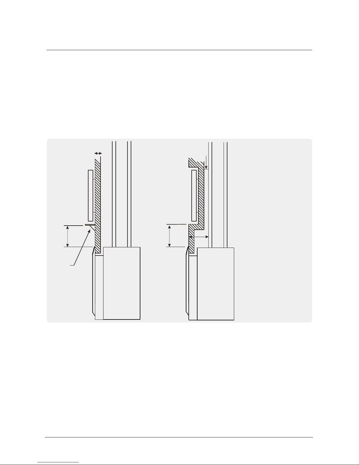
Locaon
TV installaon above a replace
If installing a at screen TV above the re the main issue is heat. Heat from the re and heat
from the ueing components that sit behind the TV, especially if recessed.
The Neo gas res have a fan that distributes warm air from the top of the appliance out into
the room. As warm air is dispersed outwards as opposed to directly upwards, installation of a
TV may be an option. The diagram below outlines recommended minimum clearances when
installing a TV directly above the Neo inbuilt models. All dimensions are in millimetres.
Mantel
400
TV
Rinnai
Neo Inbuilt
400
75
200
20
Flue
Flue
TV
Rinnai
Neo Inbuilt
The 400 mm dimension is the
minimum clearance required
to combustibles and to a
mantel.
For a TV mounted directly
above the Neo, the mantel
must be at least the depth
of the TV to deect the heat
away from the appliance.
It is up to the customer to check the TV installation instructions with the TV supplier to verify
clearances. Some TV manufacturers have warranty conditions that state a TV is not to be
installed above a replace.
Rinnai does not accept any responsibility for damage to a TV resulting from the use of this
information.
Rinnai New Zealand Limited Neo Installation Manual: 11906-B
02-11
9
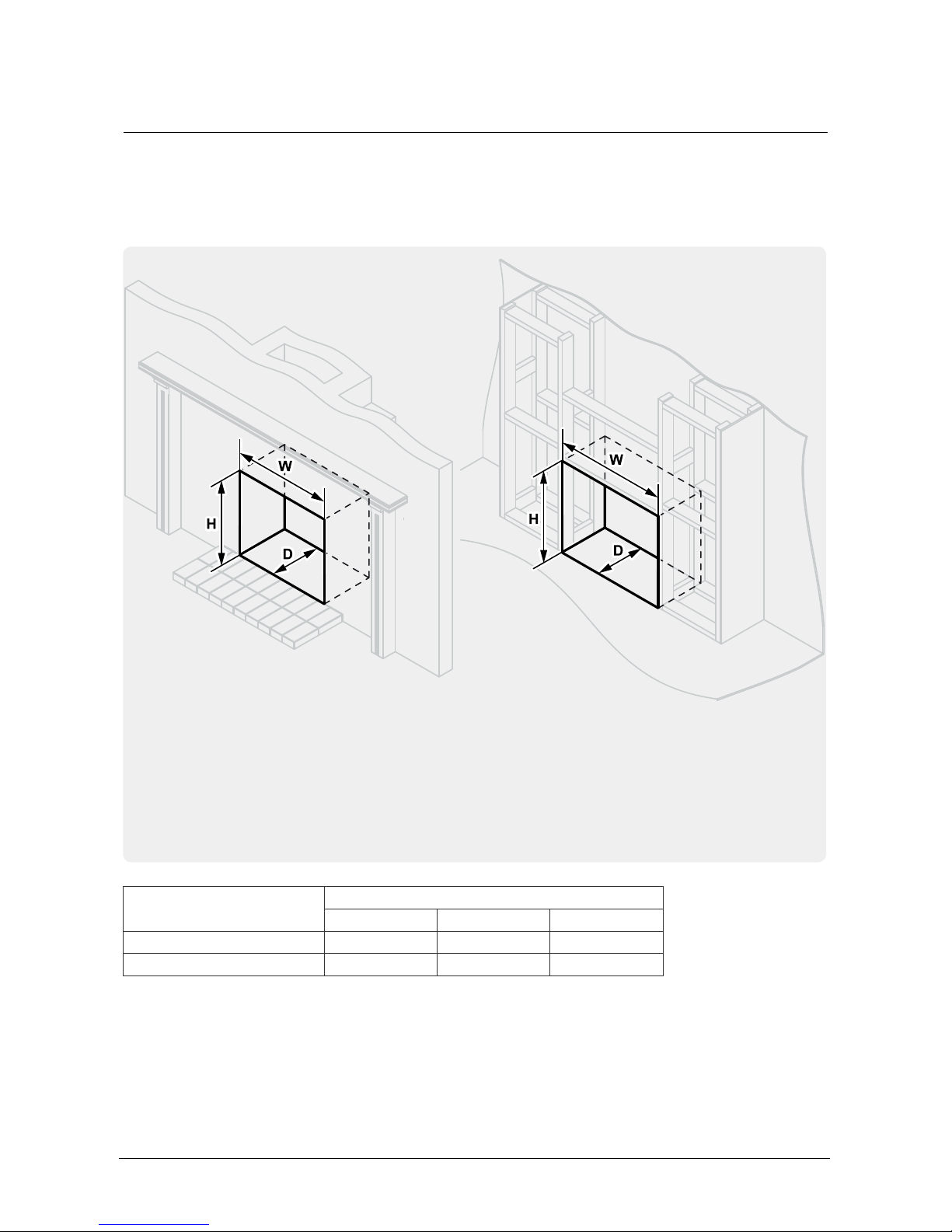
Enclosure dimensions
The enclosure dimensions specied are critical to the successful installation of this appliance.
The appliance must be positioned within the enclosure on a at level surface. If the appliance is
to be elevated from the ground, a base must be constructed with supporting joists capable of
supporting a minimum of 1.5 times the weight of the appliance.
Model Minimum dimensions (mm)
Height (H) Width (W) Depth (D)
Inbuilt masonry 600 695 370
Inbuilt mock chimney 650 800 370
Inbuilt masonry installaons Inbuilt mock chimney installaons
Important
The total cavity depth MUST also include the
thickness of the external cladding as the zero
clearance box MUST BE installed ush with the
cladding surface to ensure alignment of the
ue.
 Loading...