

Page 1
Wireless Controller
Installation Instructions
To the Installer
The wireless controller can only be used with
Serial NO.Model
C85i
R85e
R70e
R53i / C53i
R53e / C53e
R42e / C42e
To correctly and safely install this product, please read this document carefully before
installation.
After installation is complete, explain to the customer how to use the device according
to the Wireless Controller Manual.
Name
05.05 - 117257
05.05 - 117257
05.05 - 110434
05.05 - 109539
05.05 - 000001
05.05 - 000001
Model
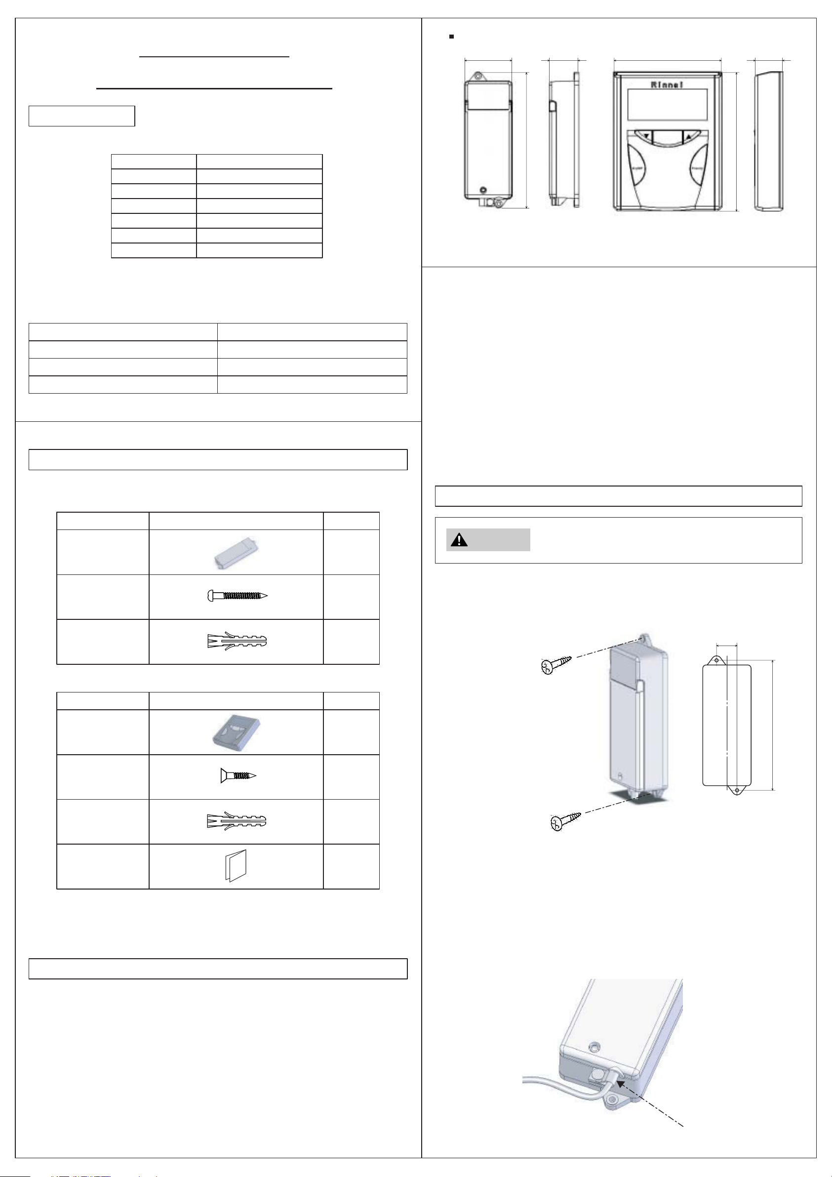
External Dimensions Diagram (units: inches and mm)
2.28"(58) 1.38"(35) 4.33"(110)
6.57"(167)
MC-502RC-1US-M
(Transceiver)
Transceiver
• The top of the transceiver should be higher than the top of the water heater because
the antenna is in the top of the transceiver.
• Install the transceiver in a location that is accessible for servicing.
MC-502RC-1US-S
(Wireless Controller)
1.16"(29.5)
5.90"(150)
Transceiver
Wireless Controller
Transceiver and Wireless Controller
MC-502RC-1US-M
MC-502RC-1US-S
MC-502RC-1US-MS
Parts List
Confirm that the following parts are included for your product.
(1) MC-502RC-1US-M
Part name
Transceiver
Screw
Appearance
Qty
1
2
Wireless controller
• Do not install the wireless controller on a table or in a drawer. The wireless controller
is designed to be used in the holder which is attached to a wall.
• Select a location for the wireless controller where the liquid crystal display can be
easily read (i.e. away from direct sunlight).
• Do not install either component in a location where there is a lot of hydrogen sulfide
or ammonia.
• Do not install either component where water may constantly splash on it.
Transceiver Installation
To prevent electric shock or damage to the appliance,
WARNING
(1) Attach the transceiver to the wall with two screws. Use the anchors with the
screws if installing on a concrete wall or sheetrock. Do not over tighten. Do not
tighten using a powered screwdriver.
disconnect the power to the water heater before installing
the transceiver.
Anchor
(2) MC-502RC-1US-S
Part name
Wireless
Controller
Screw
Anchor
Wireless
Controller
Manual
(3) MC-502RC-1US-MS includes all of the parts in MC-502-1US-M (transceiver) and
MC-502RC-1US-S (wireless controller).
Appearance
2
Qty
1
2
2
1
0.98"(25)
• Position transceiver
• Mark and drill holes (ø1/8")
• If necessary place anchors
in hols (ø3/16")
• Position transceiver and screw in
(2) Connecting the communications cable to the transceiver
- Remove the screw in order to open the cover.
- Remove the screw from the cable clamp at the bottom of the transceiver.
- Attach the communications cable to both terminals inside.
- Position the cable through the hole in the bottom of the transceiver and secure
with the cable clamp. The cover should be able to close. The screw will be
installed in the cover after you have set the maximum temperature in step
[Set the Maximum Temperature].
6.18"(157)
Installation Location
• The installation must conform with local codes.
• The distance between the transceiver and the water heater should be less than 65
feet (20 meters).
• In order for the wireless controller to communicate with the transceiver do not install
either unit in an enclosure surrounded by metal. Do not install the wireless controller
or transceiver where metal appliances would block their signals.
• Do not install the transceiver or wireless controller where there are strong magnetic
fields.
• Do not install the transceiver or the wireless controller in a high temperature area.
• Do not install either component in a location where there is a lot of hydrogen sulfide
or ammonia.
• Do not install either component where water may splash on it.
clamp
Page 2
Connecting the Transceiver to the Water Heater
Set the Maximum Temperature
Refer to the water heater owner’s manual. Connections will be made using the
quick cable connector or the PC Board depending on your model.
In Case of The Quick Cable Connector
Cut the communication cable to the appropriate length.
In Case of PC Board
CABLE
Set the maximum temperature on the transceiver by pressing the Max Temp button.
Pressing repeatedly will cycle through the temperatures shown below. On residential
units the maximum temperature is 140° F and on commercial units the maximum
temperature is 185° F.
Choosing a lower maximum temperature will limit your available temperatures at the
wireless controller. The maximum temperature on the transceiver will have no effect
on the wired controllers (MC-91-1US, MC-100V, and BC-100V).
Install the screw in the cover.
CLAMP
Wireless Controller Initialization
To enable communication, each wireless controller
needs to be initialized with the transceiver. Up to 4
wireless controllers can be initialized with the
transceiver.
When installing different types of controller, install the
wired controllers before initializing the wireless
controllers.
1. Insert the batteries
• Check the polarity
• Use new 4 AA batteries
• Do not mix old and new batteries
• When installed the display will light up momentarily as shown in screen A and
then the display will show screen B.
2. Turn on the power supply to the water heater.
3. At the transceiver, press and hold the “Entry” button until the No. indicator starts
to flash (about 3 seconds). The figure of the transceiver shows the No. 1 light as
an example.
4. On the wireless controller, press and hold the “ON/OFF” button until the display
shows the “-0” as in Screen C (about 2 seconds).
5. On the wireless controller, press the “ON/OFF” button once to start initialization.
This will take a few seconds.
6. Once the components are initialized then the No. button on the transceiver will
stop flashing and light continuously; and the wireless controller display will show
normal indications as in Screen D.
7. To erase the initialization of a wireless controller, press the appropriate No. button.
The light will turn off. The wireless controller will display the out of communication
indicator.
135
130 125 120 115 110 108 106 104
140 150 160 185
NOTE: It may appear that you are able to set the maximum temperature higher than
140° F on a unit but the PC Board will override the setting on the transceiver and only
allow 140° F maximum.
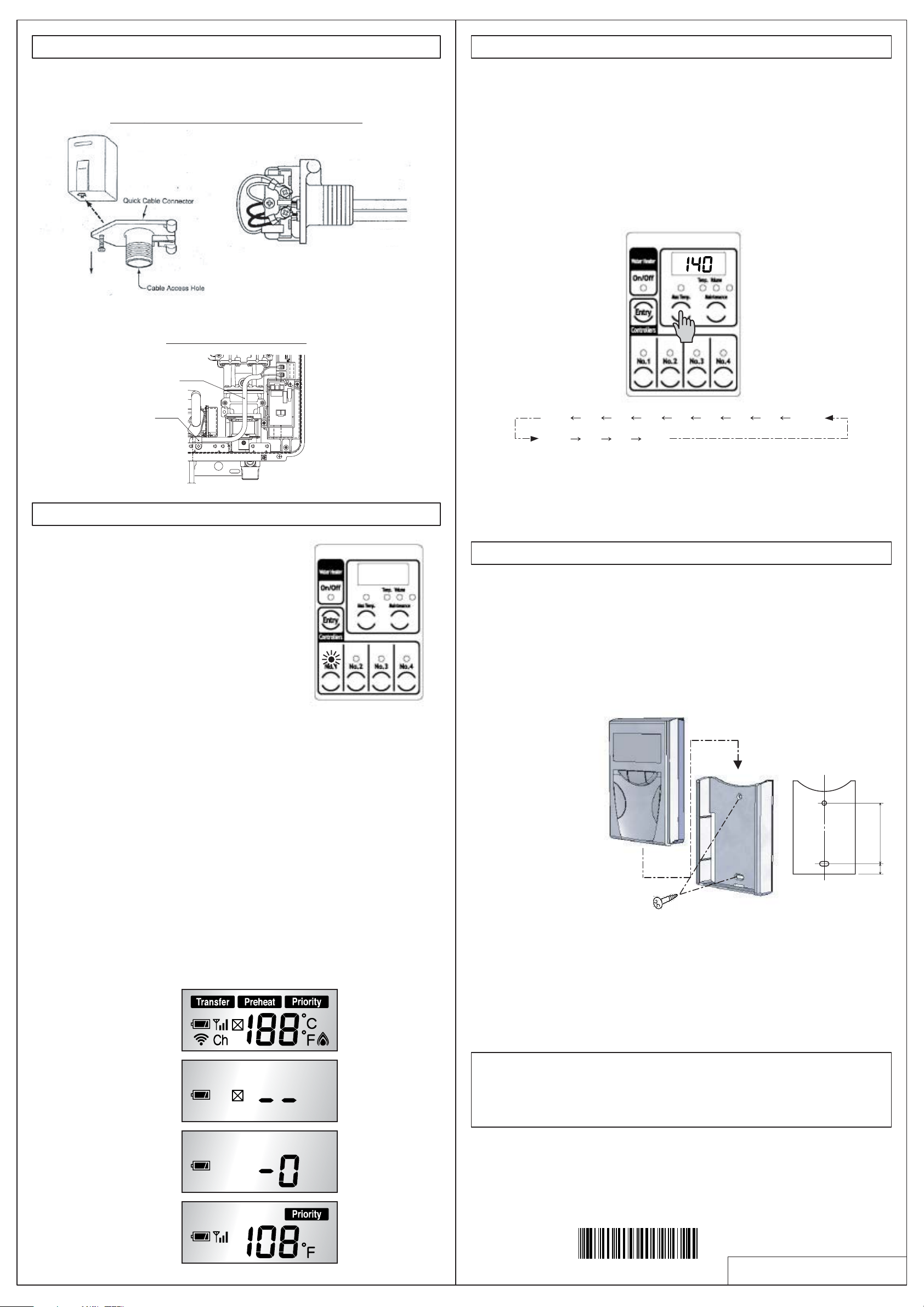
Install the Wireless Controller
Note: Before attaching the holder, confirm that the wireless controller is within range
with any intervening doors closed.
(1) Select a level surface on the wall.
(2) Install the holder using two screws. Use the anchors with the screws if installing on
a concrete wall or sheetrock. Do not over tighten. Do not tighten using a powered
screwdriver.
(3) Slide the remote control into the holder.
• Position wireless
controller
• Mark and drill holes
(ø1/8")
• If necessary place
anchors in (ø3/16")
• Position wireless controller
and screw in
4.33"(110)
0.61"(15.5)
screen A
screen B
screen C
screen D
(This device complies with Part 15 of FCC Rules and RSS-Gen of IC Rules.)
Operation is subject to the following two conditions: (1) this device may not cause
interference, and (2) this device must accept any interference, including
interference that may cause undesired operation of this device.
Warning
Changes or modifications not expressly approved by the party responsible for
compliance could void the user’s authority to operate the equipment.
070 00012 55124 1
U284-0180(00)
 Loading...