

Page 1
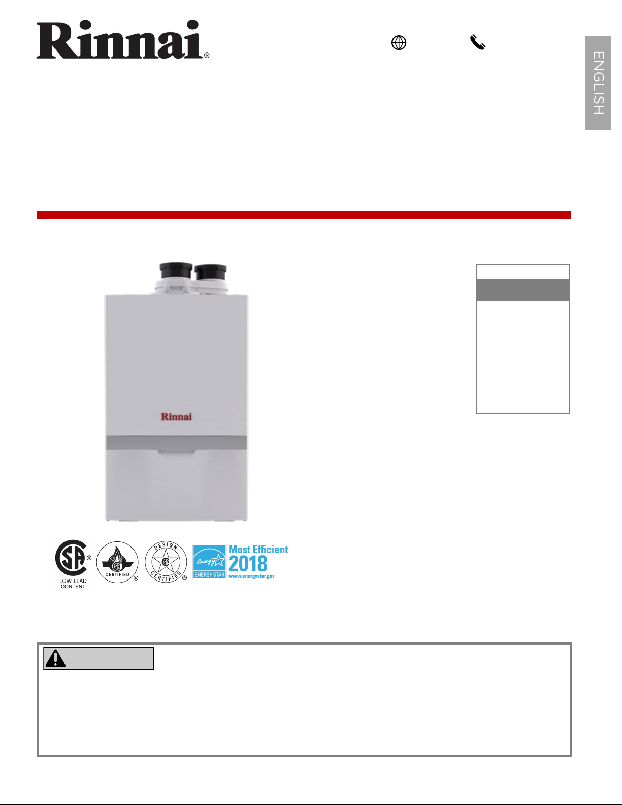
Rinnai M-Series Condensing Combi Boiler Installaon and Operaon Manual
If the informaon in these instrucons is not followed exactly, a re or explosion
may result causing property damage, personal injury, or death.
• Do not store or use gasoline or other ammable vapors and liquids in the vicinity of this or any other appliance.
• WHAT TO DO IF YOU SMELL GAS
− Do not try to light any appliance.
− Do not touch any electrical switch; do not use any phone in your building.
− Immediately call your gas supplier from a neighbor’s phone. Follow the gas supplier’s instrucons.
− If you cannot reach your gas supplier, call the re department.
• Installaon and service must be performed by a qualied installer, service agency or the gas supplier.
INSTALLATION AND OPERATION MANUAL
M-Series Condensing Boiler
Wall-Mounted, Gas-Fired Combi Boiler
8U513700/06.18 Changes Reserved
Central Heang and Domesc Hot Water
1-800-621-9419
rinnai.us
WARNING
Cered to ANSI Z21.13 and CSA 4.9
WARNING
MODELS
M060C
M090C
M120C
M160C
Page 2

2 Rinnai M-Series Condensing Combi Boiler Installaon and Operaon Manual
Contents
READ AND SAVE THESE INSTRUCTIONS
1 Welcome ........................................................ 3
2 Safety ............................................................. 4
Safety Symbols .................................................... 4
Safety Precauons ............................................... 5
3 About the Boiler ............................................. 6
Components ........................................................ 6
Specicaons ...................................................... 7
Dimensions .......................................................... 8
Accessories .......................................................... 9
How to Remove the Front Panel ...................... 10
4 Installaon ........................................................ 11
Installaon Overview ........................................ 11
Installaon Guidelines ....................................... 12
Unpack the Boiler .............................................. 13
Choose an Installaon Locaon ........................ 14
Mount the Boiler to the Wall ............................ 16
5 Venng ......................................................... 17
Venng Guidelines ............................................ 17
Venng Installaon Sequence .......................... 18
Terminaon Consideraons .............................. 18
Venng Opons................................................. 19
6 System Piping .............................................. 38
Piping for Central Heang Systems ................... 38
Piping for DHW Systems.................................... 42
Connect the Condensate Drain Line ................. 44
Connect the Pressure Relief Valves................... 46
7 Gas Supply .................................................... 47
Connect the Gas Supply .................................... 47
Gas Operang Instrucons ............................... 48
Gas Pipe Sizing Reference Tables ...................... 49
Test the Ignion Safety Shut O Device ........... 51
8 Power Supply ................................................ 52
Guidelines ......................................................... 52
Electrical Connecons ....................................... 53
Post-Power Supply Connecon Checklist ......... 53
9 Commissioning ............................................. 54
Safety Precauons ............................................ 54
Instrucons ....................................................... 54
10 Post-Installaon Checklist ............................. 57
11 Operaon ..................................................... 59
Start-Up Informaon ........................................ 59
Control Panel .................................................... 60
Boiler Display .................................................... 61
Basic Operaon Sengs ................................... 62
12 Maintenance ................................................. 74
Boiler Maintenance .......................................... 74
Flushing the Plumbing System for Central
Heang Systems ............................................... 75
13 Appendices ................................................... 77
Approved Cleaners, Inhibitors and Anfreezes 77
Boiler Parts ........................................................ 78
System Applicaon Examples ........................... 86
Gas Conversion ................................................. 92
Wiring Diagram ................................................. 96
Ladder Diagram ................................................. 97
Pressure Drop and Water Flow Curve ............. 98
Resistance/Temperature Table for Sensors ..... 99
Remove a Boiler From a Common Vent
System ............................................................ 100
Massachuses State Gas Regulaons ............ 101
Warranty ......................................................... 102
Page 3
Rinnai M-Series Condensing Combi Boiler Installaon and Operaon Manual 3
For an approved list of system cleaners,
inhibitors, and anfreezes, reference the
following secon in the Appendix: Approved
Cleaners, Inhibitors and Anfreezes
If You Need Service
Contact your local dealer/distributor or call Rinnai
Customer Care at 1-800-621-9419 Monday to Friday
between 8 AM to 8 PM ET. Please have your full serial
number or model number available for product- or
service-related issues.
Thank you for purchasing a Rinnai M-Series Condensing Boiler. Before installing and operang this boiler, be sure to
read these instrucons completely and carefully to familiarize yourself with the boiler’s features and funconality.
To The Consumer
• You must read the enre manual to properly
operate the boiler and to have regular
maintenance performed.
• Keep this manual for future reference.
• As when using any appliance generang heat,
there are certain safety precauons you should
follow. See the Safety Precauons secon in
this manual for detailed safety precauons.
• Be sure your boiler is installed by a licensed
installer.
• If installing in the state of Massachuses, you
must read the Massachuses State Gas
Regulaons secon in this manual.
To The Installer
• A trained and qualied professional must
install the boiler, inspect it, and leak test it
before use. The warranty will be voided due to
any improper installaon.
• The trained and qualied professional should
have skills such as:
− Gas line sizing
− Connecng gas lines, water lines, valves,
and electricity
− Knowledge of applicable naonal, state,
and local codes
− Installing venng through a wall or roof
− Training in installaon of condensing
boilers. Training on Rinnai M-Series
Condensing Boilers is accessible at
www.trainingevents.rinnai.us.
• Read all instrucons in this manual before
installing the boiler. The boiler must be
installed according to the exact instrucons in
this manual.
• Proper installaon is the responsibility of the
installer.
• When installaon is complete, leave this
manual with the boiler or give the manual
directly to the consumer.
Welcome
1
Acronyms and Abbreviaons
Following is a list of acronyms and abbreviaons used in this
manual:
ANSI American Naonal Standards Instute
BTU Brish Thermal Unit
CH Central Heang
Combi Combinaon (meaning the combinaon of
Central Heang and Domesc Hot Water)
DHW Domesc Hot Water
GPM Gallons per minute
LP Liquid Propane
NG Natural Gas
O2 Oxygen
PP Polypropylene
PSI Pounds per square inch
W.C. Inches water column
For Your Records
Dealer Name:
Dealer Phone #:
Purchase Date:
Serial #:
Located on boom le side of unit
QUICK REFERENCE
Page 4
4 Rinnai M-Series Condensing Combi Boiler Installaon and Operaon Manual
• If the informaon in these instrucons is not followed exactly, a re or explosion may result causing property
damage, personal injury, or death.
• Do not store or use gasoline or other ammable vapors and liquids in the vicinity of this or any other appliance.
• WHAT TO DO IF YOU SMELL GAS:
− Do not try to light any appliance.
− Do not touch any electrical switch; do not use any phone in your building.
− Immediately call your gas supplier from a neighbor’s phone. Follow the gas supplier’s instrucons.
− If you cannot reach your gas supplier, call the re department.
• Installaon and service must be performed by a qualied installer, service agency or the gas supplier.
• The warning signs in this manual are here to prevent injury to you and others. Please follow them explicitly.
WARNING
Indicates an imminently hazardous
situaon which, if not avoided, will
result in personal injury or death.
Indicates a potenally hazardous
situaon which, if not avoided,
could result in personal injury or
death.
Indicates a potenally hazardous
situaon which, if not avoided,
could result in minor or moderate injury. It may also be used to
alert against unsafe pracces.
Safety alert symbol. Alerts you to potenal
hazards that can kill or hurt you and others.
DANGER
CAUTION
WARNING
This manual contains the following important safety symbols. Always read and obey all safety messages.
Safety Symbols
Safety
2
Topics in this secon
• Safety Symbols
• Safety Precauons
Page 5
Rinnai M-Series Condensing Combi Boiler Installaon and Operaon Manual 5
The following precauons apply to the installer and consumer. Read and follow all instrucons in this secon.
• Do not use an extension cord or adapter plug with this
appliance.
• Any alteraon to the appliance or its controls can be
dangerous and will void the warranty.
• Proper venng is required for the safe operaon of this
appliance.
• Flammable liquids such as cleaning solvents, aerosols,
paint thinners, adhesives, gasoline and propane must
be handled and stored with extreme care. These
ammable liquids emit ammable vapors and when
exposed to an ignion source can result in a re hazard
or explosion. Flammable liquids should not be used or
stored in the vicinity of this or any other gas appliance.
• DO NOT operate the boiler without the front panel
installed. The front panel should only be removed for
service/maintenance or replacing internal components.
• BURN HAZARD. Hot exhaust and vent may cause
serious burns. Keep away from the boiler. Keep small
children and animals away from the boiler.
• Heang supply, return and domesc hot water outlet
pipes leaving the boiler can be hot to touch.
• Do not store or use gasoline or other ammable vapors
and liquids in the vicinity of this or any other appliance.
• Install the vent system per local and naonal codes.
• Do not install this boiler above 10,200 (3,109 m).
• Do not obstruct combuson air to the boiler.
• Failure to properly vent this appliance can result in
death, personal injury and/or property damage.
• Rinnai recommends that every home have a carbon
monoxide (CO) alarm in the hallway near bedrooms in
each sleeping area. Check baeries monthly and
replace them annually.
• California law requires the following Proposion 65
warning to be provided:
WARNING
This product can expose you to chemicals including
Nickel compounds, Lead and Lead compounds which are
known to the State of California to cause cancer, birth
defects or other reproducve harm. For more
informaon, visit www.P65Warnings.ca.gov.
Safety Precauons
• Before operang, smell all around the appliance
area for gas. Be sure to smell next to the oor
because some gas is heavier than air and will sele
on the oor.
• Keep the area around the appliance clear and free
from combusble materials, gasoline, and other
ammable vapors and liquids.
• Combusble construcon refers to adjacent walls
and ceiling and should not be confused with
combusble or ammable products and materials.
Combusble and/or ammable products and
materials should never be stored in the vicinity of
this or any gas appliance.
• Always check the water temperature before
entering a shower or bath.
• To protect yourself from harm, before performing
maintenance:
− Turn o the electrical power supply by
unplugging the power cord or by turning o the
electricity at the circuit breaker. (The boiler
controller does not control the electrical
power.)
− Turn o the gas at the gas control, usually
located immediately below the boiler.
− Turn o the incoming water supply. This can be
done at the isolaon valve immediately below
the boiler for the domesc hot water or by
turning o the water supply to the building for
the central heang system.
− Use only your hand to turn the manual gas
control valve. Never use tools. If the manual
gas control valve will not turn by hand, do not
try to repair it; call a trained and qualied
professional. Force or aempted repair may
result in a re or explosion.
• Do not use this appliance if any part has been under
water. Immediately call a licensed professional to
inspect the appliance and to replace any part of the
control system and any manual gas control valve
which has been under water.
• Do not use substute materials. Use only parts
cered for the appliance.
• Should overheang occur or the gas supply fail to
shut o, turn o the manual gas control valve to
the appliance.
• Only licensed professionals who are trained for
servicing Rinnai Condensing Boilers are permied
to adjust parameter sengs.
Page 6
6 Rinnai M-Series Condensing Combi Boiler Installaon and Operaon Manual
About the Boiler
3
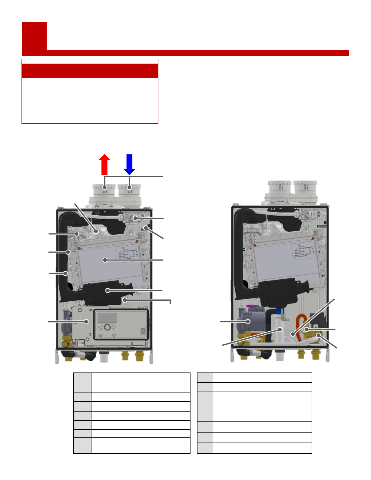
Components
❶
❷
❸
❹
❺
❻
❼
Located behind
#6 (Silencer)
❽
❾
❿
⓫
⓬
⓮
⓭
Topics in this secon
• Components
• Specicaons
• Dimensions
• Accessories
• How to Remove the Front Panel
1 iCon Heat Exchanger
2 Burner Hood with Burner Cassee
3 Fan with Integrated Venturi
4 Gas Valve
5 Ignion Unit
6 Silencer
7 Condensate Tray
8
Flue Gas Exhaust/Air Intake with
Measuring Points
9 Automac De-aerator
10 Control Panel
11 Pressure Sensor
12 Modulang Pump
13 Plate Heat Exchanger
14 Diverter Valve
15 Flow Sensor
16 Condensate Trap
⓯
⓰
Located behind
#6 (Silencer)
Exhaust
Intake
Page 7
Rinnai M-Series Condensing Combi Boiler Installaon and Operaon Manual 7
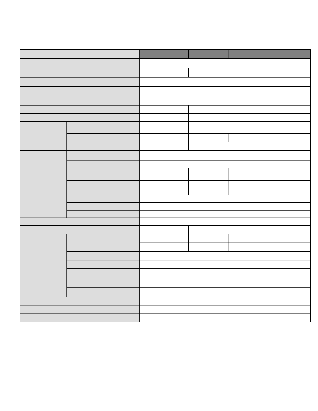
Model
M060C M090C M120C M160C
Dimensions - w, h, d 17 in. x 28 in. x 10 in. (439 mm x 699 mm x 264 mm)
Weight 77 lb (35 kg) 83.6 lb (38 kg)
Appliance Type Wall-Mounted, Gas-Fired Combi Boiler
Installaon Type Indoor
Ignion System Direct Electronic Ignion
Heat Exchanger Type iCon1 iCon2
Heat Exchanger Surface Area 7.3 sq 11.8 sq
Gas
Consumpon
(Btu/h)
Minimum
NG: 17,000
LP: 31,500
NG: 23,500
LP: 73,500
Maximum (Central Heang) 60,000 90,000 120,000 160,000
Maximum (DHW) 103,000 160,000
Temperature
Seng
Central Heang (Min - Max)
68° F - 185° F (20° C - 85° C)
DHW (Min - Max)
104° F - 149° F (40° C - 65° C)
Water Content
Central Heang
1 Gallon
3.8 Liters
1.4 Gallons
5.2 Liters
1.4 Gallons
5.2 Liters
1.4 Gallons 5.2
Liters
DHW
.05 Gallons
.2 Liters
.08 Gallons
.3 Liters
.08 Gallons
.3 Liters
.08 Gallons
.3 Liters
Water Supply
Pressure
Central Heang
Minimum: 19 PSI Maximum: 45 PSI
DHW
150 PSI (maximum)
Pressure Relief Valve
30 PSI
Pump Model UPER 15-78
Sound Level 46 dB 54 dB
Electrical Data
Normal Central Heang
155 W 177 W 164 W 191 W
DHW
185 W 191 W 191 W 191 W
Standby 3.5 W
Max Current 1.97 Amps (maximum)
Fuse 5 Amps
Gas
Supply Pressure
Natural Gas 3.0 in. - 10.5 in. W.C.
Propane 8.0 in. - 13.5 in. W.C.
Electric Connecons AC 120 Volts, 60Hz.
Energy Star Qualied Recognized as the Most Ecient of ENERGY STAR 2018
Cercaons ANSI Z21.13, CSA 4.9
1
Minimum ow may vary slightly depending on the temperature seng and the inlet water temperature. Minimum acvaon ow is 0.4 GPM (1.5 L/min).
2
The maximum gas supply pressure must not exceed the value specied by the manufacturer.
Rinnai products are connually being updated and improved; therefore, specicaons are subject to change without prior noce.
DHW = Domesc Hot Water
Specicaons
Page 8
8 Rinnai M-Series Condensing Combi Boiler Installaon and Operaon Manual
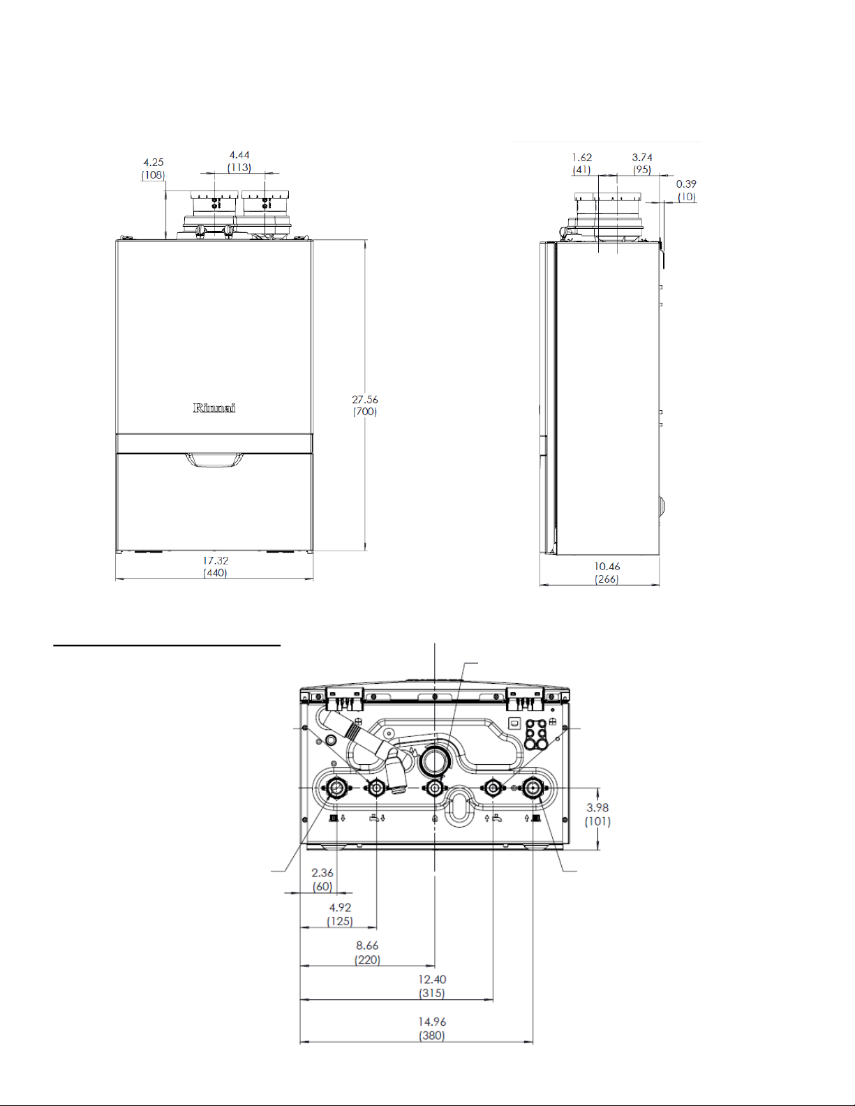
Side
Measurements: in. (mm)
Front
Supply Connecons
Gas
Central Heang
Return
Central Heang
Supply
Domesc Hot Water
Cold Inlet
Domesc Hot Water
Hot Outlet
Dimensions
Gas
Central Heang
Return
Domesc Hot Water
Cold Inlet
Page 9
Rinnai M-Series Condensing Combi Boiler Installaon and Operaon Manual 9
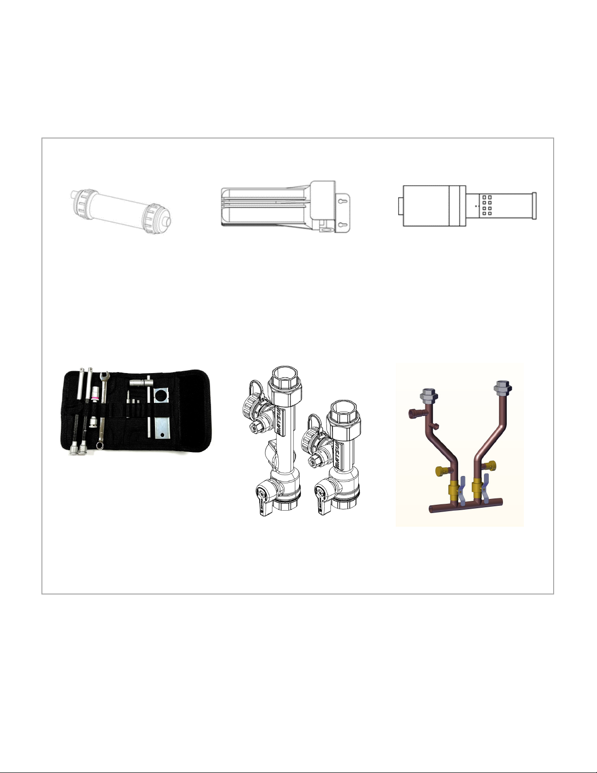
The following oponal accessories are available for the Rinnai M-Series Condensing Boiler.
For quesons, or to purchase an accessory, contact your local Rinnai dealer/distributor or call Rinnai Customer Care at
1-800-621-9419.
CONDENSATE NEUTRALIZER
Neutralizes the condensate
generated by the boiler.
SCALECUTTER
Filters and reduces the amount of
scale entering the boiler allowing
for greater boiler longevity.
SCALECUTTER REFILL CARTRIDGE
Rell cartridge for the ScaleCuer
lter assembly.
ISOLATION VALVE KIT
For quick isolaon of the
boiler DHW connecons.
BOILER TOOLKIT
Set of specic tools recommended
for boiler service.
Accessories
CLOSELY SPACED TEE KIT
Page 10
10 Rinnai M-Series Condensing Combi Boiler Installaon and Operaon Manual
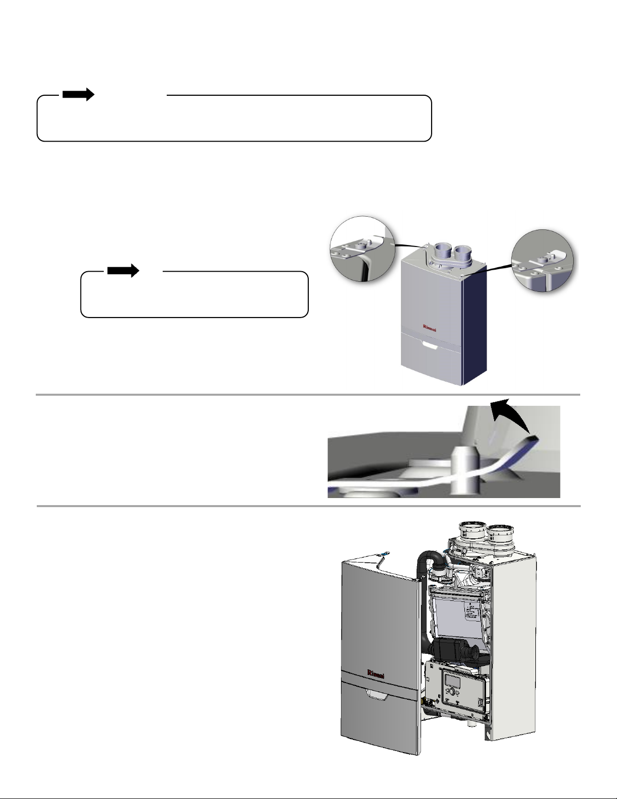
How to Remove the Front Panel
Using a Philips head screwdriver, remove
the 2 screws from the top of the boiler.
You Will Need:
• Philips head screwdriver
2
3
1
Li the tab slightly above the peg.
To remove, carefully li the panel up
and o to release it from the boiler.
IMPORTANT
Do not operate the boiler without the front panel installed. The front panel should
only be removed for service/maintenance or replacing internal components.
TIP
Be careful not to lose the screws. You’ll need
them when reinstalling the front cover.
Page 11
Rinnai M-Series Condensing Combi Boiler Installaon and Operaon Manual 11
THIS SECTION IS INTENDED FOR THE INSTALLER
Installer qualicaons: A trained and qualied professional must install the appliance, inspect it, and leak test the
boiler before use. The warranty will be voided due to any improper installaon. The trained and qualied professional
should have skills such as: Gas sizing; Connecng gas lines, water lines, valves, and electricity; Knowledge of applicable
naonal, state, and local codes; Installing venng through a wall or roof; and training in installaon of condensing
boilers. Training for Rinnai Condensing Boilers is accessible online at www.trainingevents.rinnai.us.
Installation
4
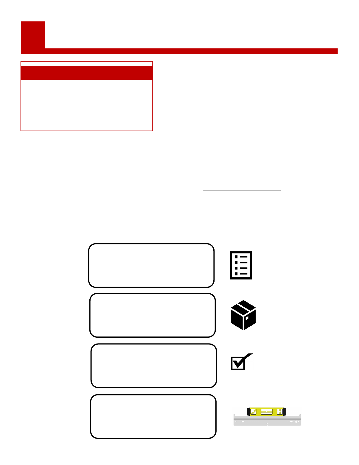
Installaon Overview
Below is an overview of the installaon process. Detailed informaon about each step is provided in the following
pages.
Topics in this secon
• Installaon Overview
• Installaon Guidelines
• Unpack the Boiler
• Choose an Installaon Locaon
• Mount the Boiler to the Wall
2
3
4
1
Read and Understand the
Installaon Guidelines
Unpack the Boiler and
Verify the Contents
Choose an Installaon
Locaon
Mount the Boiler
to the Wall
Consider water quality,
environment, and
clearances
Page 12

12 Rinnai M-Series Condensing Combi Boiler Installaon and Operaon Manual
• This boiler is cered for installaon in residenal
and commercial applicaons.
• This boiler is suitable for combinaon water heang
and central heang.
• The installaon must conform with local codes or, in
the absence of local codes, with the Naonal Fuel
Gas Code, ANSI Z223.1/NFPA 54, or the Natural Gas
and Propane Installaon Code, CSA B149.1. If
installed in a manufactured home, the installaon
must conform with the Manufactured Home
Construcon and Safety Standard, Title 24 CFR, Part
3280 and/or CAN/SCA Z240 MH Series, Mobile
Homes.
• The appliance, when installed, must be electrically
grounded in accordance with local codes or, in the
absence of local codes, with the Naonal Electrical
Code, ANSI/NFPA 70, or the Canadian Electrical
Code, CSA C22.1.
• The appliance and its main gas valve must be
disconnected from the gas supply piping system
during any pressure tesng of that system at test
pressures in excess of 1/2 psi (3.5 kPa) (13.84 in
W.C.). For system tesng at pressures less than or
equal to 1/2 psi (3.5 kPa) (13.84 in W.C.) the
appliance must be isolated from the gas supply
piping by closing its individual manual shuto valve.
• You must follow the installaon instrucons and
those in the Venng secon for adequate
combuson air and exhaust.
• If this boiler’s DHW system is connected to a closed
water supply system, such as one having a backow
preventer in the cold water supply line, means shall
be provided to control thermal expansion. Contact
the water supplier or local plumbing inspector on
how to control thermal expansion.
• Should overheang occur or the gas supply fail to
shut o, turn o the manual gas control valve to the
appliance.
• Combuson air must be free of chemicals, such as
chlorine or bleach, that produce fumes. These
fumes can damage components and reduce the life
of your appliance.
DO NOT install the boiler in an area where
water leakage of the unit or connecons will
result in damage to the area adjacent to the
appliance or to lower oors of the structure.
When such locaons cannot be avoided, it is
required that a suitable drain pan, adequately
drained, be installed under the boiler. The pan
must not restrict combuson air ow.
DO NOT install the boiler in an area with
negave air pressure.
DO NOT obstruct the ow of combuson and
venlaon air.
DO NOT use substute parts that are not
authorized for this appliance.
DO NOT install the boiler on carpeng.
DO NOT
Installaon Guidelines
Page 13

Rinnai M-Series Condensing Combi Boiler Installaon and Operaon Manual 13
Carefully unpack your boiler system and verify the
following contents are included.
If any items are damaged or missing, contact your local
dealer/distributor or call Rinnai Customer Care at 1-800621-9419. Do not aempt to use any item that appears
damaged.
Items included with boiler package:
• Rinnai Condensing Boiler
• Integrated Modulang Pump
• Wall Mounng Bracket
• Pressure Relief Valve (for Central Heang
Systems)
• Condensate Collector Kit
• Outdoor Reset Sensor
• 3 in. (80 mm) Polypropylene to 3" PVC
Adapter (Qty 2)
• 3 in. PVC to 2 in. PVC or 2 in. (60 mm)
Polypropylene adapter (Qty 2)
• 3 in. X 5 in. Concentric Vent Adapter
• Vent top with integrated 3 in. (80mm)
Polypropylene Adapters
• NPT Adapters:
− 1 in. (25 mm) for Central Heang
Systems (Qty 2)
− 3/4 in. (19 mm) (Qty 3 total)
• (Qty 2) for Domesc Hot Water Systems
• (Qty 1) for Gas Supply connecon
• Liquid Propane Field Conversion Kit
• Installaon and Operaon Manual (this manual)
• User Manual
• ISCL (Installaon, Service, and Commissioning Log)
To avoid danger of suocaon, keep plasc bags
away from babies, small children and pets. Do not
use these bags in cribs, beds, carriages, or playpens.
The bags are not a toy.
WARNING
Gather the recommended tools and parts before
starng installaon.
Tools Needed
• Standard tools for central heang, gas ng
and plumbing.
• Digital manometer capable of reading both
posive and negave pressure
• Combuson analyzer (intended for use with
condensing boilers)
• Digital mulmeter capable of reading
microamps
• pH digital meter or test strips
• Metric Allen wrenches (use metric only)
• Metric Socket wrenches (use metric only)
• For wall mounng bracket installaon:
− Level
− Screws (use appropriate screws for type
of wall construcon)
Other Items You May Need
• Hand truck with fastening belt
• Boiler toolkit (oponal accessory for boiler
service. See the Accessories secon for more
informaon)
Items Included What You’ll Need
Unpack the Boiler
Page 14
14 Rinnai M-Series Condensing Combi Boiler Installaon and Operaon Manual
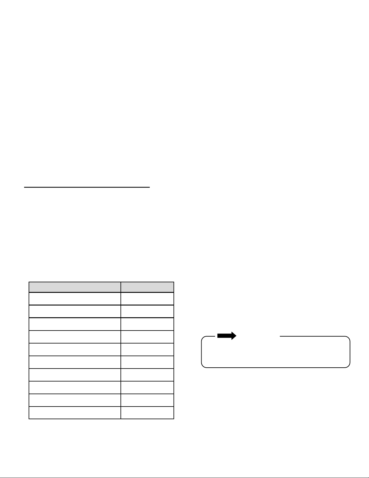
Contaminant Maximum Level
Total Hardness Up to 200 mg/L
Aluminum * Up to 0.2 mg/L
Chlorides * Up to 250 mg/L
Copper * Up to 1.0 mg/L
Dissolved Carbon Dioxide (CO2) Up to 15.0 mg/L
Iron * Up to 0.3 mg/L
Manganese * Up to 0.05 mg/L
pH * 6.5 to 8.5
TDS (Total Dissolved Solids) * Up to 500 mg/L
Zinc * Up to mg/L
Consideraon of care for your boiler should include
evaluaon of water quality.
• The water must be potable, free of corrosive
chemicals, sand, dirt, or other contaminants.
• It is up to the installer to ensure the water does
not contain corrosive chemicals or elements that
can aect or damage the boiler.
• Water that contains chemicals exceeding the levels
below can damage the boiler.
* Source: Part 143 Naonal Secondary Drinking
Water Regulaons
When choosing an installaon locaon, you must
ensure that clearances will be met and that the vent
length will be within required limits. Consider the
installaon environment, water quality, and need for
freeze protecon. Requirements for the gas line, water
lines, electrical connecon, and condensate disposal
can be found in their respecve installaon secons in
this manual.
This secon provides informaon on the importance of
water quality to the Rinnai Condensing Boiler. The
informaon is intended to serve as general guidelines
only and is not a complete list of water quality
guidelines.
• Unsuitable heang system water can cause the
formaon of scale or sludge, which aects system
eciency. It can also cause corrosion and reduce
life of the heat exchanger.
• Never use water that has been treated by a reverse
osmosis, deionized, or dislled water to soen the
water to ll the heang system.
• For DHW systems, if you install the boiler in an
area that is known to have hard water or that
causes scale build-up, the water must be treated
and may require a more frequent ushing
schedule. Scale build-up is caused by hard water
and can be accelerated if the boiler is set at a high
temperature. Rinnai oers Southeastern
Filtraon’s “ScaleCuer Water Condioning
System” that oers superior lime scale prevenon
and corrosion control by feeding a blend of control
compounds into the cold water supply.
• Do not use inhibitors or other addives unless
approved by Rinnai for that purpose.
• When using oxygen-permeable pipes for in-oor
heang systems, you must separate the system
from the boiler using plate heat exchangers.
• Thoroughly ush the system prior to lling. While
ushing, isolate the boiler.
• Do not introduce any system cleaner into the boiler
loop. Flush the system thoroughly to remove all
system cleaner before lling the boiler with water.
• When freeze protecon of the heang system is
desired, only use Rinnai-approved anfreezes. The
allowed maximum concentraon is 50%.
• Reference secon Approved Cleaners, Inhibitors
and Anfreezes in the Appendix for an approved
list of system cleaners, inhibitors, and anfreezes.
Choose an Installaon
Locaon
Water Quality Guidelines
IMPORTANT
Replacement of components due to water
quality damage is not covered by the warranty.
Page 15
Rinnai M-Series Condensing Combi Boiler Installaon and Operaon Manual 15
Use this checklist to ensure you have selected the correct locaon for the boiler.
Air surrounding the boiler, venng, and vent terminaon(s) is used for combuson and must be free of any compounds
that cause corrosion of internal components. These include corrosive compounds that are found in aerosol sprays,
detergents, bleaches, cleaning solvents, oil based paints/varnishes, and refrigerants. The air in beauty shops, dry
cleaning stores, photo processing labs, and storage areas for pool supplies oen contains these compounds. The boiler,
venng, and vent terminaon(s) should not be installed in any areas where the air may contain these corrosive
compounds.
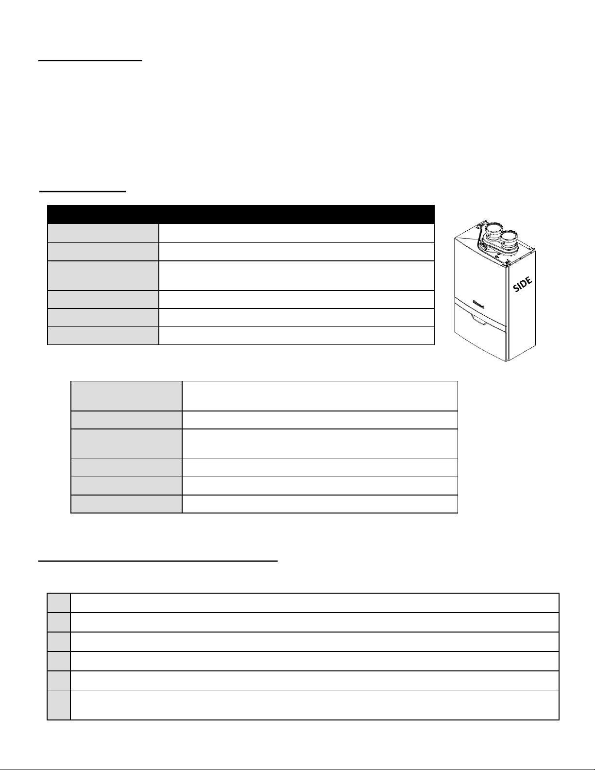
BOTTOM
TOP
FRONT
Locaon Clearance
Top 2 in. (51 mm) 0 in. from vent components
Boom (Ground) 12 in. (305 mm)
Front 6 in. (152 mm)
Clearance for servicing is 24 in. (610 mm) in front of boiler
Back 0 in.
Sides (Le and Right) 2 in. (51 mm)
Vent 0 in.
Environment
Clearances
Installaon Locaon Checklist
□
The boiler is not exposed to corrosive compounds in the air.
□
The boiler locaon complies with the required clearances.
□
The planned combuson air and exhaust terminaon locaons meet the required clearances.
□
The water supply does not contain chemicals or exceed total hardness that will damage the heat exchanger.
□
A standard 3 prong 120 VAC, 60 Hz properly grounded wall outlet or other 120 VAC, 60 Hz source is available.
□
The installaon must conform with local codes or, in the absence of local codes, with the Naonal Fuel Gas
Code, ANSI Z223.1/NFPA 54, or the Natural Gas and Propane Installaon Code, CSA B149.1.
Closet Installaon Clearances
Top 6 in. (152 mm)
0 in. from vent components
Boom (Ground) 12 in. (305 mm)
Front 6 in. (152 mm)
Clearance for servicing is 24 in. (610 mm) in front of boiler
Back 0 in.
Sides (Le and Right) 2 in. (51 mm)
Vent 0 in.
Page 16
16 Rinnai M-Series Condensing Combi Boiler Installaon and Operaon Manual
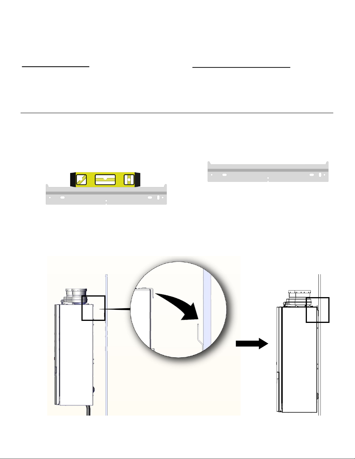
• Level
• Screws for boiler and mounng bracket
installaon (use appropriate screws for type of
wall construcon)
Hold the wall mounng bracket up against
the wall and use a level to make sure the
bracket is even.
Proper operaon requires the boiler to be
level.
Insert the boiler top bracket into the wall mounng bracket.
Make sure the wall mounng bracket is sturdy and can hold the weight of the boiler before you fully let go.
Wall Mounng Bracket
Level
Use the appropriate screws for the wall
construcon to secure the mounng bracket
to the wall (use any of the screw holes in the
mounng bracket).
Mount the Boiler to the Wall
You Will Need
Supplied by Installer
• Rinnai Condensing Boiler
• Wall Mounng Bracket
2
3
1
Insert the boiler top bracket into the wall mounng bracket
Assembled view
Page 17
Rinnai M-Series Condensing Combi Boiler Installaon and Operaon Manual 17
• M-Series boilers can be installed as direct vent or
non-direct vent applicaons.
• When installed as Direct Vent, refer to the
following secon for a complete list of approved
vent manufacturers and products: Venng Opons
→ Direct Vent: Approved Vent Manufacturers and
Products.
• When installed as Non-Direct Vent (Room Air), the
vent must be Category IV and of a type listed by a
naonal recognized tesng agency.
• Exhaust must be directly vented to the outside.
Combuson air can be provided from outside
(Direct Vent) or from room air (Non-Direct Vent).
• If using room air (non-direct vent) for combuson,
ensure the required volume of indoor air is
available according to the Naonal Fuel Gas Code,
ANSI Z223.1/NFPA 54.
• Avoid dips or sags in horizontal vent runs by
installing supports per the vent manufacturer’s
instrucons.
• Support horizontal vent runs every 4 (1.2 m) and
all vercal vent runs every 6 (1.83 m) or as per
vent manufacturer’s instrucons or local code
requirements.
• Venng should be as direct as possible with a
minimum number of pipe ngs.
• For manufactured vent systems, vent connecons
must be rmly pressed together so that the
connecons form an air ght seal. Follow the
venng manufacturer’s instrucons.
• Refer to the Schedule 40 PVC/CPVC manufacturer
for appropriate ngs, solvents or joining
methods.
WARNING
DO NOT use cellular core PVC/CPVC.
DO NOT use Radel, ABS, or galvanized material to
vent this appliance.
DO NOT cover non-metallic vent pipe and ngs
with thermal insulaon.
DO NOT combine vent components from
dierent manufacturers.
DO NOT reduce the vent diameter. Vent
diameter cannot be less than 2 in.
DO NOT connect the venng system with an
exisng vent or chimney.
DO NOT common vent with the vent pipe of any
other manufacturer’s boiler or appliance.
Venting
5
Venng Guidelines
Topics in this secon
• Venng Guidelines
• Venng Installaon Sequence
• Terminaon Consideraons
• Venng Opons
• If venng reassembly is needed, follow the steps
for installing the venng in the following
secons. Make certain that the vent piping and
seals are not damaged. Only use sealants,
primers, or glues that are approved for the vent
material in use.
• Refer to the instrucons of the vent system
manufacturer for component assembly
instrucons.
• If the vent system is to be enclosed, it is
suggested that the design of the enclosure shall
permit inspecon of the vent system. The design
of such enclosure shall be deemed acceptable by
the installer or the local inspector.
• Any issues resulng from improper vent
installaon will not be covered by warranty.
Page 18
18 Rinnai M-Series Condensing Combi Boiler Installaon and Operaon Manual
1. Install the boiler.
2. Determine the terminaon method—horizontal or
vercal, concentric, or twin pipes, etc.
3. Determine proper locaon for wall or roof
penetraon for each terminaon.
4. Install terminaon assembly as described in this
manual or in the vent manufacturer’s installaon
instrucons.
5. Install air and vent piping from boiler to
terminaon.
6. Slope horizontal exhaust run towards the boiler
1/4 in per foot. DO NOT slope combuson air pipe
towards boiler.
7. Install vent supports and brackets allowing for
movement from expansion, or as per vent
manufacturer’s instrucons or local code
requirements.
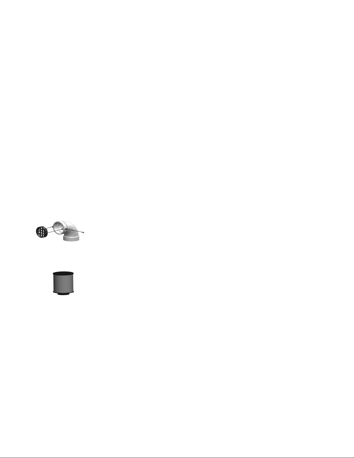
8. (Oponal step) Install vent screen or room air lter
(not included with purchase) on Schedule 40 PVC
combuson air and exhaust terminaon elbows as
illustrated below.
Check to determine whether local codes supersede the
following clearances:
• Avoid terminaon locaons near a dryer vent.
• Avoid terminaon locaons near commercial
cooking exhaust.
• Avoid terminaon locaons near any air inlets.
• You must install a vent terminaon at least 12 in
above the ground or ancipated snow level.
Press air lter into the 3 in.
(76 mm) PVC intake air ng
on the boiler.
Vent Screen
Room Air Filter
• Press vent screen inside of
terminaon piece/elbow.
• Secure vent screen to the
elbow with screw.
Venng Installaon Sequence
Terminaon
Consideraons
The vent for this appliance shall not terminate:
• Over public walkways.
• Near sot vents or crawl space vents or other area
where condensate or vapor could create a nuisance
or hazard or cause property damage.
• Where condensate or vapor could cause damage or
could be detrimental to the operaon of regulators
pressure relief valves, or other equipment.
Listed below are important consideraons for locang
vent terminaon under a sot (venlated or unvenlated
or eave vent; or to a deck or porch):
• Do not install vent terminaon under a sot vent
such that exhaust can enter the sot vent.
• Install vent terminaon such that exhaust and rising
moisture will not collect under eaves. Discoloraon
to the exterior of the building could occur if
installed too close.
• Do not install the vent terminaon too close under
the sot where it could present recirculaon of
exhaust gases back into the combuson air part of
the terminaon.
The instrucons for the installaons of the venng system
shall specify that the horizontal porons of the venng
system shall be supported to prevent sagging; the
methods of and intervals for support shall be specied.
These instrucons shall also specify that the venng
system:
• For category I, II and IV boilers, have horizontal runs
sloping upwards not less than 1/4" per foot (21mm/
m) from the boiler to the vent terminal;
• For category III boilers, slope shall be as specied in
the boiler manufacturer's instrucons;
• For category II and IV boilers, be installed so as to
prevent accumulaon of condensate; and
• For category II and IV boilers, where necessary, have
means provided for drainage of condensate.
Page 19
Rinnai M-Series Condensing Combi Boiler Installaon and Operaon Manual 19
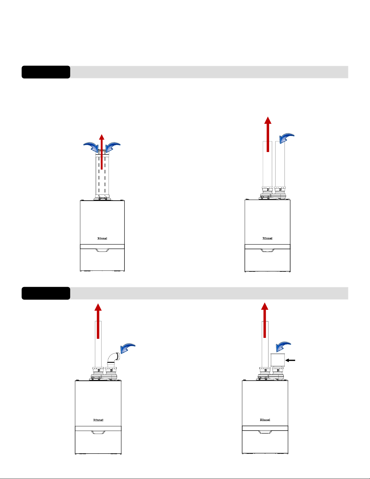
Two venng opons are available: Direct Vent and Room Air.
Concentric Pipe
Combuson air and exhaust vent directly through a single
concentric connecon. Hot exhaust exits through the interior
tube, while combuson air enters through the outer layer.
Exhaust
Twin Pipe
Combuson air and exhaust vent directly through
separate penetraons.
Direct Vent (Concentric and Twin Pipe)
Room air lter
Opon 1
Room Air
Opon 2
Combuson
air
Combuson
air
Exhaust
Combuson
air
Exhaust
Combuson
air
See Direct Vent secon for complete details.
See Room Air secon for complete details.
Exhaust
Combuson air
Venng Opons
Page 20
20 Rinnai M-Series Condensing Combi Boiler Installaon and Operaon Manual
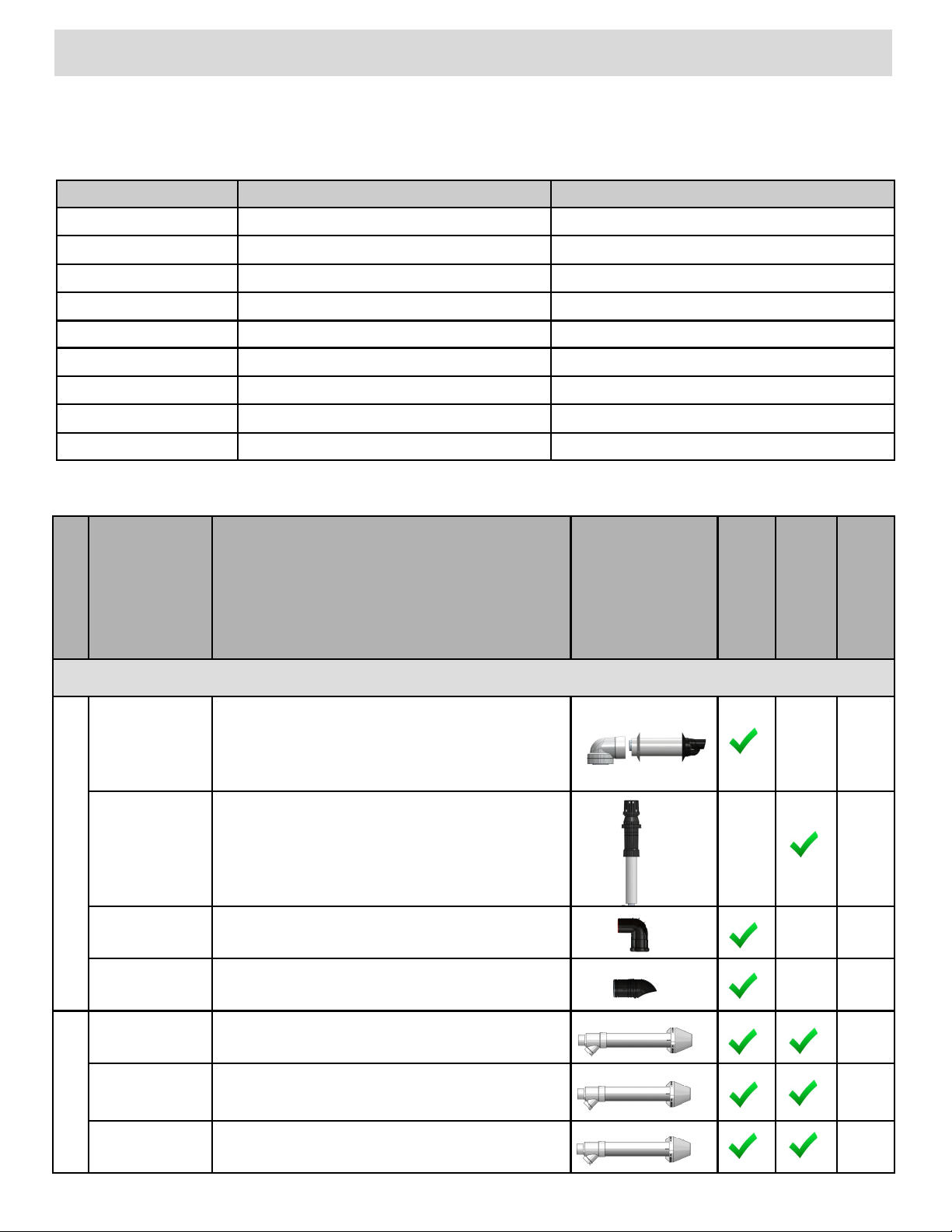
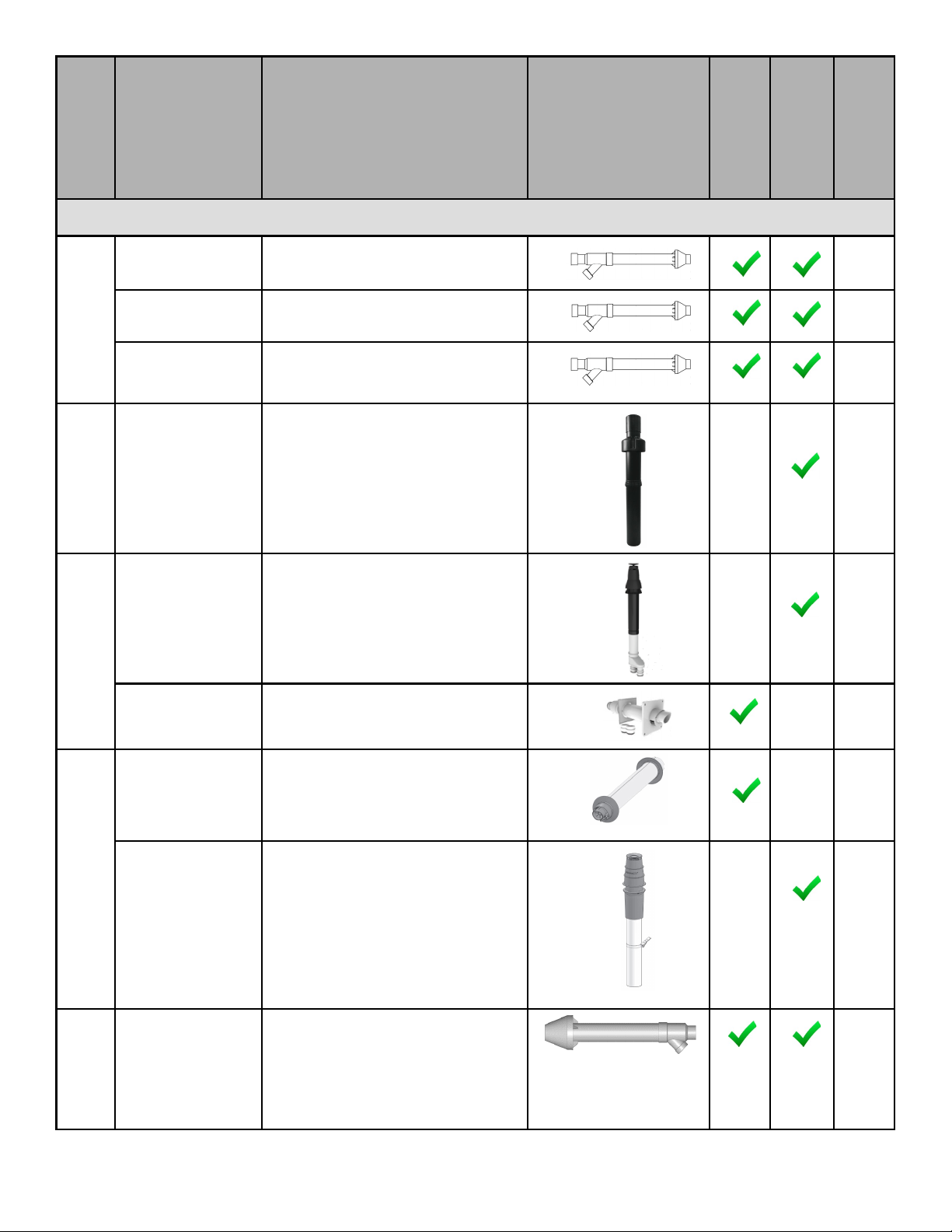
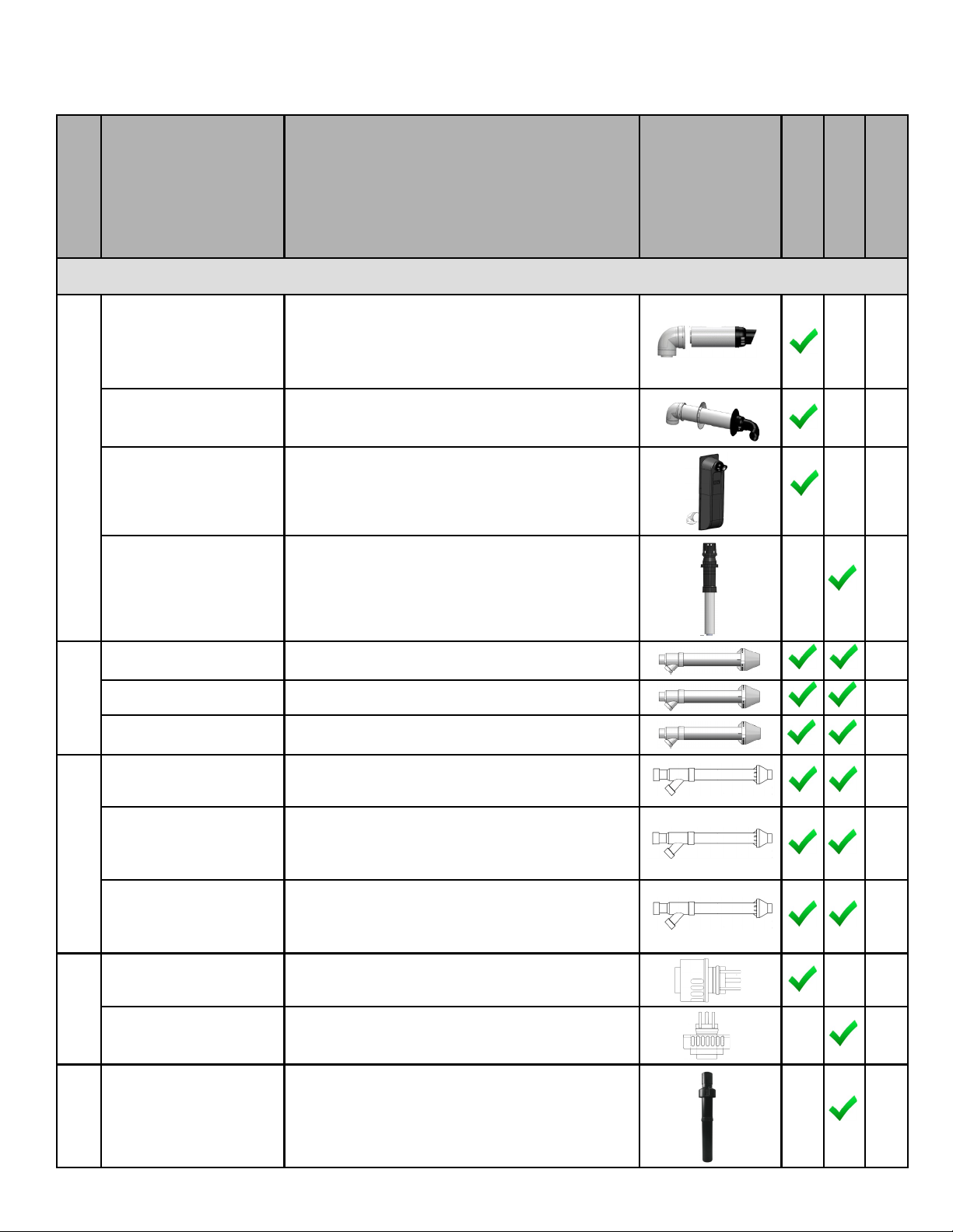
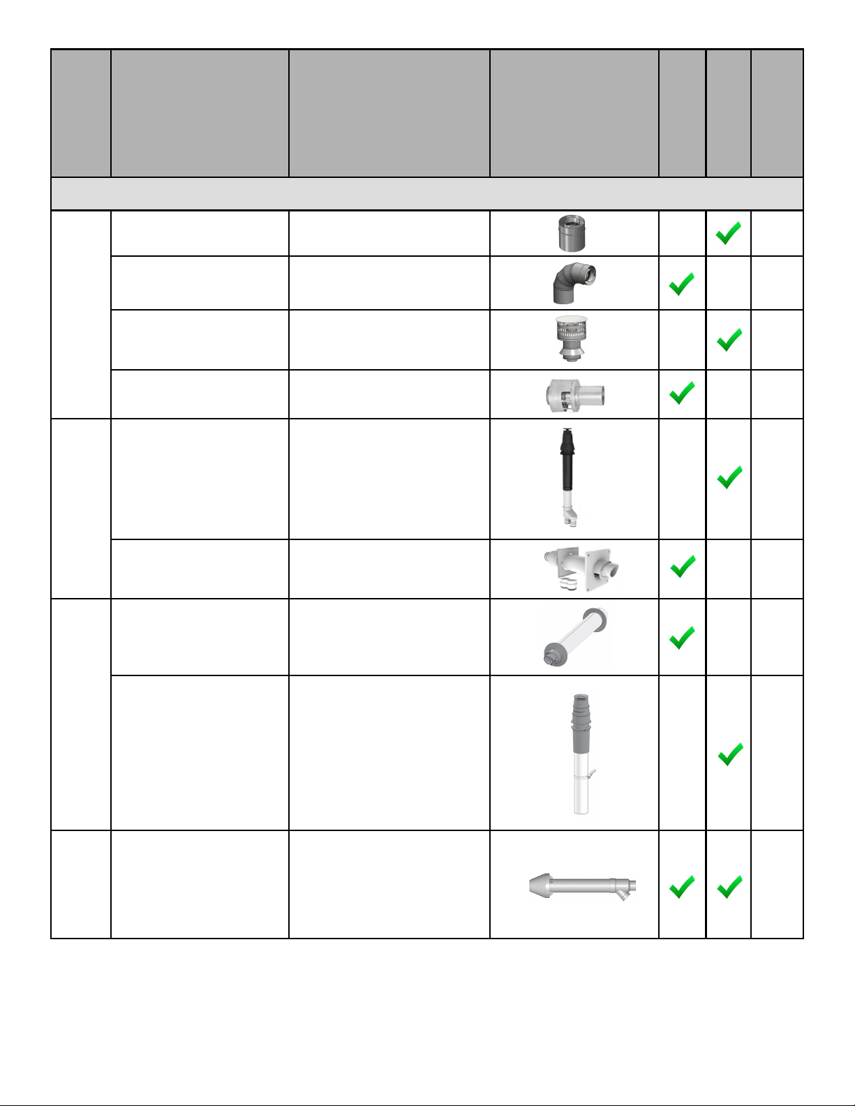
Following is a list of vent components and terminaons for Direct Vent installaons (concentric and twin pipe). Install
the correct venng for your model according to the venng manufacturer’s instrucons and the guidelines below. The
informaon below is correct at me of publicaon and is subject to change without noce. Contact the vent
manufacturer for quesons related to the vent system, products, part numbers and instrucons.
Manufacturer Phone Web Site
Ubbink 800-621-9419 www.rinnai.us
Centrotherm 877-434-3432 www.centrotherm.us.com
Heat-Fab 800-772-0739 www.heaab.com
Metal Fab 800-835-2830 www.metal-fabinc.com
IPEX U.S.: 800-463-9572 Canada: 866-473-9462 www.ipexamerica.com www.ipexinc.com
DuraVent 800-835-4429 www.duravent.com
Royal 800-232-5690 www.royalbuildingproducts.com
Ecco Manufacturing 877-955-4805 www.eccomfg.com
DiversiTech 800-995-2222 www.diversitech.com
Direct Vent: Approved Vent Manufacturers and Products
2 in./4 in. CONCENTRIC VENT TERMINATIONS
229011NPP
229012NPP
229013NPP
2/4 Condensing Horizontal Terminaon Kit 8.7 in.
2/4 Condensing Horizontal Terminaon Kit 12 in.
2/4 Condensing Horizontal Terminaon Kit 21 in.
5
224356NPP 2/4 Condensing Roof Discharge Terminaon
20 in. above roof
5
710202NPP 2/4 Condensing 90 Degree Diverter Nose
(Use with Wall Terminal)
5
710215NPP 2/4 Condensing 45 Degree Diverter Nose
(Use with Wall Terminal)
5
196005, 197040 FGV Concentric Vent Kit
(16 in. length)
20
196105, 197033 FGV Concentric Vent Kit
(28 in. length)
20
196125 FGV Concentric Vent Kit
(40 in. length)
20
UBBINK
IPEX
Manufacturer
Manufacturer
Part Number
Product
Descripon
Diagram
Horizontal
Vercal
Equivalent Length
()
2 in./4 in. CONCENTRIC VENT TERMINATIONS
Page 21
Rinnai M-Series Condensing Combi Boiler Installaon and Operaon Manual 21
2 in./4 in. CONCENTRIC VENT TERMINATIONS (Connued)
52CVKGVS6502 PVC Concentric Vent Kit 2 in. x 16 in.
20
52CVKGVS6502-28 PVC Concentric Vent Kit 2 in. x 28 in.
20
52CVKGVS6502-40 PVC Concentric Vent Kit 2 in. x 40 in.
20
ICRT2439 2 in. x 4 in. Concentric Roof
Terminaon
20
2PPS-VKL/VK-TCL 2 in. x 4 in. Vercal Terminaon
Cap Kit-Concentric
20
2PPS-HKL 2 in. x 4 in. Horizontal Terminaon
Kit-Concentric
20
190288 2 in. x 4 in. Concentric Horizontal
Terminaon
5
190295 2 in. x 4 in. Concentric Vercal
Terminaon
5
CVENT-2 2 in. x 4 in. Concentric Horizontal
Terminaon
20
ROYAL
CENTROTHERM
DURAVENT
Manufacturer
Manufacturer
Part Number
Product
Descripon
Diagram
Horizontal
Vercal
Equivalent Length
()
ECCO
DIVERSITECH
Page 22
22 Rinnai M-Series Condensing Combi Boiler Installaon and Operaon Manual
3 in./5 in. CONCENTRIC VENT TERMINATIONS
223174PP
223176PP
223177PP
3/5 Condensing Horizontal Terminaon Kit 8.7 in.
3/5 Condensing Horizontal Terminaon Kit 12 in.
3/5 Condensing Horizontal Terminaon Kit 21 in.
5
223186PP 3/5 Condensing Horizontal Diverter
Terminaon Kit 19 in.
16
224047PP 3/5 Condensing Raised Horizontal
Terminaon Kit
24
184162PP 3/5 Condensing Roof Discharge
Terminaon 20 in. above roof
5
196006, 197009 FGV Concentric Vent Kit 3 in. x 20 in.
20
196106, 197107 FGV Concentric Vent Kit 3 in. x 32 in.
20
196116, 197117 FGV Concentric Vent Kit 3 in. x 44 in.
20
52CVKGVS6503 (PVC)/
52CVKGVSF9003 (CPVC)
PVC/CPVC Concentric Vent Kit 3 in. x 20 in.
20
52CVKGVS6503-32
(PVC)/ 52CVKGVSF900332 (CPVC)
PVC/CPVC Concentric Vent Kit 3 in. x 32 in.
20
52CVKGVS6503-44
(PVC)/ 52CVKGVSF9003-
44 (CPVC)
PVC/CPVC Concentric Vent Kit 3 in. x 44 in.
20
SC03HT Horizontal Terminaon Adapter
20
SC03VT Vercal Terminaon Adapter
20
ICRT3539 3''/5'' Concentric Roof Terminaon PPs-UV
20
UBBINK
IPEX
ROYAL
CENTRO
-
THERM
HEAT
-FAB
Manufacturer
Manufacturer
Part Number
Product
Descripon
Diagram
Horizontal
Vercal
Equivalent Length
()
3 in./5 in. CONCENTRIC VENT TERMINATIONS
Page 23
Rinnai M-Series Condensing Combi Boiler Installaon and Operaon Manual 23
3 in./5 in. CONCENTRIC VENT TERMINATIONS (Connued)
3CGRLSV Vercal Adapter
1
3CGRLSH Horizontal Adapter
6
3CGRVT Vercal Terminaon
5
3CGRHT Horizontal Terminaon
16
3PPS-VKL/VK-TCL 3 in. x 5 in. Vercal
Terminaon Cap
Kit-Concentric
20
3PPS-HKL 3 in. x 5 in. Horizontal
Terminaon Kit-Concentric
20
190388 3 in. x 5 in. Concentric
Horizontal Terminaon
5
190395 3 in. x 5 in. Concentric Vercal
Terminaon
5
CVENT-3 3 in. x 5 in. Concentric
Horizontal Terminaon
20
METAL
-FAB
ECCO
Manufacturer
Manufacturer
Part Number
Product
Descripon
Diagram
Horizontal
Vercal
Equivalent Length
()
DURAVENT
DIVERSITECH
Page 24
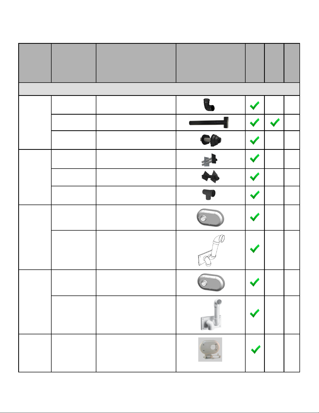
24 Rinnai M-Series Condensing Combi Boiler Installaon and Operaon Manual
2 in. TWIN PIPE TERMINATIONS
2 in. TWIN PIPE TERMINATIONS
ISELL0287UV 2 in. 87° Long PPS-UV
6
ISTT0220 2 in. Terminaon Tee
6
ISLPT0202 2 in. Low Prole Wall
Terminaon
5
2PPS-HTPL 2 in. Twin Pipe Terminaon
10
2PPS-HSTL 2 in. Single Horizontal
Terminaon
6
2PPS-TBL 2 in. Black UV Resistant Tee
5
196984 FGV PVC Low Prole
Terminaon Kit
5
081216 FGV PVC Wall Terminaon
Kit
16
52SWVKGVS6502 PVC Side Wall Vent Kits
5
52WTVKGVS6502 PVC Wall Vent Kits
16
HVENT-2 2 in. Low Prole Horizontal Vent
Kit
5
CENTROTHERM
DURAVENT
Manufacturer
Manufacturer
Part Number
Product
Descripon
Diagram
Horizontal
Vercal
Equivalent
Length ()
IPEX
ROYAL
DIVERSITECH
Page 25
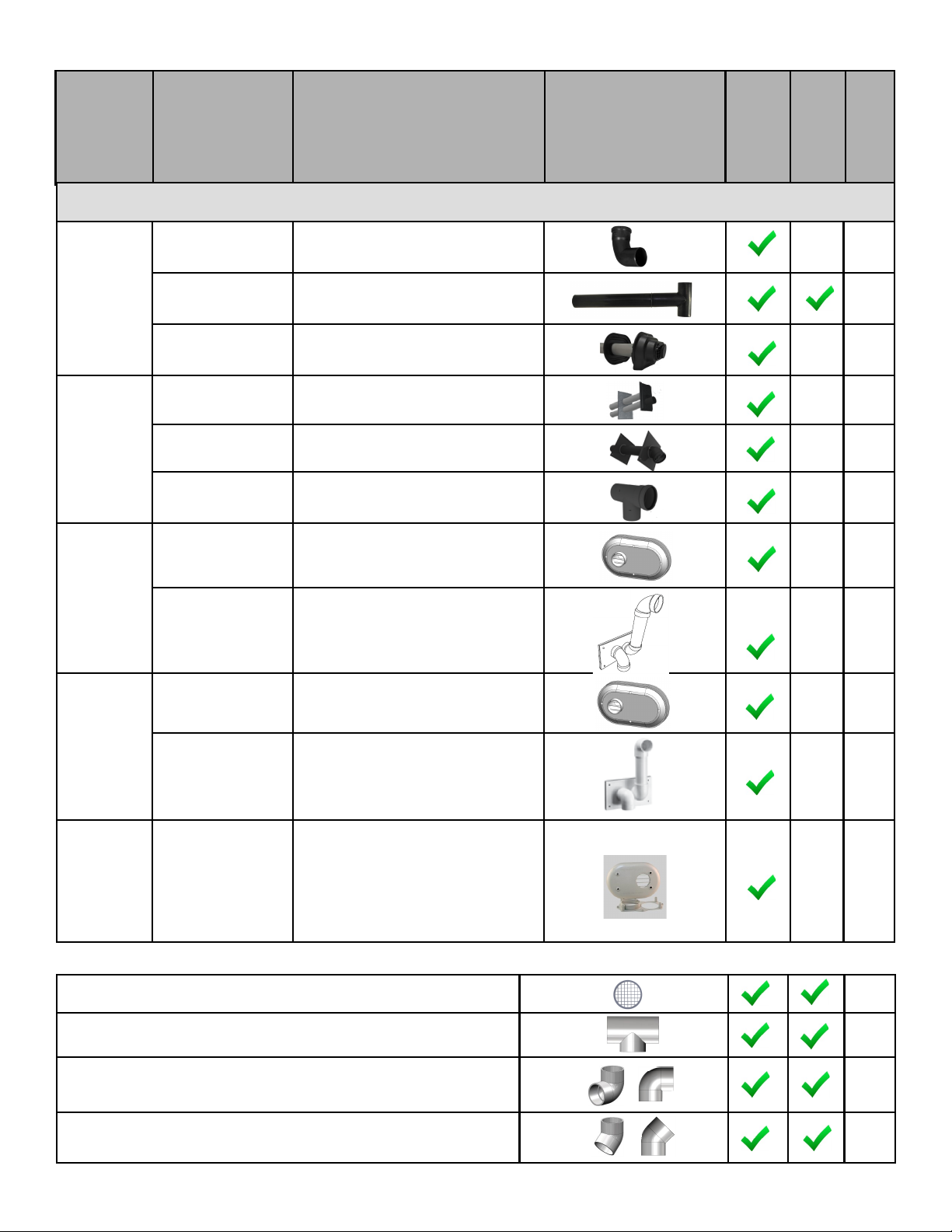
Rinnai M-Series Condensing Combi Boiler Installaon and Operaon Manual 25
3 in. TWIN PIPE TERMINATIONS
ISELL0387UV 3 in. 87° Long PPS-UV
6
ISTT0320 3 in. Terminaon Tee
6
ISLPT0303 3 in. Low Prole Wall Terminaon
5
3PPS-HTPL 3 in. Twin Pipe Terminaon
10
3PPS-HSTL 3 in. Single Horizontal Terminaon
5
3PPS-TBL 3 in. Black UV Resistant Tee
6
196985 FGV PVC Low Prole Terminaon
Kit
5
081219 FGV PVC Wall Terminaon Kit
16
52SWVKGVS6503 PVC Side Wall Vent Kits
5
52WTVKGVS6503 PVC Wall Vent Kits
16
HVENT-3 3 in. Low Prole Horizontal Vent
Kit
5
CENTROTHERM
DURAVENT
Manufacturer
Manufacturer
Part Number
Product
Descripon
Diagram
Horizontal
Vercal
Equivalent
Length ()
IPEX
ROYAL
3 in. TWIN PIPE TERMINATIONS
Air Filter Screen
N/A
Tee
5
90° Elbow
5
2.5 45° Elbow
DIVERSITECH
VARIOUS 2 in. OR 3 in. SCHEDULE 40 PVC/CPVC TERMINATIONS
Page 26
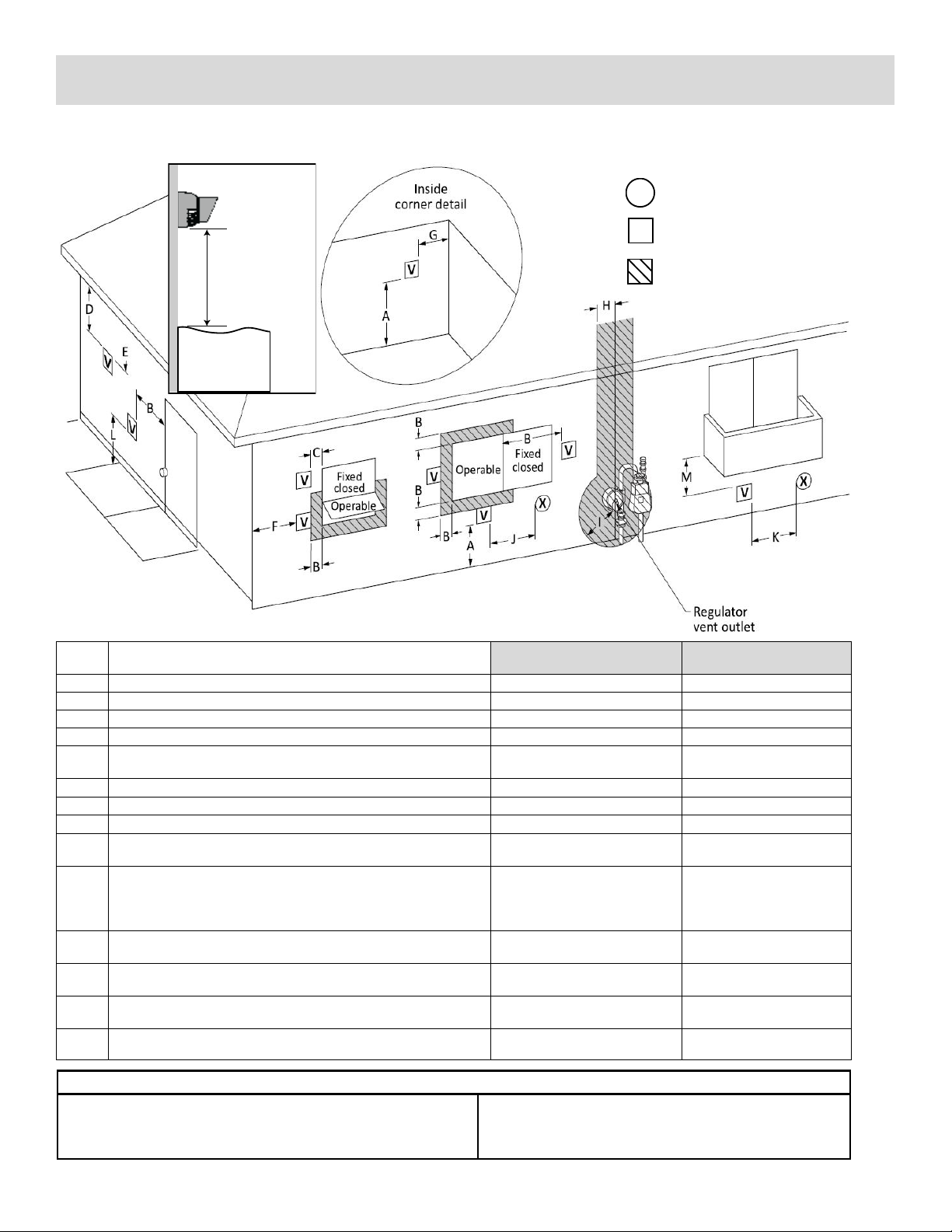
26 Rinnai M-Series Condensing Combi Boiler Installaon and Operaon Manual
Canadian Installaons
(CSA B149.1)
U.S. Installaons
(ANSI Z223.1 /NFPA 54)
Ref Descripon Direct Vent (Indoor Unit) Direct Vent (Indoor Unit)
A Clearance above grade, veranda, porch, deck, or balcony 12 in. (30 cm) 12 in. (30 cm)
B Clearance to window or door that may be opened 36 in. (91 cm) 12 in. (30 cm)
C Clearance to permanently closed window * *
D
Vercal clearance to venlated sot, located above the terminal within a
horizontal distance of 2 (61 cm) from the center line of the terminal
* *
E Clearance to unvenlated sot * *
F Clearance to outside corner * *
G Clearance to inside corner * *
H
Clearance to each side of center line extended above meter/regulator
assembly
* *
I Clearance to service regulator vent outlet
Above a regulator within 3
(91 cm) horizontally of the vercal
center line of the regulator vent
outlet to a maximum vercal
distance of 15 (4 m)
*
J
Clearance to non-mechanical air supply inlet to building or the
combuson air inlet to any other appliance
36 in. (91 cm) 12 in. (30 cm)
K Clearance to a mechanical air supply inlet 6 (1.83 m)
3 (91 cm) above if within
10 (3 m) horizontally
L
Clearance above paved sidewalk or paved driveway located on public
property
7 (2.13 m) [1] *
M Clearance under veranda, porch, deck, or balcony 12 in. (30 cm) [2] *
AIR SUPPLY INLET
VENT TERMINAL
AREA WHERE TERMINAL
IS NOT PERMITTTED
X
V
SNOW
TERMINATION
Clearance in
Ref. A also
applies to
anticipated
snow line
Clearance to opposite wall is 24 in. (60 cm).
[1] A vent shall not terminate directly above a sidewalk or paved driveway that
is located between two single family dwellings and serves both dwellings.
[2] Permied only if veranda, porch, deck, or balcony is fully open on a mini-
mum of two sides beneath the oor.
Clearances are in accordance with local installaon codes and the
requirements of the gas supplier.
The informaon below applies to Concentric and Twin Pipe.
Direct Vent: Terminaon Clearances
Page 27
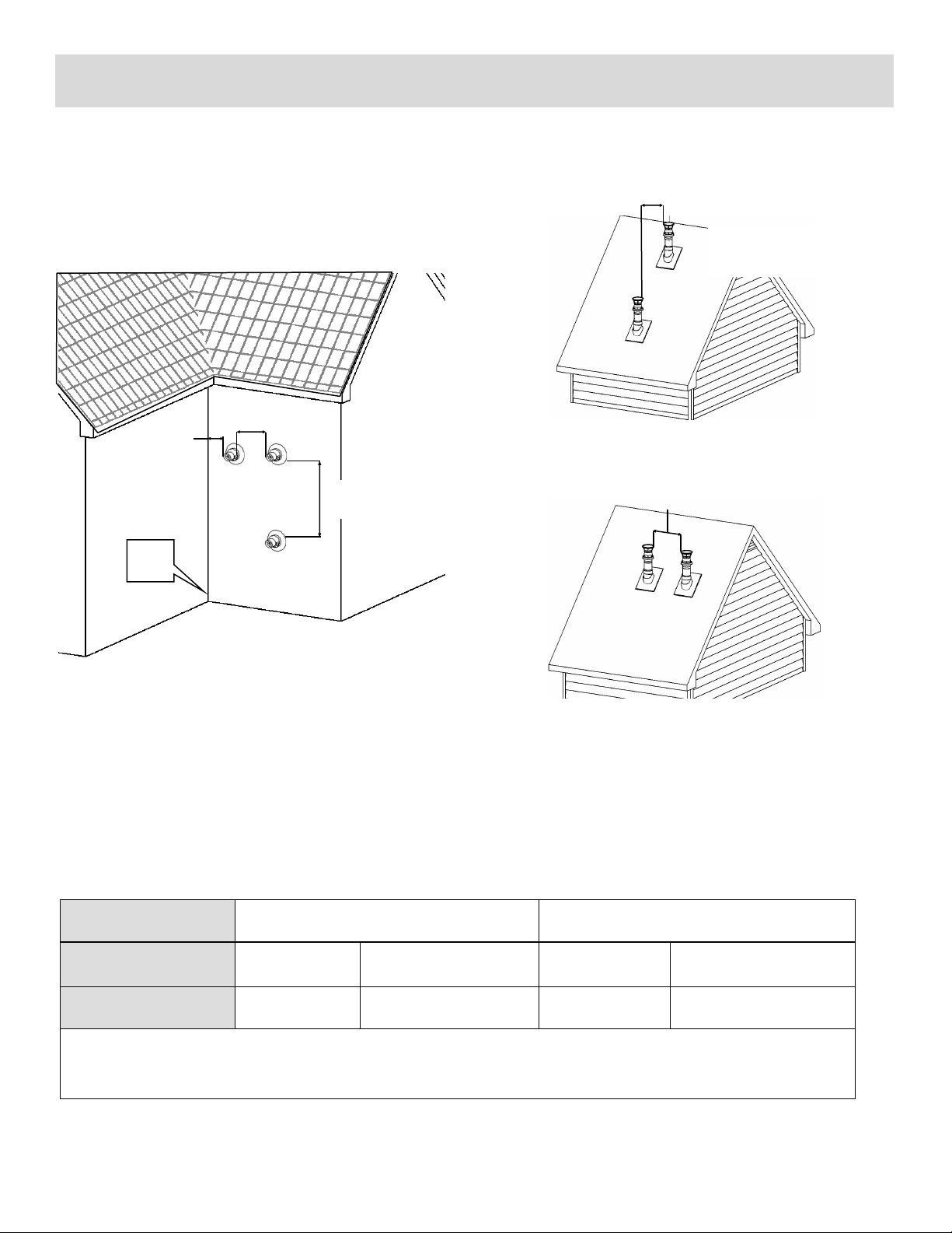
Rinnai M-Series Condensing Combi Boiler Installaon and Operaon Manual 27
CONCENTRIC PIPE: TERMINATION CLEARANCES
Vent Sizes 3 in. X 5 in. 2 in. X 4 in.
Boiler Model Number M060C M090C, M120C, M160C M060C M090C, M120C, M160C
Vent Lengths 60 (18 m) 30 (9 m) 150 (46 m) 140 (43 m)
• 45° elbow is equivalent to 3 (1 m)
• 90° elbow is equivalent to 6 (2 m)
CONCENTRIC PIPE: MAXIMUM EQUIVALENT VENT LENGTH
All terminaons (horizontal and/or vercal) must terminate 12 in. (0.30 m) above grade or ancipated snow level.
12 in. (0.30 m)
Between terminals at same level
60 in. (1.52 m)
Between terminals at dierent levels
Note: 24 in. (0.61 m)
to wall or parapet
Inside
Corner
12 in.
(0.30 m)
12 in.
(0.30 m)
60 in. (1.52 m) vercally
between terminals
Direct Vent: Concentric Pipe
Page 28
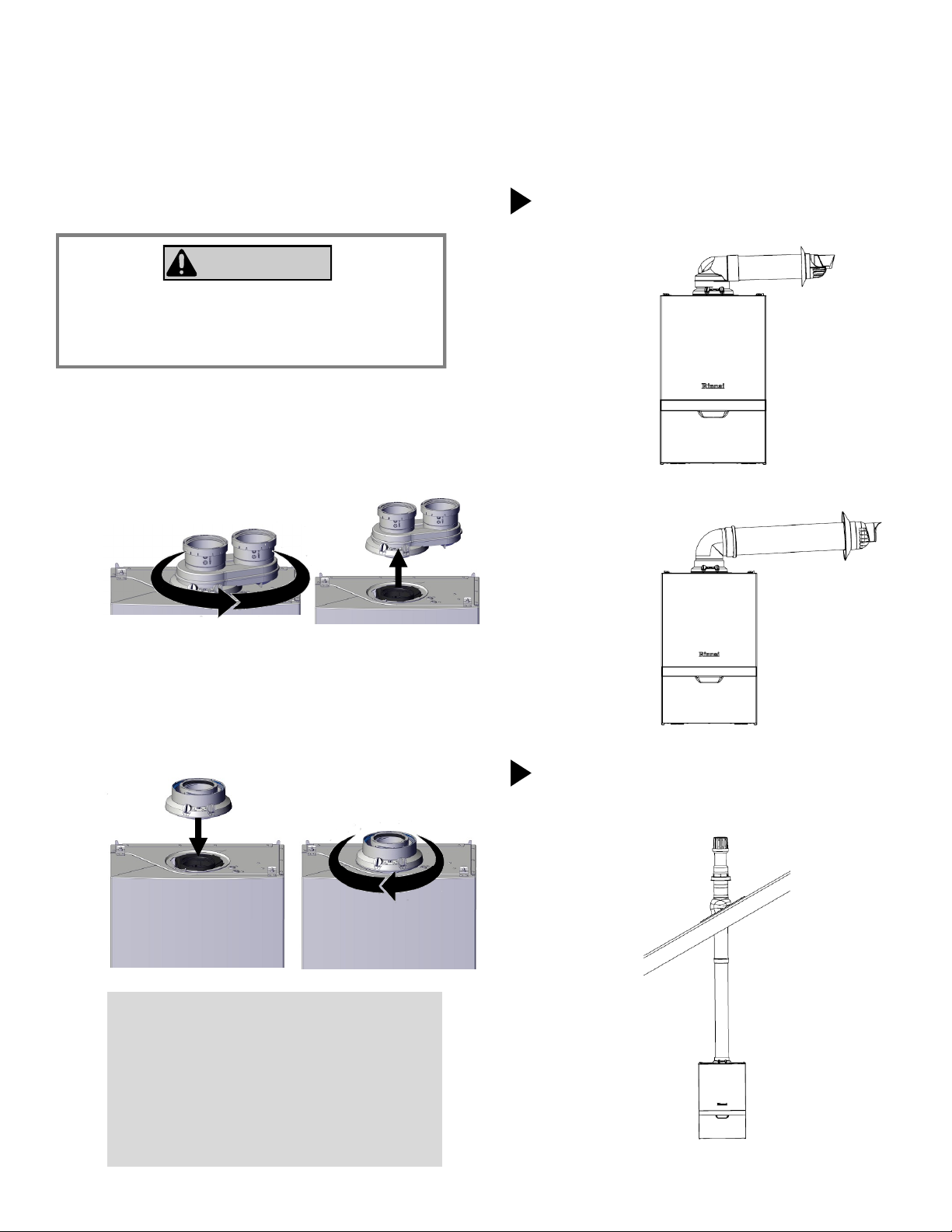
28 Rinnai M-Series Condensing Combi Boiler Installaon and Operaon Manual
CONCENTRIC PIPE:
INSTALLATION INSTRUCTIONS
2 in. x 4 in.
3 in. x 5 in.
2 in. x 4 in.
and
3 in. x 5 in.
Important: Install the venng terminaon
according to the diagrams and instrucons in
this manual. Slope the venting 1/4 in. per foot
toward the appliance according to the vent
manufacturer’s installation instructions.
Dispose of condensate per local codes.
The instrucons below apply to concentric vent sizes
2 in. x 4 in. and 3 in. x 5 in.
CONCENTRIC PIPE:
EXAMPLE VENT APPLICATIONS
Horizontal Wall Terminaons
Vercal Roof Terminaons
1
2
Insert the concentric adapter and rotate
clockwise unl locked in place.
Remove the vent top (slightly twist counterclockwise and pull up). Discard vent top if
desired.
Pull up
Slightly twist
counter-clockwise
Improper installaon of vent components, or failure
to follow all installaon instrucons can result in
property damage, personal injury, or death.
WARNING
Page 29
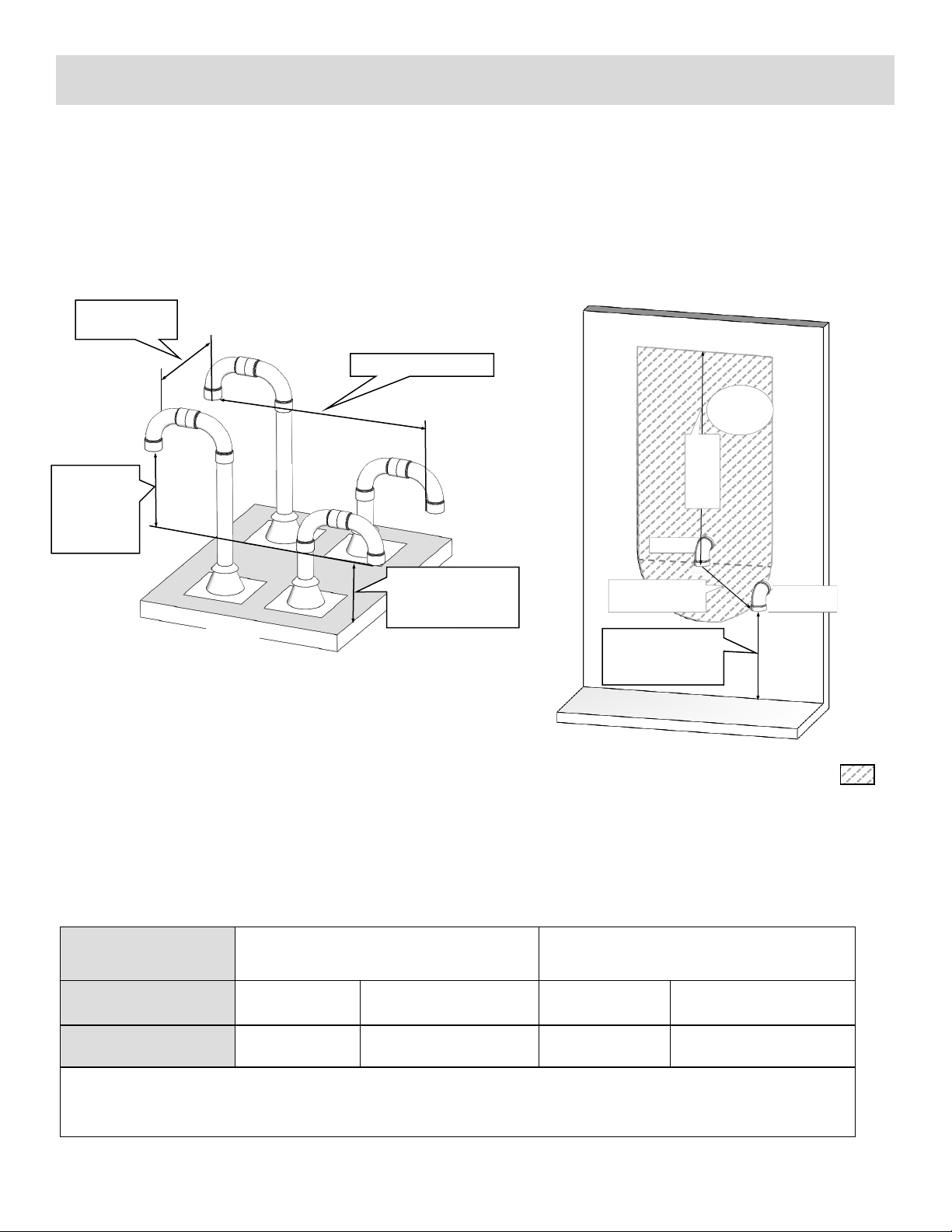
Rinnai M-Series Condensing Combi Boiler Installaon and Operaon Manual 29
Twin Pipe Vercal Terminaon
of Mulple Boilers
Combuson air terminaon not permied in shaded area
12 in. (0.30 m) above
grade or ancipated
snow level
12 in. (0.30 m) minimum
12 in. (0.30 m)
minimum
above
combuson air
opening
Roof
12 in. (0.30 m) above
grade or ancipated
snow level
12 in. (0.30 m)
minimum
Exhaust
Combuson
Air
Exhaust
Zone
60 in. (1.5 m)
minimum
12 in. (0.30 m)
minimum
Wall
Combuson
Air
Exhaust
Vent Sizes
• 3 in. PVC
• 3 in. (80 mm) PP
• 2 in. PVC
• 2 in. (60 mm) PP
Boiler Model Number M060C M090C, M120C, M160C M060C M090C, M120C, M160C
Vent Lengths 60 (18 m) 30 (9 m) 150 (46 m) 140 (43 m)
• 45° elbow is equivalent to 3 (1 m)
• 90° elbow is equivalent to 6 (2 m)
Direct Vent: Twin Pipe
TWIN PIPE: TERMINATION CLEARANCES
TWIN PIPE: MAXIMUM EQUIVALENT VENT LENGTH
Horizontal Vent and
Combuson Air Piping
Page 30
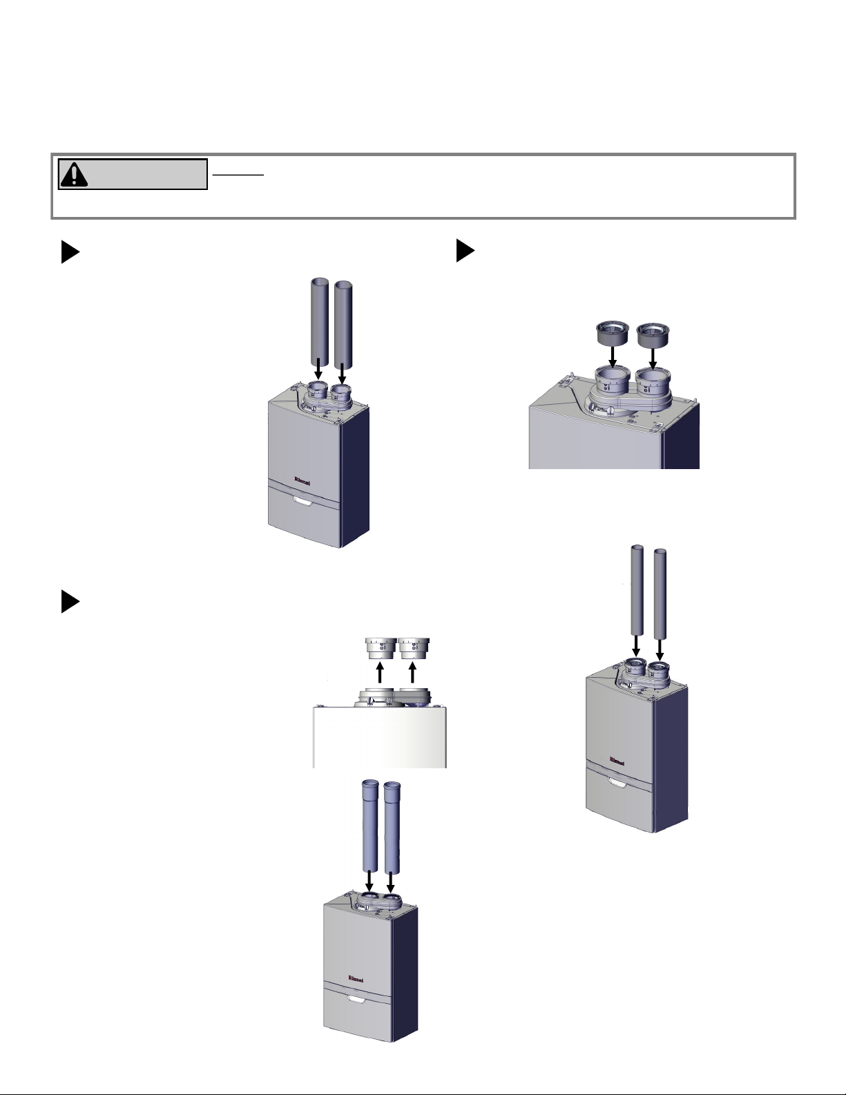
30 Rinnai M-Series Condensing Combi Boiler Installaon and Operaon Manual
This boiler is equipped with a 3 in. PVC pipe connecon. With the use of a pipe reducer, installers can use a
2 in. pipe for the combuson air and exhaust.
DO NOT apply PVC glues, solvents, or cleaners to the boiler’s combuson air or exhaust
gasket connecons. Failure to correctly assemble the components according to these
instrucons may result in property damage, personal injury, or death.
WARNING
TWIN PIPE: INSTALLATION INSTRUCTIONS
Install 3 in. PVC
Install 3 in. PVC
piping.
Install 3 in. (80 mm) Polypropylene (PP)
Remove the 3 in. PVC
adapter from the vent top.
Install 2 in. PVC or PP (60 mm)
Install 2 in. PVC or PP piping.
Insert 2 in. reducer.
1
2
1
2
1
Insert 3 in. (80 mm) PP piping.
Page 31
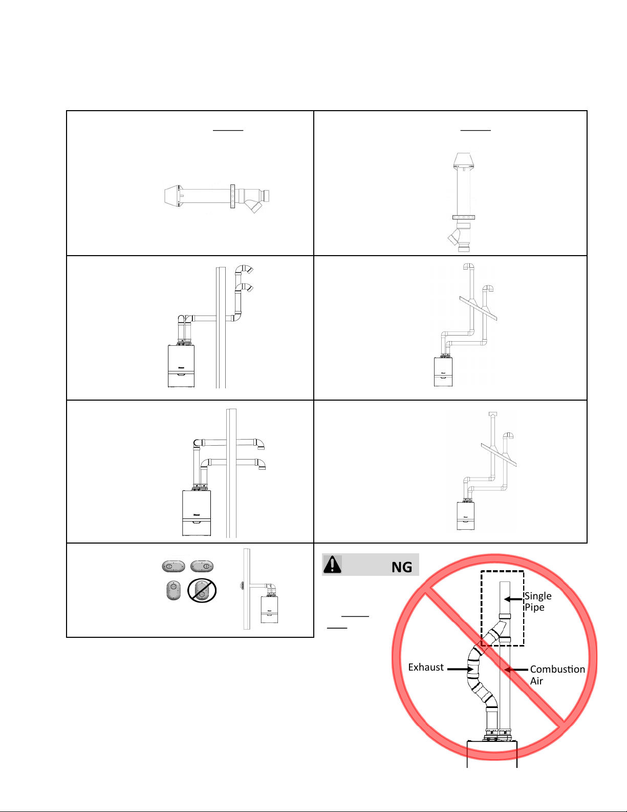
Rinnai M-Series Condensing Combi Boiler Installaon and Operaon Manual 31
2 in. or 3 in.
PVC/CPVC
IPEX/Royal
Concentric
Side Wall
Terminaon
Congura-
on
2 in. or 3 in.
PVC/CPVC
IPEX/Royal
Concentric
Vercal
Terminaon
Conguraon
2 in. or 3 in.
Schedule 40
PVC/CPVC
Snorkel
Terminaon
Congura-
on
2 in. or 3 in.
Schedule 40
PVC/CPVC
Standard
upside down
"U" Vercal
Terminaon
Conguraon
2 in. or 3 in.
Schedule 40
PVC/CPVC
Elbow or Tee
Side Wall
Terminaon
Congura-
on
2 in. or 3 in.
Schedule 40
PVC/CPVC Tee
Vercal
Terminaon
Conguraon
2 in. or 3 in.
PVC Low
Prole
Terminaon
Congura-
on
This conguraon requires the use of
a Concentric Vent Terminaon
Exhaust and
combuson
air MUST
NOT be
brought
together into
a single PVC
pipe using a
pipe ng.
WARNING
Slope horizontal exhaust 1/4 in. per foot towards the boiler. DO NOT slope combuson air pipe towards the boiler.
Exhaust
Combuson
Air
Single
Pipe
This conguraon requires the use of
a Concentric Vent Terminaon
TWIN PIPE: EXAMPLE VENT APPLICATIONS
Page 32
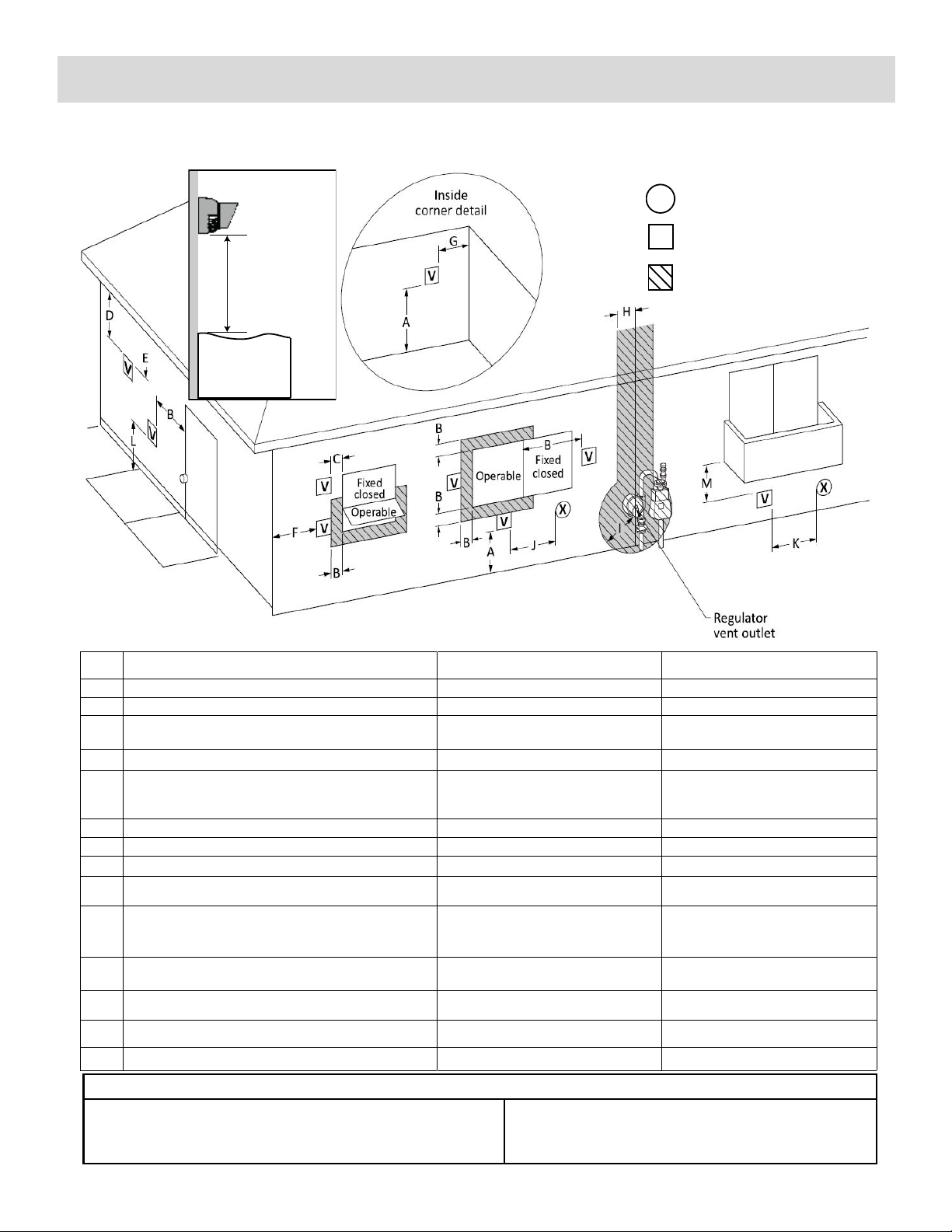
32 Rinnai M-Series Condensing Combi Boiler Installaon and Operaon Manual
Canadian Installaons
(CSA B149.1)
U.S. Installaons
(ANSI Z223.1 /NFPA 54)
Ref Descripon Other than Direct Vent (Room Air) Other than Direct Vent (Room Air)
A Clearance above grade, veranda, porch, deck, or balcony 12 in. (30 cm) 12 in. (30 cm)
B Clearance to window or door that may be opened 36 in. (91 cm)
4 (1.2 m) below or to side of opening;
1 (300 mm) above opening
C Clearance to permanently closed window * *
D
Vercal clearance to venlated sot, located above the
terminal within a horizontal distance of 2 (61 cm) from
the center line of the terminal
* *
E Clearance to unvenlated sot * *
F Clearance to outside corner * *
G Clearance to inside corner * *
H
Clearance to each side of center line extended above
meter/regulator assembly
* *
I Clearance to service regulator vent outlet
Above a regulator within 3 (91 cm)
horizontally of the vercal center line of
the regulator vent outlet to a maximum
vercal distance of 15 (4 m)
*
J
Clearance to non-mechanical air supply inlet to building or
the combuson air inlet to any other appliance
36 in. (91 cm)
4 (1.2 m) below or to side of opening;
1 (300 mm) above opening
K Clearance to a mechanical air supply inlet 6 (1.83 m)
3 (91 cm) above if within 10
(3 m) horizontally
L
Clearance above paved sidewalk or paved driveway located
on public property
7 (2.13 m) [1] *
M Clearance under veranda, porch, deck, or balcony 12 in. (30 cm) [2] *
AIR SUPPLY INLET
VENT TERMINAL
AREA WHERE TERMINAL
IS NOT PERMITTTED
X
V
SNOW
TERMINATION
Clearance in
Ref. A also
applies to
anticipated
snow line
Clearance to opposite wall is 24 in. (60 cm).
[1] A vent shall not terminate directly above a sidewalk or paved driveway that
is located between two single family dwellings and serves both dwellings.
[2] Permied only if veranda, porch, deck, or balcony is fully open on a mini-
mum of two sides beneath the oor.
Clearances are in accordance with local installaon codes and the
requirements of the gas supplier.
Room Air
ROOM AIR: TERMINATION CLEARANCES
Page 33
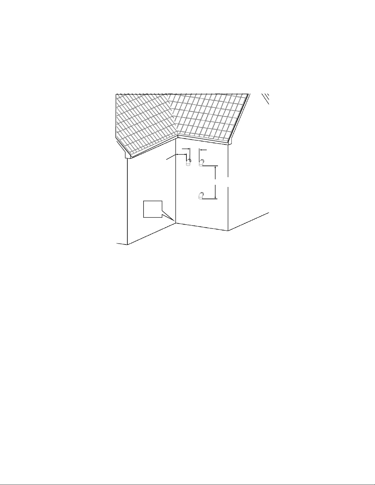
Rinnai M-Series Condensing Combi Boiler Installaon and Operaon Manual 33
60 in.
12 in.
12 in.
(0.30 m)
Inside
Corner
NOTE: All terminaons (horizontal and/or vercal) must terminate 12 in. above grade or ancipated snow level.
NOTE: Installaon of Room Air must use listed Category IV venng.
(1.52 m) vercally between terminals
ROOM AIR: EXHAUST TERMINATION CLEARANCES
Page 34

34 Rinnai M-Series Condensing Combi Boiler Installaon and Operaon Manual
Important: Combuson air must be free of corrosive chemicals. Do not provide combuson air from corrosive
environments. Appliance failure due to corrosive air is not covered by warranty.
For applicaons containing corrosive indoor air, this appliance must be installed as direct vent. DO NOT use room air in
applicaons where combuson air contains acid forming chemicals such as sulfur, uorine and chlorine. These
chemicals have been found to cause rapid damage and decay and can become toxic when used as combuson air in
gas appliances. Such chemicals can be found in, but not limited to bleach, ammonia, cat lier, aerosol sprays, cleaning
solvents, varnish, paint and air fresheners. Do not store these products or similar products in the vicinity of this boiler.
Unconned Space
An unconned space is dened in Naonal Fuel Gas Code, ANSI Z223.1/NFPA 54 as “a space whose volume is not less
than 50 cubic feet per 1000 Btu/hr (4.8 m3 per kW per hour) of the aggregate input rang of all appliances installed in
that space. Rooms communicang directly with the space in which the appliances are installed, through openings not
furnished with doors, are considered a part of the unconned space.” If the “unconned space” containing the
appliance(s) is in a building with ght construcon, addional outside air may be required for proper operaon.
Outside air openings should be sized the same as for a conned space.
Conned Space
A conned space is dened in the Naonal Fuel Gas Code, ANSI Z223.1/NFPA 54 as "a space whose volume is less than
50 cubic feet per 1000 Btu/hr (4.8 m3 per kW per hour) of the aggregate input rang of all appliances installed in that
space." Examples include a small room, closet, alcove, ulity room, etc. A conned space must have two combuson
air openings. Size the combuson air openings based on the BTU input for all gas ulizaon equipment in the space
and the method by which combuson air is supplied.
Using Indoor Air For Combuson
When using air from other room(s) in the building, the total volume of the room(s) must be of adequate volume
(Greater than 50 cubic feet per 1000 Btu/hr). Combuson air openings between joining rooms must have at least 1
square inch of free area for each 1000 Btu/h, but not less than 100 square inches each.
Using Outdoor Air For Combuson
Outdoor air can be provided to a conned space through two permanent openings, one commencing within 12 in.
(0.30 m) of the top and one commencing within 12 in. (0.30 m) of the boom, of the conned space. The openings
shall communicate to the outside by one of two ways.
When communicang directly with the outdoors through horizontal ducts, each opening shall have a minimum free
area of 1 in2/2000 Btu/hr (1100 mm2/kW) of total input rang of all appliances in the conned space.
Note: If ducts are used, the cross seconal area of the duct must be greater than or equal to the required free area of
the openings to which they are connected.
This boiler requires adequate combuson air for venlaon and diluon of ue gases. Failure to provide
adequate combuson air can result in unit failure, re, explosion, serious bodily injury or death. Use the following
methods to ensure adequate combuson air is available for correct and safe operaon of this boiler.
WARNING
ROOM AIR: COMBUSTION AIR
Page 35
Rinnai M-Series Condensing Combi Boiler Installaon and Operaon Manual 35
Combuson air provided to the appliance should not be taken from any area of the structure that may produce a
negave pressure (i.e. exhaust fans, powered venlaon fans).
NOTICE
WARNING
TO PREVENT POSSIBLE PERSONAL INJURY OR DEATH DUE TO ASPHYXIATION, COMMON VENTING WITH OTHER
MANUFACTURER’S INDUCED DRAFT APPLIANCES IS NOT ALLOWED.
Locaon
To maintain proper circulaon of combuson air two permanent
openings (one upper, one lower) must be posioned in conned
spaces. The upper shall be within 12 in. (0.30 m) of the top of the
conned space and the lower opening shall be within 12 in. (0.30 m) of
the boom of the conned space. Openings must be posioned as to
never be obstructed.
Louvers and Grills
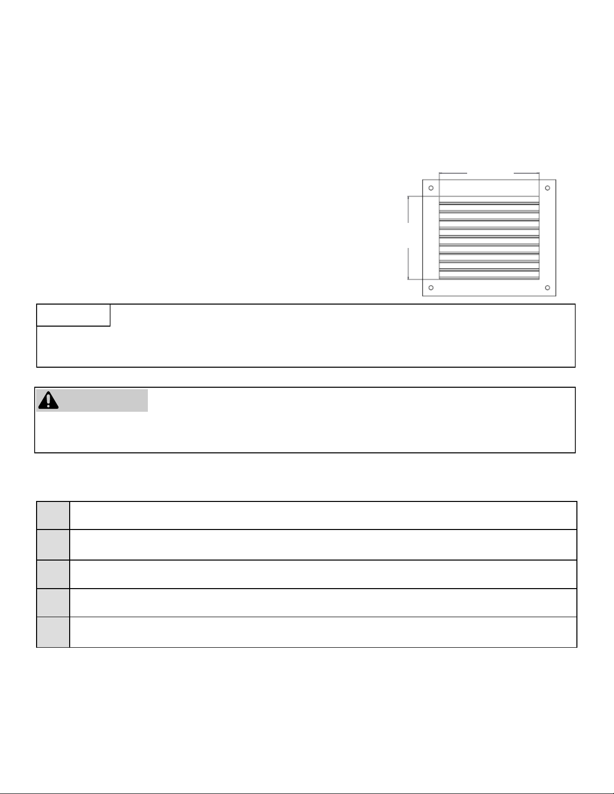
When sizing the permanent opening consideraon must be taken for the design of the louvers or grills to maintain the
required free area required for all gas ulizing equipment in the space. If the free area of the louver or grill design is
not available, assume wood louvers will have 25% free area and metal louvers or grills will have 75% free area. Under
no circumstance should the louver, grill or screen have openings smaller than 1/4 in.
Examples: Wood: 10 in. x 12 in. x 0.25 = 30 in.
2
Metal: 10 in. x 12 in. x 0.75 = 90 in.2
12 in.
(300 mm)
10 in.
(250 mm)
□
Verify all combuson air opening sizes are correct.
□
Ensure that the Combuson Air Requirements are followed that will provide sucient combuson air for the
appliance.
□
DO NOT use room air for combuson in applicaons where the indoor air is corrosive.
□
Verify that adequate combuson air is available for all appliances installed in the space.
□
Installaon complies with Naonal Fuel Gas Code, ANSI Z223.1/NFPA 54 as well as local and state
regulaons therein.
CHECKLIST FOR COMBUSTION AIR AND VENTING REQUIREMENTS
Page 36
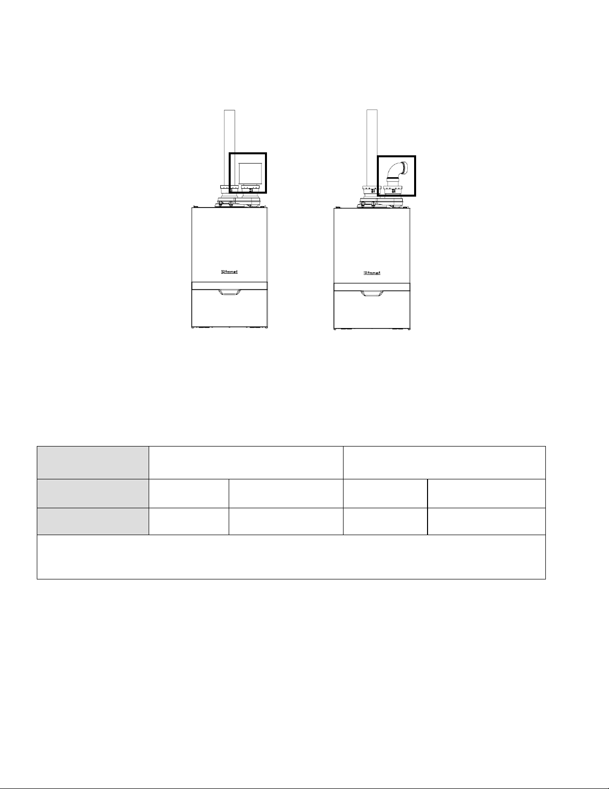
36 Rinnai M-Series Condensing Combi Boiler Installaon and Operaon Manual
Vent Sizes
• 3 in. PVC
• 3 in. (80 mm) PP
• 2 in. PVC
• 2 in. (60 mm) PP
Boiler Model Number M060C M090C, M120C, M160C M060C M090C, M120C, M160C
Vent Lengths 60 (18 m) 30 (9 m) 150 (46 m) 140 (43 m)
• 45° elbow is equivalent to 3 (1 m)
• 90° elbow is equivalent to 6 (2 m)
Insert air lter or elbow into 3 in. PVC intake air ng.
ROOM AIR: INSTALLATION INSTRUCTIONS
ROOM AIR: MAXIMUM EQUIVALENT VENT LENGTH
Air Filter Elbow
Page 37
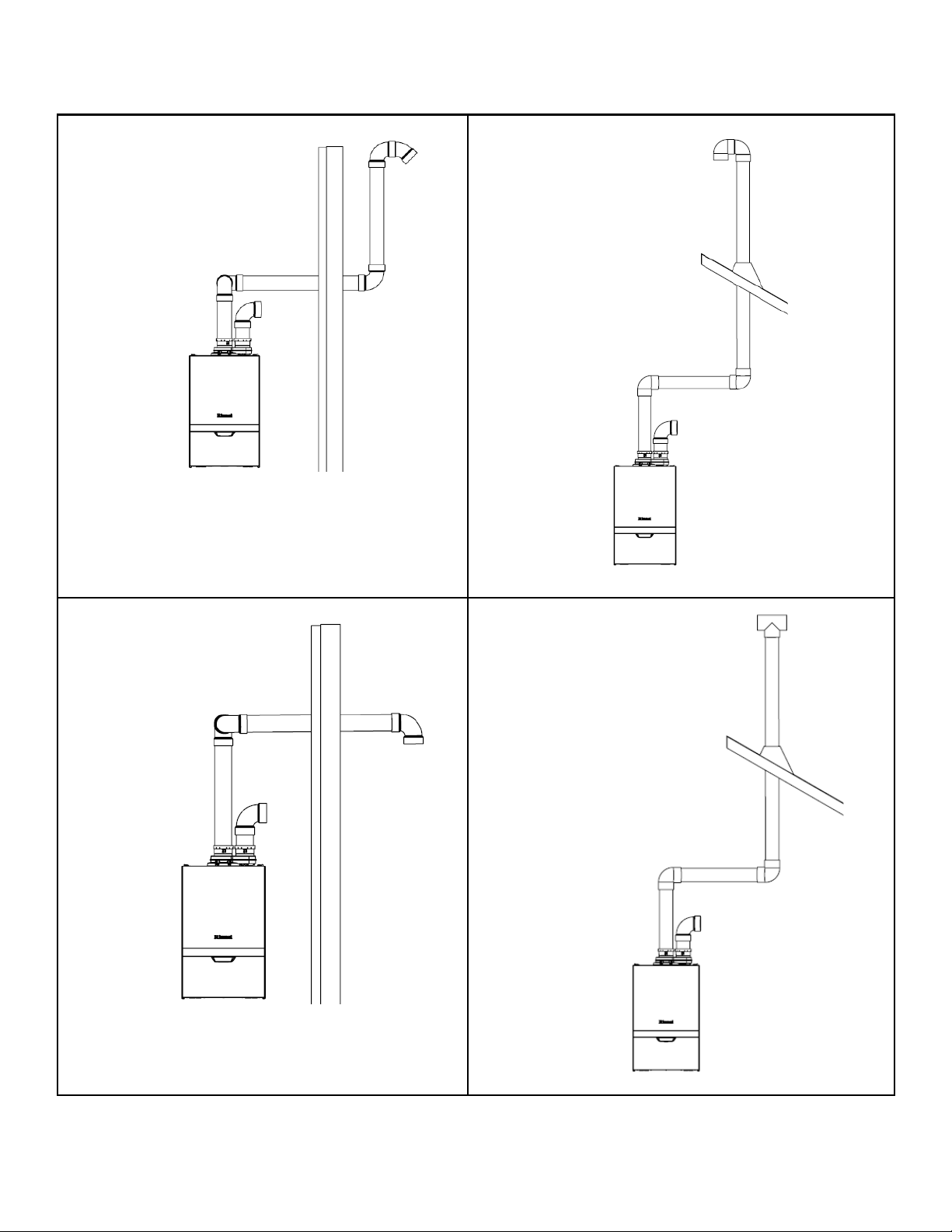
Rinnai M-Series Condensing Combi Boiler Installaon and Operaon Manual 37
2 in. or 3 in.
Schedule 40
PVC/CPVC
Snorkel
Terminaon
Conguraon
2 in. or 3 in.
Schedule 40
PVC/CPVC
Standard
Upside Down
"U" Vercal
Terminaon
Conguraon
2 in. or 3 in.
Schedule 40
PVC/CPVC
Elbow or Tee
Side Wall
Terminaon
Conguraon
2 in. or 3 in.
Schedule 40
PVC/CPVC
Tee Vercal
Terminaon
Conguraon
Slope horizontal exhaust 1/4 in. per foot towards the boiler.
ROOM AIR: EXAMPLE VENT APPLICATIONS
Page 38
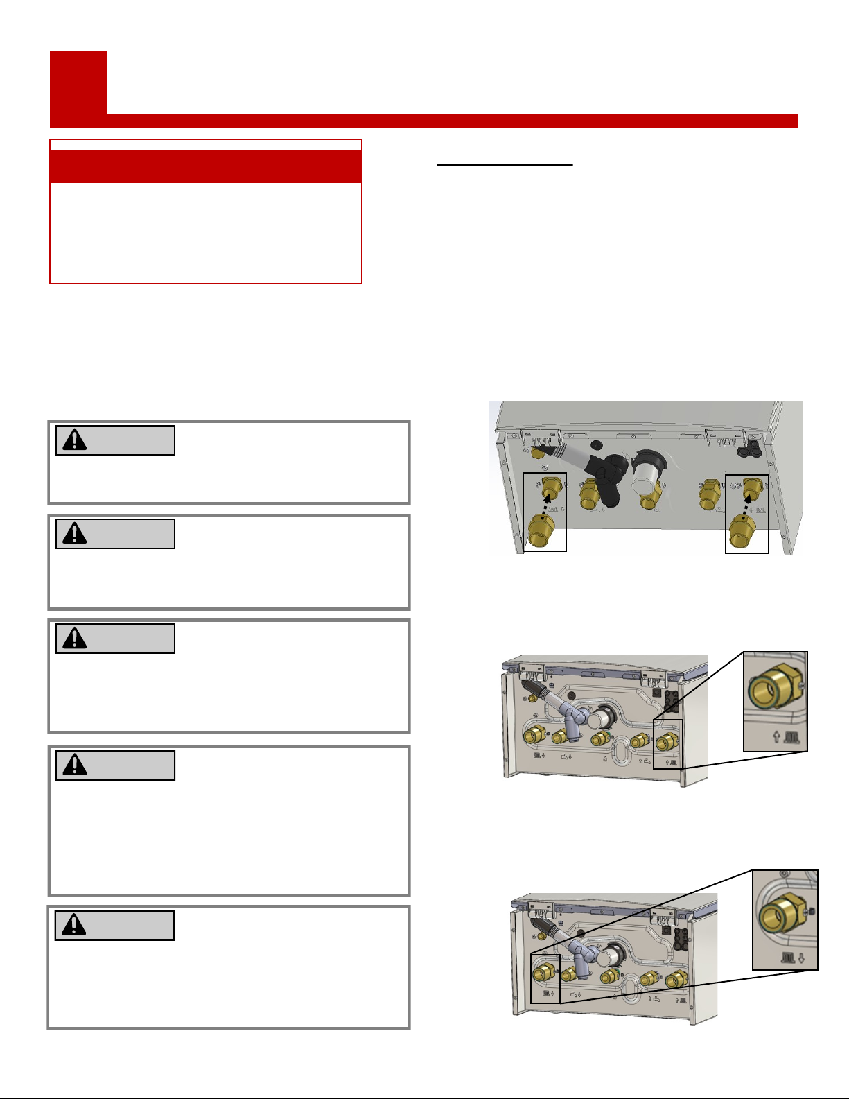
38 Rinnai M-Series Condensing Combi Boiler Installaon and Operaon Manual
Plumb the heang supply line to the heang supply
connecon on the boom of the boiler.
When removing the plasc sealing caps from the pipes,
water may come out of the boiler due to live re tesng
during manufacturing.
NOTICE
The boiler, when used in connecon with a refrigeraon
system, must be installed so the chilled medium is piped
in parallel with the boiler with appropriate valves to
prevent the chilled medium from entering the boiler.
NOTICE
The boiler piping system of a hot water boiler
connected to heang coils located in air handling units
where they may be exposed to refrigerated air
circulaon must be equipped with ow control valves or
other automac means to prevent gravity circulaon of
the boiler water during the cooling cycle.
NOTICE
Some installaons with mulple zone valves may
require a dierenal bypass, which will prevent
excessively high ow rates through a single zone when
the other zone valves are closed.
NOTICE
Heang Return Connecon
Heang Supply Connecon
System Piping
6
Piping for Central
Heang Systems
Instrucons
Topics in this secon
• Piping for Central Heang Systems
• Piping for DHW Systems
• Connect the Condensate Drain Line
• Connect the Pressure Relief Valves
Purge the water line to remove all debris and air. Debris
will damage the boiler.
NOTICE
1
To connect the water supply, follow the instrucons
below.
IMPORTANT: Water connecons to the boiler should
follow all state and local plumbing codes.
If this is a standard installaon, refer to the “Piping
Diagram for Basic Central Heang Installaon” on the
next page.
Aach the 3/4 in. FNPT x 1 in. MNPT
connecon ng to the supply and return
heang ngs on the boom of the boiler.
Supply and Return Fing Connecons
Plumb the heang return line to the heang
return connecon on the boom of the boiler.
2
3
Page 39
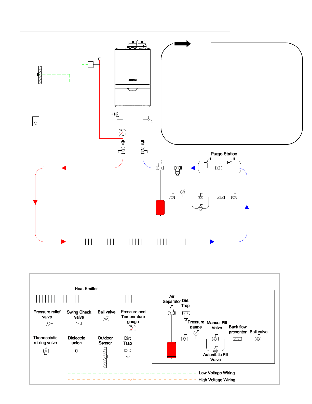
Rinnai M-Series Condensing Combi Boiler Installaon and Operaon Manual 39
This is not an engineering drawing; it is intended only as a guide and not as a replacement for professional engineering project drawings. This
drawing is not intended to describe a complete system. It is up to the contractor or engineer to determine the necessary components and
conguraon of the parcular system to be installed. The drawing does not imply compliance with local building code requirements. It is the
responsibility of the contractor or engineer to ensure the installaon is in accordance with all local building codes. Confer with local building
ocials before installaon.
Heat Emier
Thermostat
Outdoor
Reset
Oponal Low Water
Cut-O (LWCO)
Piping Diagram for a Basic Central Heang System
This picture illustrates a suggested
arrangement. Some of the ngs
are oponal.
LEGEND
NOTE
This schemac shows a simple single zone system
without an external system circulator (not including the
circulator located inside the boiler). If an external
circulator is present, a primary/secondary system is
required. This type of boiler connecon may also be
necessary in a mulple zone applicaon.
Primary/secondary piping is necessary in the following
applicaons: when using external pumps; large zoned
systems; high ow applicaons; systems with high
dierenal pressures; and systems with pressure drops
higher than 20 FT of head (see the Pressure Drop and
Water Flow Curve in secon 13 Appendices for pressure
curve informaon).
Page 40
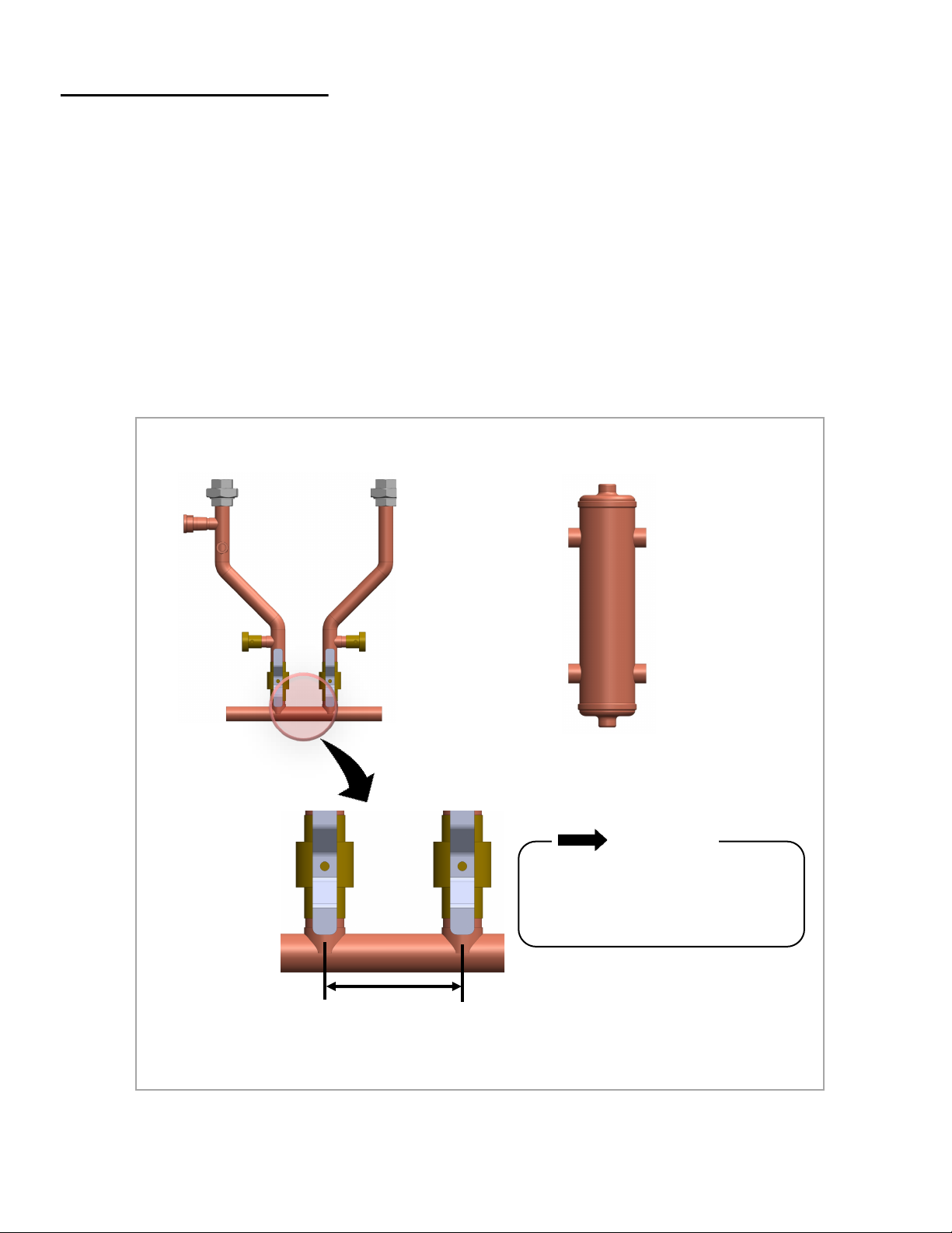
40 Rinnai M-Series Condensing Combi Boiler Installaon and Operaon Manual
In some circumstances it may become necessary to have hydraulic separaon between the boiler and the central
heang system. Hydraulic separators allow for no pump curve matching or ow calculaon; this is ideal for multemperature and mul-zone systems. Examples include:
• Systems with high pressure drops (see example below)
• Systems with high ow demands
• Systems with zone circulators
• Large zoned systems
Examples of Hydraulic Separaon
Closely spaced tees and low loss headers are common examples of hydraulic separators and can be used to separate
the boiler loop from the central heang loop.
Closely Spaced Tees Low Loss Header
Distance no
more than four
pipe diameters
IMPORTANT
For closely spaced tee installaons,
the separaon at the header is to be
no more than four pipe diameters.
Hydraulic Separaon
Page 41
Rinnai M-Series Condensing Combi Boiler Installaon and Operaon Manual 41
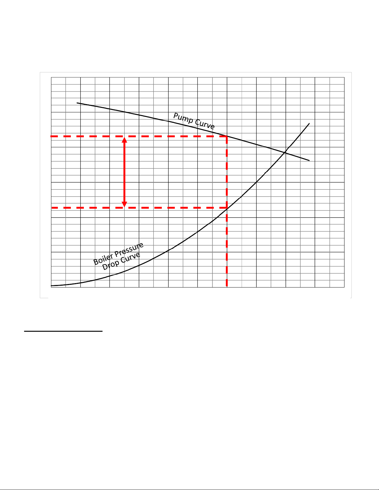
Example: If there is a 6 GPM system ow demand, there would be approximately 10 of head available for the system.
If more pressure drop is present in the central heang system, a means of hydraulic separaon is necessary.
0 1 2 3 4 5
6
7 8
9
10
20
15
25
30
10
5
0
Water Flow (GPM)
Pressure Loss (Feet of Head)
Pressure Drop and Water Flow Curve with Hydraulic Separaon
Internal Bypass
There is an internal bypass valve located in the supply side of the water control assembly. This allows for internal
circulaon inside the boiler to ensure there is always water ow present. In high resistance applicaons, the valve may
open to ensure proper temperature across the boiler loop.
Page 42
42 Rinnai M-Series Condensing Combi Boiler Installaon and Operaon Manual
• A thermostac mixing valve shall be installed on all
M-Series Combi boilers on the domesc hot water
side to prevent scalding; this valve regulates the
water temperature leaving the brazed plate heat
exchanger.
• The piping (including soldering materials) and
components connected to this appliance must be
approved for use in potable water systems.
• Purge the water line to remove all debris and air.
Debris will damage the boiler.
• The appliance must not be connected to a system
that was previously used with a non-potable water
heang appliance.
• DO NOT introduce toxic chemicals such as those used
for boiler water treatment to the potable water used
for central heang.
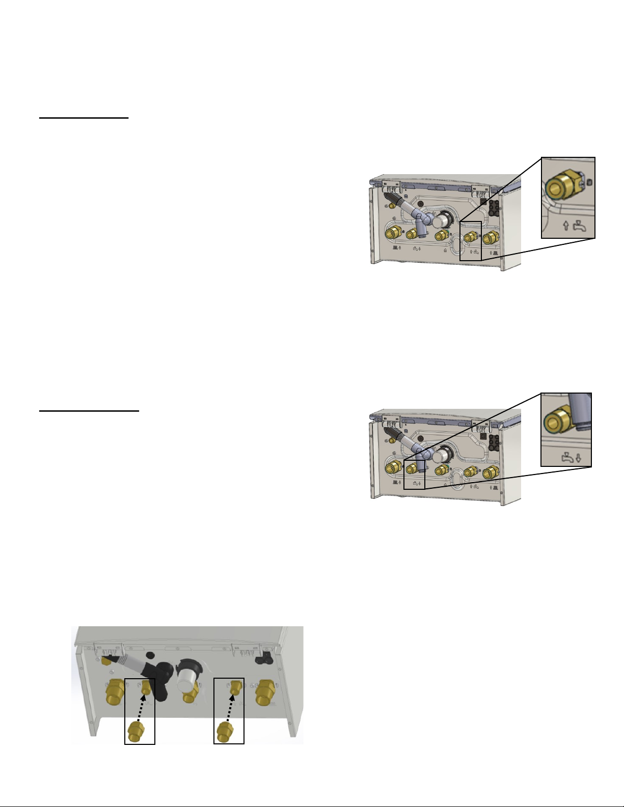
DHW Cold Inlet Connecon
DHW Hot Outlet Connecon
Guidelines
Instrucons
Piping for DHW Systems
Aach the 1/2 in. FNPT x 3/4 in. MNPT
connecon ng to the hot and cold ngs
on the boom of the boiler.
To connect the water supply, follow the instrucons
below.
IMPORTANT: Water connecons to the boiler should
follow all state and local plumbing codes.
If this is a standard installaon, refer to the Piping
Diagram for Basic DHW Installaon on the next page.
1
2
3
Plumb the cold water supply line to the
DHW cold inlet connecon on the boom of
the boiler.
Plumb the hot water supply line to the DHW
hot outlet connecon on the boom of the
boiler.
Hot and Cold Fing Connecons
Page 43
Rinnai M-Series Condensing Combi Boiler Installaon and Operaon Manual 43
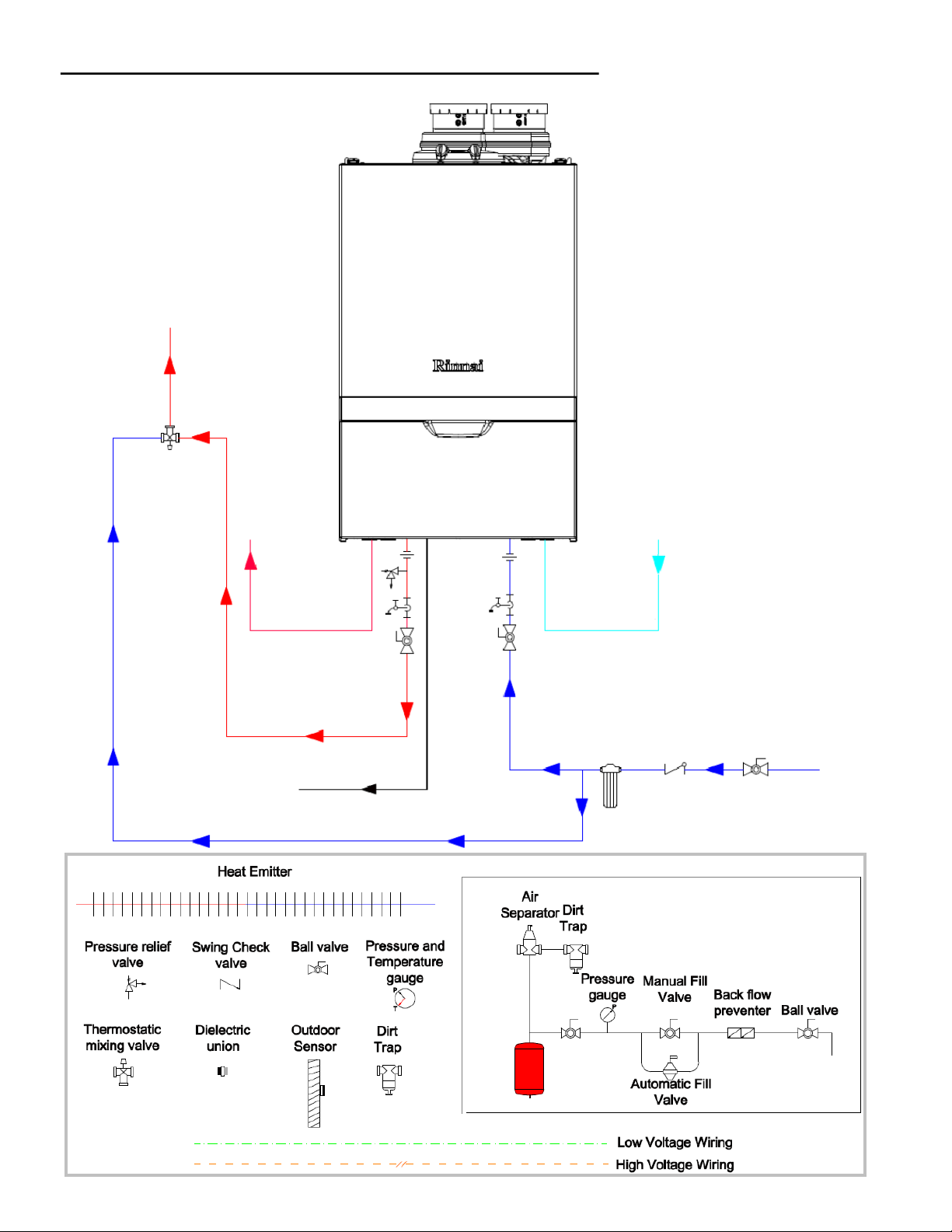
Piping Diagram for Basic DHW Installaon
This picture illustrates a suggested
arrangement. Some of the ngs
are oponal.
LEGEND
Cold Water Supply Line
Heang Return
Hot Water Supply Line
Condensate Drain Line
Sediment Filter (Recommended)
Mixing Valve
Heang Supply
Tempered Hot Water
Supply to Fixtures
This is not an engineering drawing; it is intended
only as a guide and not as a replacement for
professional engineering project drawings. This
drawing is not intended to describe a complete
system. It is up to the contractor or engineer to
determine the necessary components and
conguraon of the parcular system to be
installed. The drawing does not imply compliance
with local building code requirements. It is the
responsibility of the contractor or engineer to
ensure the installaon is in accordance with all
local building codes. Confer with local building
ocials before installaon.
Page 44
44 Rinnai M-Series Condensing Combi Boiler Installaon and Operaon Manual
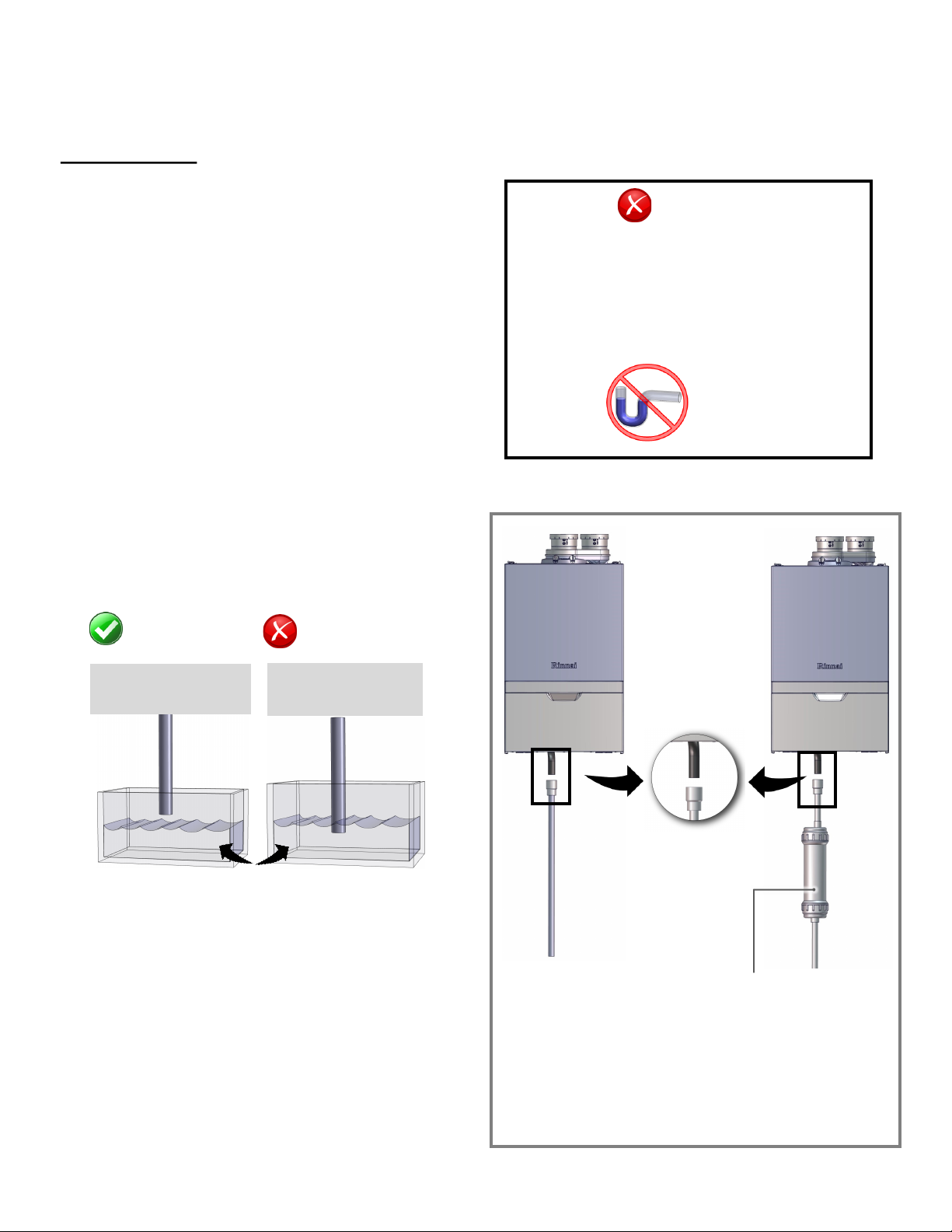
• Do not plumb the condensate drain with the
pressure relief valve; both must be plumbed
independently to drain.
• All condensate must drain and be disposed of
according to local codes.
• Use only corrosion resistant materials for the
condensate drain lines such as PVC pipe or
plasc hose.
• The condensate drain pipe (along its enre
length) must be at least 1/2 in.
• Condensaon drain lines installed in areas that
are subject to freezing temperatures should
be wrapped with an approved supplemental
heat source. Install per manufacturer’s
instrucons.
• Slope the condensate drain lines toward the
inside oor drain or condensate pump.
• The end of the condensate drain pipe should
be open to the atmosphere. The end should
not be under water or other substances.
EXTERNAL TRAP
NOT REQUIRED
DO NOT
• DO NOT connect the condensate drain line
with an air condioning evaporator coil drain.
• Boilers have an integrated condensate trap.
DO NOT install an external condensate trap.
Connect the Condensate Drain Line
Guidelines
• If a oor drain is not available or the drain is
above the level of the condensate drain, a
condensate pump should be installed.
• A condensate neutralizer kit is available from
Rinnai. The kit allows condensate to ow
through neutralizing media that raises the pH
of the condensate to a level that will help prevent corrosion of the drain and public sewer
system. Refer to the Accessories secon for
more informaon.
• The condensate drain pipe should be as short
as possible and have a downward pitch.
Refer to Neutralizer
Installaon Manual and
local codes for
neutralizer installaon
guidelines.
Neutralizer
Pipe open to
atmosphere
CORRECT
Pipe open to
atmosphere
Pipe submerged
in water
NOT
CORRECT
Water level
Image is for reference purposes only
Page 45
Rinnai M-Series Condensing Combi Boiler Installaon and Operaon Manual 45
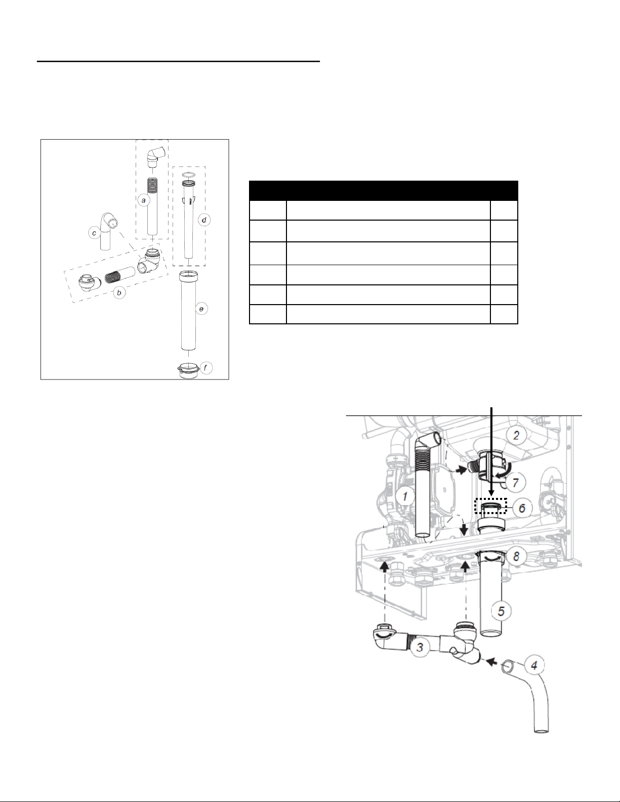
Connect the Condensate Drain Kit
Verify Contents
Item # Item Qty
a Elbow with exible pipe 1
b T-piece, elbow and exible pipe assembly 1
c Flexible drain pipe 1
d Condensate drain inner tube 1
e Condensate drain outer tube 1
f Condensate collector cover 1
Mul-purpose grease or lubricant
Tools/Materials Required
Figure 1
Apply grease or lubricant
to top of o-ring
Reference Figure 1 for the following instrucons.
1. Press and turn the assembly (3), with the elbow rst, in the
corresponding holes in the boom plate of the boiler.
2. Press the black exible pipe (1) from inside the boiler in the
rubber T-piece (3).
3. Press the black rubber elbow with exible drain pipe (1) on the
condensate tray (2).
4. Lead the long black exible pipe (4) through the free hole of the
boiler frame and press it in the T-piece (3).
5. Lead the other end of the exible pipe outside the boiler to the
drain.
6. Fill the condensate drain outer tube (5) with 150 ml (about 5
oz.) of water.
7. Apply mul-purpose grease or lubricant to the top of the o-ring
on the condensate drain inner tube (6).
8. Insert the condensate drain inner tube (6) through the hole in
the boom plate of the boiler into the condensate tray (2) of
the heat exchanger; you will hear a click when it is fully seated.
Next, insert the condensate drain outer tube through the hole.
Secure the condensate drain out tube with the securing clip (7)
by turning it clockwise.
9. Press the sealing ring (8) around the outer condensate tube and
press/turn it in the boom plate of the boiler.
Instrucons
Page 46
46 Rinnai M-Series Condensing Combi Boiler Installaon and Operaon Manual
An approved pressure relief valve is required by the American Naonal Standard (ANSI Z21.13) for all water heang
systems and shall be accessible for servicing. When connecng a pressure relief valve, follow the guidelines below:
• The M-Series boiler has a factory-installed pressure sensor type low water cut o (LWCO). Check your local codes
to determine if a low water cut o is required and if this device conforms to the local code. The boiler's internal
low water cut o is not serviceable or adjustable.
• The pressure relief valve must comply with the standard for Relief Valves and Automac Gas Shuto Devices for
Hot Water Supply Systems ANSI Z21.22 and /or the standard Temperature, Pressure, Temperature and Pressure
Relief Valves and Vacuum Relief Valves, CAN1-4.4.
• The pressure relief valve must be rated up to 150 psi for DHW systems and 30 psi for central heang systems, and
to at least the maximum BTU/hr of the appliance.
• The discharge from the pressure relief valve should be piped to the ground or into a drain system per local codes.
• The pressure relief valve must be manually operated once a year to check for correct operaon.
• The discharge line from the pressure relief valve should pitch downward and terminate 6 in. (152 mm) above
drains where discharge will be clearly visible.
• The discharge end of the line shall be plain (unthreaded) and a minimum of 3/4 in. nominal pipe diameter. The
discharge line material must be suitable for water at least 180° Fahrenheit.
• The pressure relief valve is assembled to the pressure relief valve adapter as illustrated on the next page. DO NOT
place any other valve or shut o device between the pressure relief valve and the boiler.
• If a pressure relief valve discharges periodically, this may be due to thermal expansion in a closed water supply
system. Contact the water supplier or local plumbing inspector on how to correct this situaon. Do not plug the
pressure relief valve.
• The American Naonal Standard (ANSI Z21.13) does not require a combinaon temperature and pressure relief
valve for this appliance. However, local codes may require a combinaon temperature and pressure relief valve.
• Protect pressure relief valve and pressure relief valve discharge line from freezing. Do not plug or restrict ow of
the pressure relief valve.
Water discharged from the pressure relief valve could cause severe burns instantly or death
from scalds.
DO NOT plumb the pressure relief valve with the condensate drain; both must be plumbed
independently to drain.
DO NOT plug the pressure relief valve and do not install any reducing ngs or other restricons in the relief
line. The pressure relief line should allow for complete drainage of the valve and the line.
DO NOT place any other valve or shuto device between the pressure relief valve and the boiler.
WARNING
An ASME 30 psi safety pressure relief valve is included with the boiler and must be ed before any shut o valve in
the system.
Connect the Pressure Relief Valves
(For DHW and Central Heang)
General Guidelines for Central Heang and DHW
Central Heang Systems
Page 47
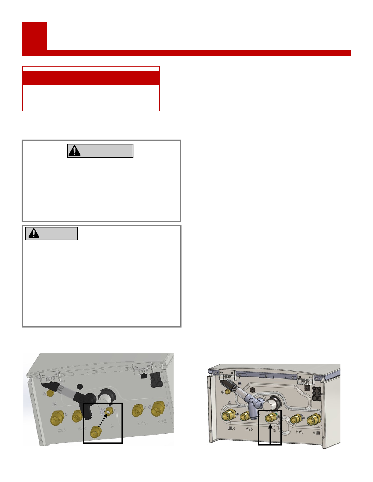
Rinnai M-Series Condensing Combi Boiler Installaon and Operaon Manual 47
1. Aach the 1/2 in. FNPT x 3/4 in. MNPT connecon
ng to the gas ng on the boom of the boiler.
• A licensed professional must install the gas supply.
• Turn o 120V power supply.
• Turn o the gas.
• Gas is ammable. Do not smoke or provide other
ignion sources while working with gas.
• Do not turn on the boiler or gas unl all fumes are
gone.
WARNING
2. Check the type of gas and gas supply pressure before
connecng the boiler. If the boiler is not of the gas
type that the building is supplied with, DO NOT
connect the boiler. Contact the dealer for the proper
boiler to match the gas type.
3. Check the gas supply pressure immediately upstream
at a locaon provided by the gas company. Supplied
gas pressure must be within the limits shown in the
Specicaons secon with all gas appliances
operang.
4. Before placing the appliance in operaon, all joints
including the heater must be checked for gas
ghtness by means of soap, gas leak detector
soluon, or an equivalent nonammable soluon, as
applicable. (Since some leak test soluons, including
soap and water, may cause corrosion or stress
cracking, the piping shall be rinsed with water aer
tesng, unless it has been determined that the leak
test soluon is non-corrosive.)
5. Use approved connectors to connect the boiler to the
gas line. Purge the gas line of any debris before
connecon to the boiler.
6. Any compound used on the threaded joint of the gas
piping shall be a type that resists the acon of
liqueed petroleum gas (propane/LPG).
7. The gas supply line shall be gas ght, sized, and so
installed as to provide a supply of gas sucient to
meet the maximum demand of the heater and all
other gas consuming appliances at the locaon
without loss of pressure. If in doubt about the size of
the gas line, refer to the Gas Pipe Sizing Reference
Tables secon on the next page.
8. Perform a leak and pressure test prior to operang
the boiler. If a leak is detected, do not operate the
boiler unl the leak is repaired.
Gas Supply
7
Connect the Gas Supply
Gas connecon 3/4 in. MNPT connecon
Topics in this secon
• Connect the Gas Supply
• Gas Pipe Sizing Reference Tables
• The boiler shall be installed such that the gas
ignion system components are protected from
water (dripping, spraying, rain, etc.) during
appliance operaon and service (circulator
replacement, condensate trap, control replacement,
etc.).
• A sediment trap must be provided upstream of the
gas controls.
• A manual gas shuto valve between the gas supply
and the boiler must be installed.
NOTICE
Gas Fing Connecon
Page 48
48 Rinnai M-Series Condensing Combi Boiler Installaon and Operaon Manual
Gas Operang Instrucons
WARNING: If you do not follow these instructions EXACTLY, a fire or explosion
may result causing property damage, personal injury or loss of life.
A. This appliance does not have a pilot. It is equipped with an ignition device which
automatically lights the burner. Do not try to light the burner by hand.
B. BEFORE OPERATING smell all around the appliance area for gas. Be sure to smell next to
the floor because some gas is heavier than air and will settle on the floor.
WHAT TO DO IF YOU SMELL GAS:
• DO NOT try to light any appliance.
• DO NOT touch any electric switch; DO NOT use any phone in your building.
• Immediately call your gas supplier from a neighbor’s phone. Follow the gas
supplier’s instructions.
• If you cannot reach your gas supplier, call the fire department.
C. Use only your hand to turn the gas control valve. Never use tools. If the gas control valve
will not turn by hand, don’t try to repair it, call a qualified service technician. Force or
attempted repair may result in a fire or explosion.
D. Do not use this appliance if any part has been under water. Immediately call a qualified
service technician to inspect the appliance and to replace any part of the control system
and any gas control which has been under water.
1. Set the temperature controller to the lowest setting.
2. Turn off all electric power to the appliance if service is to be performed.
3. Turn the manual gas control valve located at gas inlet of appliance clockwise to the
OFF position.
TO TURN OFF GAS TO APPLIANCE
1. STOP! Read the safety information above on this label.
2. Set the temperature controller to lowest setting.
3. Turn off all electric power to the appliance.
4. This appliance does not have a pilot. It is equipped with a direct ignition device which
automatically lights the burner. DO NOT try to light the burner by hand.
5. Turn the manual gas control valve located at gas inlet of appliance clockwise to the
OFF position.
6. Wait five (5) minutes to clear out any gas. Then smell for gas, including near the floor. If
you smell gas, STOP! Follow “B” in the safety information above on this label. If you don’t
smell gas, go to the next step.
7. Turn the manual gas control valve located at gas inlet of appliance counterclockwise
to the ON position.
8. Turn on all electric power to the appliance.
9. Set the temperature controller to desired setting.
10. If the appliance will not operate, follow the instructions “To Turn Off Gas To Appliance”
and call your service technician or gas supplier.
OPERATING INSTRUCTIONS
FOR YOUR SAFETY READ BEFORE OPERATING
Page 49
Rinnai M-Series Condensing Combi Boiler Installaon and Operaon Manual 49
The gas supply must be capable of handling the enre gas load
required at the locaon. Gas line sizing is based on gas type, the
pressure drop in the system, the gas pressure supplied, and gas
line type. For gas pipe sizing, refer to the Naonal Fuel Gas Code,
ANSI Z223.1/NFPA 54, or the Natural Gas and Propane Installaon
Code, CSA B149.1
For some tables, you will need to determine the cubic feet per
hour of gas required by dividing the gas input by the heang value
of the gas (available from the local gas company). The gas input
needs to include all gas products at the locaon and the maximum
BTU usage at full load when all gas products are in use.
Use the table for your gas type and pipe type to nd the pipe size
required. The pipe size must be able to provide the required cubic
feet per hour of gas or the required BTU/hour.
The informaon below is provided as an example. The appropriate
table from the applicable code must be used.
Schedule 40 Metallic Pipe
Inlet Pressure: Less than 2 psi
Specic Gravity: 0.60
Informaon in table obtained from
NFPA 54, ANSI Z223.1 - 2015.
Pressure Drop 0.5 in. w.c.
Nominal Pipe Size (in.)
1/2 3/4 1 1 1/4
Length in (meters) Capacity in Cubic Feet of Gas per Hour
10 (3) 172 360 678 1,390
20 (6) 118 247 466 957
30 (9) 95 199 374 768
40 (12) 81 170 320 657
50 (15) 72 151 284 583
60 (18) 65 137 257 528
70 (21) 60 126 237 486
80 (24) 56 117 220 452
90 (27) 52 110 207 424
100 (30) 50 104 195 400
EXAMPLE
Rinnai Model Gas Input:
Addional Appliance Total Gas
Input:
Heang Value of Gas:
Cubic Feet Per Hour (CFH):
ANSWER:
B
65,000
BTU/HR
C
1,000
BTU/FT3
A
160,000
BTU/HR
160,000+65,000
(CFH) =
1000
225
FT3/HR
CFH =
For this example, the pipe
diameter must be at least 3/4 in.
pipe size and 10 (3 m) in
length.
A + B
(CFH) =
C
Instrucons: Enter values in empty boxes.
Rinnai Model Gas Input:
Addional Appliance Total Gas Input:
Heang Value of Gas:
Cubic Feet Per Hour (CFH):
ANSWER:
B
BTU/HR
C
BTU/FT3
A
BTU/HR
(CFH) =
FT3/HR
CFH =
A + B
(CFH) =
C
GAS PIPE SIZING CALCULATION WORKSHEET
Natural Gas
Gas Pipe Sizing Reference Tables
Page 50
50 Rinnai M-Series Condensing Combi Boiler Installaon and Operaon Manual
Pressure Drop 0.5 in. w.c.
Nominal Inside Pipe Size (in.)
1/2 3/4 1 1 1/4
Length in (meters) Capacity in Thousands of BTU per Hour
10 (3) 291 608 1,150 2,350
20 (6) 200 418 787 1,620
30 (9) 160 336 632 1,300
40 (12) 137 287 541 1,110
50 (15) 122 255 480 985
60 (18) 110 231 434 892
80 (24) 101 212 400 821
100 (30) 94 197 372 763
Pressure Drop 3.0 in. w.c.
Schedule 40 Metallic Pipe
Inlet Pressure: Less than 2 psi
Specic Gravity: 0.6
Nominal Pipe Size (in.)
1/2 3/4 1 1 1/4
Length in (meters)
Capacity in Cubic Feet of Gas per Hour
10 (3)
454 949 1,790 3,670
20 (6)
312 652 1,230 2,520
30 (9)
250 524 986 2,030
40 (12)
214 448 844 1,730
50 (15)
190 397 748 1,540
60 (18)
172 360 678 1,390
70 (21)
158 331 624 1,280
80 (24)
147 308 580 1,190
90 (27)
138 289 544 1,120
100 (30)
131 273 514 1,060
Informaon in table obtained from
NFPA 54, ANSI Z223.1 - 2015.
Informaon in table obtained from
NFPA 54, ANSI Z223.1 - 2015.
Intended use: Inial supply pressure
of 8.0 in. w.c. or greater.
Schedule 40 Metallic Pipe
Inlet Pressure: 11 in. w.c.
Specic Gravity: 1.50
EXAMPLE
Rinnai Model Gas Input:
Addional Appliance total Gas Input:
Heang Value of Gas:
Cubic Feet Per Hour (CFH):
ANSWER:
B
65,000
BTU/HR
C
1,000
BTU/FT3
A
160,000
BTU/HR
160,000+65,000
(CFH) =
1000
225
FT3/HR
CFH =
For this example, the pipe diameter
must be at least 1/2 in. nominal
pipe size and 20 (6 m) in length.
A + B
(CFH) =
C
EXAMPLE
Rinnai Model Gas Input:
Addional Appliance Total Gas Input:
Total Gas Input:
ANSWER:
B
65,000
BTU/HR
A
160,000
BTU/HR
= BTU/HR
Total Gas
Input
225,000
For this example, the pipe diameter
must be at least 1/2 in. nominal
pipe size and 10 (3 m) in length.
Total
Gas
Input
= A + B
Total
Gas
Input
=
160,000+65,000
Natural Gas
Propane (Undiluted)
Page 51
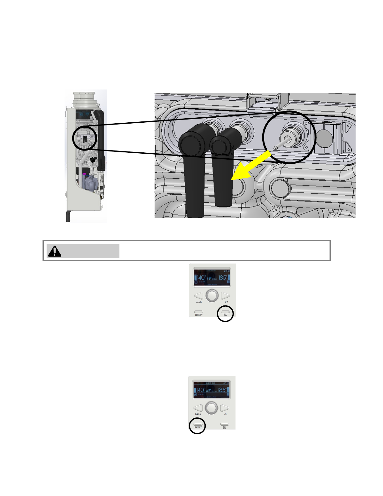
Rinnai M-Series Condensing Combi Boiler Installaon and Operaon Manual 51
Test the Ignion Safety Shut O Device
Do not touch the inside of the wiring connecon while it is disconnected.
WARNING
Remove the boiler front panel.
(See secon 3. About the Boiler → How to Remove the Front Panel for detailed instrucons).
1
Disconnect the wiring connecon from the ame rod (located on le side of boiler).
2
Boiler le side
Remove the wiring connecon
On the control panel, press and hold the
Service Mode buon for approximately
7 seconds.
3
The boiler iniates one start-up aempt and four restart aempts.
Aer the last start-up aempt, the boiler locks out and the gas valve shuts o. Code 501 No Flame Detected
4
Reconnect the wiring connecon to the ame rod. Be careful not to touch the inside of the wiring connecon.
5
Press the RESET buon on the control panel.
6
The boiler should start up. If the boiler does not start up, contact Rinnai Customer Care at 1-800-621-9419.
7
Replace the boiler front panel.
8
Page 52
52 Rinnai M-Series Condensing Combi Boiler Installaon and Operaon Manual
• Do not use an extension cord or adapter plug
with this appliance.
• The boiler must be electrically grounded in
accordance with local codes and ordinances or,
in the absence of local codes, in accordance with
the Naonal Electrical Code, ANSI/NFPA No. 70.
WARNING
Power Supply
8
Guidelines
When connecng the power supply, follow these
guidelines:
• If using the 6.5 FT (2 m) power cord (supplied
with boiler), plug it into a standard three-prong
120 VAC, 60 Hz properly grounded wall outlet.
• The boiler requires 120 VAC, 60 Hz power from a
properly grounded circuit.
• Do not rely on the gas or water piping to ground
the boiler. Ground locaons are provided inside
the boiler.
• The wiring diagram is located on the inside of the
boiler front cover.
• This boiler is supplied with 120 volts and is
equipped with a three-prong (grounding) plug for
your protecon against shock hazard. The plug
should be plugged directly into a properly
grounded three-prong receptacle. Do not cut or
remove the grounding terminal from this plug.
• Disconnect incoming power to the boiler by
removing the three-prong plug before:
− Performing repairs or installaon to internal
components or accessories
− Making wiring connecons and/or changes
to the wiring terminals on the boiler
No changes may be made to the wiring of the boiler.
• All connecons should be designed in
accordance with the applicable regulaons
• Label all wires prior to disconnecon when
servicing controls. Wiring errors can cause
improper and dangerous operaon
• Verify proper operaon aer operaon servicing.
CAUTION
CAUTION
Page 53
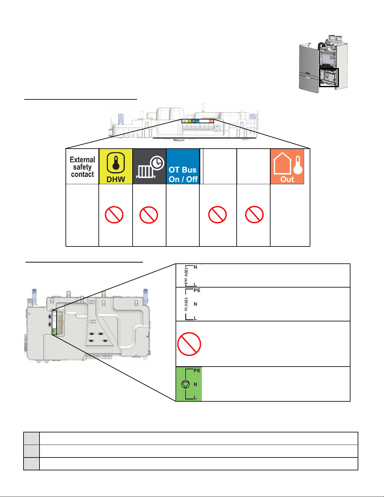
Rinnai M-Series Condensing Combi Boiler Installaon and Operaon Manual 53
Electrical Connecons
Devices such as the room thermostat and outdoor temperature sensor are connected to
the connecon terminal. The connecon terminals are located on the top and back of
the controller.
To access the controller, remove the front panel (see secon 3. About the Boiler → How
to Remove the Front Panel for detailed instrucons).
Controller Top Connecons
Addional 120 V input (Does not include ground
connecon)
120 V power supply to boiler
External pump input
DO NOT USE
This terminal is for Rinnai-use only and not for
use in any installaon
External
safety
contact
DO NOT
USE
Outdoor
temperature
sensor
DO NOT
USE
Room
thermostat
(On/O
thermostat or
control)
DO NOT
USE
For Rinnai
Use Only
For Rinnai
Use Only
For Rinnai
Use Only
DO NOT
USE
Not for
use in this
boiler
Controller Back Connecons
Controller
□
Conrm that the electricity is supplied from 120 VAC, 60 Hz power source and is in a properly grounded circuit.
□
Conrm that an extension cord or an adapter plug has NOT been used with the boiler.
□
Conrm connecon terminals are connected correctly.
Post-Power Supply Connecon Checklist
Page 54
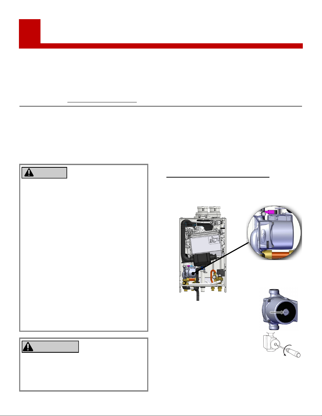
54 Rinnai M-Series Condensing Combi Boiler Installaon and Operaon Manual
Failure to properly commission the boiler as
described in this secon may result in unreliable and
unsafe burner operaon and reduced component
life.
WARNING
• Work on the boiler must be carried out by a
licensed professional, using correctly calibrated
instruments with current test cercaon. The
commissioning instrucons are intended for
licensed professionals who have the necessary
knowledge and are approved for working on
heang and gas systems.
• The boiler and its individual shut o valve must
be disconnected from the gas supply piping
system during any pressure tesng of that system
at test pressures in excess of 1/2 PSI (3.5kPa).
• Before the boiler is red for the rst me:
− Ensure the boiler and system are fully de-
aerated
− Purge the gas line between the gas meter
and the boiler
− Prime the pump (as described in this secon)
NOTICE
1. Remove the boiler front cover. See secon “How to
Remove the Front Panel” for complete instrucons.
2. Locate the vent pump.
Boiler commissioning is a procedure used aer boiler
installaon to ensure the system and boiler were
installed correctly and ready for operaon.
Commissioning
9
Instrucons
Step 1: Prime the Pump
Safety Precauons
You Will Need:
• Philips head screwdriver
• Flat head screwdriver
• Combuson analyzer (calibrated)
3. Remove the vent pump screw.
Pump
4. Use a at head screwdriver to
ensure the impeller spins freely.
5. When the impeller spins freely and water exits
though the vent port, the pump is ready for
operaon.
6. Replace the vent pump screw.
7. Proceed to the next step.
THIS SECTION IS INTENDED FOR THE INSTALLER
This boiler must be commissioned by a licensed professional. Installer qualicaons: A trained and qualied
professional must install the appliance, inspect it, and leak test the boiler before use. The warranty will be voided due
to any improper installaon. The trained and qualied professional should have skills such as: Gas sizing; Connecng
gas lines, water lines, valves, and electricity; Knowledge of applicable naonal, state, and local codes; Installing venng
through a wall or roof; and training in installaon of condensing boilers. Training for Rinnai Condensing Boilers is
accessible online at www.trainingevents.rinnai.us.
Page 55
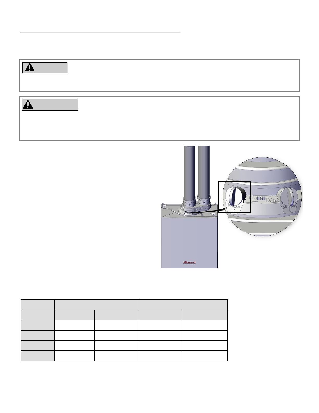
Rinnai M-Series Condensing Combi Boiler Installaon and Operaon Manual 55
1. Put the boiler into operaon with a maximum DHW
or heat demand.
2. From the controller home screen, press and hold the
Chimney Acve buon for approximately 7 seconds.
3. Remove the plug covering the ue gas test port and
place the calibrated combuson analyzer probe into
the port (see right image).
4. Scroll to ON and press OK.
5. Scroll to 100% and press OK.
6. The boiler is now at maximum input.
7. Aer the boiler has run for approximately one
minute, the O2 percentages displayed on the
combuson analyzer should match the ranges shown
in the table below.
If the ranges do not match, adjust the parameters by
following the steps in the Adjust O2 Percentages
secon.
The O2 percentage seng is required to be checked at commissioning, maintenance and faults and adjusted if
needed.
NOTICE
The O2 percentage is required to be checked and adjusted aer a conversion from Natural Gas to Liquid Propane, or
from Liquid Propane to Natural Gas. Seng the O2 at maximum input must be performed with a calibrated
combuson analyzer that is set to the correct gas type.
WARNING
Table: Nominal O2 Percentages
Step 2: Set the O2 at Maximum Input
THIS SECTION IS INTENDED FOR THE INSTALLER
MAXIMUM INPUT MINIMUM INPUT
Model Natural Gas Liquid Propane Natural Gas Liquid Propane
M060C 4.7 - 4.9 5.0 - 5.2 6.3 - 6.5 6.6 - 6.8
M090C 4.2 - 4.4 5.0 - 5.2 5.8 - 6.0 6.6 - 6.8
M120C 4.2 - 4.4 5.0 - 5.2 5.8 - 6.0 6.6 - 6.8
M160C 4.2 - 4.4 5.0 - 5.2 5.8 - 6.0 6.6 - 6.8
Page 56
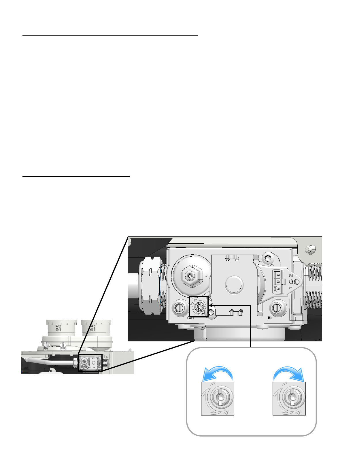
56 Rinnai M-Series Condensing Combi Boiler Installaon and Operaon Manual
Step 3: Set the O2 at Minimum Input
1. While sll in service mode (as described in the previous step), use the scroll wheel to adjust to 0%.
2. Press OK.
3. The boiler is now at minimum input.
4. Aer the boiler has run for approximately one minute, the O2 value displayed on the combuson analyzer should
be 1.6% higher than the maximum input value.
Example: If maximum input value is 4.8%, then minimum input value should be 6.4%.
If the values do not match, adjust the parameters by following the steps in the Adjust O2 Percentages secon.
5. When adjustments are complete, place the plug back into the ue gas test port.
6. On the controller, press and hold the Back buon unl the Home screen appears in the window.
This secon is required only if it is necessary to adjust O2 percentages.
Rotate the screw on the gas valve assembly unl you reach the levels shown in the Nominal O2 Percentages table (see
secon Step 2: Set the O2 at Maximum Input).
• Rotate counter-clockwise to decrease the O2 percentage
• Rotate clockwise to increase the O2 percentage
Adjust O2 Percentages
INCREASE O2
DECREASE O2
Counter-
Clockwise
Clockwise
THIS SECTION IS INTENDED FOR THE INSTALLER
Page 57
Rinnai M-Series Condensing Combi Boiler Installaon and Operaon Manual 57
Complete the following checklist when boiler installaon is complete. You should be able to answer YES to each
queson. If you answer NO, installaon is not complete. Refer to the applicable secon in the Rinnai M-Series
Condensing Boiler Installaon and Operaon Manual for addional informaon.
For assistance, contact your local dealer or distributor, or call Rinnai Customer Care at 1-800-621-9419.
INSTALLATION LOCATION YES NO
Have you veried the unit, vent and air intakes meet the clearance requirements?
VENTING YES NO
Have all corrosive compounds been removed from around the combuson air inlet of the boiler?
Have you followed the combuson air requirements to provide sucient combuson air for the boiler?
Are the correct venng products for the installed model being ulized?
Have you installed the vent screen(s) for Schedule 40 PVC/CPVC vent applicaons if applicable?
Have you veried the vent system does not exceed maximum length?
SYSTEM PIPING YES NO
Have the water lines been purged of all debris and the lter cleaned?
Have you veried the hot and cold water lines to the boiler are not interchanged?
Does the water supply to the boiler have adequate pressure? Is it free of chemicals? Did you verify it does
not exceed total hardness that will damage the heat exchanger?
Have you veried that no toxic chemicals were introduced to the potable water?
Did you drain the boiler if not intended to be used immediately?
Have water quality issues (if any) been addressed?
Have you performed the leak and pressure test for the boiler and plumbing system?
Are the isolaon valves installed? (for DHW systems only)
CONDENSATE DRAIN YES NO
If the condensate pump is installed, is it wired to deacvate the boiler in the event of failure?
Did you verify the condensate drain pipe is as short as possible and has a downward pitch toward the drain
or condensate pump?
Is all condensate drained and disposed of as per local codes?
Did you use ONLY corrosion resistant materials for the condensate drain lines?
Did you verify the condensate drain pipe along its enre length is at least the same diameter as the drain
line?
Did you check to ensure the condensaon drain lines are protected from freezing?
Have you veried the condensate drain line is not plumbed with the pressure relief valve?
Have you conrmed the condensate drain line is not connected with an air condioning evaporator coil
drain?
This boiler has an integrated condensate trap. Have you veried that an external condensate trap is not
installed?
Have you conrmed the end of the condensate drain pipe is open to atmosphere?
Post-Installation Checklist
10
Page 58
58 Rinnai M-Series Condensing Combi Boiler Installaon and Operaon Manual
GAS SUPPLY YES NO
Did you verify the gas system is appropriately sized?
Did you verify the boiler is rated for the gas type supplied?
Have you performed a gas line and connecon leak test?
Did you install a manual gas control valve in the gas line to the boiler?
Is the inlet gas pressure within limits?
Did you purge the gas line of any debris before connecng the boiler?
PRESSURE RELIEF VALVE (PRV) YES NO
Does the PRV comply with the standard for Relief Valves and Automac Gas Shuto Devices for Hot Water
Supply Systems ANSI Z21.22, and/or the standard Temperature, Pressure, Temperature and Pressure Relief
Valves and Vacuum Relief Valves, CAN1-4.4?
Did you verify the DHW PRV is rated up to 150 psi and (at least) the maximum BTU/hr of the boiler and the
heang system PRV rated to 30 PSI?
Is the discharge from the PRV piped to the ground or into a drain system as per local codes?
Is the discharge line from the PRV pitched downward and does it terminate 6 in. (152 mm) above the drains?
Is the discharge end of the line plain (unthreaded) and a minimum of 3/4 in. diameter?
Is the discharge line material suitable for at least 180° F water?
Did you take measures to protect the PRV and PRV discharge line from freezing?
Have you veried the PRV is not plumbed with the condensate drain line?
Have you veried the PRV is not plugged and that reducing ngs, valves, or other restricons are not
installed in the relief line?
POWER SUPPLY YES NO
Conrm that the electricity is supplied from 120 VAC, 60 Hz power source and is in a properly grounded circuit.
Conrm that an extension cord or an adapter plug has NOT been used with the boiler.
COMMISSIONING YES NO
Did you prime the pump?
Did you set the boiler O2 at maximum input?
Did you set the boiler O2 at minimum input?
Page 59
Rinnai M-Series Condensing Combi Boiler Installaon and Operaon Manual 59
Operation
11
Topics in this secon
• Start-Up Informaon
• Control Panel
• Boiler Display
• Basic Operaon Sengs
This secon includes instrucons for starng and operang the boiler.
Start-Up Informaon
The boiler will not immediately re up and begin operaon. The boiler will go into an automac de-aeraon program
that is approximately 7 minutes in duraon.
NOTICE
It can take up to a week before all the air has disappeared from a newly lled and pressurized installaon. During the
rst week of operaon, noises can be heard which indicate the presence of air. The automac air vent in the boiler
will remove the air, which means the water pressure will reduce some during this period and therefore addional
water will be necessary to maintain proper pressure in the heang system.
Water Pressure Needed for Operaon
• The boiler is in normal operaon between 19 PSI and 43.5 PSI.
• Below 10.1 PSI, the boiler will have an error code (Fault 108 on the display) and be blocked from operaon.
Increasing the heang system water pressure will be necessary for operaon.
• Between 10 PSI and 19 PSI, operaon will be limited to 80% (Alert Warning 1P4 will appear on the display).
• Above 43.5 PSI, the boiler will have an error code (Fault 109 on the display) and be blocked from operaon as
the pressure is too high.
• The pressure relief valve supplied with the boiler is rated to 30 PSI.
NOTICE
Page 60
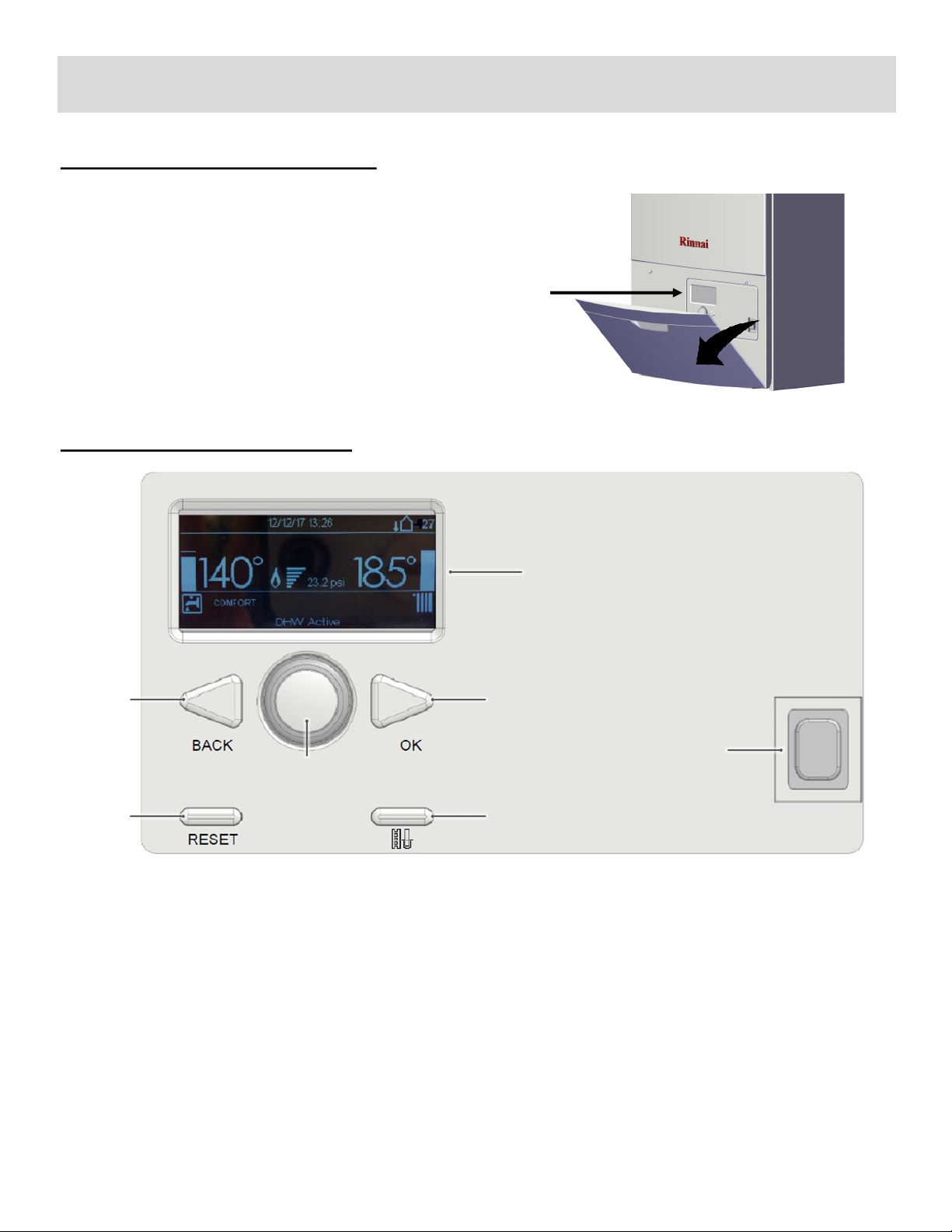
60 Rinnai M-Series Condensing Combi Boiler Installaon and Operaon Manual
Control Panel
Power (On/O)
Press to turn the boiler on
or o. (I = On O = O)
Selector Wheel
Turn the wheel le or right
to scroll through available
menu opons
Back
Press to go back one screen.
Reset
Press to reset a fault code.
See Reset Fault Code secon
(in this secon) for more
informaon
OK
Press to select an item.
Chimney Acve (Service Mode)
Press to enter into service mode which
allows adjustment of high re/low re and
O2 sengs.
See Chimney Acve (Service Mode) secon
(in this secon) for more informaon
Boiler Display
Displays boiler status informaon.
See Boiler Display secon (next
secon) for more informaon
❶
❷
❸
❹
❺
❻
❼
❶
❷
❸
❹
❺
❻
❼
Access the Control Panel
Slowly lower the protecve panel on the front cover to access the
control panel.
Control
panel
Control Panel Features
I
O
Page 61
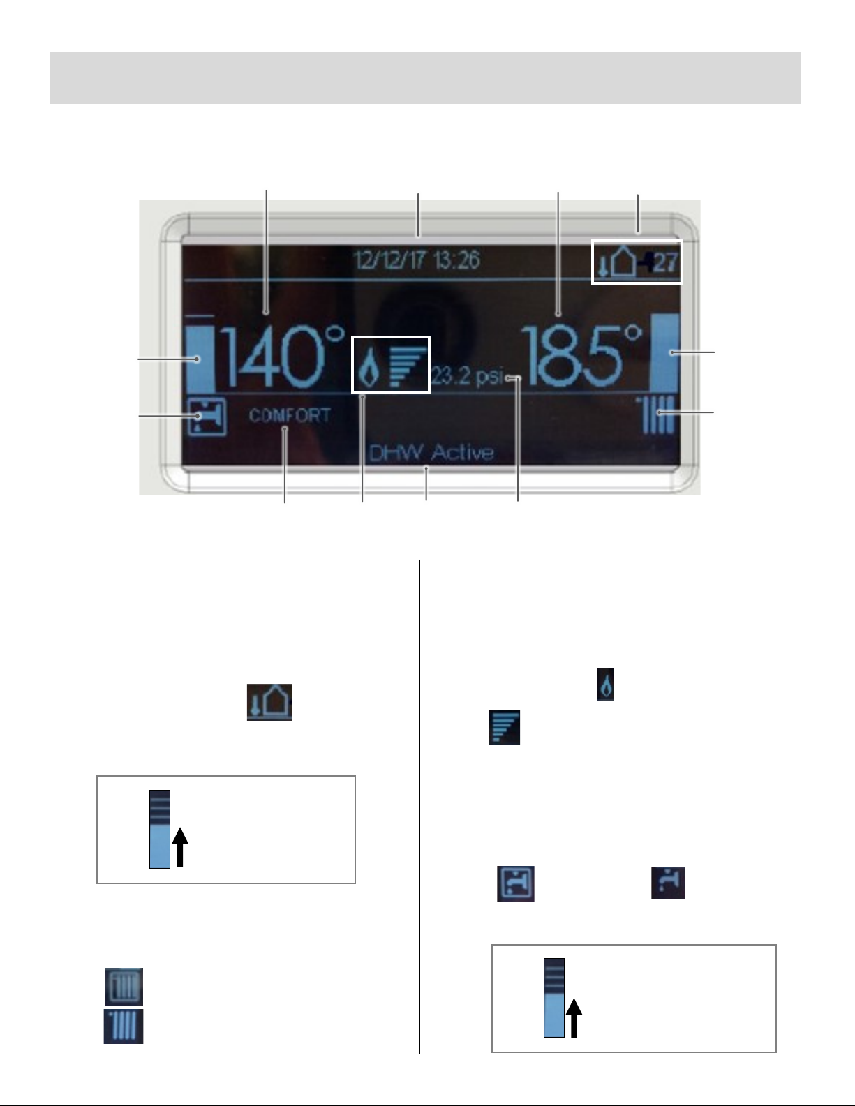
Rinnai M-Series Condensing Combi Boiler Installaon and Operaon Manual 61
Boiler Display
Heang supply setpoint
DHW setpoint temperature
DHW status symbol
A box around the faucet symbol indicates
DHW is in operaon
DHW comfort or economy mode is acve
Boiler status indicator, such as DHW is acve,
Central Heang is acve, error messages, and
other status informaon
Fire level status
Scale rises as the
temperature increases
HOT
COOL
Visual illustraon of current central
heang temperature
❶
❷
❸
❹
❺
❻
❼
❽
❾
❿
⓫
⓬
❶
❷
❸
❹
❺
❻
Central heang status symbol
A box around the radiator symbol indicates
central heang is in operaon
❼
❽
❾
❿
⓫
⓬
Current date and me
Outdoor temperature
Current central heang system water pressure
High re (maximum of six bars)
Low re
DHW
IN OPERATION
Visual illustraon of current hot water temperature
Scale rises as the hot water
temperature increases
HOT
COOL
DHW NOT
IN OPERATION
CENTRAL HEATING IN OPERATION
CENTRAL HEATING NOT IN OPERATION
When the boiler is turned on, the main screen (also called the home screen) appears in the display.
Page 62
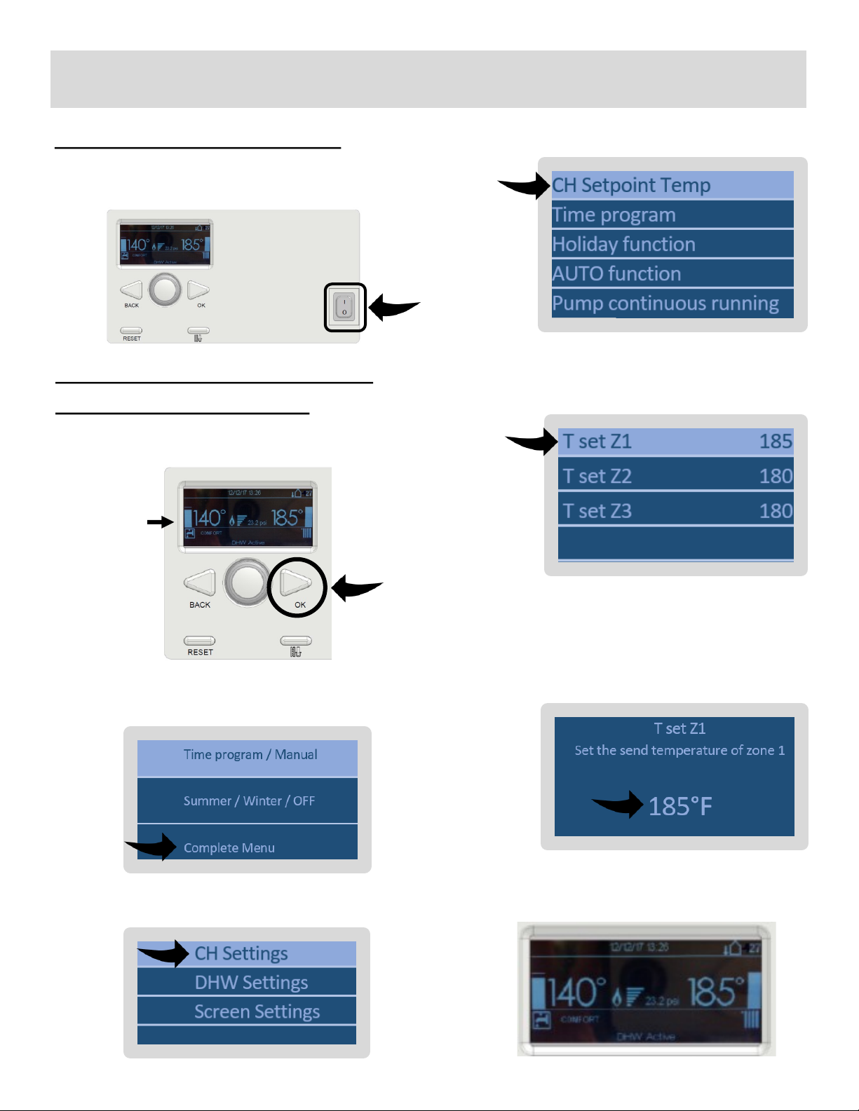
62 Rinnai M-Series Condensing Combi Boiler Installaon and Operaon Manual
To turn the boiler on or o, press the Power switch.
I = On O = O
Basic Operaon Sengs
Turn the Boiler On or O
Change the Central Heang
Setpoint Temperature
From the controller Home screen, press OK.
Turn the selector wheel to highlight Complete
Menu. Press OK.
CH Sengs is highlighted. Press OK.
CH Setpoint Temp is highlighted. Press OK.
The opon T set Z1 is highlighted. Press OK.
Note: T set Z2 and T set Z3 are inacve funcons.
Turn the selector wheel to unl the desired
temperature appears on the display. Press OK.
Available temperature sengs (minimum to
maximum): 68° F - 185° F (20° C - 85° C)
Press the Back buon unl the Home
screen appears on the display.
Home
screen
2
3
4
5
6
1
7
Page 63
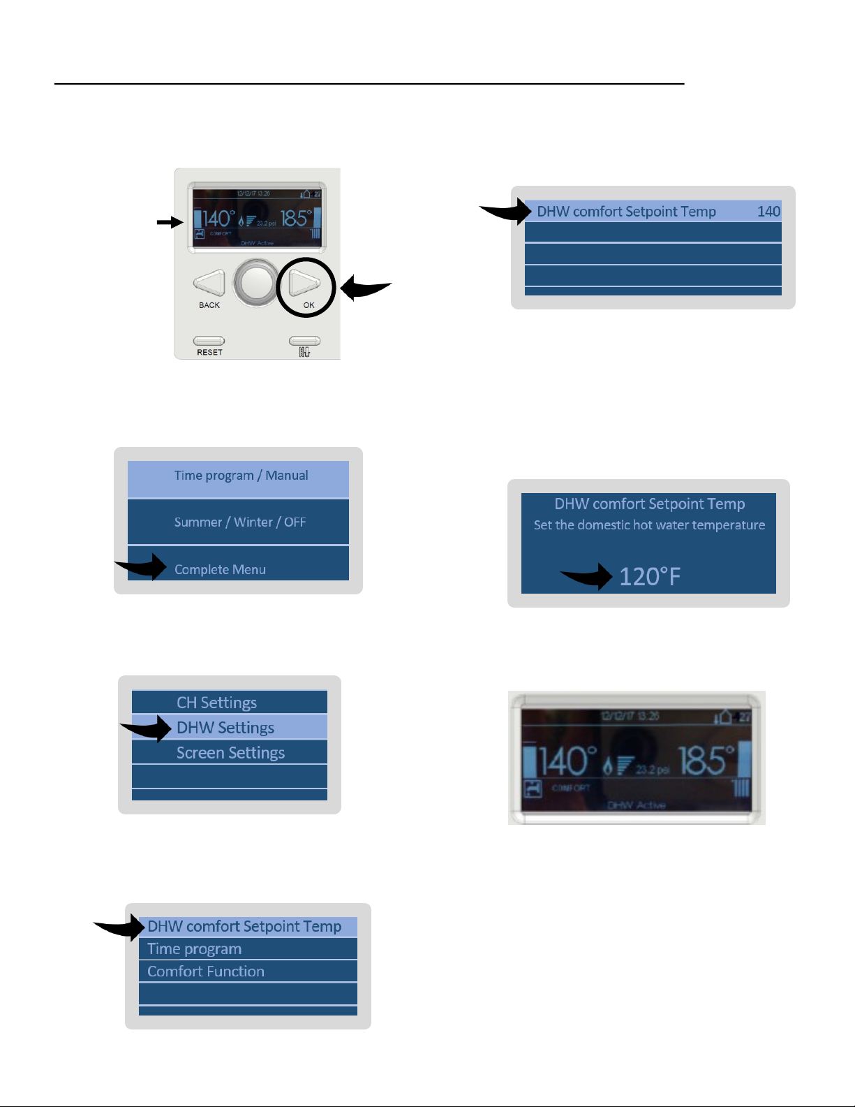
Rinnai M-Series Condensing Combi Boiler Installaon and Operaon Manual 63
Change the Domesc Hot Water Setpoint Temperature
Turn the selector wheel to unl the desired
temperature appears on the display.
Press OK.
Available temperature sengs:
(minimum - maximum)
104° F - 149° F (40° C - 65° C)
Press the Back buon unl the Home
screen appears on the display.
From the controller Home screen, press OK.
Turn the selector wheel to highlight
Complete Menu. Press OK.
Turn the selector wheel to highlight
DHW Sengs. Press OK.
Opon DHW Comfort Setpoint Temp is
highlighted. Press OK.
The current DHW comfort setpoint
temperature is displayed. Press OK.
Home
screen
2
3
4
5
6
1
7
Page 64
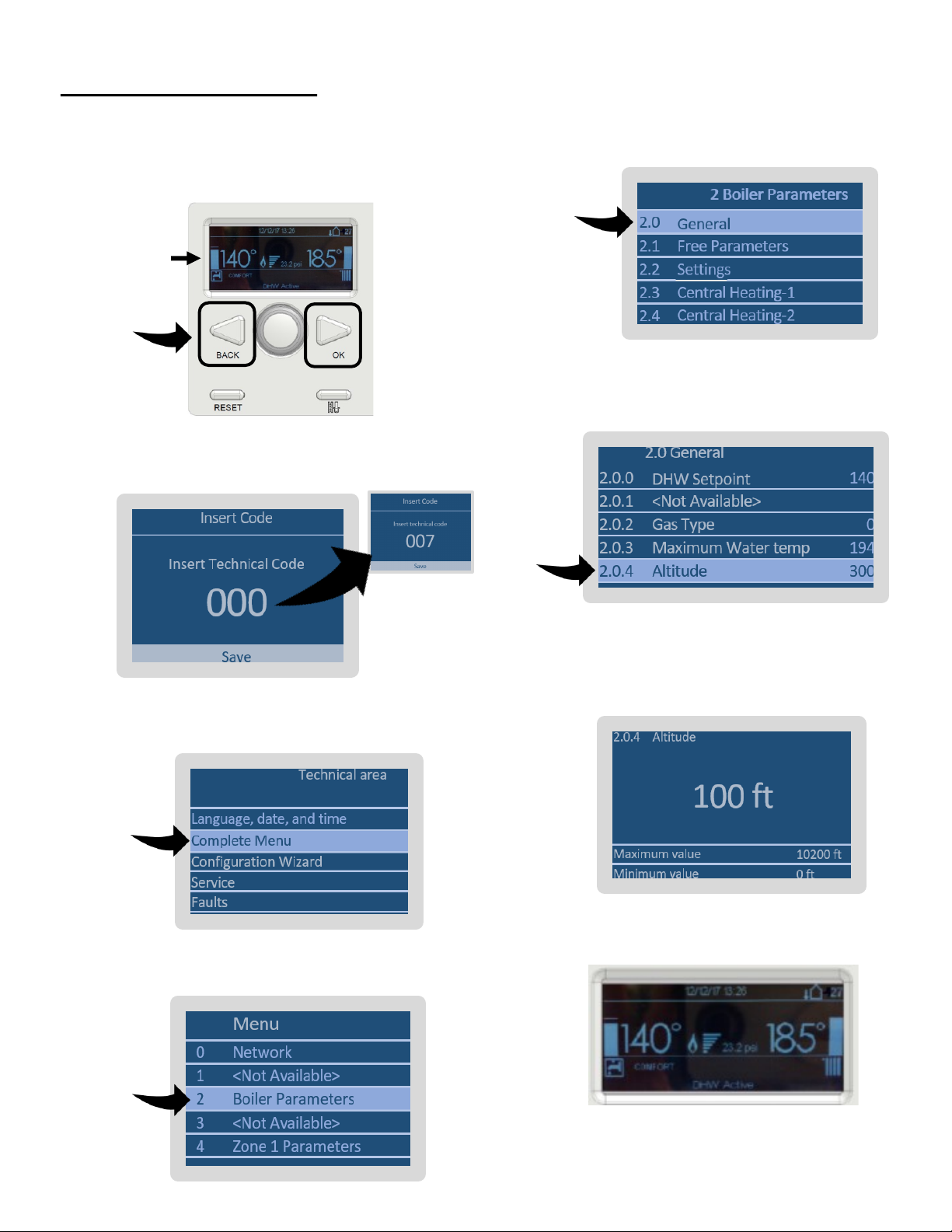
64 Rinnai M-Series Condensing Combi Boiler Installaon and Operaon Manual
Change the Altude
From the controller Home screen, press the
BACK and OK buons at the same me for 7
seconds.
Turn the selector wheel so that 007 appears
as the technical code.
Turn the selector wheel to highlight
Complete Menu. Press OK.
Turn the selector wheel to highlight
2 Boiler Parameters. Press OK.
Opon 2.0 General is highlighted. Press OK.
Turn the selector wheel to highlight
2.0.4 Altude. Press OK.
Press the Back buon unl the Home screen
appears on the display.
Scroll to the desired altude and press OK.
Note: Altude is displayed in Feet (FT)
measurements.
Home
screen
2
3
4
5
6
1
7
8
Page 65
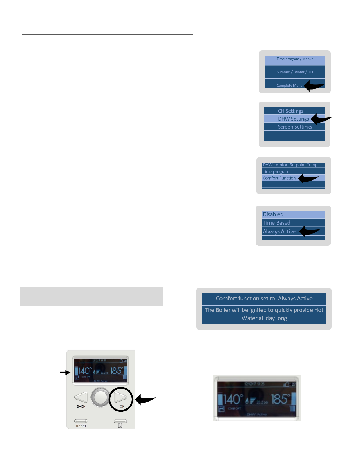
Rinnai M-Series Condensing Combi Boiler Installaon and Operaon Manual 65
6
Change DHW Comfort Mode Seng
Comfort mode is a domesc hot water seng that
enables the boiler to re up more oen to maintain
the heat exchanger temperature. This enables quicker
delivery of hot water to hot water xtures.
By default, comfort mode is disabled (turned o). To
enable (turn on) comfort mode, follow the steps
below.
Comfort mode has three opons:
Opon 1: Always Acve
This opon provides connuous hot water all day
long. The boiler maintains the primary heat exchanger
temperature to quickly deliver hot water to the plate
heat exchanger. This selecon provides the quickest
delivery of hot water to hot water xtures, but uses
the most energy.
Opon 2: Time Based
The boiler maintains the primary heat exchanger
temperature based o of me selecons. This
selecon requires more energy use than when
disabled, but not as much energy use as the “Always
Acve” opon.
Opon 3: Disabled
The boiler operates and produces hot water; however,
it will not maintain the primary heat exchanger
temperature for quicker hot water producon. This
selecon saves some energy, but requires longer me
to provide hot water to the hot water xtures.
Always Acve
To enable the Always Acve comfort mode seng,
follow the steps below.
4
5
From the controller Home screen, press OK.
Turn the selector
wheel to highlight
Complete Menu.
Press OK.
Home
screen
2
1
Turn the selector
wheel to highlight
DHW Sengs.
Press OK.
3
Turn the selector
wheel to highlight
Comfort Funcon.
Press OK.
Turn the selector
wheel to highlight
Always Acve.
Press OK.
Turn the selector wheel to highlight
Always Acve. Press OK.
The message below appears.
7
The Always Acve comfort mode is selected.
To exit, press the Back buon unl the Home
screen appears on the display.
Page 66
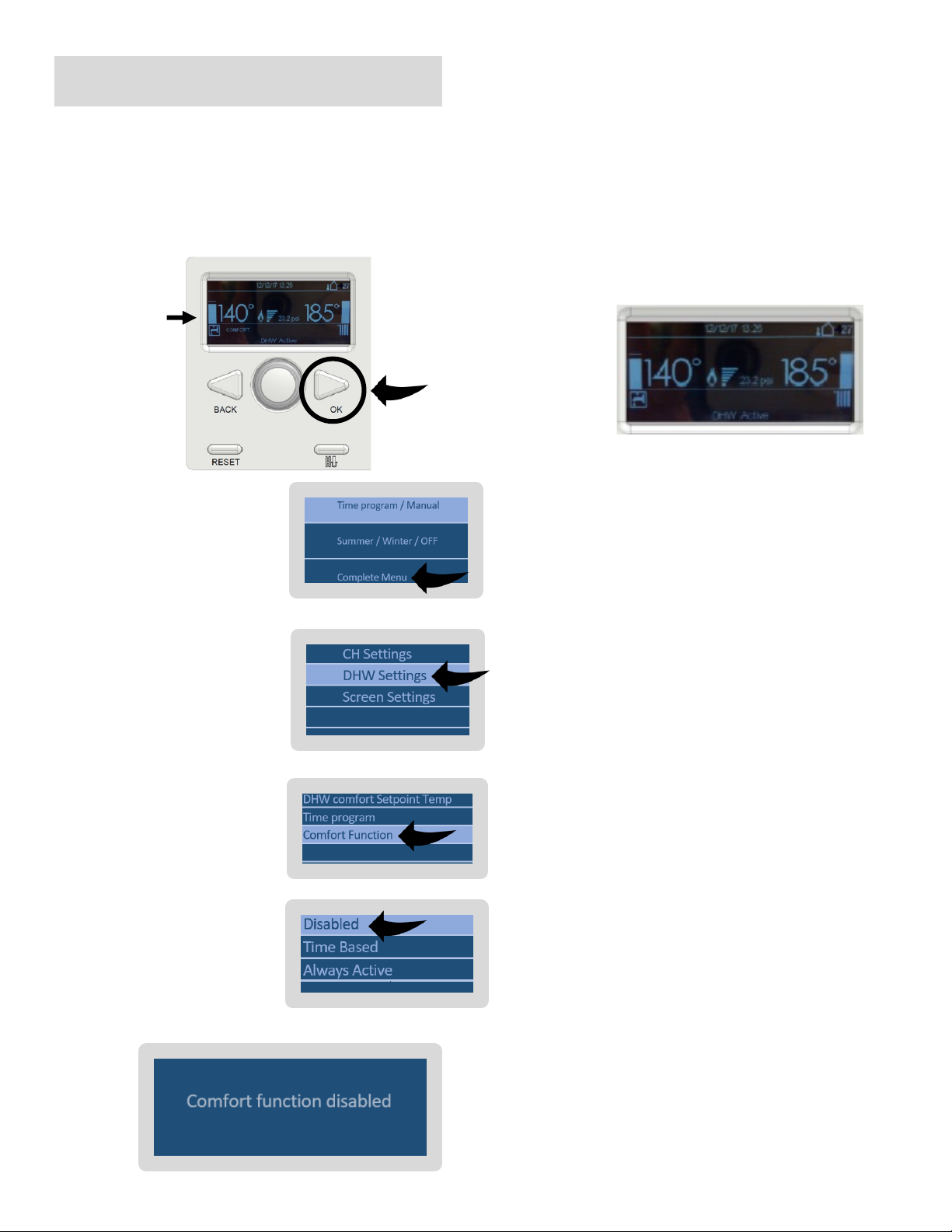
66 Rinnai M-Series Condensing Combi Boiler Installaon and Operaon Manual
6
Disabled
To disable Comfort mode, follow the steps below.
4
5
From the controller Home screen, press OK.
Turn the selector
wheel to highlight
Complete Menu.
Press OK.
Home
screen
2
1
Turn the selector
wheel to highlight
DHW Sengs.
Press OK.
3
Turn the selector
wheel to highlight
Comfort Funcon.
Press OK.
Disabled is selected
Press OK.
Comfort mode is disabled.
To exit, press the Back buon unl the Home
screen appears on the display.
The message below appears.
Page 67
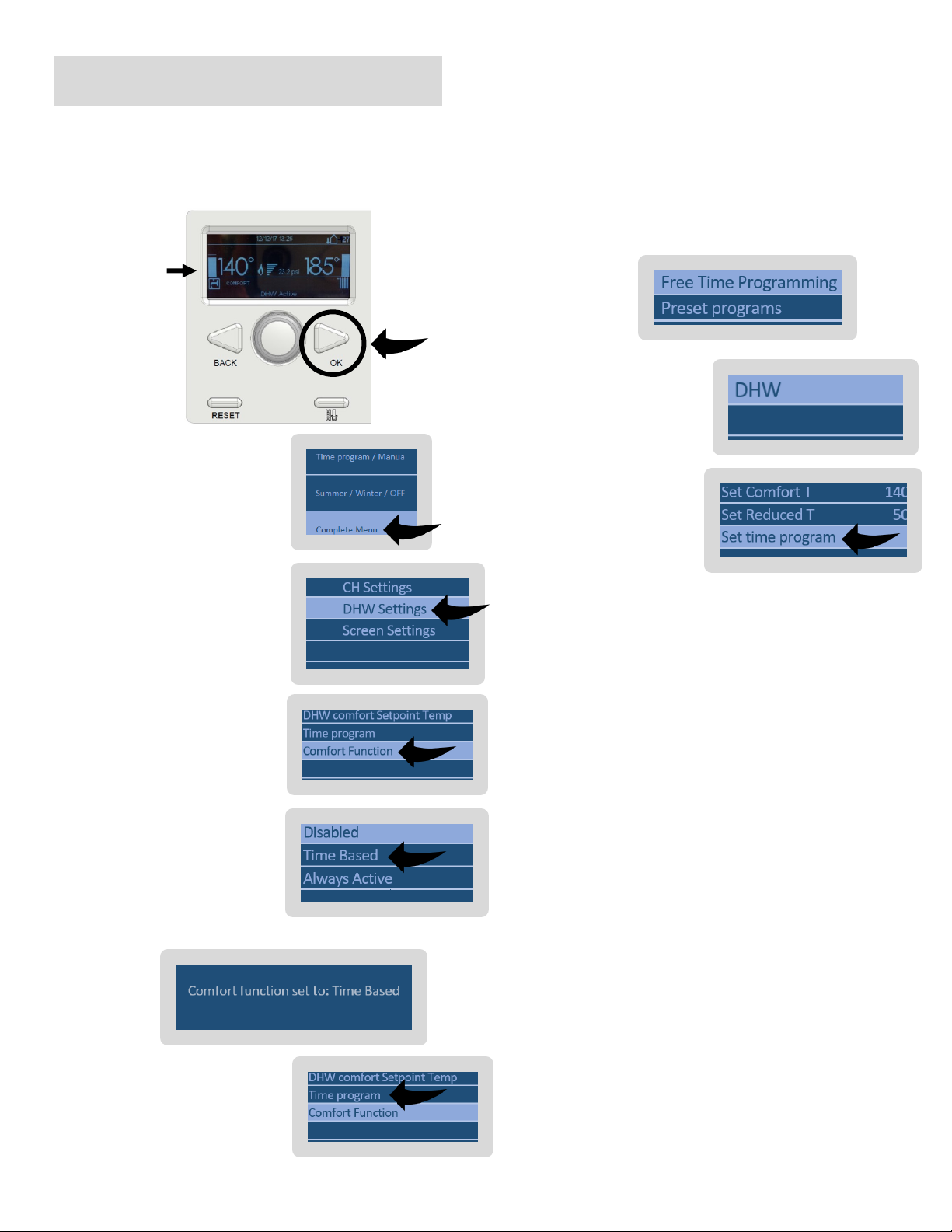
Rinnai M-Series Condensing Combi Boiler Installaon and Operaon Manual 67
Time Based
4
5
From the controller Home screen, press OK.
Turn the selector
wheel to highlight
Complete Menu.
Press OK.
Home
screen
2
1
Turn the selector
wheel to highlight
DHW Sengs.
Press OK.
3
Turn the selector
wheel to highlight
Comfort Funcon.
Press OK.
Turn the selector
wheel to highlight
Time Based.
Press OK.
The message below appears.
To enable the Time Based comfort mode seng,
follow the steps below.
7
8
6
Press the Back buon
one me. The
following screen
appears.
Select Time program.
Select one of the two opons:
• Free Time Programming—user-dened
mes for when comfort mode is acve
• Preset programs—opons for preset
mes for comfort mode to be acve
DHW is selected.
Press OK.
9
Turn the
selector wheel
to highlight Set
me program.
Press OK.
10
You then select the days with the same
me program. Use the selector wheel to
scroll to the day(s) you want the same.
Select "OK" on each day that will have
the same schedule.
Page 68
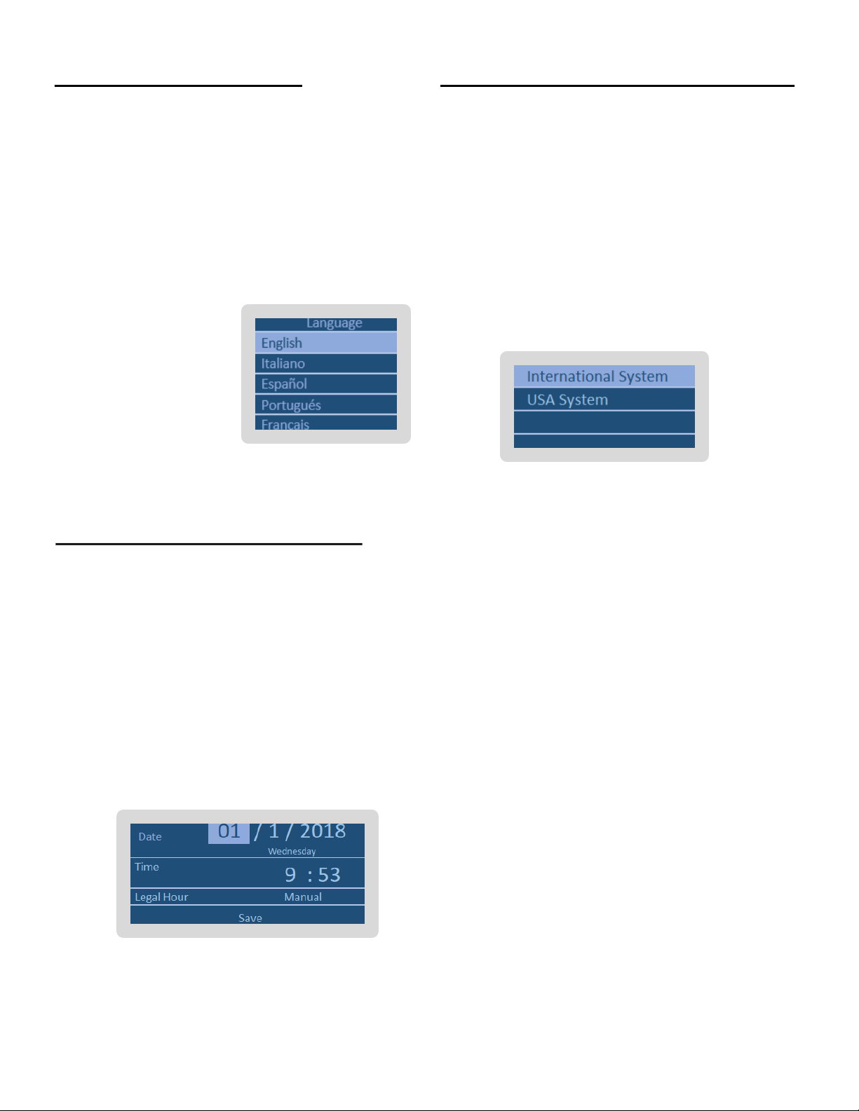
68 Rinnai M-Series Condensing Combi Boiler Installaon and Operaon Manual
Change the Language
To change the language appearing on the boiler
display, follow the steps below.
1. From the controller Home screen, press OK.
2. Turn the selector wheel to highlight Complete
Menu. Press OK.
3. Turn the selector wheel to highlight Screen
Sengs. Press OK.
4. Language is highlighted. Press OK.
5. Turn the selector wheel
to highlight the desired
language and press OK.
6. The language is
changed. To exit, press
the Back buon unl
the Home screen
appears on the display.
Change Units of Measurement
Change the Time and Date
To change the me and date appearing on the boiler
display, follow the steps below.
1. From the controller Home screen, press OK.
2. Turn the selector wheel to highlight Complete
Menu. Press OK.
3. Turn the selector wheel to highlight Screen
Sengs. Press OK.
4. Turn the selector wheel to highlight Time & Date.
Press OK.
5. Edit the following screen.
6. Press Save.
7. To exit, press the Back buon unl the Home
screen appears on the display.
To change the unit of measurements appearing on the
boiler display, follow the steps below.
1. From the controller Home screen, press OK.
2. Turn the selector wheel to highlight Complete
Menu. Press OK.
3. Turn the selector wheel to highlight Screen
Sengs. Press OK.
4. Turn the selector wheel to highlight System
measurement unit. Press OK.
5. Select Internaonal System or USA System.
6. Press Save.
7. To exit, press the Back buon unl the Home
screen appears on the display.
Page 69
Rinnai M-Series Condensing Combi Boiler Installaon and Operaon Manual 69
Some of the checks below should be performed by a licensed professional. Consumers
should never aempt any acon that they are not qualied to perform.
WARNING
Fault Codes
Code Descripon Reason(s)
Where Error is
Occurring
How to Resolve
101 Overheat
• The supply or return water
temperature is greater than 212° F
for 3 seconds.
• The return water temperature is
within 9° F of the supply
temperature for 24 hours
• The supply and return probe check
failed
Central Heang
operaon
Press the Reset buon
102 Pressure Sensor
Damaged
The pressure sensor has a short or
open circuit
Central Heang
operaon
Troubleshoot the
pressure sensor
103 Flow Check Failed 3
Times
Three ow checks failed within 15
minutes. 1P1 (Flow Check 1 Failed) was
the last error detected.
Central Heang
operaon
Press the Reset buon
104 Flow Check 2 Failed More than 27° F per second
change in supply or return water
temperature
Central Heang
operaon
Press the Reset buon
105 Flow Check Failed 3
Times
Three ow checks failed within 15
minutes. 1P3 (Flow Check 4 Failed) was
the last error detected.
Central Heang
operaon
Press the Reset buon
106 Flow Check Failed 3
Times
Three ow checks failed within 15
minutes. 1P4 (Filling Needed) was the
last error detected.
Central Heang
operaon
Press the Reset buon
107 Flow Check 5 Failed The return water temperature is more
than 63°F higher than the supply water
temperature and the burner is on
Central Heang
operaon
Press the Reset buon
108 Supply Pressure is below
Minimum Pressure
• The supply pressure is below
minimum pressure and the burner
is on
• The burner is o with the supply
pressure below the minimum
pressure and deaeraon is acve
for 40 seconds
Central Heang
operaon
Raise the supply
pressure above the
minimum pressure
109 Supply Pressure is above
Maximum Pressure
The supply pressure is above the
maximum pressure
Central Heang
operaon
Lower the pressure to
4.3 PSI below the
maximum supply
pressure
110 Send Probe Damaged
The supply sensor has a short or open
circuit
Central Heang
operaon
Troubleshoot the
supply sensor
112 Return Probe Damaged
The return sensor has a short or open
circuit
Central Heang
operaon
Troubleshoot the return
sensor
114 Outdoor Probe Damaged
The outdoor sensor is installed and has
a short or open circuit
Central Heang
operaon
Troubleshoot the
outdoor sensor
When the boiler detects an error, a 3-digit blocking or fault code appears on the controller display.
• A blocking code is a temporary error that can be automacally corrected by the boiler.
• A fault code requires the error to be reset and/or corrected for the boiler to go back into a normal operang mode.
In the table below, fault codes are labeled with “Press the Reset buon” in the “How to Resolve” column.
An overview of the most common blocking and fault codes are listed below.
Page 70
70 Rinnai M-Series Condensing Combi Boiler Installaon and Operaon Manual
Code Descripon Reason(s) Fault Locaon How to Resolve
1P1 Flow Check 1 Failed
Change in supply temperature of 12.6°
F to 27° F in one second
Central Heang
operaon
The boiler will aempt
to correct for 10
seconds
1P2 Flow Check 3 Failed
The supply water temperature is more
than 99°F higher than the return water
temperature
Central Heang
operaon
The boiler will aempt
to correct for 10
seconds
1P3 Flow Check 4 Failed
The return water temperature is 18° F
higher than the supply water
temperature
Central Heang
operaon
The boiler will aempt
to correct for 10
seconds
1P4 Filling Needed
Supply pressure is below the warning
pressure
Central Heang
operaon
Raise the supply
pressure above the
minimum pressure
201
Combi Domesc Hot
Water NTC Damaged
The Domesc Hot Water sensor has a
short or open circuit
Domesc Hot
Water operaon
Troubleshoot the
Domesc Hot Water
sensor
203
Tank NTC Sensor
Damaged
The tank probe has a short or open
circuit
Domesc Hot
Water operaon
Troubleshoot the tank
probe
303 PCB Fault PC board soware or hardware error PC Board Press the Reset buon
304 Too Many Reset
The Reset buon was pressed more
than 5 mes in 15 minutes
PC Board
Wait for 15 minutes to
elapse without pressing
the Reset buon
306 PCB Fault PC Board error PC Board Press the Reset buon
309 Gas Relay Check Failed
Flame detected for 3 seconds aer the
gas valve closed
PC Board Press the Reset buon
3P9
Scheduled Maintenance-
Call Service
The maintenance mer has expired PC Board
Reset the monthly
mer for the next
maintenance interval
reminder
501 No Flame Detected Flame not detected
Flame ignion/
detecon
Press the Reset buon
502
Flame Detected with Gas
Valve Closed (False
Flame)
Flame detected before the gas valve
opened
Flame ignion/
detecon
Troubleshoot the ame
rod, igniter, electrode,
and gas valve
504 Flame Li Loss of ame during burner operaon
Flame ignion/
detecon
Press the Reset buon
5P1 1stIgnit Failed
Flame not detected during the rst
ignion aempt
Flame ignion/
detecon
Fault will go away at the
end of the second
ignion aempt
5P2 2ndIgnit Failed
Flame not detected during the second
ignion aempt
Flame ignion/
detecon
Fault will go away at the
end of the third ignion
aempt
5P3 Flame Li Loss of ame during burner operaon
Flame ignion/
detecon
Fault will go away with
proper ignion
612 Fan Error Fan speed is too high or too low Fan/Vent Press the Reset buon
1P9
Water Pressure Dynamic
Check
No pressure change aer 5 seconds of
running the pump
Central Heang
operaon
The boiler will check the
pressure for 30 seconds
and the error will go
away with proper inlet
pressure
140
Water Pressure Dynamic
Check
Two 1P9 water pressure checks failed
Central Heang
operaon
Press the Reset buon
Page 71
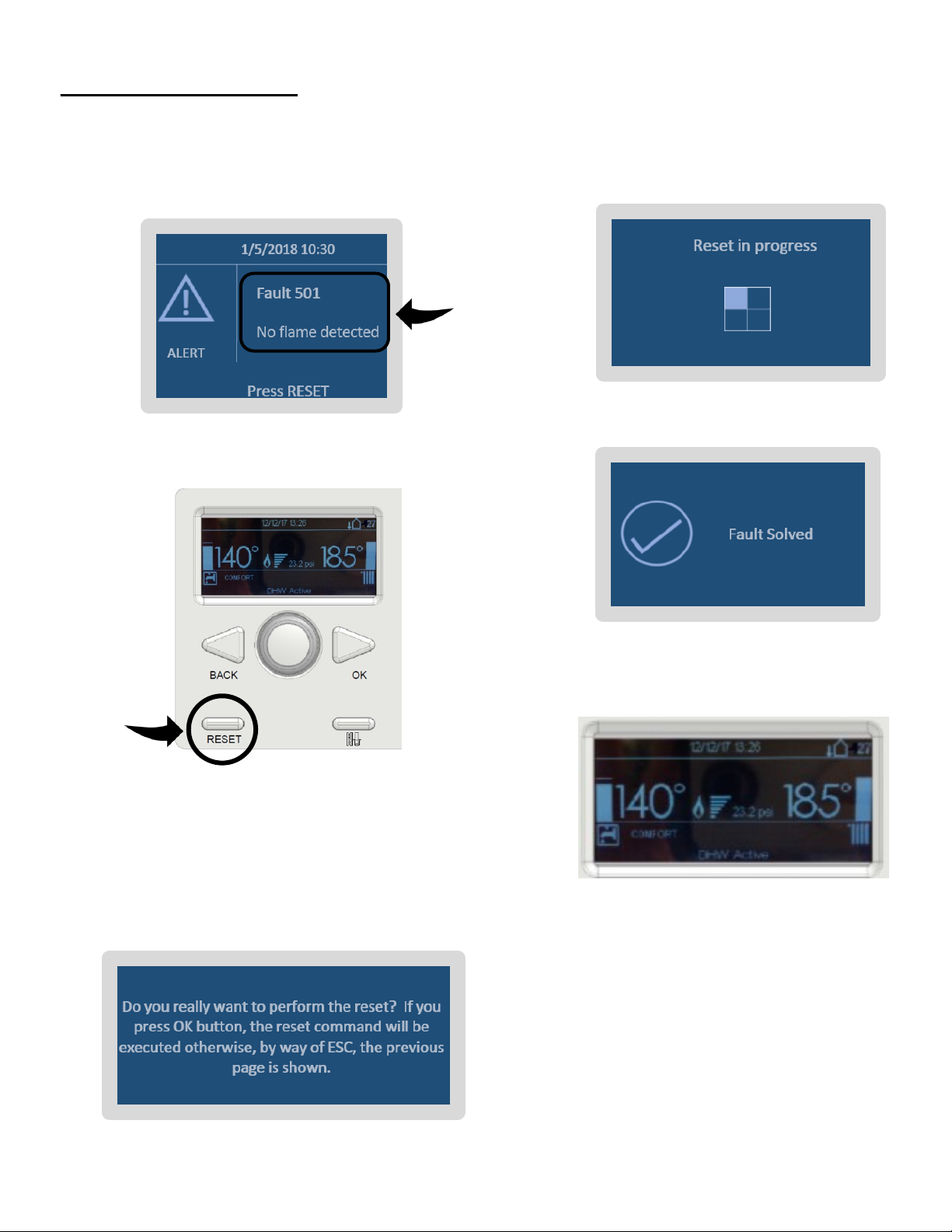
Rinnai M-Series Condensing Combi Boiler Installaon and Operaon Manual 71
Reset a Fault Code
When an error occurs, the fault code and
descripon appear on the display.
The following message appears:
Do you really want to perform the reset?
• Press OK to reset the error
• Press the ESC keyboard buon to cancel
reset and return to the previous screen
To reset the fault code, press the RESET buon.
The Reset in Progress message appears.
The Fault Solved message appears.
Aer the code is reset, the Home screen
automacally appears.
1
2
3
4
5
6
Page 72
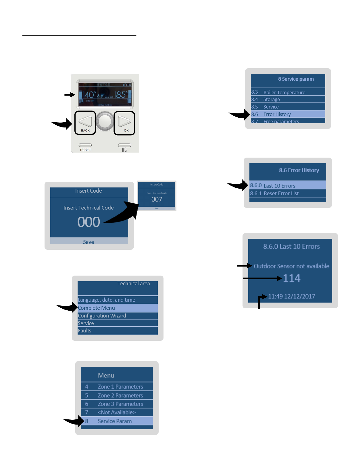
72 Rinnai M-Series Condensing Combi Boiler Installaon and Operaon Manual
View Error Code History
From the controller Home screen, press the
BACK and OK buons at the same me for
7 seconds.
Turn the selector wheel so that 007 appears
as the technical code.
Turn the selector wheel to highlight
Complete Menu. Press OK.
Turn the selector wheel to highlight
8 Service Param. Press OK.
Home
screen
2
3
4
1
5
Turn the selector wheel to highlight
8.6 Error History. Press OK.
6
Opon 8.6.0 Last 10 Errors is highlighted.
Press OK.
7
Scroll to view the last 10 errors.
Error
descripon
Error number
Time and date when
error occurred
Page 73
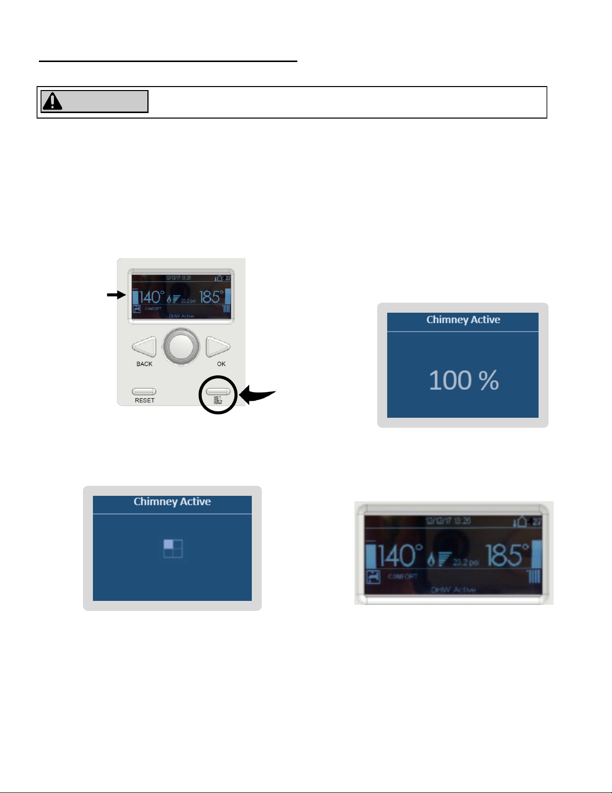
Rinnai M-Series Condensing Combi Boiler Installaon and Operaon Manual 73
Chimney Acve (Service Mode)
The Chimney Acve (service mode) buon puts the boiler into service mode which allows adjustment of high re/low
re and O2 sengs. To enter Chimney Acve (service mode):
From the controller Home screen,
press and hold the Chimney Acve
buon for approximately 7 seconds.
Chimney Acve (service mode) defaults to 100%.
Use the selector wheel to adjust between 0% to
100% and then press OK.
• 0% (boiler will run on low re/low load)
• 100% (boiler will run on maximum re/full load)
To exit Chimney Acve (service mode),
press the Back buon unl the Home
screen appears on the display.
The following screen appears indicang that
Chimney Acve (service mode) is acve.
This secon should be performed by a licensed professional. Consumers should never
aempt any acon that they are not qualied to perform.
WARNING
1
3
2
4
Home
screen
Page 74
74 Rinnai M-Series Condensing Combi Boiler Installaon and Operaon Manual
The following maintenance items are required for the
proper operaon of your boiler.
The appliance must be inspected annually by a licensed
professional. Repairs and maintenance shall be
performed by a licensed professional. The licensed
professional must verify proper operaon aer
servicing.
CLEANING
1. It is imperave that control compartments, burners,
and circulang air passageways of the appliance be
kept clean. Check burner ame for proper color.
Once ignited, the ame must cover the surface of
the burner.
To protect yourself from harm, before performing
maintenance:
• Turn o the electrical power supply by unplugging
the power cord or by turning o the electricity at
the circuit breaker. (The boiler controller does not
control the electrical power.)
• Turn o the gas at the manual gas control valve,
usually located immediately below the boiler.
• Turn o the incoming water supply. This can be
done at the isolaon valve immediately below the
boiler or by turning o the water supply to the
building.
WARNING
Keep the appliance area clear and free from
combusble materials, gasoline, and other ammable
vapors and liquids.
WARNING
This boiler must be inspected annually by a
licensed professional. Repairs and maintenance shall be
performed by a licensed professional. The licensed
professional must verify proper operaon aer servicing.
The ame must burn with a clear, blue, stable ame. If the
ame does not have this appearance, complete the following
steps:
1. Turn o and disconnect electrical power. Allow to cool.
2. Remove the front panel.
3. Use a vacuum to remove dust from the main burner and
fan blades. Do not use a wet cloth or spray cleaners on
the burner. Do not use volale substances such as benzene and thinners; they may ignite or fade the paint.
4. Use so dry cloth to wipe cabinet.
VENT SYSTEM
The vent system should be inspected at least annually for
blockages or damage. If the vent is blocked contact a
licensed professional.
If using a vent screen or room air lter, yearly inspect for
debris and blockages and clean if needed.
MOTORS
Motors are permanently lubricated and do not need periodic
lubricaon. However you must keep fan and motor free of
dust and dirt by cleaning annually.
BOILER CONTROLLER
Use a so damp cloth to clean the boiler controller. Do not
use solvents.
WATER QUALITY
Refer to the Water Quality Guidelines secon to determine
if your water needs to be treated or condioned. The water
must be potable, free of corrosive chemicals, sand, dirt, or
other contaminates. It is up to the installer to ensure the
water does not contain corrosive chemicals, or elements
that can aect or damage the heat exchanger. Water that
contains chemicals exceeding the levels required aect and
damage the heat exchanger. Replacement of the heat
exchanger due to water quality damage is not covered by
the warranty.
SNOW ACCUMULATION
• Keep the area around ue terminal free of snow and ice.
The boiler will not funcon properly if the combuson
air or exhaust vent pipes are impeded (blocked or
parally blocked) by obstrucons.
• Keep the condensate drain line free of snow and ice.
Ensure the line is not blocked or clogged and that
condensate is owing freely.
COASTAL INSTALLATIONS
Installaons located in or near coastal areas may require
addional maintenance due to corrosive airborne ocean salt.
If corrosion is observed on the body of the boiler, the boiler
shall be inspected to ensure proper operaon and if
necessary, repaired or replaced.
Maintenance
12
Boiler Maintenance
Topics in this secon
• Boiler Maintenance
• Flushing the Plumbing System for
Central Heang Systems
Page 75
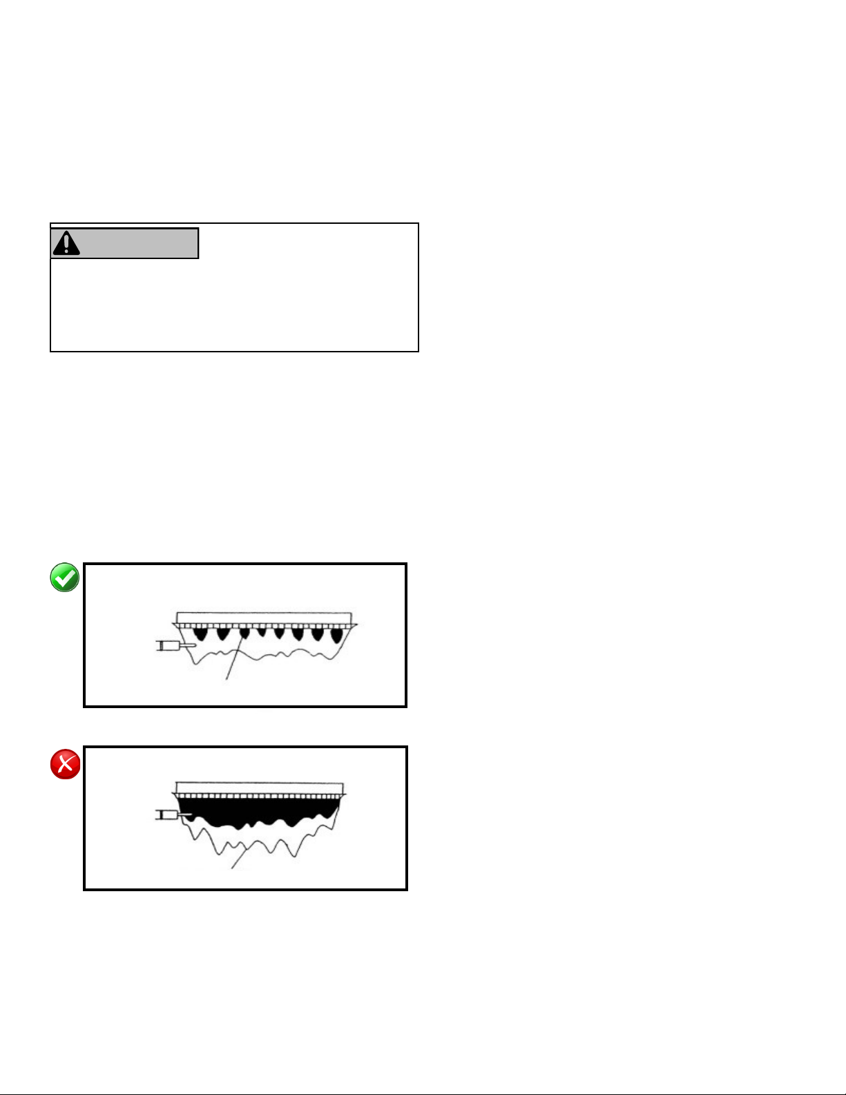
Rinnai M-Series Condensing Combi Boiler Installaon and Operaon Manual 75
Tesng the pressure relief valve should only be
performed by a licensed professional. Water discharged
from the pressure relief valve could cause severe burns
instantly or death from scalds.
WARNING
PRESSURE RELIEF VALVE
Operate the pressure relief valve manually once a year. In
doing so, it will be necessary to take precauons with
regard to the discharge of potenally scalding hot water
under pressure. Ensure discharge has a safe place to ow.
Contact with your body or other property may cause
damage or harm.
FREEZE PROTECTION
Freeze protecon for new or exisng systems must use
glycol that is specially formulated for this purpose. This
includes inhibitors, which prevent the glycol from
aacking the metallic components. The glycol should be
for mul-metallic components. For a list of approved
system cleaners, inhibitors, and anfreezes, refer to
secon 13. Appendices > Approved Cleaners, Inhibitors
and Anfreezes.
Make certain to check that the system uid is correct for
the glycol concentraon and inhibitor level. The system
should be tested at least once a year and as
recommended by the producer of the glycol soluon.
The allowed maximum concentraon is 50 percent.
VISUAL INSPECTION OF FLAME
Verify proper operaon aer servicing. The burner must
ame evenly over the enre surface when operang
correctly. The ame must burn with a clear, blue, stable
ame. See the parts breakdown of the burner for the
locaon of the view ports.
The ame paern should be as shown in the images
below:
SATISFACTORY FRONT VIEW
BLUE FLAME
FLAME ROD
YELLOW FLAME
FLAME ROD
UNSATISFACTORY
FRONT VIEW
When replacing an exisng boiler, the heang system
shall be ushed with an approved system cleaner before
the new boiler is added to the system. If the old boiler
has already been removed, a bypass must be piped in
when the new boiler is installed to facilitate the ushing
of the system.
The boiler must be isolated from the system while the
system is ushed. No system cleaner should ever enter
the boiler heat exchanger due to its causc nature
which could damage the heat exchanger.
Reference secon Approved Cleaners, Inhibitors and
Anfreezes in the Appendix for an approved list of sys-
tem cleaners, inhibitors, and anfreezes.
You Will Need
• Garden hose (Qty 3)
• 5-gallon bucket
• Approved system cleaner
• Circulang pump
Flushing the Plumbing
System for Central
Heang Systems
Page 76
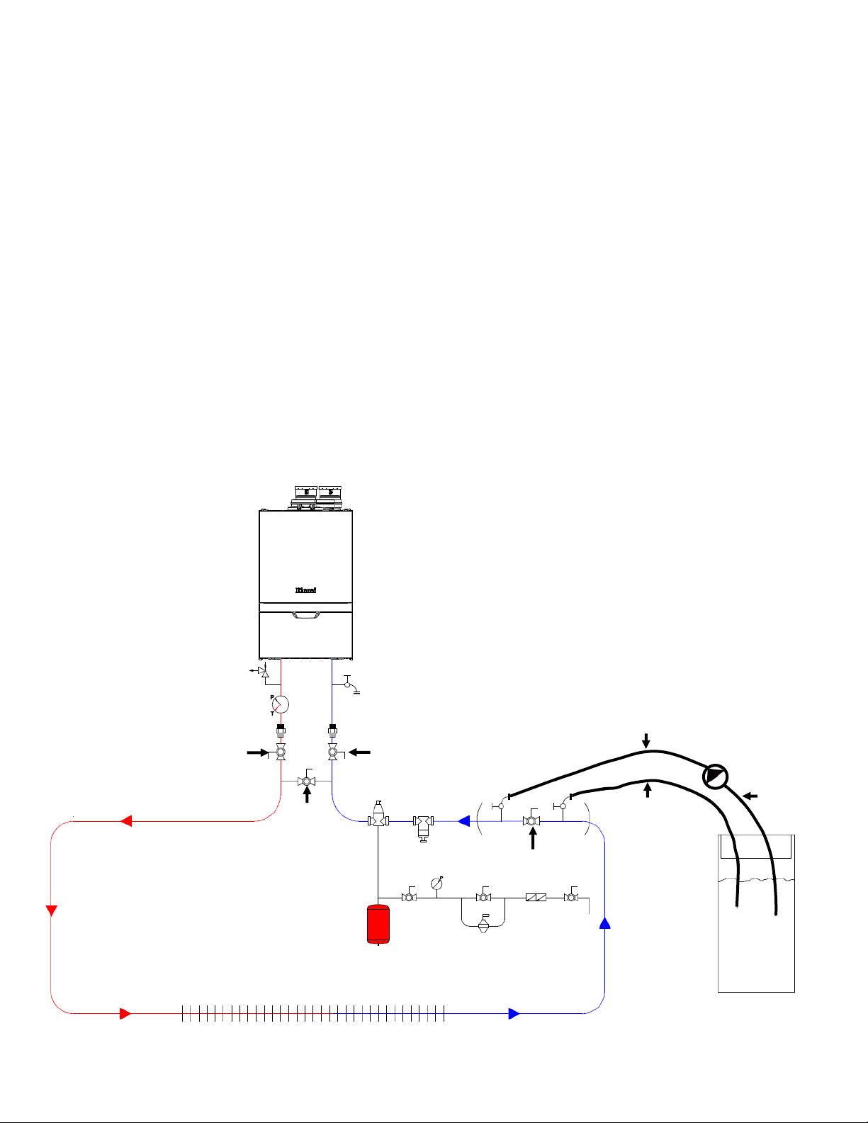
76 Rinnai M-Series Condensing Combi Boiler Installaon and Operaon Manual
Valve 2
System Return
System
Cleaner
System Supply
Hose 2
Hose 3
CP
Hose 1
Valve 4
Valve 1
Valve 3
P1
BD1 BD2
Instrucons
The following steps reference the image at the boom of the page.
1. If the installaon is a zone system (ulizes mulple zones), purge out each zone individually.
2. Close the automac ll valve on the system (F1).
3. Close the return side purge staon (BD2) and disconnect the hose (H3).
4. Open the main valve on the system return (V3).
5. Close the bypass valve below the boiler (V4).
6. Open the shuto valves on both the supply and return connecons below the boiler (V1 and V2).
7. Clean out the dirt trap per manufacture’s instrucons.
8. The boiler and system may now be lled through the ll valves.
Notes:
• Water should be within guidelines for water quality listed in the Water Quality Guidelines secon (4. Installaon
→ Choose an Installaon Locaon → Water Quality Guidelines)
• Use the proper water treatment to ensure the pH and water hardness are within the Rinnai boiler water quality
guidelines listed in the Water Quality Guidelines secon (4. Installaon → Choose an Installaon Locaon →
Water Quality Guidelines)
• Test the pH of the water that will be used for lling the system.
Page 77

Rinnai M-Series Condensing Combi Boiler Installaon and Operaon Manual 77
Appendices
13
Approved Cleaners, Inhibitors and Anfreezes
Approved System Cleaners:
• Fernox F3 Cleaner
• Noble Noburst Hydronic System Cleaner
• Rhomar Hydro-Solv 9100
• Sennel X400
Approved System Inhibitors:
• Noble Noburst AL Inhibitor
• Rhomar Pro-tek 922
• Sennel X100
Approved System Anfreezes:
• Chem Frost 100%
• Fernox Alphi 11
• Hall-Chem Solar II
• Noble Noburst AL
• Rechochem Recofreeze AL
• Rhomar RhoGard Mutli-Metal (AL safe)
• Sennel X500
Below is a list of approved system cleaners, inhibitors, and anfreezes for use in hydronic plumbing systems ulizing
Rinnai boilers.
Topics in this secon
• Approved Cleaners, Inhibitors and
Anfreezes
• Boiler Parts
• System Applicaon Examples
• Gas Conversion
• Wiring Diagram
• Ladder Diagram
• Pressure Drop and Water Flow Curve
• Massachuses State Gas Regulaons
• Warranty
IMPORTANT
• System cleaners are not to be used in the boiler (use isolang valves at header assembly).
• The Rinnai boiler must be closed o (valved o) from the rest of the system, or not
connected, while cleaners are in the system.
• When cleaning is complete, drain the system and then ush with clean water to remove any
sediment.
Page 78
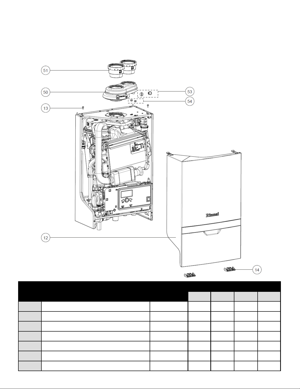
78 Rinnai M-Series Condensing Combi Boiler Installaon and Operaon Manual
Boiler Casing
Boiler Parts
Item # Descripon Part Number Quanty
M060C M090C M120C M160C
12 Front cover 809000145 1 1 1 1
13 Screw M5 x 12 mm 809000019 2 2 2 2
14 Hinge 809000146 2 2 2 2
50 2-pipe adapter 802000005 1 1 1 1
51 3 in. PVC adapter 802000006 2 2 2 2
53 Measurement port plug 808000024 1 1 1 1
54 Gas valve screw plug 809000148 1 1 1 1
Page 79
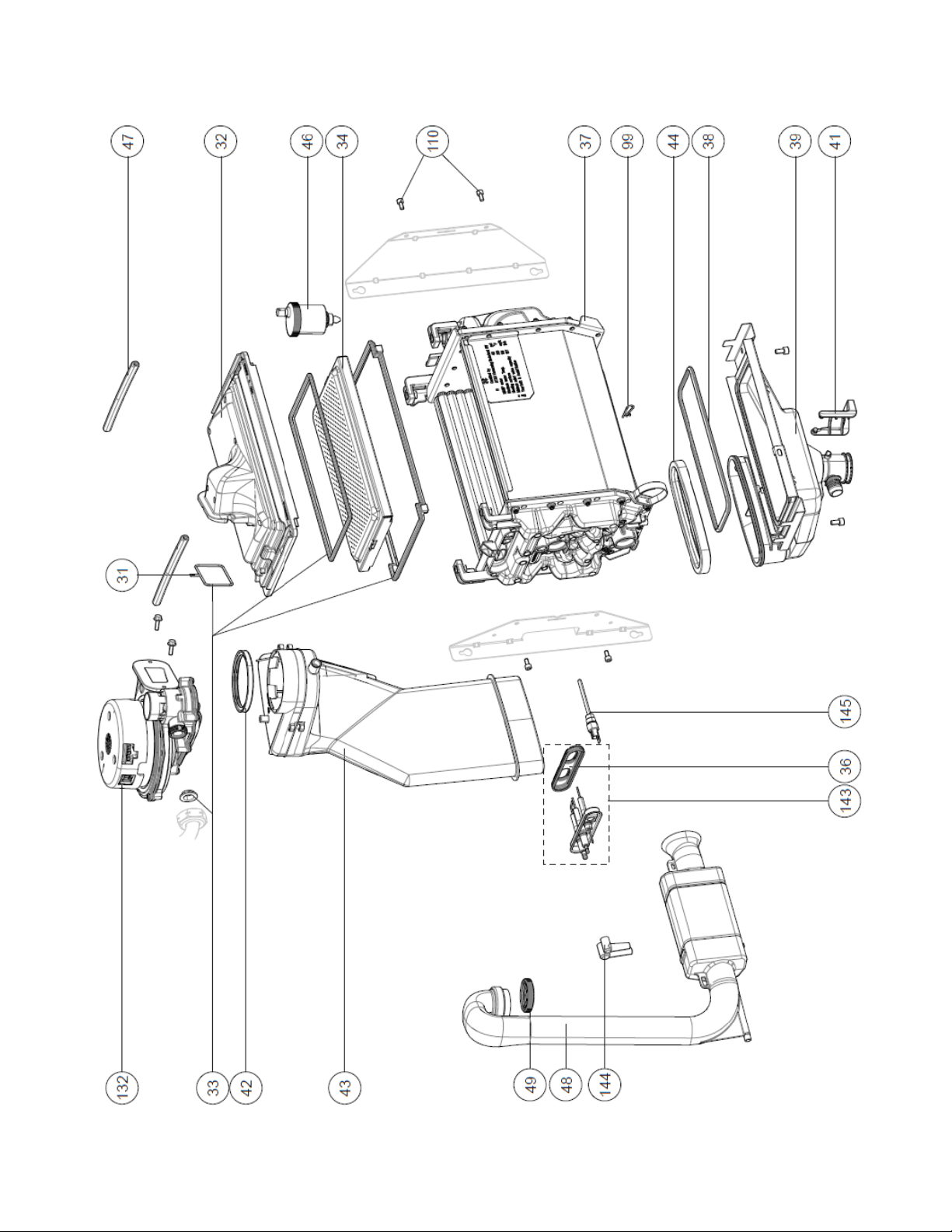
Rinnai M-Series Condensing Combi Boiler Installaon and Operaon Manual 79
Heat Exchanger
Page 80
80 Rinnai M-Series Condensing Combi Boiler Installaon and Operaon Manual
Item # Descripon Part Number Quanty
M060C M090C M120C M160C
31 Gasket 808000037 1 1 1 1
32 Burner hood
806000035 1 - - 806000036 - 1 1 1
33 Gasket kit
806000037 1 - - 806000038 - 1 1 1
34 Burner
806000032 1 - - -
806000033 - 1 1 1
36 Electrode gasket 805000062 1 1 1 1
37 Heat exchanger
807000169 1 - - 807000170 - 1 1 1
38 Condensate tray gasket
807000135 1 - - 807000136 - 1 1 1
39 Condensate tray
807000137 1 - - -
807000138 - 1 1 1
41 Condensate trap latch 807000139 1 1 1 1
42 Flue gasket 802000002 1 1 1 1
43 Exhaust vent box 802000003 1 1 1 1
44 Flue/condensate tray gasket 802000004 1 1 1 1
46 De-aerator 807000024 1 1 1 1
47 Clamp bar 809000147 2 2 2 2
48 Silencer 808000038 1 1 1 1
49 Silencer gasket 808000039 1 1 1 1
99 Water control assembly retenon clip 807000160 6 6 6 6
110 Allen head bolt M5 x10 mm 809000150 4 4 4 4
132
808000035 1 - - -
Fan/venturi
808000036 - 1 1 1
143 Ignion/Electrode assembly 805000059 1 1 1 1
144 Igniter cable 805000066 1 1 1 1
145 Supply temperature sensor 805000056 1 1 1 1
Heat Exchanger (Connued)
Page 81
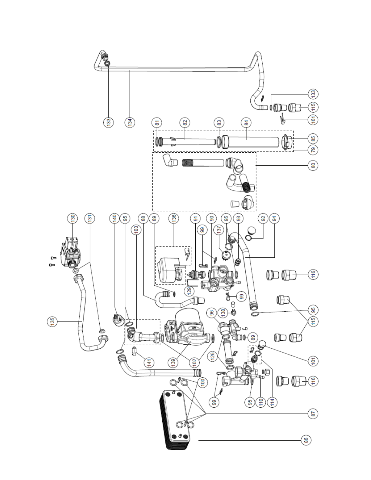
Rinnai M-Series Condensing Combi Boiler Installaon and Operaon Manual 81
Hydraulic Parts/Pipes
Page 82
82 Rinnai M-Series Condensing Combi Boiler Installaon and Operaon Manual
Item # Descripon Part Number Quanty
M060C M090C M120C M160C
79 Condensate collector kit 807000140 1 1 1 1
80 Condensate drain kit 807000141 1 1 1 1
81 Condensate drain o-ring Ø28.25 x 2.62 mm 807000142 1 1 1 1
82 Condensate drain inner tube 807000143 1 1 1 1
83 Condensate drain tube o-ring Ø37.69 x 3.53 mm 807000144 1 1 1 1
84 Condensate drain outer tube 807000145 1 1 1 1
85 Condensate collector cover gasket 807000146 1 1 1 1
86 Plate heat exchanger
807000147 1 - - -
807000148 - 1 1 1
87 Plate heat exchanger o-ring 18.64 x 3.53 mm 807000149 1 1 1 1
88 Cold water supply pipe 807000150 1 1 1 1
89 De-Aerator o-ring Ø13.94 x 2.62 mm 809000028 1 1 1 1
90 Water control assembly—return 807000151 1 1 1 1
91 3-way valve cartridge 807000152 1 1 1 1
92 O-ring Ø18 x 2 mm 809000162 1 1 1 1
93
Flow restrictor-yellow 807000154 1 - - -
Flow restrictor-blue 807000155 - 1 1 1
94 3-way valve/pump pipe 807000156 1 1 1 1
95 O-ring Ø21.89 x 2.62 mm 809000088 1 1 1 1
96 Water control assembly-supply 807000157 1 1 1 1
99 Water control pipe retenon clip 807000160 6 6 6 6
100 Bolt M3 x 30 809000149 2 2 2 2
101 Water control assembly supply plug 807000161 1 1 1 1
102 Pump gasket 1 in. 807000099 2 2 2 2
103 Pump connecon assembly 807000162 1 1 1 1
110 Allen head bolt M5 x10 mm 809000150 4 4 4 4
114 Bypass valve kit 807000167 1 1 1 1
115 Gas/DHW connecon ng 1/2 in. FNPT x 3/4
in. MNPT
806000041 3 3 3 3
116 Supply/return ng 3/4 in. FNPT x 1 in. MNPT 807000168 2 2 2 2
126 O-Ring Ø21.82 x 3.53 mm 807000153 3 3 3 3
Hydraulic Parts/Pipes (Connued)
Page 83
Rinnai M-Series Condensing Combi Boiler Installaon and Operaon Manual 83
Hydraulic Parts/Pipes (Connued)
Item # Descripon Part Number Quanty
M060C M090C M120C M160C
129 Flow sensor retenon clip 809000151 1 1 1 1
130 Gas valve 806000034 1 1 1 1
131 3/4 in. gas valve gasket 809000062 1 1 1 1
133 Yellow silicone o-ring Ø13.94 x 2.62 mm 809000055 1 1 1 1
134 Gas pipe to gas valve 806000047 1 1 1 1
135 Gas pipe/gas valve to fan 806000048 1 1 1 1
136 3-way valve actuator 807000131 1 1 1 1
137 DHW ow sensor 805000061 1 1 1 1
138 DHW sensor 805000064 1 1 1 1
139 Pump 807000132 1 1 1 1
140 Water pressure sensor 805000058 1 1 1 1
141 Return temperature sensor 805000057 1 1 1 1
161 Clip Ø19 mm 809000158 1 1 1 1
Page 84
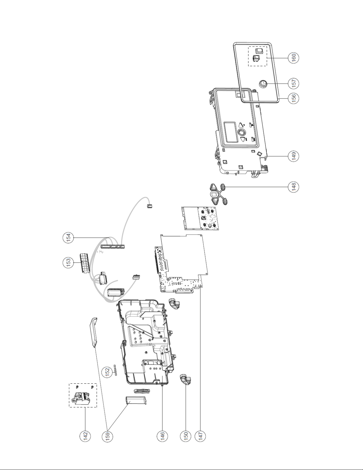
84 Rinnai M-Series Condensing Combi Boiler Installaon and Operaon Manual
Electrical Components
Page 85
Rinnai M-Series Condensing Combi Boiler Installaon and Operaon Manual 85
Item # Descripon Part Number Quanty
M060C M090C M120C M160C
142 Ignion control box 805000060
1 1 1 1
146 controller casing/back 809000152
1 1 1 1
147 PC Board 805000055
1 1 1 1
148 Key pad 805000067
1 1 1 1
149 Controller casing/front 809000153
1 1 1 1
150 Hinge support 809000154
2 2 2 2
152 Fuse 4A (250V) 805000068
1 1 1 1
153
Screw terminal-white 805000069
1 1 1 1
Screw terminal-blue 805000071
1 1 1 1
Screw terminal-red 805000072
1 1 1 1
154 Wire harness 805000073
1 1 1 1
156 Controller gasket 809000155
1 1 1 1
157 Controller scroll wheel 809000156
1 1 1 1
159 Controller cover 809000157
1 1 1 1
160 On/o switch 805000076
1 1 1 1
Electrical Components (Connued)
Page 86
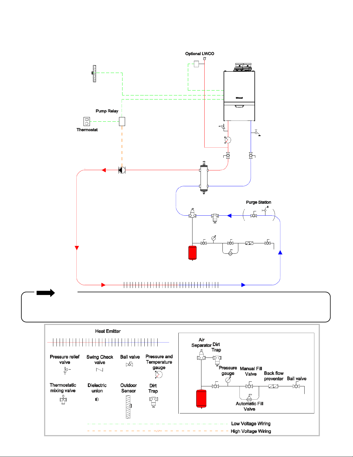
86 Rinnai M-Series Condensing Combi Boiler Installaon and Operaon Manual
System Applicaon Examples
Single Zone with Hydraulic Separaon
This picture illustrates a suggested
arrangement. Some of the ngs
are oponal.
LEGEND
NOTE
Primary/secondary piping is necessary in the following applicaons: when using external pumps; large zoned systems;
high ow applicaons; systems with high dierenal pressures; and systems with pressure drops higher than 20 FT of
head (see the Pressure Drop and Water Flow Curve in secon 13 Appendices for pressure curve informaon).
Page 87
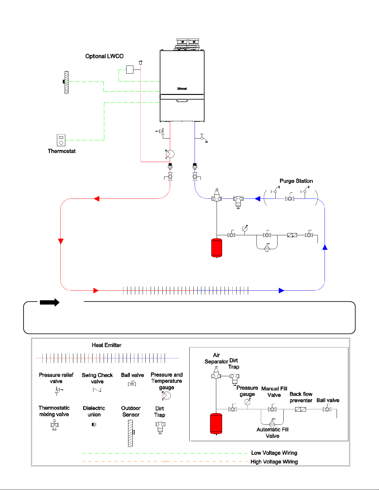
Rinnai M-Series Condensing Combi Boiler Installaon and Operaon Manual 87
Single Zone without Hydraulic Separaon
This picture illustrates a suggested
arrangement. Some of the ngs
are oponal.
LEGEND
NOTE
For systems without hydraulic separaon, care needs to be taken in reference to the pressure drop of the system
(most restricve loop) and the boiler at the necessary central heang system ow rate. Refer to the Pressure
Drop and Water Flow Curve secon in the Appendices for more informaon.
Page 88
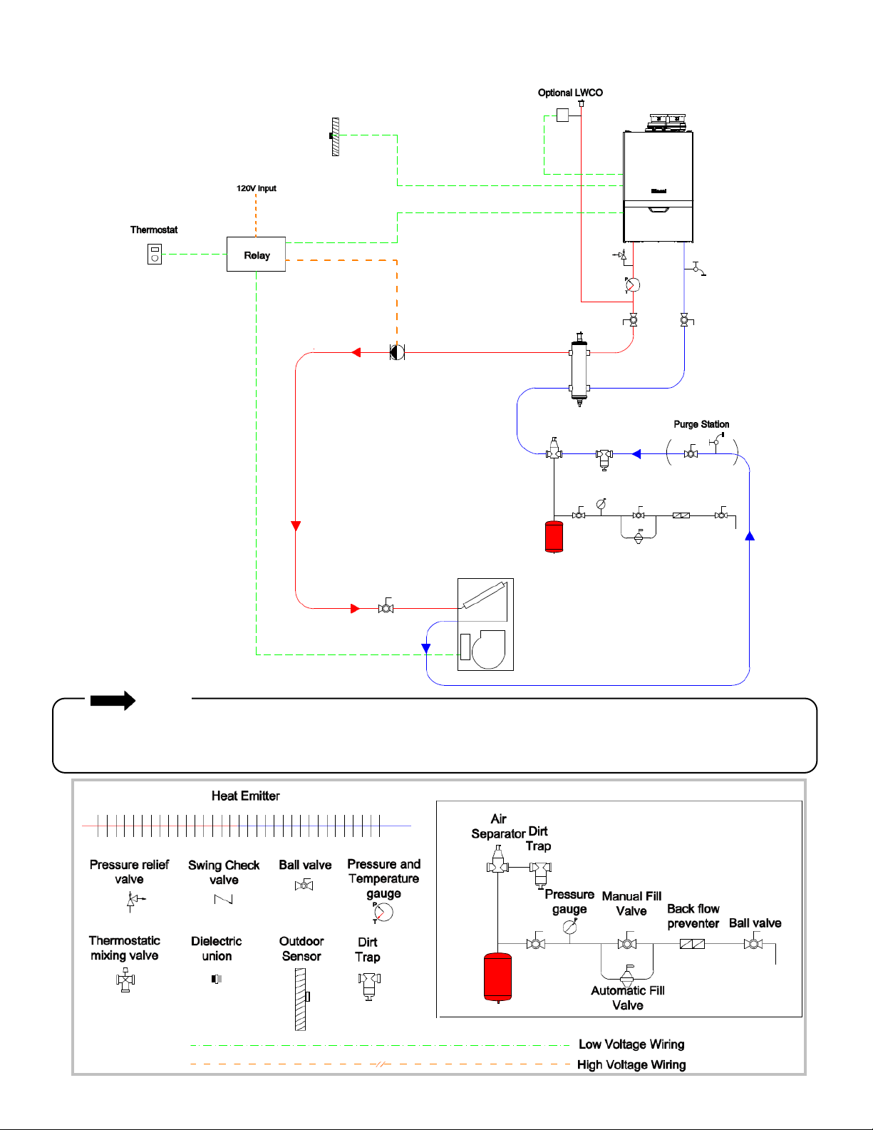
88 Rinnai M-Series Condensing Combi Boiler Installaon and Operaon Manual
Air Handler with Hydraulic Separaon
This picture illustrates a suggested
arrangement. Some of the ngs
are oponal.
LEGEND
NOTE
Primary/secondary piping is necessary in the following applicaons: when using external pumps; large zoned systems;
high ow applicaons; systems with high dierenal pressures; and systems with pressure drops higher than 20 FT of
head (see the Pressure Drop and Water Flow Curve in secon 13 Appendices for pressure curve informaon).
Page 89
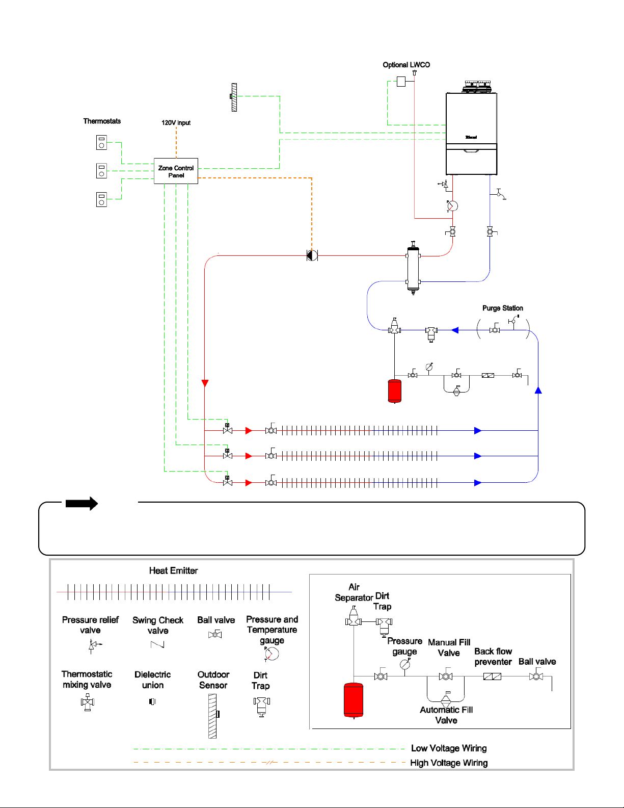
Rinnai M-Series Condensing Combi Boiler Installaon and Operaon Manual 89
Mulple Zones with Hydraulic Separaon
This picture illustrates a suggested
arrangement. Some of the ngs
are oponal.
LEGEND
NOTE
Primary/secondary piping is necessary in the following applicaons: when using external pumps; large zoned systems;
high ow applicaons; systems with high dierenal pressures; and systems with pressure drops higher than 20 FT of
head (see the Pressure Drop and Water Flow Curve in secon 13 Appendices for pressure curve informaon).
Page 90
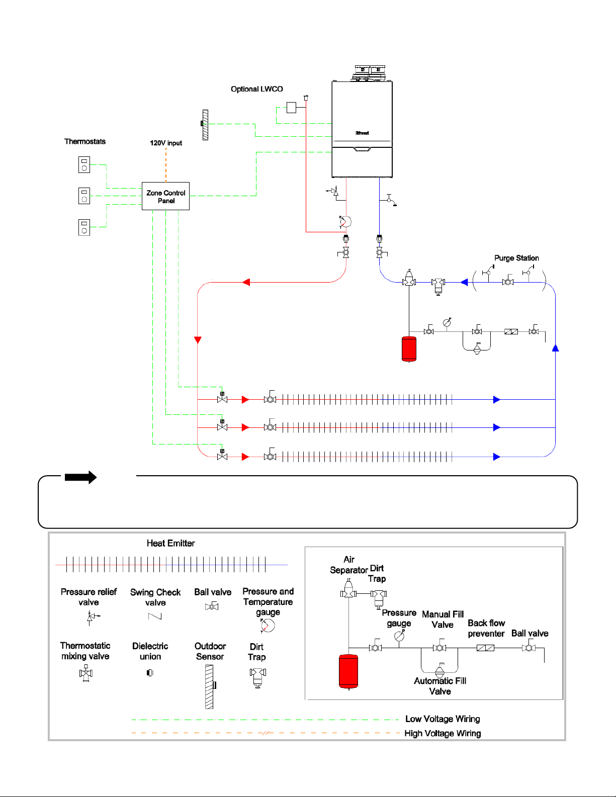
90 Rinnai M-Series Condensing Combi Boiler Installaon and Operaon Manual
Mulple Zones without Hydraulic Separaon
This picture illustrates a suggested
arrangement. Some of the ngs
are oponal.
LEGEND
NOTE
For systems without hydraulic separaon, care needs to be taken in reference to the pressure drop of the system
(most restricve loop) and the boiler at the necessary central heang system ow rate. Refer to the Pressure
Drop and Water Flow Curve secon in the Appendices for more informaon.
Page 91
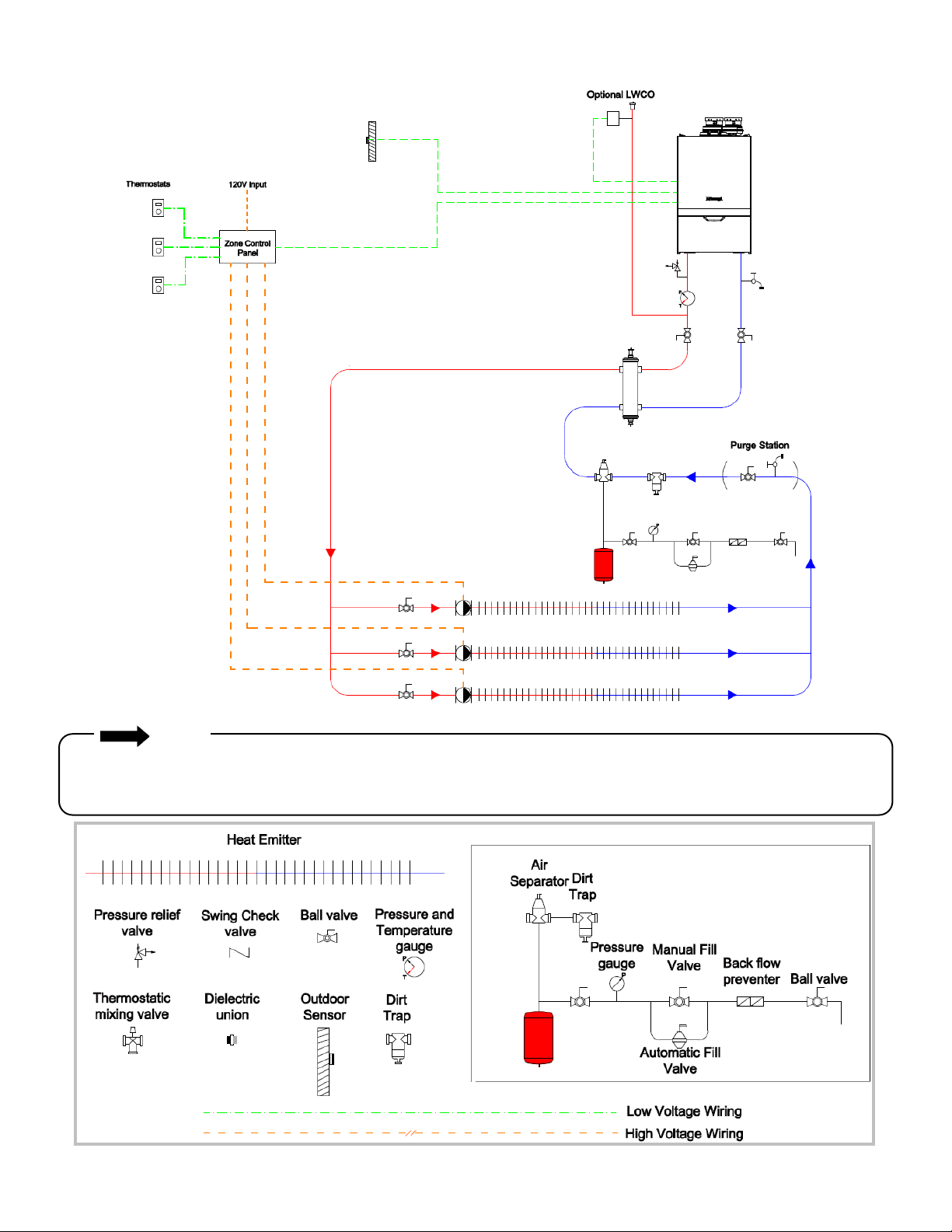
Rinnai M-Series Condensing Combi Boiler Installaon and Operaon Manual 91
Mulple Zones (with Pump) with Hydraulic Separaon
This picture illustrates a suggested
arrangement. Some of the ngs
are oponal.
LEGEND
NOTE
Primary/secondary piping is necessary in the following applicaons: when using external pumps; large zoned systems;
high ow applicaons; systems with high dierenal pressures; and systems with pressure drops higher than 20 FT of
head (see the Pressure Drop and Water Flow Curve in secon 13 Appendices for pressure curve informaon).
Page 92
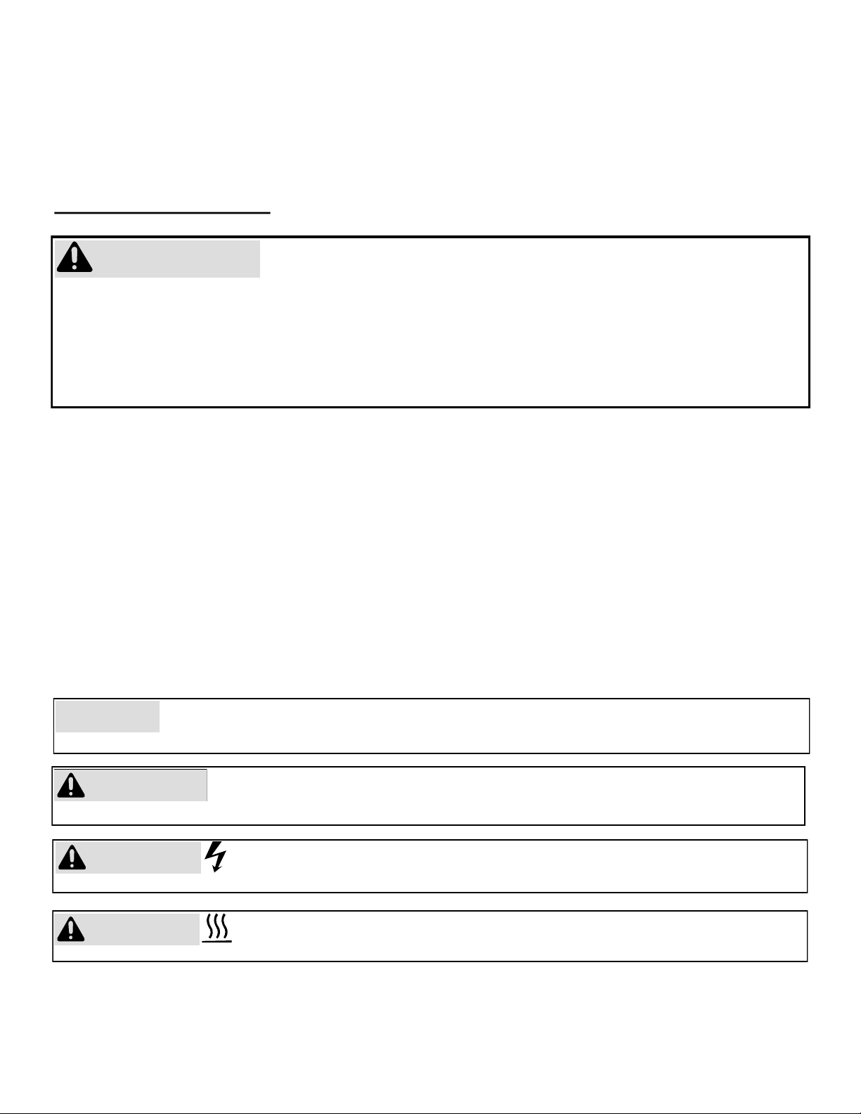
92 Rinnai M-Series Condensing Combi Boiler Installaon and Operaon Manual
This boiler is congured for Natural Gas only. To convert to Propane Gas, follow the instrucons in this secon.
WARNING
The conversion kit shall be installed by a qualied service agency in accordance with the manufacturer’s
instrucons and all applicable codes and requirements of the authority having jurisdicon. The informaon in
these instrucons must be followed to minimize the risk of re or explosion or to prevent property damage,
personal injury or death. The qualied service agency is responsible for the proper installaon of this kit. The
installaon is not proper and complete unl the operaon of the converted appliance is checked as specied in
the manufacturer’s instrucons supplied with the kit.
FOR INSTALLATIONS IN CANADA, THE CONVERSION SHALL BE CARRIED OUT IN ACCORDANCE WITH THE
REQUIREMENTS OF THE PROVINCIAL AUTHORITIES HAVING JURISDICTION AND IN ACCORDANCE WITH THE
REQUIREMENTS OF THE CGA-B149.1, NATURAL GAS AND PROPANE INSTALLATION CODE.
The appliance must be installed in accordance with:
• Local codes or, in the absence of local codes, the Naonal Fuel Gas Code, ANSI Z223.1/NFPA 54 and/or CSA B149.1,
Natural Gas and Propane Installaon Code.
• The Manufactured Home Construcon and Safety Standard, Title 24 CFR, Part 3280 and/or CAN/CSA Z240 MH
Series, Mobile Homes, Series M86 / Manufactured Home Construcon and Safety Standard, Title 24 CFR.
Conrm that the inlet gas pressure is between the minimum and maximum pressures allowed for this appliance.
If subsequent conversions are made, then a new conversion label must be placed on the boiler
to accurately reect the gas type.
NOTICE
Failure to correctly assemble the components according to these instrucons may
result in a gas leak or explosion.
CAUTION
Do not touch the areas at or near the heat exchanger or hot water lines. These areas
become very hot and could cause burns.
CAUTION
Do not touch any other areas on the PC board other than the described buons while
power is supplied to the appliance. Parts of the PC board are supplied with 120 volts AC.
Gas Conversion
Safety Precauons
WARNING
WARNING
Page 93
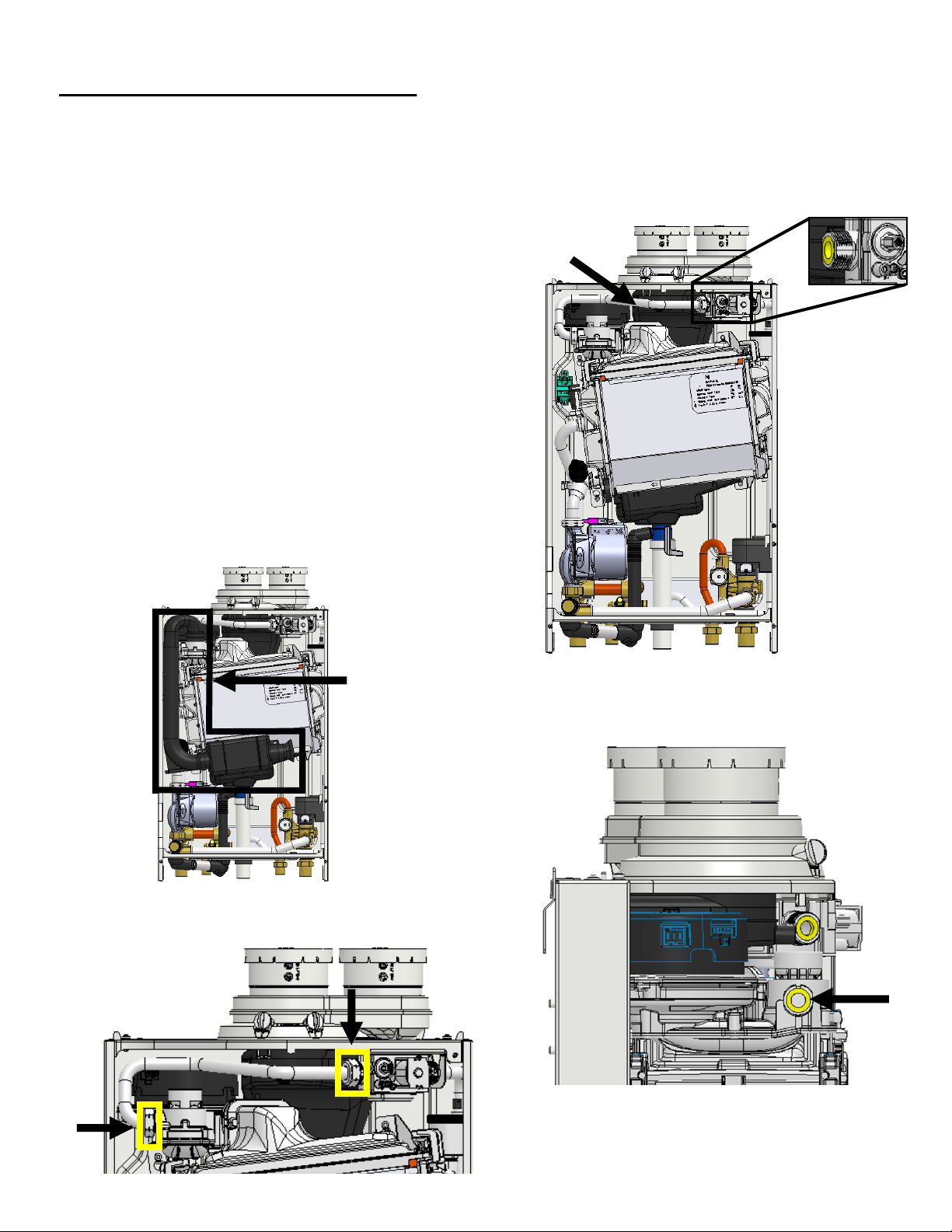
Rinnai M-Series Condensing Combi Boiler Installaon and Operaon Manual 93
5. Unscrew the gas valve and gas venturi
connecons.
7. Pull out the yellow gasket from the gas venturi.
1. Disconnect electrical power to the boiler.
2. Turn o the boiler’s gas supply by turning o
the gas control valve.
3. Remove the boiler’s front panel (for details, see
3. About the Boiler > How to Remove the
Front Panel).
4. Remove the air supply damper:
• Unclip the Velcro piece
• Li up the air supply damper to remove
and gently place aside
Gas Conversion Instrucons
Air supply
damper
Gas line
6. Remove the gas line and place aside.
Gas line removed
You Will Need:
• Conversion Kit (supplied with boiler)
• Adjustable wrench
• Combuson analyzer
Instrucons:
Page 94
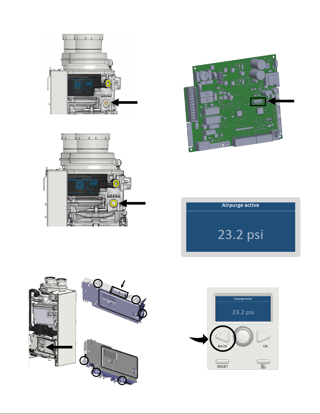
94 Rinnai M-Series Condensing Combi Boiler Installaon and Operaon Manual
9. Replace the yellow gasket into the gas venturi.
8. Remove the Liquid Propane restrictor in the gas venturi.
10. Reconnect the gas valve, gas venturi connecons
and gas line.
11. Reconnect the air supply damper.
12. Locate the controller. Remove all screw terminals
and unclip the 6 tabs from the front panel.
13. Remove the front housing of the PCB.
14. Insert the EEPROM key (included with conversion
kit) into the connector on the PCB.
18. Press the Back buon for approximately 7 seconds.
Your psi values may dier than the values shown in image.
Controller top view
Controller boom view
Screw terminals
15. Reaach the PCB front housing and screw terminals.
16. Connect electrical power to the boiler.
17. The Airpurge acve screen appears on the boiler
display.
Page 95
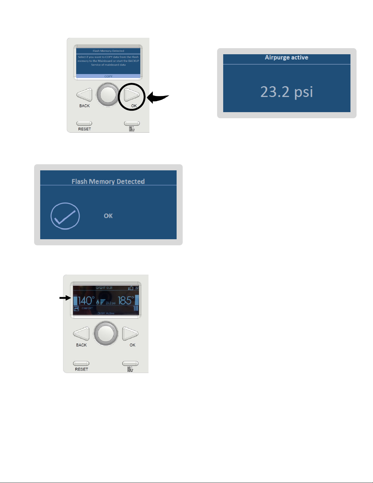
Rinnai M-Series Condensing Combi Boiler Installaon and Operaon Manual 95
19. The Flash Memory Detected screen appears. Press OK.
20. The following screen appears indicang data
parameters have been copied to the Mainboard.
21. The Home screen briey appears on the display and
then the boiler turns o.
Home
screen
22. Aer a few seconds, the boiler automacally
turns on and goes into Airpurge acve mode.
Your psi values may dier than the values shown in image.
23. Remove the EEPROM key from the PCB:
a. Disconnect power to the boiler
b. Remove the front housing of the PCB.
c. Remove the EEPROM key from the
connector.
24. Reaach the PCB front housing and screw
terminals. Clip the 6 tabs back into place.
25. Connect electrical power to the boiler. The
boiler will be back in normal operang mode
with the proper gas type parameters.
26. Replace the boiler front panel.
27. The conversion process is complete. You need
to verify the O2 sengs in minimum and
maximum input for your new gas type. See
secon 9 Commissioning for detailed
instrucons.
Page 96
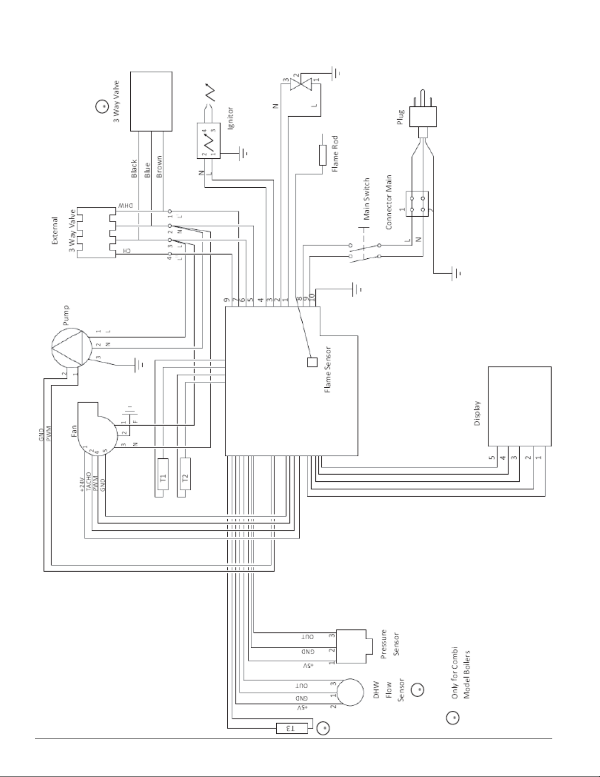
96 Rinnai M-Series Condensing Combi Boiler Installaon and Operaon Manual
Wiring Diagram
Page 97
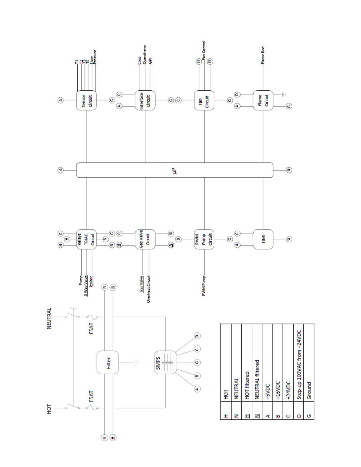
Rinnai M-Series Condensing Combi Boiler Installaon and Operaon Manual 97
Ladder Diagram
Page 98
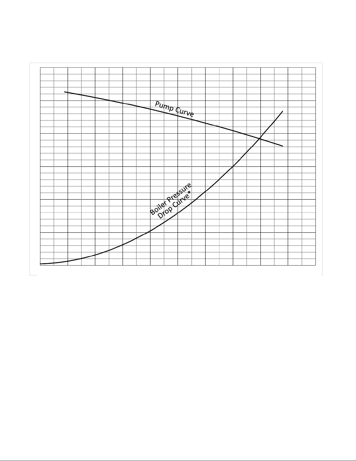
98 Rinnai M-Series Condensing Combi Boiler Installaon and Operaon Manual
0 1 2 3 4 5
6
7 8
9
10
20
15
25
30
10
5
0
Water Flow (GPM)
Pressure Loss (Feet of Head)
* Pressure drop curve applies to all M-Series Condensing Boilers (M060C, M090C, M120C and M160C).
Pressure Drop and Water Flow Curve
Page 99
Rinnai M-Series Condensing Combi Boiler Installaon and Operaon Manual 99
Resistance/Temperature Table for Sensors
Outdoor Reset Sensor (T4)
Supply Sensor (T1)
Return Sensor (T2)
DHW Sensor (T3)
NTC1k (25°C) NTC10k (25°C)
Temperature (°C) Temperature (°F) Resistance (Ω) Temperature (°C) Temperature (°F) Resistance (Ω)
-10 14.0 4.574 -10 14.0 55.047
-9 15.8 4.358 0 32.0 32.555
-8 17.6 4.152 10 50.0 19.873
-7 19.4 3.958 12 53.6 18.069
-6 21.2 3.774 14 57.2 16.447
-5 23.0 3.600 16 60.8 14.988
-4 24.8 3.435 18 64.4 13.674
-3 26.6 3.279 20 68.0 12.488
-2 28.4 3.131 22 71.6 11.417
-1 30.2 2.990 24 75.2 10.449
0 32.0 2.857 26 78.8 9.573
1 33.8 2.730 28 82.4 8.779
2 35.6 2.610 30 86.0 8.059
3 37.4 2.496 32 89.6 7.406
4 39.2 2.387 34 93.2 6.811
5 41.0 2.284 36 96.8 6.271
6 42.8 2.186 38 100.4 5.779
7 44.6 2.093 40 104.0 5.330
8 46.4 2.004 42 107.6 4.921
9 48.2 1.920 44 111.2 4.547
10 50.0 1.840 46 114.8 4.205
11 51.8 1.763 48 118.4 3.892
12 53.6 1.690 50 122.0 3.605
13 55.4 1.621 52 125.6 3.343
14 57.2 1.555 54 129.2 3.102
15 59.0 1.492 56 132.8 2.880
16 60.8 1.433 58 136.4 2.677
17 62.6 1.375 60 140.0 2.490
18 64.4 1.320 62 143.6 2.318
19 66.2 1.268 64 147.2 2.159
20 68.0 1.218 66 150.8 2.013
21 69.8 1.170 68 154.4 1.878
22 71.6 1.125 70 158.0 1.753
23 73.4 1.081 72 161.6 1.638
24 75.2 1.040 74 165.2 1.531
25 77.0 1.000 76 168.8 1.433
26 78.8 0.962 78 172.4 1.341
27 80.6 0.926 80 176.0 1.256
28 82.4 0.892 82 179.6 1.178
29 84.2 0.858 84 183.2 1.105
30 86.0 0.827 86 186.8 1.037
35 95.0 0.687 88 190.4 0.974
40 104.0 0.575 90 194.0 0.915
Page 100

100 Rinnai M-Series Condensing Combi Boiler Installaon and Operaon Manual
The instrucons shall include the test procedure set forth below:
At the me of removal of an exisng boiler, the following steps shall be followed with each other appliances remaining
connected to the common venng system are not in operaon.
1. Seal any unused openings in the common venng system.
2. Visually inspect the venng system for proper size and horizontal pitch and determine there is no blockage or
restricon, leakage, corrosion and other deciencies which could cause an unsafe condion.
3. Insofar as is praccal, close all building doors and windows and all doors between the space in which the
appliances remaining connected to the common venng system are located and other spaces of the building.
Turn on clothes dryers and any appliance not connected to the common venng system. Turn on any exhaust
fans, such as range hoods and bathroom exhausts, so they will operate at maximum speed. Do not operate a
summer exhaust fan. Close replace dampers.
4. Place in operaon the appliance being inspected. Follow the lighng instrucons. Adjust thermostat so
appliance will operate connuously.
5. Test for spillage at the dra hood relief opening aer 5 minutes of main burner operaon. Use the ame of a
match or candle, or smoke from a cigaree, cigar, or pipe.
6. Aer it has been determined that each appliance remaining connected to the common venng system
properly vents when tested as outlined above, return doors, windows, exhaust fans, replace dampers, and
any other gas-burning appliance to their previous condion of use.”
7. Any improper operaon of the common venng system should be corrected so the installaon conforms with
the Naonal Fuel Gas Code, ANSI Z223.1/NFPA 54, and/or the Natural Gas and Propane Installaon Code,
CAN/CSA B149.1. When resizing any poron of the common venng system, the common venng system
should be resized to approach the minimum size as determined using the appropriate tables in Chapter 13 of
the Naonal Fuel Gas Code, ANSI Z223.1/NFPA 54, and/or the Natural Gas and Propane Installaon Code,
CAN/CSA B149.1.
If a boiler is removed from a common vent system, the common vent system is likely to be too large for proper venng
of the remaining appliances connected to it.
Remove a Boiler From a Common Vent System
 Loading...