

Rinnai Infinity Series Installation Manual
Infinity Storage Packs
Installation Manual
IMPORTANT
Read these instructions carefully before attempting
installation or use of this appliance. All work must be carried
out by competent persons.
1

CONTENTS
CONTENTS 2
USER INSTRUCTIONS
Warnings 3
Building Operator's Duty of Care 5
Rinnai Storage Package Contents 6
Basic Operating Principle 7
INSTALLATION
Planning out the Site 8
Water Heater Pipework 9
Schematics 10
Unvented Kit 12
Hot Water Storage Cylinder 14
Cylinder Dimensions 15
System Design Recommendations 18
System Controls 20
Wiring Diagram 21
Extra Pump 22
Extra Cylinder 22
Pump Data 23
Commissioning Procedure 24
Commissioning Record 26
Service Record 27
UK Warranty 28
Warranty Registration 30
Contact 32
2

WARNINGS
THIS MANUAL SHOULD BE READ IN
CONJUNCTION WITH THE
INSTALLATION MANUAL FOR THE
RINNAI WATER HEATERS
PLEASE READ ALL FOLLOWING
INSTRUCTIONS FULLY
FAILURE TO FOLLOW THESE
INSTRUCTIONS AND PIPING
SCHEMATICS IMPLICITLY COULD
CAUSE SERIOUS INJURY AND DAMAGE
TO PROPERTY.
ANY WARRANTY CLAIMS WILL BE
NEGATED AND RINNAI UK WILL NOT
BE HELD ACCOUNTABLE FOR ANY
DAMAGE OR THIRD PARTY CLAIMS
3

WARNINGS
Persons carrying out installation work on the Rinnai Infinity Hot Water Package require the following
certificates
For any gas work carried out: Gas Safe Register Registration and ACS certification For installation of
the Hot water system: proof of competence which can be shown through a Registered Operative
Identity Card for the installation of Unvented Domestic Hot Water Systems or the Association of
Installers of Unvented Hot Water Systems (Scotland and Northern Ireland.) For installation of electrical
wiring: EIC certification. IEE 16th Edition
Building Regulation G3 draws attention to the Building Regulations 1991, especially
Regulation 11(1), 12(4), and 13(3). The following is quoted from these and Building Regulation
G3.
A person who intends to carry out building work or to make a material change of use shall -- give to the
local authority full plans and a building notice accompanied by a statement which specifies:
a: the name, make, model and type of hot water storage system to be installed
b: the name of the body, if any, which has approved or certified that the system is capable of
performing in a way which satisfies the requirements of paragraph G3 of Schedule 1.*
c: the name of the body, if any, which has issued any current registered operative identity card to the
installer or proposed installer of the system.
The full plans shall consist of a description of the proposed building work or material change of use,
and the plans, particulars and statements required.
*In the Secretary of State’s view requirement G3 will be met if a hot water storage system that has a
storage vessel with no vent pipe to the atmosphere:
a: has been installed by a competent person
b: has safety devices that prevent the temperature of the stored water at any time exceeding
100°C;
c: has pipework that safely conveys the discharge of hot water from safety devices to where it is visible
but will cause no danger to persons, in or about the building.
The Rinnai Infinity hot water storage system, like most systems over 150 litres capacity, has been
supplied as a package with the necessary safety devices to prevent the temperature of the stored water
from exceeding 100°C. It is the responsibility of the installer to make sure that proper certification has
been gained, and that the system is installed to the requirements of G3 and of this installation manual.
Additionally the installation must be carried out to the requirements of Building
Regulations issued by the Department of the Environment Building Standards
(Scotland) Regulations.
I.E.E. Wiring regulations for electrical installations. BS 6700 Local byelaws Water regulations Health
and safety at work etc. Act 1974
Such other specifications and regulations that may supersede or complement the above documents.
Additional documents listed in the Infinity water heater manual.
Disposal Information:
Under the laws and local regulations, all items must be disposed separately from household waste.
When this product reaches the end of useful life, it should be taken to a collection point identified by
the local authorities. The recycling of the product at the time of disposal will help conserve natural
resources and ensure that it is recycled in a manner that protects human health and environment.
4

BUILDING OPERATORS DUTY OF CARE
Any owner of a domestic hot water system has a duty of care to protect employees and the public from
the possible dangers of hot water systems including scalding or Legionella. Although this document is
not intended to give expert advice on ways to avoid these issues it should give a guideline to what
should be done and where more information can be found. The full list of responsibilities can be found
in the following documents
TM13 CIBSE: Minimising the Risk of Legionnaires Disease ACOP L8: The Control of Legionella
Bacteria in Water Systems HSE publication: Legionnaires Disease: A guide for employers Various
other documents that are industry specific such as HSE publication: Controlling Legionella in Nursing
and Residential Homes NHS Estates HTM 2040 The Control of Legionella in Healthcare Premises: a
code of practice. and HTM 2027 Hot and Cold Water Supply, Storage and Mains Services. There are
many industry specific documents regarding the distribution of hot water. These can be found in IP
14/03 from the BRE: Preventing Hot Water Scalding In Bathrooms: Using TMVs
This list is not comprehensive.
The responsibilities, relative to the Rinnai Infinity type of hot water system, can be summarised in the
following way.
Water temperatures in cylinders should always be over 600C. A secondary return must return at over
500C. The water at the furthest outlets must reach 500C within 60 seconds.
Warning signs should be placed over taps where the temperature could exceed 550C. Where people
are at high risk consider thermostatic mixing valves.
A risk assessment should be carried out, by a suitable person, to gauge the associated risk of the hot
water system. This assessment should be reviewed at regular intervals.
Based on this assessment a maintenance regime should be determined. The hot water system and
Infinity water heaters must be serviced annually. This alone is not sufficient. Some parts of the hot
water system, such as rarely used shower heads or terminal fittings, will require frequent maintenance.
Frequent checks should be carried out to ensure the hot water system is operating correctly.
The system must be commissioned by a qualified person.
5

RINNAI STORAGE PACK CONTENTS
This Rinnai Hot Water Pack should consist of the following:
Set of 3 Valves (Hot, Cold, Gas) Equal to number of heaters
1 x Hot water cylinder
Valve Pack Corresponding to the Size of Hot Water Cylinder
1 x Primary Pump
1 x Mains Valve Kit
1 x Expansion Vessel
1 x TSTAT1 (Control Thermostat)
1 x TSTAT2 (Safety Thermostat/High Limit Thermostat)
1 x Temperature and Pressure Relief Valve
1 x MC91 Controller (for diagnostics only not to be left connected to heater)
1 x Installation Manual and Service Log
Optional Extra
Water Conditioner in Hard Water Areas (recommendation in ACOP L8 2014)
6

BASIC OPERATING PRINCIPLE
When the water temperature is below the set point (normally 600C) the thermostat contacts
(TSTAT1) will close and allow power to the circulating, primary pump.
The pump will start circulating water from the bottom of the storage cylinder up through the Rinnai
Water Heater(s) to be heated and returned to the cylinder. The Rinnai Water Heater(s) see this the
same as a hot water tap opening and will ignite and start heating water. (Rinnai Water Heater(s)
should be pre set to 750C on the dip switches)
When the thermostat reaches its set temperature the thermostat contacts open and the circulating
pump will stop. As water has stopped flowing the Rinnai Water Heater(s) will shut off.
It is normal for the burner on the Rinnai Water Heater(s) to modulate back to a low burner rate as
the water temperature within the storage cylinder rises near to thermostat set temperature.
At times of no demand the primary pump will draw water out of the bottom of the cylinder to reheat it as
and when required due to the heat loss of the vessel.
At times of heavy draw off the mains water will feed into the bottom of the cylinder and into the Rinnai
Water Heater(s). The system has been correctly sized to give the right mix of mains water heated to
750C and mains water straight into the cylinder to have no effect on the overall temperature of the hot
water supply.
The system has been designed to allow for an outlet temperature of 600C with an incoming mains
temperature of 100C
7

When choosing the location of the Infinity hot water package the following should be taken
into account.
1. The cylinder has a necessary clearance of 100mm to the back and sides, 600mm to the front, and
200mm above.
2. The water heaters should mount on a wall or suitable framework as near as possible to the storage
cylinder to minimise pipe work losses.
3. There are internal and external water heaters so there are options available in locating the water
heaters. The cylinders must be mounted indoors.
4. There must be enough gas available for the entire load of the water heaters.
5. There must be water and electric available.
6. The floor must be strong enough to support the full weight of the cylinder when full.
PLANNING OUT THE SITE
7. There should be enough room and lighting to service the units.
8. If the heaters are at high level, or access is by means of a ladder, there should be a ladder or
scaffolding available onsite at all times.
9. There must be suitable drainage available so that if there was a leak at any time from the heaters
or cylinder, including a leak of hot water, it would not cause damage to the building, furnishings, or
inhabitants.
10. There must be a suitable place when using internal units to get the flues out of the building in a
safe manner.
8

WATER HEATER PIPEWORK
Flow Rates
The primary pumps supplied with the hot water packages are designed to give a flow rate through
each unit of 16 litres/minute.
The pipework should be sized for a minimal pressure drop through the pipework. The total flow through
the header can be found by multiplying the number of units by 16 l/min.
The branches from the header pipe to and from each heater should be in 22mm.
The following guideline can be used when the heaters are near as possible to the cylinder.
For heaters separated from the cylinder the size of the pipe work may have to be increased. The pipe
sizes given are for Primary pipe work including the cold water header from the primary pump to the last
branch, and the hot water header from the outlet of the first heater to the connection point on the
cylinder.
1 heater: 16 l/min 22 mm
2 heaters: 32 l/min 28 mm
3 heaters: 48 l/min 28 mm
4 heaters: 64 l/min 35 mm
5 heaters: 80 l/min 42 mm
6 heaters: 96 l/min 42 mm
Insulation.
All pipe work should be insulated to minimise heat loss.
9
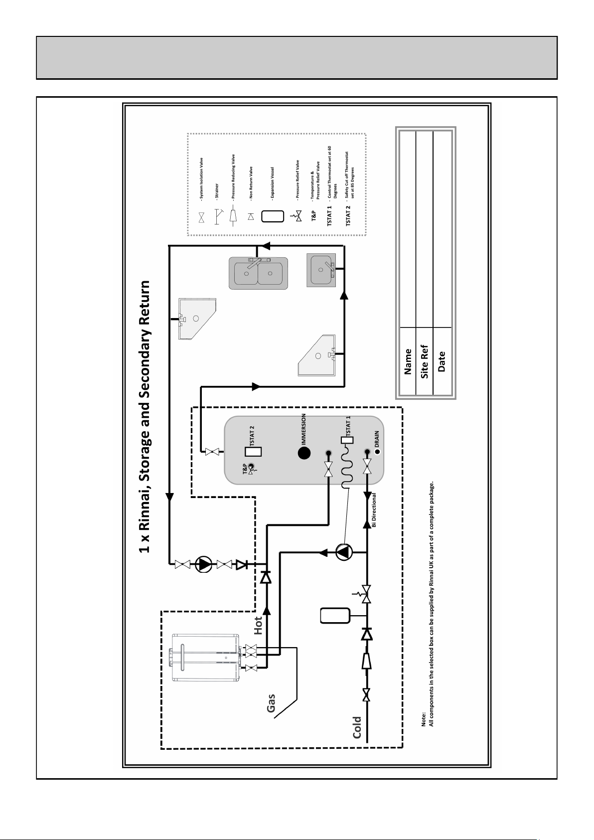
SCHEMATIC
10
 Loading...