

Rinnai INFINITY REU-3203W Service Manual
INFINITY
REU-3203W
Infinity High Capacity Continuous Flow Gas Hot Water System
SERVICE MANUAL

ISO 9001 Model for Quality Assurance in design/development, production, installation and servicing,
aimed primarily at achieving customer satisfaction by preventing nonconformity at all stages
from design through to servicing.
ISO 9002 Same as ISO 9001 but excluding design.
AG 102 Approval requirements for gas water heaters as set by The Australian Gas Association and
Australian Liquefied Petroleum Gas Association Ltd, to ensure proper safety performance and
quality levels are achieved.
Proudly a member of The Australian Gas Association.
All of our products are AGA tested and approved.
Distributed and serviced in Australia under a
Quality System certified as complying with ISO
9002 by Quality Assurance Services.
Rinnai New Zealand has been certified to ISO 9001
Quality Assurance by Telarc.
Certified to WaterMark by Quality Assurance
Services. WaterMark certification is awarded to
products and fittings complying with safety and
water contamination standards.
Comparative Energy Consumption tested to The
Australian Gas Association requirements of Australian
Gas Code AG 102. An energy rating of 5 stars refers to
an efficiency of approximately 80%, that is, 80% of gas
consumed is converted to useful heat.

© Copyright Rinnai Australia Pty Ltd ABN 74 005 138 769 ACN 005 138 769
All rights reserved
Produced by Customer Technical Services
April 2001 - 1st print
No portion or part of this manual may be copied without prior permission from Rinnai Australia.
Rinnai Australia takes no responsibility for the accuracy or otherwise of information contained in
this manual, and reserves the right to make modifications and change specifications without notice.
Failure to comply with these instructions may result in serious personal injury or damage to the appliance.
This manual has been published by Rinnai Australia Technical Services. We welcome
users of this manual to provide feedback and suggestions for improvement purposes.
SM3203
Issue N
o
1
WARNING
ALL WIRING INSIDE THIS APPLIANCE MAY BE AT 240 VOLTS POTENTIAL
ALL SERVICE WORK MUST BE CARRIED OUT BY AN AUTHORISED PERSON.
DO NOT TEST FOR GAS ESCAPES WITH AN OPEN FLAME

Infinity REU-3203W ©Rinnai
Table of Contents
Glossary of Terms and Symbols .................................................................... i
1. Introduction ................................................................................................... 1
2. Specifications ................................................................................................ 2
3. Water Flow Rates and Pressures ................................................................. 4
4. Dimensions ................................................................................................... 7
5. Installation ..................................................................................................... 8
6. Remote Controls ........................................................................................... 9
7. Cutaway Diagram ....................................................................................... 11
8. Operational Flow Chart ............................................................................... 12
9. Operation Principles ................................................................................... 14
10. Main Components ..................................................................................... 15
11. Time Charts .............................................................................................. 16
12. Wiring Diagram ......................................................................................... 17
13. Dip Switch Settings ................................................................................... 18
14. Fault Finding ........................................................................................................ 21
15. Component Circuit Value Table ................................................................ 24
16. Component and Circuit Checks ................................................................ 26
17. Maintenance Monitor / Error History ......................................................... 37
18. Gas Pressure Setting Procedure .............................................................. 39
19. Gas Conversion Procedure ...................................................................... 41
20. Dismantling for Service ............................................................................. 43
21. Exploded Diagram .................................................................................... 49
22. Parts List ................................................................................................... 53

Infinity REU-3203W - i - ©Rinnai
Glossary of Terms and Symbols
dB(A) - sound pressure level in decibels, “A” range
DC - direct current
AC - alternating current
WFCD - water flow control device
FB - feedback information
FF - feedforward information
Hz - Hertz
IC - integrated circuit
kcal/h - kilocalorie per hour
kPa - kilopascals
LED - light emitting diode
L/min - Litres per minute
mA - milliamps
MJ/h - megajoule per hour
mm - millimetres
mmH
2
O - millimetres of water (gauge pressure)
OHS - overheat switch
PCB - printed circuit board
CPU - central processing unit
POT - potentiometer
rpm - revolutions per minute
SV - solenoid valve
ø - diameter
o
C - temperature rise above ambient
POV - modulating valve
TE - thermal efficiency
TH - thermistor
T
IN
- temperature of incoming water
T
OUT
- temperature of outgoing water
∆

Infinity REU-3203W - 1 - ©Rinnai
1. Introduction
The Brand Name "Infinity" refers to "Endless Hot Water." The Infinity series represents the latest
technology in continuous flow, temperature controlled hot water.
Features
• The Infinity 32 NEVER RUNS OUT of hot water. Whilst electricity, water and gas supplies are
connected, hot water is available whenever hot water taps are open.
• Built into the main micro-processor is the facility to LIMIT THE MAXIMUM TEMPERA-
TURE of the hot water supplied. The water temperature may be limited to various maximum
temperatures. This is particularly useful when the hot water unit is installed where young children or the infirm may be using the hot water. The Infinity is delivered with a maximum preset
temperature of 55 C. If required, the temperature limits can be changed by a service technician. For further information, please contact Rinnai.
• The Infinity is a power flued appliance. It is COMPACT, saving both floor and wall space.
• The temperature of outgoing hot water is CONSTANTLY MONITORED by a BUILT-IN
SENSOR. If the temperature of the outgoing hot water rises to more than 3 C above the
selected temperature shown on the Digital Monitor (or the pre-set limit when Remote Controls
are not fitted), the burner will automatically go out. The burner will ignite again once the outgoing hot water temperature falls below the temperature shown on the Digital Monitor (or the preset limit).
• The burner lights automatically when the hot water tap is opened, and goes out when the tap is
closed. IGNITION IS ELECTRONIC, therefore there is not pilot light. When the hot water
tap is off, no gas is used.
• ’Deluxe’ or ’Standard’ Remote Controllers are available as an optional extra. Depending on the
models chosen, these offer the following additional features :
- Bath fill function
- Voice Prompting
- Localised Temperature Control for up to one kitchen and two bathroom controllers
- Clock
• Temperatures selected at the controllers are retained in the SYSTEM MEMORY.
• Operating NOISE LEVEL IS VERY LOW.
• ERROR MESSAGES ARE DISPLAYED on the Remote Controllers, assisting with service.
°
°

Infinity REU-3203W - 2 - ©Rinnai
2. Specifications
Note 1: The default factory setting is 55 C. The unit can be ordered from Rinnai to be pre-set to any of the
other temperatures listed. The unit can be pre-set to any of the temperatures listed by a suitably
qualified person, except 85 and 95 C. Conversion to 85 and 95 C must be performed by Rinnai.
Controllers are available with default temperatures up to 75 C. When fitted with controllers, only
temperatures not exceeding the default temperatures can be selected. When fitted without controllers,
the unit will deliver water at the default temperature. Controllers are not available with 85 and 95 C
settings.
Note 2: Unit will operate at lower pressures but the maximum rated flow of 32L/min. will not be achieved.
Model No. REU - 3203W
Name of Appliance Continuous Flow Gas Hot Water Unit
Exhaust System Force Combustion
Installation Externally Wall Mounted
Available Default Temperatures (Note 1):
40, 43, 50, 55, 65, 75, 85 and 95 C
Temperature Range
37 to 55 C in 13 steps
Dimensions
(mm)
Width 470
Height 600
Depth 220
Weight (Kg ) 2 9
Connections
Gas 20A (R3/4)
Cold Water Supply 20A (R3/4)
Hot Water Supply 20A (R3/4)
Ignition Method Continuous Electrical Discharge, Direct Ignition
Gas Consumption
Natural Gas 250 MJ/h
Propane 250 MJ/h
Hot Water Delivery Capacity
2.7 ~32 L/min. (raised 25 C)
Minimum Operating Water Flow 2.7 L/min
Minimum Operating Pressure (Note 2): 180kPa
Nominal Operating Pressure 200~1000kPa
Power Supply
Infinity Unit AC 240V (50Hz)
Remote Control(optional) DC 12V from Infinity unit by 2 core cable
Electrical
Consumption
Normal 83W
Standby 12W (No controllers)
°
°
°
°
°°
°
°

Infinity REU-3203W - 3 - ©Rinnai
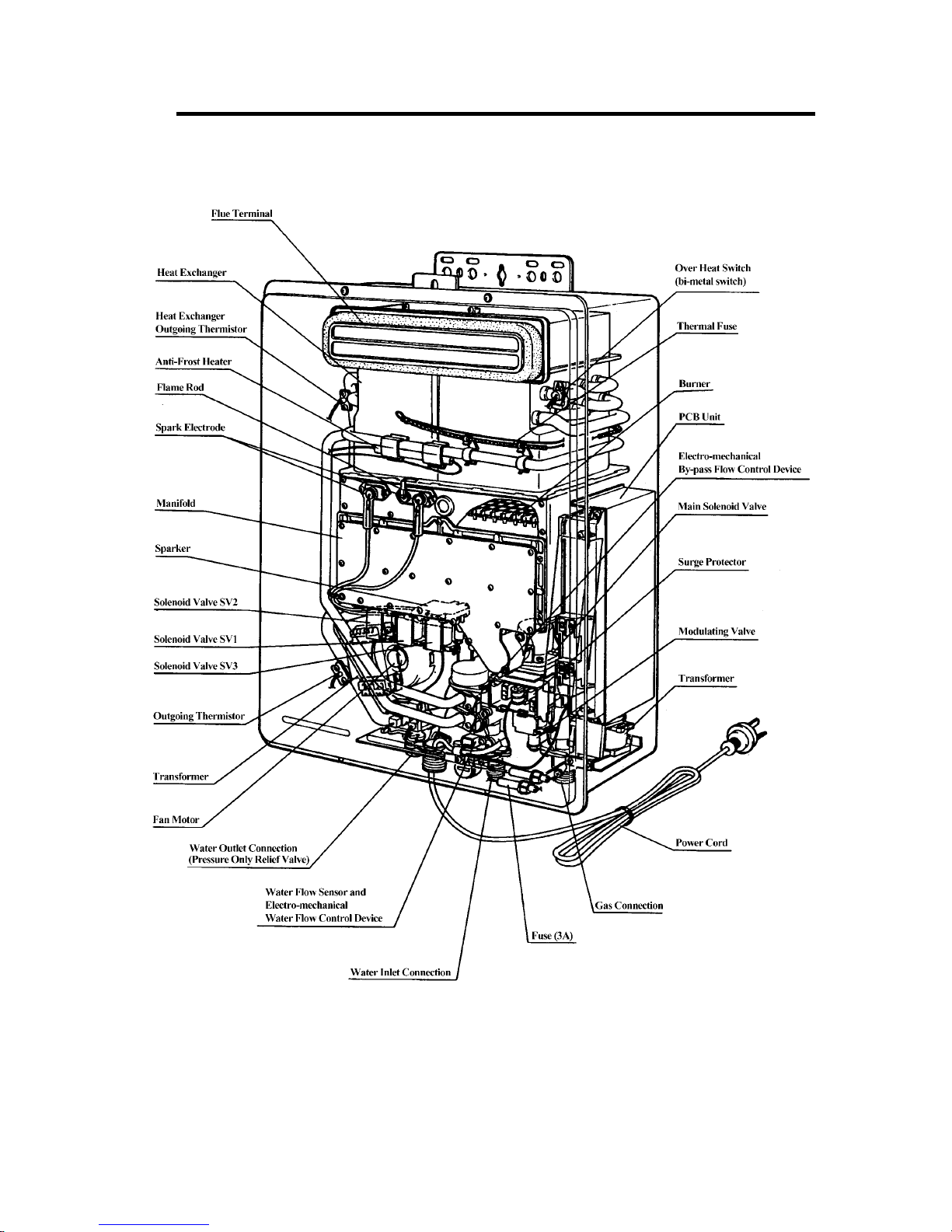
Sensors and Safety Devices
• Heat Exchanger Thermistor: Measures hot water temperature at heat exchanger outlet. If water
temperature reaches a predetermined limit, gas supply is stopped.
• Hot Water Delivery Thermistor: Measures hot water temperature at the outlet valve (i.e. the
‘mixed’ temperature).
• Flame Rod: Monitors combustion characteristics inside the combustion chamber. If the flame
fails, gas supply is stopped.
• Overheat Switch: Situated on the heat exchanger, gas supply is stopped when water temperature
reaches 97 C for a number of seconds.
• Fusible Link: Situated on the heat exchanger, electrical power supply is stopped if the
temperature exceeds 129 C.
• Water Pressure Relief Valve: Safeguards the water circuit against excessive inlet pressure. Opens
at 2100kPa, closes at 1500kPa.
• Electrical Fuse: (3A glass fuse) prevents against over-current.
• Surge Protector: prevents against over-current.
• Boil Dry Prevention: If water flow sensor detects no flow, gas supply is stopped.
• Combustion Fan Speed Sensor: In case of combustion fan defect (no rotation of fan) gas supply
is stopped.
• Temperature Cutout: If the delivered hot water temperature rises above the required delivery
temperature for a number of seconds, the gas supply is stopped.
Combustion Specifications
* * The TPP is measured with the cover off the appliance at the regulator test point with supply pressures of
1.13kPa (NG) and 2.75kPa(Propane).
* * * Value for New Zealand LPG
Gas Type Injector
Size (mm)
Nominal TPP (kPa) * * NGC (MJ/hr)
Low High Low High
Natural
1.05
0.18 0.74 20 250
1.65
Propane
( NZ LPG )
0.65
0.35
1.76
( 1.53 ) * * *
20 250
0.95
°
°

Infinity REU-3203W - 4 - ©Rinnai
3. Water Flow Rates and Pressures
Water Flows
Table 1 shows unmixed and mixed water flow rates and approximate gas consumptions for various
temperature rises. The unmixed flow rates are the flow rates available at the given temperature rise
directly at the outlet of the water heater. The mixed water flow rates are available at the given
temperature rise by mixing hot water from the outlet of the water heater with cold water from the
mains supply.
Water Flows can also be calculated by the following formula:
M = 60 x ( Q / C x T )
Where M = Water flow rate in litres/minute. If M is ≤ to 32, the water is unmixed. If M is >32, the
water is mixed.
Q = Heat energy available in kW = 56kW for the REU3203W
C = Specific heat of water = 4.2KJ/Kg C. C does not change for the purpose of this calculation.
T = Temperature rise required ( C)
Example:
What is the flow rate available with an incoming water temperature of 10 C and a required
temperature of 20 C?
T = 20 - 10 = 10 C
Q = 56
C = 4.2
M = 60 x ( 56 / (4.2 x 10) ) = 80 l/min. Since 80 is greater than 32, this flow rate is mixed. This result
corresponds with the value in Table 1.
∆
°
∆°
°
°
∆°

Infinity REU-3203W - 5 - ©Rinnai
Table 1: Approximate Water Flows and Gas Usage - Rinnai Infinity REU-3203W
Temperature
Rise C
51015
L/
min
L/hr MJ/hr L/
min
L/hr MJ/hr L/
min
L/hr MJ/hr
unmixed 32.0 1920.0 50.0 32.0 1920.0 100.0 32.0 1920.0 150.0
mixed
Temperature
Rise C
20 25 30
L/
min
L/hr MJ/hr L/
min
L/hr MJ/hr L/
min
L/hr MJ/hr
unmixed 32.0 1920.0 200.0 32.0 1920.0 250.0 26.5 1589.0 250.0
mixed 40.0 2400.0 250.0 32.0 1920.0 250.0 26.5 1589.0 250.0
Temperature
Rise C
(unmixed and
mixed)
35 40 45
L/
min
L/hr MJ/hr L/
min
L/hr MJ/hr L/
min
L/hr MJ/hr
22.7 1362.0 250.0 19.9 1191.0 250.0 17.7 1059.0 250.0
Temperature
Rise C
(unmixed and
mixed)
50 55 60
L/
min
L/hr MJ/hr L/
min
L/hr MJ/hr L/
min
L/hr MJ/hr
15.9 953.0 250.0 14.4 867.0 250.0 13.2 794.0 250.0
Temperature
Rise C
(unmixed and
mixed)
65 70 75
L/
min
L/hr MJ/hr L/
min
L/hr MJ/hr L/
min
L/hr MJ/hr
12.2 733.0 250.0 11.3 681.0 250.0 10.6 635.0 250.0
Temperature
Rise C
80 85 90
L/
min
L/hr MJ/hr L/
min
L/hr MJ/hr L/
min
L/hr MJ/hr
9.9 596.0 250.0 9.3 561.0 250.0 8.8 530.0 250.0
°
°
°
°
°
°
Infinity REU-3203W - 6 - ©Rinnai
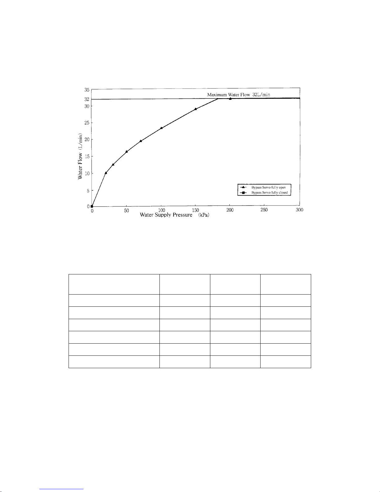
Water Pressure
As seen in the table below a minimum supply pressure of 180kPa is required to operate at the rated
flow of 32 L/min. In an actual installation, pressure losses in the plumbing system also need to be
considered.
Time Required for Bath Fill
(Bath Fill temperature=42 C, water pressure 200kPa ((2.04kgf/cm2))
Ambient Water Temp.
Bath Volume
25
o
C15
o
C
5
o
C
100 L ~ 2.5 mins ~ 2.7 mins ~ 2.2 mins
160 L ~ 3.5 mins ~ 5.5 mins ~ 7.5 mins
180 L ~ 4 mins ~ 4.5 mins ~ 6.5 mins
220 L ~ 5.5 mins ~ 6 mins ~ 8 mins
260 L ~ 6.5 mins ~ 7 mins ~ 9.5 mins
320 L ~ 7 mins ~ 11 mins ~ 15 mins
°
Infinity REU-3203W - 7 - ©Rinnai
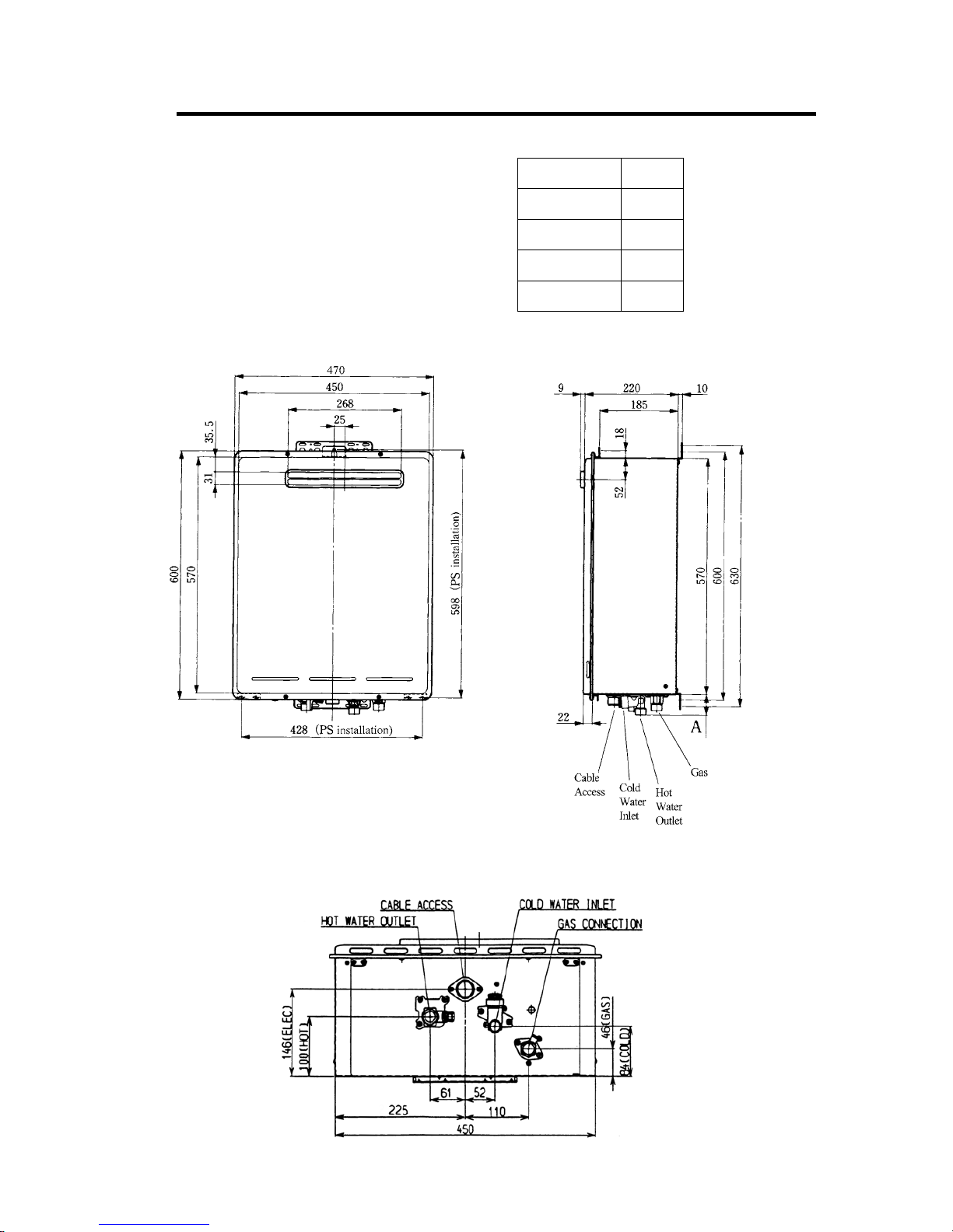
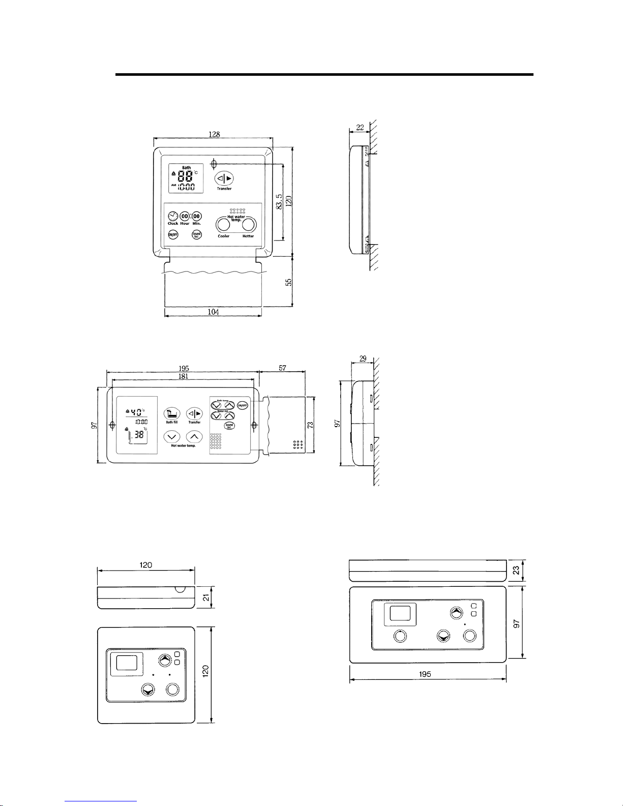
4. Dimensions
A
Gas 41
Cold Water 51
Hot Water 42
Power 27
Infinity REU-3203W - 8 - ©Rinnai
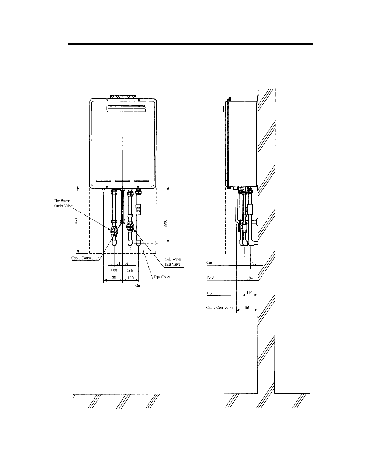
5. Installation
External Wall Installation
Important:
Refer to the current versions
of AG601/AS5601 and
AS3500 for installation
requirements.
Infinity REU-3203W - 9 - ©Rinnai
6. Remote Controls
Deluxe Kitchen Remote Control (MC-70)
Deluxe Bathroom Remote Control (BC-70)
Standard Kitchen Standard Bathroom
R e m o t e C o n t r o l R emote Control
(MC-33) (BC-45, BSC-45
Infinity REU-3203W - 10 - ©Rinnai
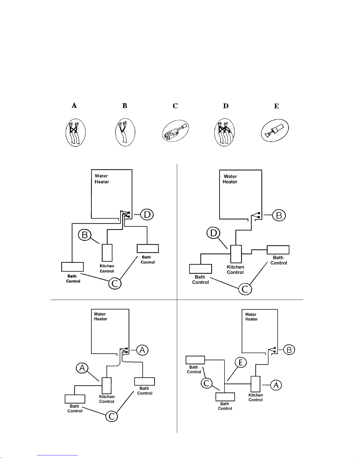
Remote Controller Connection
Remote Controllers operate on 12V DC supplied from the Infinity Printed Circuit Board. Controllers
are supplied with 15 metres of cable and connections. If more cable is needed, any two core cable
with similar specification can be used. Maximum cable length is 50m. Polarity does not need to be
considered when connecting controllers. Either colour wire can be connected to either terminal at
both the Infinity or the controller.
There must be at least one cable from any remote control connecting with the Infinity water heater.
Connections
The following diagrams show methods of connection.
Infinity REU-3203W - 11 - ©Rinnai
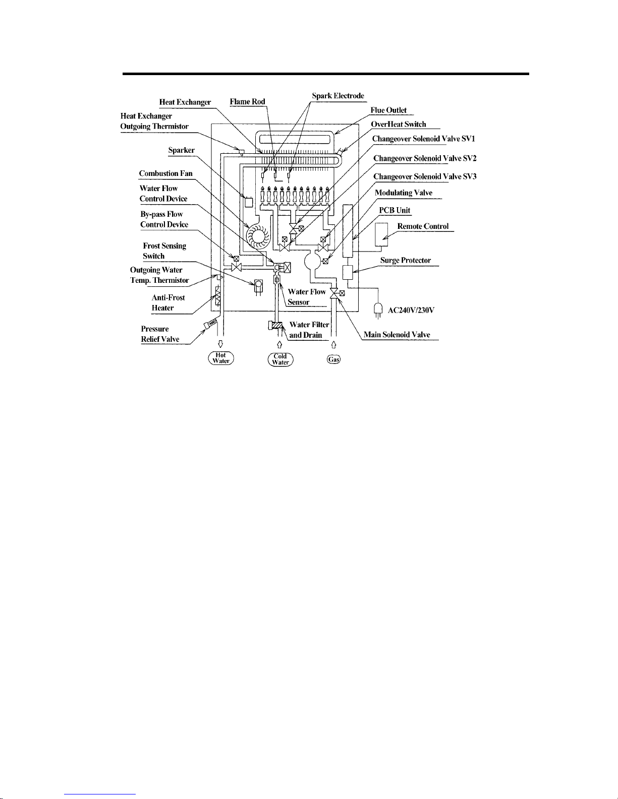
7. Cutaway Diagram
Infinity REU-3203W - 12 - ©Rinnai
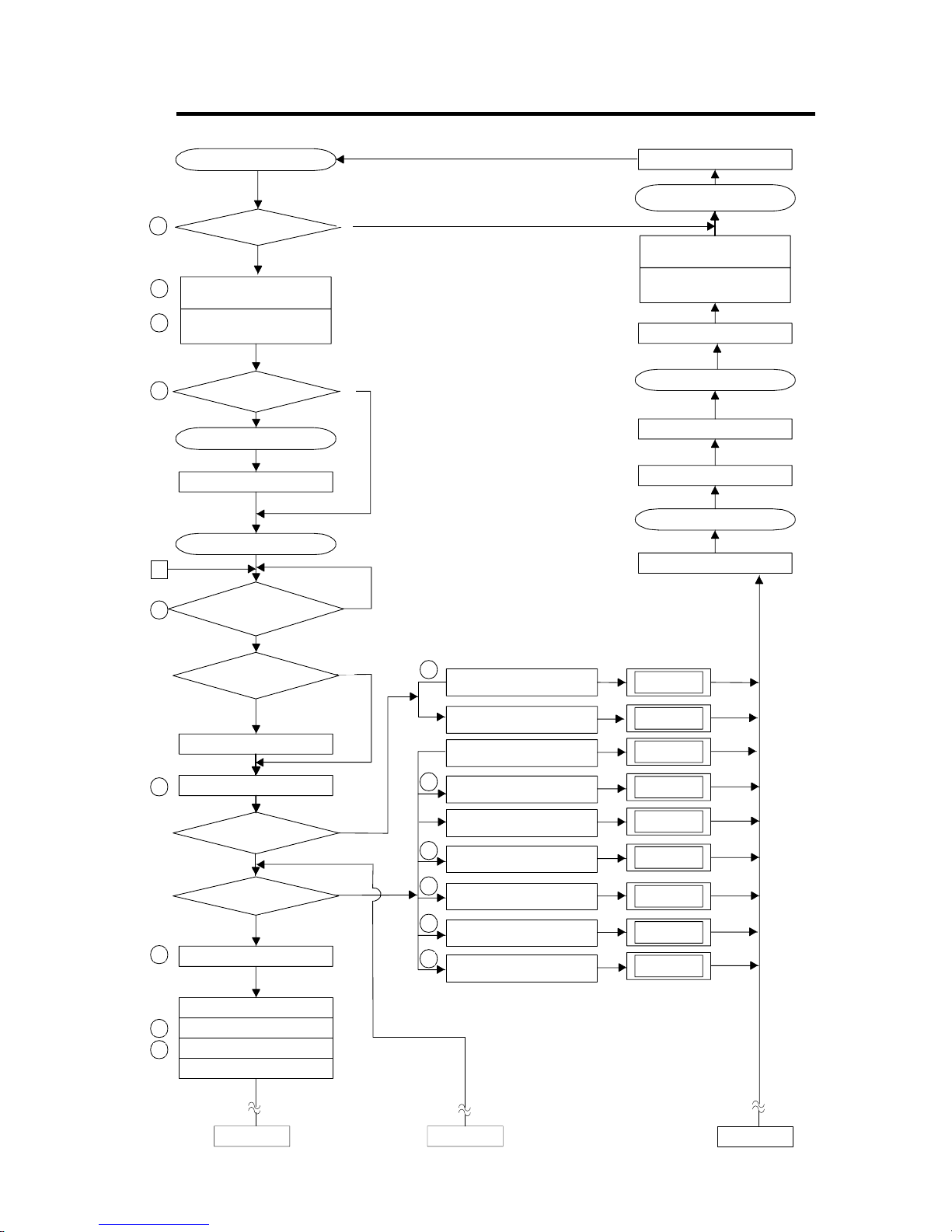
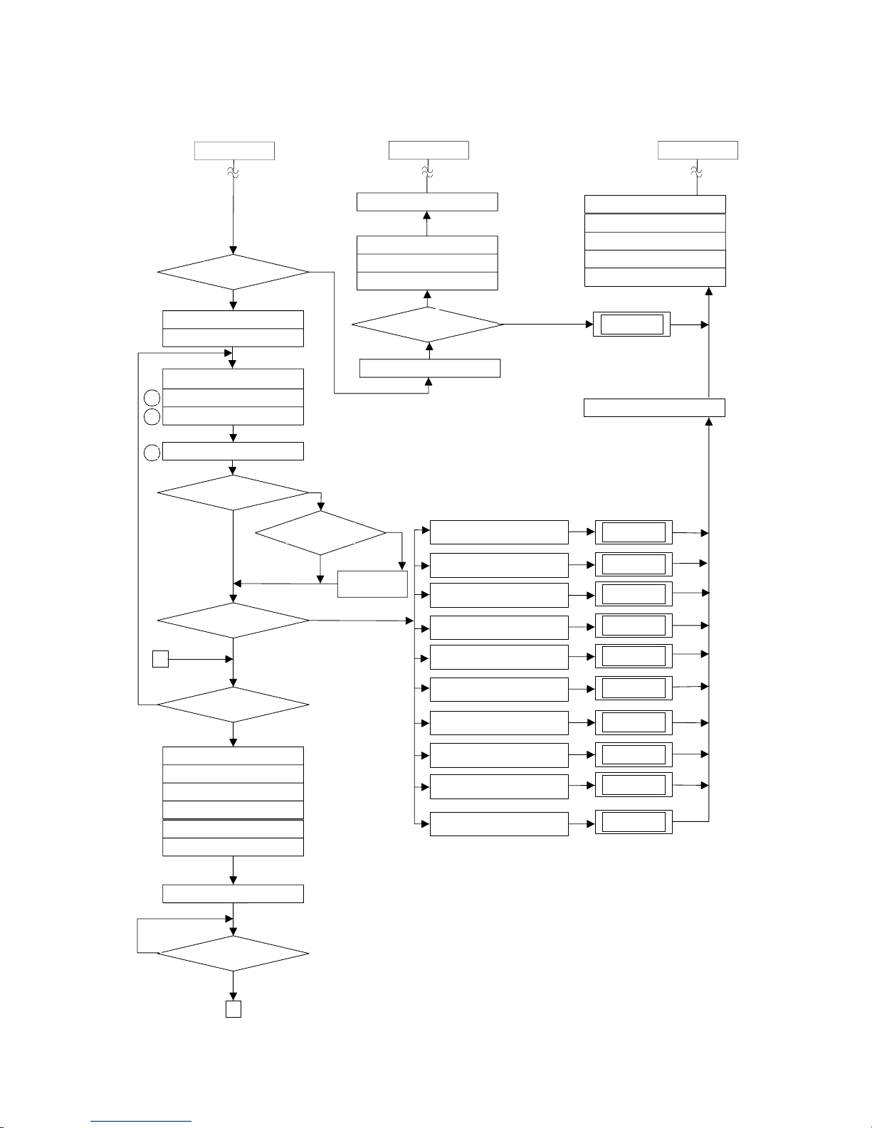
8. Operational Flow Chart
Bypass flow control device
full y open
Insert power plug
Safety device normal
ON/OFF switch ON
Remote control normal
ON/OFF indicat or ON
Hot water tap open
Water flow sens or ON
2.7 L/min or more
Set HW temp
50°C or more
Bypass control cl osed
Combustion fan ON
Fan rotaion
detected normal
Initial check normal
Sparker ON
Water flow control device
full y open
YES
YES
NO
YES
NO
Fan revolves for ignition
Main solenoid valve ON
Solenoid valve 1 ON
Modul ating va lve ON
Cause eliminated
Remove power plug from socket
Water flow control device
fully open
Bypas s flow co ntrol device
fully open
ON/OFF indicat or OFF
ON/OFF switch OFF
Error code indicator OFF
Water flow sens or OFF
Hot water tap closed
Combustion fan OFF
(after 5 seconds)
1
2
3
4
5
(a)
6
11
12
13
A
Control circuit short
False flame sensed
Solenoid valve circuit faulty
Modulating valve faulty
Outgoing thermistor faulty
HEX outgoing thermistor faulty
Thermal fuse activated
Overheat switch activ ated
Combustion fan rotation
abnormal (12.5 secs after (a))
Air supply and combustion air
duct blocked
61 flas hing
10 flas hing
12 flas hing
72 flas hing
71 flas hing
52 flas hing
32 flas hing
33 flas hing
14 flas hing
6
7
8
9
9
10
Hot water temp.
= fixed temp.
YES
NO
NO
YES
NO
NO
cont. next pagecont. next page cont. next page
YES
Infinity REU-3203W - 13 - ©Rinnai
A
12 flas hing
14 flas hing
16 flas hing
12 flas hing
32 flas hing
33 flas hing
52 flas hing
61 flas hing
71 flas hing
10 flas hing
Flame detected
(>1u A)
Combustion ind icator ON
Sparker OFF
Gas modulating control ON
Solenoid valve 2 ON
Solenoid valve 3 ON
Water flow control ON
Fan control normal
Auto. fan
revolut ion contr ol
Input down
operation
Safety de vice normal
HEX outgoi ng
temp. > 95°C
Main solenoid valve OFF
Solenoid valve 1 OFF
Solenoid valve 2 OFF
Solenoid valve 3 OFF
Modul ating va lve OFF
Combust ion indicat or OFF
Combust ion fan OFF
HEX outgoi ng
temp. < 60°C
(after 65 seconds)
NO
YES
YES
NO
YES
YES
NO
Max. fan revolution
(2 second s)
Solenoid valve 1 OFF
Main solenoid valve OFF
Modula ting valve OFF
Ignition failure
< 2 times
Sparker OFF
(after 4 secs)
Modul ating va lve OFF
Solenoid valv e 3 OFF
Solenoid valv e 2 OFF
Solenoid valv e 1 OFF
Main solenoid valve OFF
11 flas hing
Flame current abnormal
Thermal fuse activated
Outgoing water temperature
>105°C
Control circuit short
Outgoing thermistor faulty
HEX outgoing thermistor faulty
Modul ating va lve faul ty
Combustion fan rotation
abnormal
Solenoid valve c ircuit faulty
Combust ion faulty
Combusti on indicat or OFF
B
NO
YES
NO
14
15
16
from previous page
from previ ous page from pre vious page
YES
NO
NO
YES
Infinity REU-3203W - 14 - ©Rinnai
9. Operation Principles
Hot Water Operation
1. Ignition
• Activate controllers (if fitted) and open the hot water tap (for full details regarding operation of
controllers refer to the ‘How To Use Your Water Heater’ booklet).
• When water flows through the unit, the water flow sensor rotates and sends an electrical ‘pulse’
signal to the Printed Circuit Board (PCB). This signal is proportional to the water flow rate.
• The PCB sends electrical current to the combustion fan motor causing it to turn. The fan motor
sends an electrical pulse signal to the PCB. If fan rotation is OK, the main solenoid and
changeover solenoid valves open as required, the spark generator activates and the spark
electrode ignites the burner.
2. Water Temperature / Flow Control / Volume Control
• The PCB will automatically control operation of the internal components to achieve the
programmed temperature. When a high temperature rise is required, the PCB may cause the
Water Flow Servo to close partially resulting in a lower flow rate to achieve the programmed
temperature. This is a necessary operational feature of the unit.
• When operating in ‘Bath Fill’ mode, the signal from the water flow sensor is also used by the
PCB to compute the volume of water that has been passed through the unit at any instant whilst
the bath is filling.
3. Shut Down
• When operating in ‘Bath Fill’ mode, the PCB causes the Water Flow Servo to close when the
programmed Bath Fill volume has passed through the unit. Alternatively, flow is stopped when
the user closes the hot water tap.
• When water flow stops, the water flow sensor stops rotating and the pulse signal to the PCB
stops. The PCB then causes the main solenoid and solenoid valves to close and the burner is
extinguished. The combustion fan will continue to operate for some time to purge the
combustion chamber.

Infinity REU-3203W - 15 - ©Rinnai
10. Main Components
1) Printer Circuit Board
• The Printed Circuit Board controls all operational functions including Air Supply Control, Gas
Control, Water Flow Measurement, Water Flow Control, Combustion System and all sensors and
safety devices.
2) Gas Flow Control
• During normal operation, the PCB keeps the main solenoid valve open whilst there is flow
through the unit and the burner needs to be lit.
• Gas flow rate is controlled by the modulating valve assembly and three changeover solenoid
valves to always ensure constant outlet water temperature, regardless of flow rate or incoming
water temperature.
• The modulating valve is electronically controlled by the PCB using signals from the water flow
sensor, water flow control device, bypass flow control device, water temperature thermistors and
combustion fan speed sensor. The modulating valve directs gas to the three changeover solenoid
valves.
• The three changeover solenoid valves direct gas to each of the three burner banks independantly.
Any one, two or all of the solenoid valves may be open during operation.
• Gas flow is modulated between 20 and 250MJ/hr by a combination of the modulating valve and
changeover solenoid positions.
• The maximum gas rate is predetermined and the appliance cannot be overloaded when correctly
installed.
3) Water Flow Control
• Water flow is detected by a turbine coupled to a magnetic pulse generating device. The magnetic
pulses are detected and counted by the PCB. The PCB calculates the exact water flow from the
frequency of pulses generated by the turbine, as well as the volume of water that has passed
through the unit at any instant during ‘Bath Fill’ operation. A minimum flow rate of 2.7l/min. is
required for the burner to ignite.
• Water flow control is achieved through the use of servo driven water flow and bypass valves. Both
servo motors are controlled by the PCB. The ‘Water Flow Valve’ restricts the flow of water into
the heat exchanger assembly if the programmed temperature cannot be achieved. Also, when the
Bath Fill function is activated, flow of water is stopped when the bath is full. During normal
operation, cold water from the inlet valve is mixed with hot water from the heat exchanger outlet.
The ‘Bypass Valve’ mixes the correct proportion of cold and hot water to ensure accurate hot
water delivery temperature over the available range of flow rates. The water flow and bypass
valves are a combined assembly on the cold water inlet of the appliance.
4) Air Supply Control
• Air for combustion is supplied by a centrifugal fan driven by a variable speed DC motor. The
voltage to the motor is determined by the PCB based on water flow, delivered water temperature
and programmed water temperature. The actual fan speed is monitored by a magnetic pulse
counter. This counter emits a signal to the PCB. From the voltage supplied to the DC motor and
the fan speed signal, the PCB determines whether an error condition exists with the fan.
5) Combustion System
The combustion chamber is housed within the heat exchanger assembly and comprises:
• A three chamber aluminium alloy manifold with a total of 44 integral injectors, arranged in two
rows of twenty two. The middle chamber houses eight injectors, the left chamber, twelve, and the
right chamber, twenty four injectors. Gas flow to each chamber is controlled by an electronic
solenoid valve (refer ‘Gas Flow Control’ above).
• A burner assembly comprising twenty two identical modular stainless steel bunsen burners
secured by an aluminised steel framework. The manifold is attached to the front of the burner
module. Each bunsen burner is supplied by two injectors.
• A combustion chamber. Integrated into the combustion chamber front panel are the flame rod
and two ignition electrodes.
 Loading...