

Page 1
21. Fault Diagnosis
Before carrying out checks marked #, remove power cord from wall plug.
Wiring diagram is o n pag e 35.
Appliance will to operate (even remote control fails to operate)
1) Is the fuse blown?
Check fuse
a. Remove 240V plug from socket.
b. # Measure resistance to check the electric
Fuses are located in plastic holders in
the main harness, on the lower right
hand side of the appliance
fuse (3A).
Normal: less than 1
If normal, proceed to check item 2) below.
Faulty: Replace fuse (5A)
If it blows again, investigate cause of short
circuit.
Ω
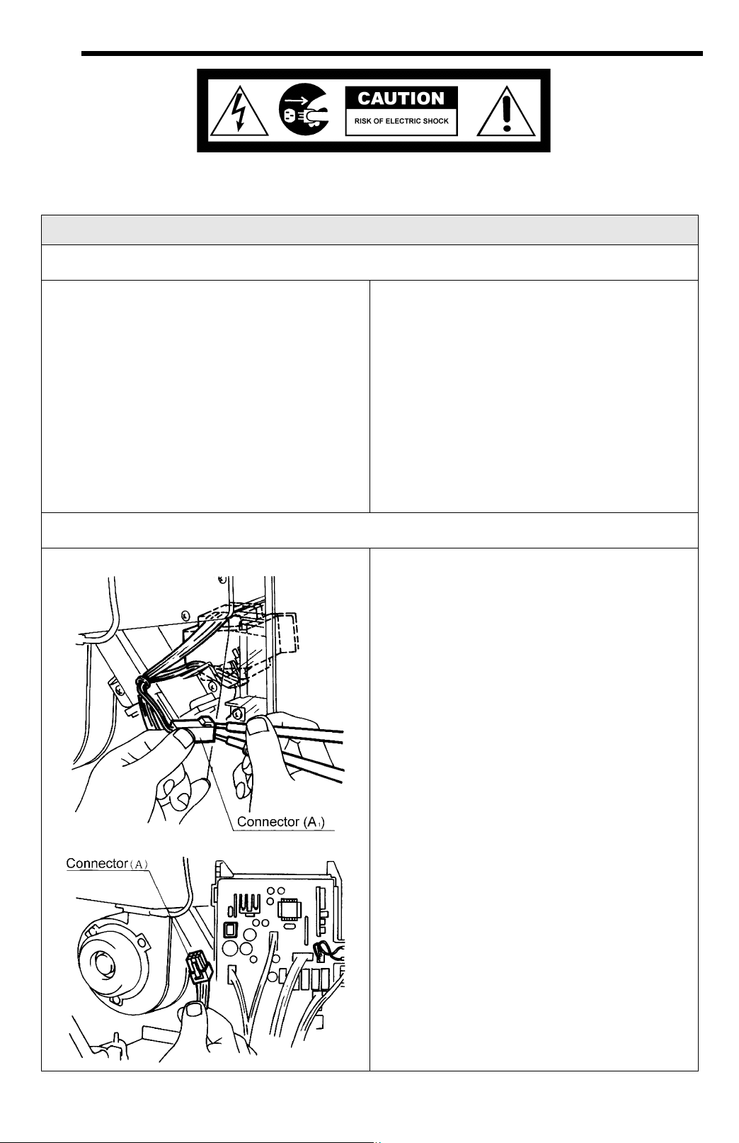
2) Is the main transformer normal?
Check the transformer.
a. Measure the voltage in between the red
wires of the relay connector (A
Normal: AC90 ~ 110 V / 15 ~ 21
If normal, check 2 below.
Faulty: Check for AC 90 ~ 110 V on the
PCB terminal J
black ~ black
b. Check voltages below at upper PCB
connector A.
Normal: orange -orange
AC 13 ~ 30V / 1.4 ~ 1.8
brown - grey
AC 30 ~ 50V / 6 ~10
yellow - grey
AC 180 ~ 220V / 0.4 ~ 0.6
If normal, check 3 at top of next page.
Faulty: Replace the transformer.
Ω
Ω
Ω
).
1
Ω
E
-
-
-
Page 2
c. Check the voltage at centre PCB connector
F, green~green.
Refer to diagram on
bottom of previous page.
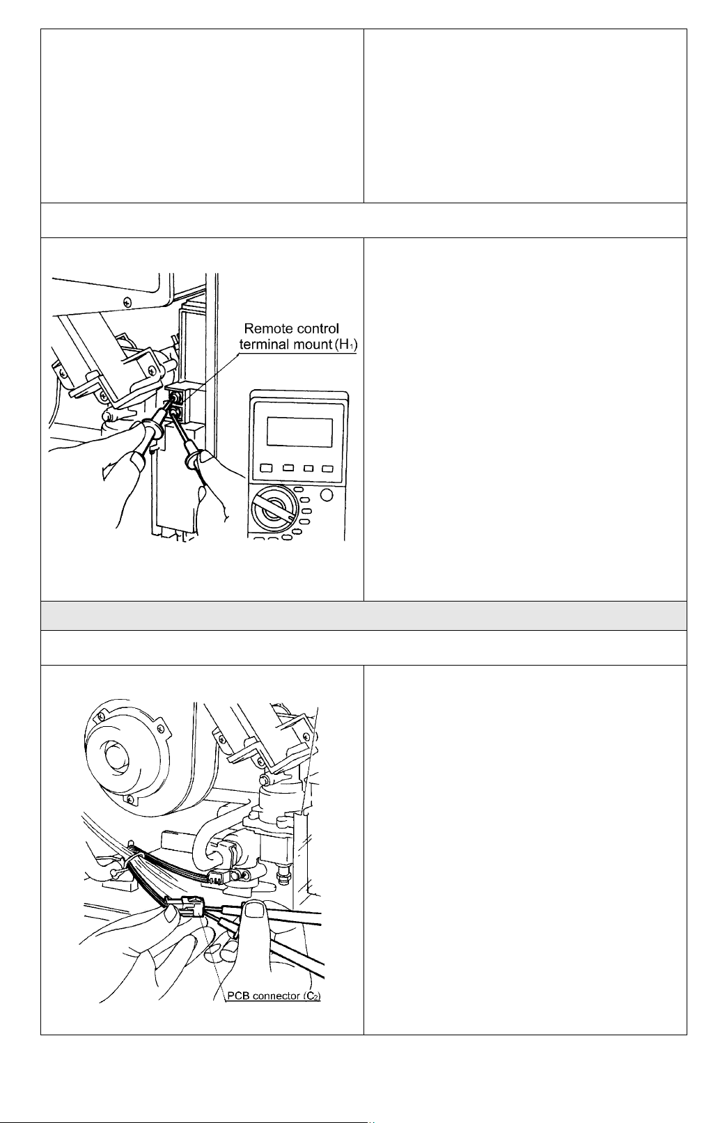
3) Is the remote control normal?
Normal: AC 16 ~ 20V
If normal, check item 3) below.
Faulty: Replace the transformer.
Note: Transformer voltage above applies
to the appliance in a standby, nonfunctioning state.
Check voltage between the two remote
control cable conductors.
a. Check the voltage between terminals on
the remote control terminal mount (H
Normal: DC 10 ~ 13V
If normal, check for open circuit or
shorts before replacing the remote
control.
Faulty: Replace PCB.
).
1
No combustion (despite remote control indication)
1) Is the water flow sensor normal?
a. Measure the voltage between red and
black of the relay connector (a
).
2
Normal: DC 11 ~ 13V
If normal, go to (b).
Faulty: Replace water flow control.
b. Measure the voltage between yellow and
black of the relay connector (a
)
2
Normal: DC 2 ~ 10V
If normal, go to 2).
Faulty: Replace the water flow sensor.
E
-
-
-
Page 3
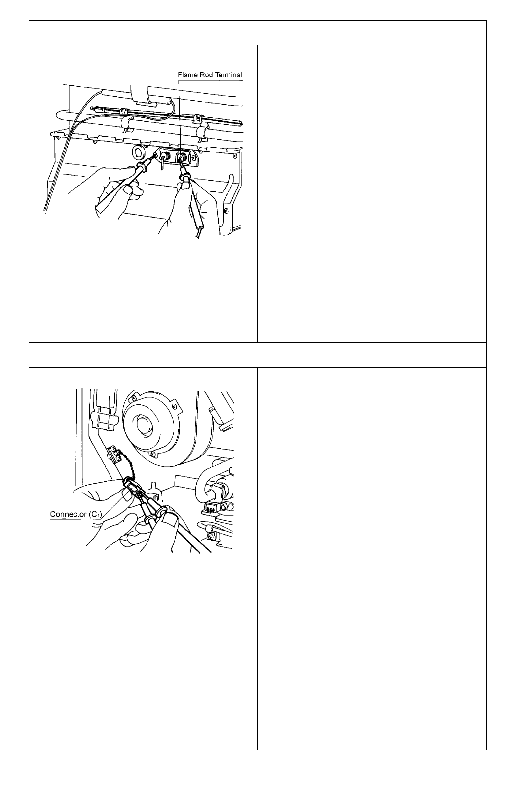
2) Is the flame rod normal? Error “72” is displayed
Checking the flame rod.
3) Is the water temperature thermistor normal?
a. # Detach the flame rod terminal A
re-attempt operation.
(“72” is displayed)
Proceed to check item 3) below.
(“72” is not displayed)
Inspect for electrical current leak from
the flame rod.
Measure resistance between flame rod
terminal A
Normal: 1 M or more
and the appliance earth.
2
Ω
If normal, replace the PCB unit.
Faulty: Replace the flame rod.
, and
2
If error “32” is displayed, check the water
temperature thermistor.
a. # Disconnect connector C
, and measure
1
the resistance of white and white.
Resistance > 1M = open circuit.
Resistance < below 1 = short circuit.
Ω
Ω
Normal: proceed to check item 4.) on next
page.
Faulty: replace the water temperature
thermistor.
E
-
-
-
Page 4

4) Is the combustion fan normal?
Motor check
If error “61” is displayed, check
combustion fan.
a. Measure the voltage at the connector (D
black ~ red
Normal: DC 6~40V (fan on)
DC 0V (fan off)
If normal, go (b)
Faulty: Replace the PCB unit
Fan Revolution Sensor Check
b. Measure the voltage at connector D
1
black ~ yellow
Normal: DC11~13V
If normal, go (b) below
Faulty: Replace the PCB unit
c. Measure the voltage at connector D
1
black ~ white
Normal: DC2~9V
If normal, proceed to check item 5)
below
Faulty: Replace the combustion fan.
)
1
,
,
5) Is the sparker operating normally?
Checking the motor
a. Measure the voltage at connector I
grey ~ grey
Normal: DC 90 ~ 110 V
DC 0 V (when fan is OFF)
If normal, check (b) below.
Faulty: Replace the PCB unit
b. # Disconnect I
, and measure the
4
resistance between sparker terminals
Normal: >1M
Ω
If there is no spark, adjust or replace the
electrode.
Faulty: Replace the sparker.
.
4
E
-
-
-
Page 5

6) Is main gas so lenoid valve (SV1) normal?
If error “11” is displayed, check the main gas
solenoid valve.
a. # Disconnect the main gas solenoid valve
(SV
), connector and measure the
1
resistance at the solenoid terminals.
Normal: 0.9 ~ 1.3 k
Ω
If normal, check (b) below.
Faulty: Replace the main gas solenoid
valve.
b. Measure voltage main gas solenoid valve
(SV
) pink ~ black connector.
2
Normal: DC80~100V
If normal, proceed to check item 7) below.
Faulty: Replace the PCB unit.
7) Is the change over solenoid (SV
) operating normally?
2
8) Is the change over solenoid valve (SV
) normal?
3
If error “11” is displayed, check the change
over solenoid valve (SV
).
2
a. # Disconnect the main gas solenoid valve
(SV
) connector, and measure the
2
resistance at the solenoid terminals.
Normal: 1.3 ~ 1.9 k .
Ω
If normal, check (b) below.
Faulty: Replace the change over solenoid
valve (SV
).
2
b. Measure voltage at change over solenoid
valve (SV
) blue ~ black connector.
3
Normal: DC 80 ~ 100V
If normal, check item 9) below.
Faulty: Replace the PCB unit
a. # Disconnect the change over solenoid
valve (SV
) connector, and measure the
3
resistance at the solenoid terminals.
Normal: 1.3 ~ 1.9 k
Ω
If normal, check (b) below.
Faulty: Replace the change over solenoid
valve (SV
).
3
b. Measure the voltage at changeover
solenoid valve (SV
) blue ~ black
3
connector.
Normal: DC 80 ~ 100V
If normal, check item 9).
Faulty: Replace the PCB unit.
E
-
-
-
Page 6

9) Are the safety devices operating normally?
Check the thermal fuse.
Combustion stops due to flame failure
1) Is the flame rod functioning normally?
a. # Disconnect connector B
and measure
2
the resistance between red ~ red.
Normal: less than 1 .
Ω
If normal, replace the PCB unit.
Faulty: Check the appliance for damage.
If there is nothing abnormal, replace the
thermal fuse.
Check the remaining flame safety device.
b. Measure resistance between the two
terminals B
Normal: less than 1
.
3
Ω
If normal, replace the PCB unit.
Faulty: Replace the remaining flame safety
device.
a. Measure the voltage between the flame
rod terminal (A
) and the appliance earth.
2
Normal: AC 100 ~ 160V
If normal, check (b) below.
Faulty: Replace the PCB unit.
2) Is the earth lead wire normal?
b. Check that the flame rod attachment is not
loose.
Normal: Replace the PCB unit
Faulty: Secure the flame rod brackets.
a. Check whether the earth lead wire has
come loose (disconnection from round
terminal) or if any shorts have occurred.
If normal, check for any other causes for
flame failure (eg. gas valve is open,
blocked filter, etc)
Faulty: Secure the earth.
E
-
-
-
Page 7

Unable to adjust hot water temperature
1) Is the water temperature thermistor normal?
a. Disconnect the connector (C
) and
1
measure the resistance between white
wires.
See diagnostic points, for temperature at
various resistance.
Normal: Proceed to check item 2) below
Faulty: Replace water temperature
thermistor.
2) Is the changeover solenoid valve (SV
) normal?
3
a. # Disconnect the changeover solenoid
valve (SV
) connector, and measure the
3
resistance between the solenoid terminals.
Normal: 1.3 ~ 1.9 k .
Ω
If normal, go to (b).
Faulty: Replace the changeover
solenoid valve (SV
).
3
b. Measure the voltage at the changeover
solenoid (SV3) blue ~ black connector.
Normal: DC 80 ~ 100V
If normal, go to item 3) on the next page.
Faulty: Replace the PCB unit.
E
-
-
-
Page 8

3) Is the modulating valve operating normal?
a. # Disconnect the modulating valve festoon
terminals and measure the resistance at the
terminals.
Normal: 60 ~ 100
Ω
If normal, go to (b.
Faulty: Replace the modulating valve.
b. Re-connect terminal and measure the pink
~ pink voltage at the modulating valve
festoon terminal.
Normal: DC 0.5 ~ 25 V
If normal, go to (c) below.
Faulty: Replace PCB unit.
c. Investigate the change in gas secondary
pressure when the remote control preset
temperature is altered from 37 to 75C.
°
Normal: If the secondary pressure
changes, proceed to check item 4) below.
Faulty: Replace the modulating valve.
4) Is the water flow servo normal? (2008/2408)
a. # Disconnect connector and measure the
red ~ blue resistance on the water flow
servo side.
Normal: 10 ~ 30
$
If normal, go to b.
Faulty: Replace the water flow servo with
water flow sensor.
b. Disconnect connector, and measure the
voltage between orange (+) and grey(-) on
the water flow control side.
Normal: DC 11 ~ 13 V
If normal, go to (c).
Faulty: Replace the PCB unit.
c. With connector (E
) connected (do not
1
turn water ON... wait for the water flow
servo to return to fully open), measure the
voltage between brown and grey.
Normal: DC 4 ~ 6V
Faulty: Change water flow servo with
sensor.
d. Leaving the relay connector (E
)
1
connected (do not turn water ON... wait for
the water flow servo to return to fully
open), measure the voltage between yellow
and grey.
Normal: Less than DC 0.5 V
Faulty: Change water flow servo with
sensor.
E
-
-
-
Page 9

Anti frost heater does not operate
1) Are the ceramic anti-frost heaters OK?
a. # Disconnect connector (J
) and measure
3
the blue and blue resistance on the water
control heater side.
Normal: 950~1050 (2424, 2408, 2008)
590 ~ 660 (2007)
Ω
Ω
If normal, go to (b).
Faulty: Replace the water control heater
(2424, 2408, 2008).
Replace the anti-frost heater D assy
(2007).
b. # Disconnect connector (J
) and measure
3
the resistance between blue and blue on
the heater exchanger’s heater side.
Normal: 135 ~ 175
Ω
If normal, go to item 2) below.
Faulty: Replace anti-frost heater (assy)
2) Is the frost sensing switch normal?
a. # Detach connector (J
) and measure the
2
resistance between blue and blue.
Measure at room temperatur e of 4 ± 3 C.*
Normal: Less than 1
Ω
if normal, check the wiring (AC100V
circuit)
Faulty: Replace the frost sensing switch.
*
Where the low room temperature cannot be
achieved, plea se cool with i ced wat er or cold
water below 4 C.
°
°
E
-
-
-
 Loading...