

Page 1
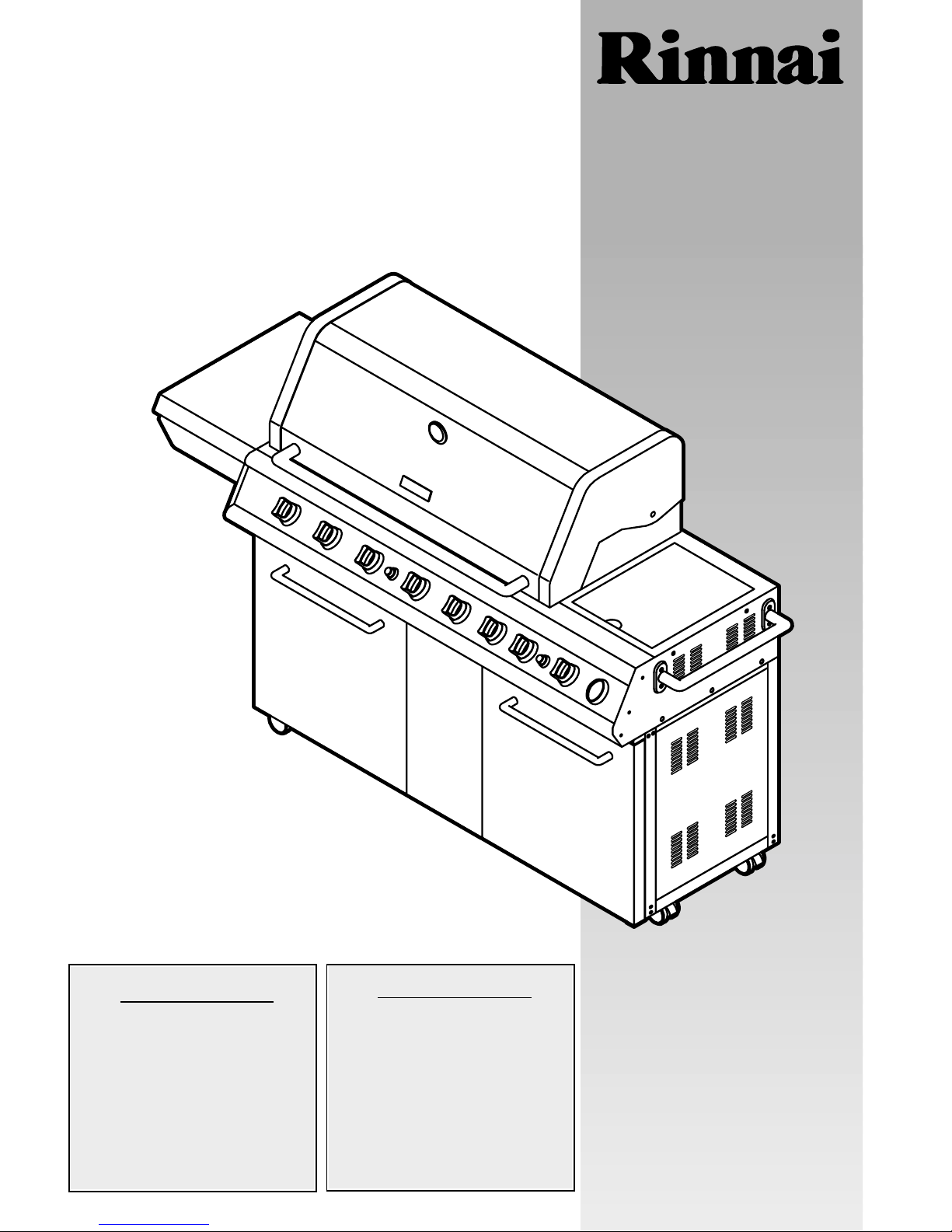
These instructions are a guide
to assembling and using the
Impressor 8 (Australia)
Elite (New Zealand)
barbecue.
Please read carefully, and
retain for future reference.
Only to be used outdoors.
Illustration may vary from barbecue
contained in carton.
FOR YOUR SAFETY.
1. Do not store or use
petrol or other flammable
vapours and liquids in the
vicinity of this or any other
appliance.
2. A gas cylinder not connected
for use must not be stored
in the vicinity of this or any
other appliance.
FOR YOUR SAFETY.
IF YOU SMELL GAS:
1. Shut off gas to the appliance.
2. Extinguish any open flame.
3. Open hood.
4. If odour continues,
immediately call your gas
supplier or fire department.
PART NO. P80140004A
Customer’s operating and assembly instructions
Page 2
GENERAL INFORMAT I O N
2
2
A guarantee explanation sheet is supplied separately
with your barbecue. If you are missing the guarantee
explanation sheet, please contact one of the offices listed
on the rear cover to request one to be sent to you.
GUARANTEE
You have just purchased a state of the art Outdoor
Barbecue Cooking System.
We understand your desire to protect an investment
of this nature. As such this booklet has been designed to
assist you in the assembling, testing and operating your
new barbecue, along with important safety information,
helpful maintenance tips and troubleshooting. We thank
you for choosing our product and trust that you enjoy
years of outdoors entertainment.
Happy Gourmet cooking!
CONGRATULATIONS
Purchased from
Date purchased
Serial No.
NOTE:
Sales docket must be kept as proof of purchase date.
FOR CUSTOMER REFERENCE
(Record and file in a safe place)
Inspect barbecue and trolley parts as you proceed.
Contact your place of purchase for assistance regarding
replacement of any damaged or missing parts. Do not
assemble or operate a barbecue that appears damaged.
Check that the barbecue supplied is correct for the gas
type being used. There is a label on the rear panel of the
barbecue.
Barbecues for use with gas cylinders are labelled
‘Universal LPG’. Barbecues for use with natural gas are
labelled
‘Natural Gas’.
Check that the label matches the gas type to be
used.
CHECK BARBECUE FOR ANY DAMAGE
PARTS SUPPLIED SEALED IN THE
CARTON, OR BY YOUR PLACE OF
PURCHASE, MUST NOT BE ALTERED
IN ANY WAY.
!
NATURAL GAS BARBECUES
MUST BE INSTALLED BY AN
AUTHORISED PERSON.
!
While it is possible for one person to assemble the
barbecue, we recommend asking for the assistance of
another person when manoeuvring some of the larger
or heavier pieces.
Remove the barbecue and its components from the
carton. Check against parts list and lay components out
within easy reach. Do not throw the shipping carton
away – unfold flat and use as a protective work surface.
Contact your place of purchase for replacement parts if
necessary.
GENERAL
Standard Phillips-head screwdriver.
Adjustable spanner
(open end shifter).
TOOLS YOU WILL NEED
General Information 2-3
Safety Instructions 4
Pre-Assembly Instructions 5-7
Assembly Instructions 8-15
Operation Instructions 16-18
Fault Finding 19
Cleaning and Maintenance Instructions 20-21
Outdoor Areas 22
Contact Points 23-24
TABLE OF CONTENTS
1. Flatten cardboard packaging and use this as a
protective work surface to assemble upon.
2. Some protective coating may need to be removed
from components prior to assembly.
3. Do not tighten screws and nuts until trolley is fully
assembled.
4. Pre-screwing of connection points for securing the
side shelves will assist in securing shelves smoothly.
ASSEMBLY TIPS
Page 3
GENERAL INFORMAT I O N
3
3
The following minimum clearances from combustible
materials must be maintained: Top – 1000 mm, rear –
450 mm and sides – 250 mm.
Openings at the rear and sides of the appliance
provide air for combustion, and must not be obstructed.
CLEARANCES
Height – Hood closed 1260 mm.
Hood open 1510 mm.
Width – 1900 mm
Depth – Hood closed 655 mm.
– Hood open 725 mm.
OVERALL DIMENSIONS
Australian Gas Association Certificate No. 6468.
Barbecues must be used in accordance with the
installation requirements of your local gas supply
authority, and the appropriate installation standard
AS5601/AG601.
Barbecues for use with cylinder gas are labelled
‘Universal LPG’. Barbecues for use with natural gas
are labelled
‘Natural Gas’ and must be installed by an
authorised person. Check the gas type sticker attached
to the barbecue. Check that the label matches the gas
type to be used.
GAS INSTALLATION CODES HOSE AND REGULATOR SAFETY
NEVER OPERATE THIS BARBECUE
WITHOUT A REGULATOR.
!
FAILURE TO COMPLY WITH THESE
INSTRUCTIONS COULD RESULT IN A
FIRE OR EXPLOSION WHICH COULD
CAUSE SERIOUS BODILY INJURY,
DEATH OR PROPERTY DAMAGE.
!
ACCESSIBLE PARTS MAY BE VERY HOT.
KEEP YOUNG CHILDREN AWAY.
ANY MODIFICATION OF THIS
APPLIANCE MAY BE DANGEROUS.
DO NOT MOVE THIS APPLIANCE
DURING USE.
TURN OFF THE GAS SUPPLY AT THE
GAS CYLINDER AFTER USE.
READ THE INSTRUCTIONS BEFORE
USING THE APPLIANCE.
PARTS SEALED BY THE
MANUFACTURER MUST NOT BE
MANIPULATED.
THIS BARBECUE IS ONLY TO BE USED
AND STORED OUTDOORS.
!
The regulator and hose assembly supplied with the
barbecue is suitable for use with bottled gas.
A gas regulator adjusted to have an outlet pressure
of 2.75 kPa is supplied for connection to the gas cylinder.
The regulator and hose assembly supplied with the
appliance must be used. Replacement regulator and
hose assemblies must be those specified by the appliance manufacturer.
When connecting the hose and regulator assembly
to the gas cylinder, take care to avoid unnecessary
twisting of the flexible hose. After the assembly has
been secured, turn on the gas and check for leaks by
brushing a soap and water solution over all visible and
accessible gas line connections. The presence of bubbles
will indicate a gas escape.
DO NOT TEST FOR GAS
ESCAPES WITH AN OPEN FLAME.
If you are unable to correct the leak by tightening
the connection, turn off the gas and contact your place
of purchase immediately.
Always ensure the appliance is kept away from
flammable materials and the gas cylinder clear of any
heat source.
When changing over from an empty gas cylinder to
a full one, make sure this procedure is carried out in a
flame free atmosphere.
Inspect the gas hose when replacing the gas cylinder
or once a year whichever is more frequent. If the hose
is cracked, cut, abraded or damaged in any way, the
appliance must not be operated. The hose must be
replaced if damaged or when statutory conditions
require it. Contact your place of purchase if uncertain.
The POL fitting of the hose and regulator should be
disconnected from the gas cylinder valve when the
outdoor appliance is not in use.
Appliance specifications can be found on the data label
attached to the rear panel of the barbecue body.
Your barbecue is preset at the factory to operate on
bottled gas only, unless specified otherwise.
SPECIFICATIONS
GAS HOSES ARE FACTORY FITTED AND
LEAK TESTED – DO NOT DISCONNECT.
!
Page 4
SAFETY
4
4
FOR YOUR SAFETY:
DO NOT STORE OR USE PETROL OR
OTHER FLAMMABLE VAPOURS AND
LIQUIDS IN THE VICINITY OF THIS OR
ANY OTHER APPLIANCE.
DO NOT STORE EMPTY OR FULL SPARE
GAS CYLINDERS IN STORAGE
COMPARTMENT OR NEAR THIS OR ANY
OTHER APPLIANCE.
KEEP THE GAS HOSE AWAY FROM HOT
SURFACES. PROTECT GAS HOSE FROM
DRIPPING GREASE.
AVOID UNNECESSARY TWISTING OF
HOSE. VISUALLY INSPECT HOSE PRIOR
TO EACH USE FOR CUTS, CRACKS,
EXCESSIVE WEAR OR OTHER DAMAGE.
REPLACE HOSE, IF NECESSARY.
NEVER TEST FOR GAS LEAKS WITH A LIT
MATCH OR OPEN FLAME.
NEVER LIGHT BARBECUE WITH HOOD
CLOSED.
NEVER LEAN OVER COOKING
SURFACE WHILE LIGHTING BARBECUE.
USE GOOD QUALITY INSULATED OVEN
MITTS WHEN OPERATING BARBECUE.
NEVER ALTER OR MODIFY THE
REGULATOR OR GAS SUPPLY ASSEMBLY.
THIS BARBECUE MUST NOT BE USED
INDOORS.
!
DANGER – IF YOU SMELL OR HEAR THE
HISS OF ESCAPING GAS FROM THE GAS
CYLINDER:
KEEP CLEAR OF THE GAS CYLINDER.
DO NOT ATTEMPT TO CORRECT THE
PROBLEM YOURSELF.
CALL YOUR FIRE DEPARTMENT
(DO NOT MAKE THE CALL FROM
ANYWHERE NEAR THE GAS CYLINDER –
YOUR TELEPHONE IS AN ELECTRICAL
DEVICE, AND COULD PRODUCE A SPARK).
!
READ CAREFULLY BEFORE
ASSEMBLING AND OPERATING
YOUR BARBECUE.
!
NEVER CONNECT AN UNREGULATED
GAS CYLINDER TO YOUR BARBECUE.
!
NEVER STORE YOUR GAS
CYLINDER INDOORS
FOR STORAGE AND CYLINDER
EXCHANGE, DISCONNECT HOSE AT
THE CYLINDER ONLY – DO NOT
DISCONNECT HOSE FROM
THE APPLIANCE.
!
DO NOT use your barbecue in garages, porches, breezeways,
sheds or other enclosed areas. Your barbecue is to be used
OUTDOORS ONLY. Refer to page 22. The barbecue is not
intended to be installed in or on recreational vehicles
and/or boats and should not be placed under any surface
that will burn. Do not obstruct the flow of combustion and
ventilation air around the barbecue while in use.
LOCATION OF YOUR BARBECUE
Keep children away from barbecue during use and until
barbecue has cooled after you are finished. Do not allow
children to operate barbecue, or to swing on handle.
PROTECT CHILDREN
NEVER TEST FOR LEAKS WITH AN OPEN FLAME.
Prior to first use, and at the beginning of each new season
(or, if using bottled gas, whenever gas cylinder is changed), you
must check for gas leaks.
Follow these steps:
1. Make soap solution by mixing one part liquid detergent
and one part water.
2. Turn burner control(s) to
‘OFF’, then turn on gas at
source.
3. Apply the soap solution to all visible and accessible
gas connections. Bubbles will appear in the soap
solution if connections are not properly sealed.
Tighten or rectify as necessary.
4. If you have a gas leak you cannot rectify, turn off the
gas at the source, disconnect hose from barbecue
and immediately contact the manufacturer for
assistance.
Refer to back cover.
CHECKING FOR GAS LEAKS
The gas cylinder should be filled by a reputable gas dealer,
or exchanged at a reputable cylinder exchange outlet. Gas
cylinders should be visually inspected and requalified
periodically.
Always keep gas cylinder in an upright position.
Always close the cylinder valve when the barbecue is not in use.
Do not subject gas cylinder to excessive heat.
If you store your barbecue indoors, ALWAYS disconnect
and remove gas cylinder FIRST, and store gas cylinder
safely outside. Gas cylinders must be stored outdoors in
a well ventilated area out of reach of children, and must not
be stored in a building, garage or any other enclosed area.
This is a low pressure barbecue and must only be used with
the hose and regulator supplied.
Your barbecue is designed for use with a 9 kg gas
cylinder. Ensure gas cylinder conforms to Australian
standards.
DO NOT CONNECT YOUR BARBECUE TO A GAS
CYLINDER LESS THAN OR EXCEEDING THIS CAPACITY.
GAS CYLINDER USE AND SAFETY
IF YOU SMELL GAS:
1. SHUT OFF GAS TO THE APPLIANCE
AT ITS SOURCE, IF POSSIBLE.
2. EXTINGUISH ANY OPEN FLAME.
3. OPEN HOOD.
4. PERFORM GAS LEAK CHECK
PROCEDURE.
5. IF ODOUR CONTINUES,
IMMEDIATELY CALL YOUR GAS
SUPPLIER OR FIRE DEPARTMENT.
!
Page 5
6
8
10
12
24
25
35
18
23
14
19
74
39
13
13a
22
29
28
30
17a
32
33
38
17b
59
75
75
54
47
52
43
40
44
64
63
65
66
57
58
56
55b
55a
34
37
62
20
21
42
36
27
9b
9a
26
11
71
16
15
45
49
53
61
50
46
51
69
48
41
60
68
70
31
42
1
3
5
7
67
72 (LPG only)
73 (LPG only)
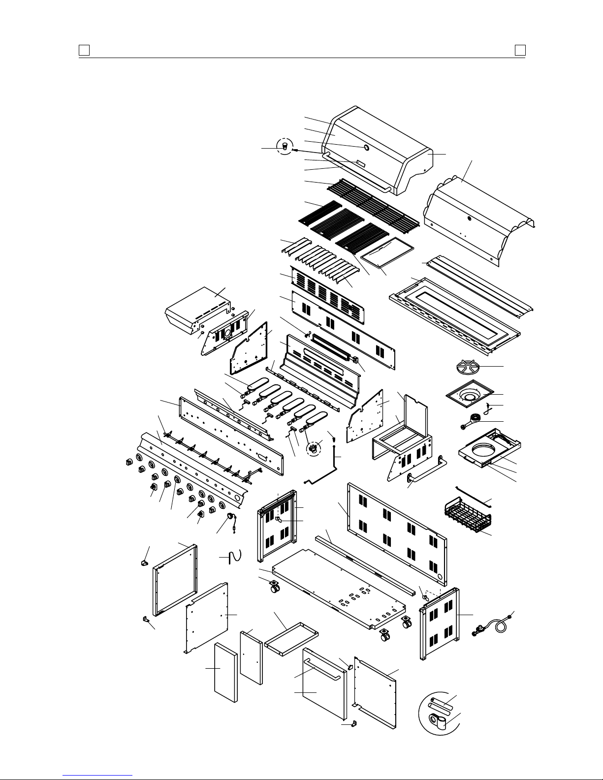
PARTS DIAGRAM
5
5
This diagram is provided to assist you
identify parts if replacement is necessary.
Contact your place of purchase or the
manufacturer to enquire about parts,
availability and or service.
Page 6

PARTS LIST
6
6
1
2
3
4
5
6
7
8
9a
9b
10
11
12
13
13a
14
15
16
17a
17b
18
19
20
21
22
23
24
25
26
27
28
29
30
31
32
33
34
35
36
36a
Stainless steel hood
Stainless steel hood trim plate
Hood side panel –
left
Hood side panel – right
Temperature gauge
Hood handle
Badge
S/S secondary cooking rack
Stainless steel cooking grid
C/I hotplate ceramic coating
Stainless steel cooking grid –
4"
Stainless steel flametamer
Stainless steel flametamer –
4"
Main burner
Air shutter for main burner
Main burner bracket
Gas collector box w/ electrode
Ignition wire set
Electric igniter –
4 ports
Electric igniter – 2 ports
Barbecue body panel – left
External body trim panel – left
Barbecue body panel – right
External body trim panel – right
Barbecue body panel – front
Barbecue body panel – rear
Wind shield – A
Wind shield – B
Pull-out grease draining tray and
2 x winged screws
Grease draining tray heat shield
Gas manifold/valve assembly
LPG
NG
Control panel heat shield
Control panel
LPG
NG (no fuel gauge hole)
Hood stopper
Control knob
Control knob seat
Rotisserie burner assembly
Electrode for rotisserie burner
Injector for rotisserie burner
LPG
NG
Injector for main burner
LPG
NG
P00117356A
P0011435EA
P00105347U
P00106347U
P00601171B
P00205033B
P00415006C
P01518028B
P01606030B
P05702004E
P01606031B
P01708031B
P01708032B
P02001050E
P05524137C
P02206271B
P02608050C
P02615053A
P02502024C
P02502012C
P00720291A
P00742296C
P00721291A
P00743296C
P00738304A
P00725304A
P00737309A
P06905006E
P02714291A
P06903009A
Y0060087
Y0060090
P03011132C
P02911291N
P02911291T
P05518100I
P03412331C
P03415264A
P02007049D
P02614006B
P06509010A
P06509012A
P06509011A
P06506002A
1
1
1
1
1
1
1
1
2
1
1
2
1
6
6
1
3
1
1
1
1
1
1
1
1
1
1
1
1
1
1
1
1
1
1
2
7
8
1
1
1
1
1
1
36b
37
38
39
40
41
42
43
44
45
46
47
48
49
50
51
52
53
54
55a
55b
56
57
58
59
60
61
62
63
64
65
66
67
68
69
70
71
72
73
74
75
----
----
Injector for side burner
LPG
NG
Gas tube for rotisserie burner
Control knob for rotiserrie burner
Side shelf – left
Trolley side handle
Bottom shelf
Trolley side panel –
left
Trolley side panel – right
Trolley rear panel
Door bracket
Door panel –
left
Door panel – right
Door trim plate – left
Door trim plate – right
Door axle bracket – left top
Door axle bracket – left bottom
Door axle bracket – right top
Door axle bracket – right bottom
Stainless steel door handle
Wire basket
Division wire for wire basket
Cylinder pull-out tray
– LPG only
Bracket for cylinder pull-out tray
LPG only
Cylinder tray slide
Fuel gauge display with stainless
steel ring assembly –
LPG only
Castor
Manual lighting stick
Stainless steel side burner lid
S/S side burner body –
inner
Pot support
Side burner electrode
Side burner assembly
Regulator and hose assembly
Division panel
Decorative panel
Decorative inside panel
Heat-insulating ring for main
burner valve
AAA battery –
LPG fuel gauge
Wire fastener – LPG only
Side shelf nylon insulating spacers
Winged screws (inc. hardware pack)
Hardware pack
Operating and assembly
instruction booklet
P06522001A
P06522002A
P03717033A
P03412341C
P01106028B
P00205032B
P01005027K
P07617009E
P07618009E
P07702018E
P03301022J
P04302012A
P04303012A
P07506007D
P07507007D
P03314018C
P03314019C
P03314020C
P03314021C
P00205036B
P05204010E
P05204012E
P04009028H
P04010030H
P05516131B
P05310032B
P05115020A
P05313023B
P00115346A
P02301006B
P00805013B
P02607052C
P02002056D
P03603001A
P07512013D
P07501008A
P07509009D
P06801007F
P05301002A
P05310040A
n/a
n/a
P06001028A
P80140004A
1
1
1
1
1
1
1
1
1
1
1
1
1
1
1
1
1
1
1
2
1
1
1
1
1
1
4
1
1
1
1
1
1
1
1
1
1
6
2
1
4
2
1
1
Ref. Description Part No. Qty Ref. Description Part No. Qty
Page 7
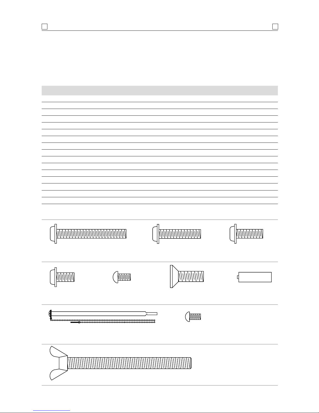
1/4"x30 mm Phillips-head screw
Qty. 6 Ref. # H032
1
/4" x 3/4" Phillips-head screw
Qty. 4 Ref. # H031
1
/4" x 3/4" flat-head screw
Qty. 4 Ref. # H034
M4 x 8 mm Phillips-head screw
Qty. 1 Ref. # H035
3
/16"x 9 mm Phillips-head screw
Qty. 8 Ref. # H033
1
/4" x 1/2" Phillips-head screw
Qty. 38 Ref. # H005
1
/4" x 50 mm Phillips-head screw
Qty. 12 Ref. # H030
Manual lighting stick
Qty. 1 Ref. # P05313023B Scale 1:2
5
/16" x 89 mm wing bolt (LPG model only) Qty. 1 Ref. # H029
AA battery Qty. 2
Ref. # P05301001A Scale 1:2
PARTS LIST
7
7
The following information is a breakdown of the hardware pack.
It explains which fittings are used during the various stages of assembly.
H005
1
/4" x 1/2" Phillips-head screw 16 Install castor to castor seats of bottom shelf
H030
1
/4" x 50 mm Phillips-head screw 8 Attach trolley side panels to bottom shelf
H005
1
/4" x 1/2" Phillips-head screw 8 Attach rear panel to trolley
H005
1
/4" x 1/2" Phillips-head screw 4
Attach cylinder pull-out tray kit to bottom shelf (LPG model only)
H030
1
/4 " x 50 mm Phillips-head screw 4 Attach door bracket to trolley
H005
1
/4 " x 1/2" Phillips-head screw 4 Install decorative panel to trolley
H005
1
/4" x 1/2" Phillips-head screw 4 Install division panel to trolley
H033
3
/16" x 1/2" Phillips-head screw 8 Install door axle brackets to trolley
H005
1
/4 " x 9 mm Phillips-head screw 2 Install wire basket to left door trim plate
H032
1
/4" x 30 mm Phillips-head screw 6 Attach barbecue body to trolley
H031
1
/4" x 3/4" Phillips-head screw 4 Attach side shelf to barbecue body
H034
1
/4" x 3/4" flat-head screw 4 Attach trolley side handle to barbecue body
H029
5
/16" x 89 mm wing bolt 1 Secures gas cylinder (LPG model only)
P05301001A AA battery 2 Powers the electric igniter
P05313023B Manual lighting stick 1 Attaches to outside body panel – Left
H035 M4 x 8 mm Phillips-head screw 1 Attaches to outside body panel – Left
Ref. Component Qty. Purpose of Component
Actual size and quantity of each hardware piece
Page 8
ASSEMBLY
8
8
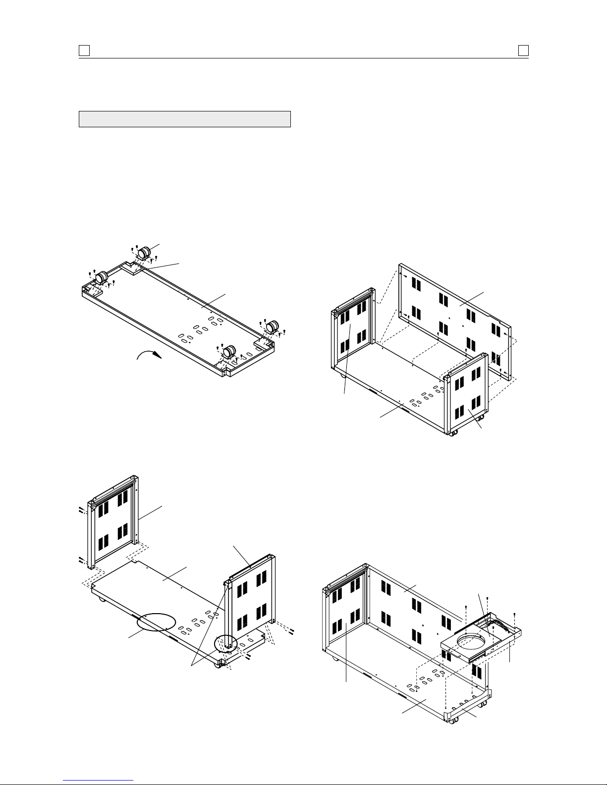
3. Install trolley side panels to the bottom panel.
Align the holes on trolley side panels with the
threaded holes at the corners of trolley bottom
panel. Tighten securely by using 8 of the
1
/4" x 50 mm
Phillips-head screws provided.
See diagram 2.
4. Install the trolley rear panel to inside of rear trolley
side panels and to rear of trolley bottom panel.
Align the holes on the trolley rear panel with the
threaded holes on trolley side panels and trolley
bottom shelf. Tighten securely by using 8 of the
1
/4" x 1/2" Phillips-head screws provided.
See diagram 3.
5. Place the cylinder pull-out tray kit on the trolley
bottom panel. Extend the cylinder tray outward
from its bracket so you can align the holes on the
bracket with the threaded holes on the top of trolley
bottom panel.
Tighten securely by using 4 of the
1
/4" x 1/2"
Phillips-head screws provided.
See diagram 4.
Slide tray back into bracket after securing to bottom.
2. Before attaching the trolley bottom panel to trolley
side panels be sure door stop for magnets on the
bottom panel and holes for door axle brackets on
trolley side panels are located on the front side.
See diagram 2.
Trolley
bottom panel
Castor
Castor
seat
Diagram 1.
Holes for door
axle bracket
Diagram 2.
Trolley
rear panel
Trolley
bottom panel
Trolley
bottom panel
Trolley side
panel – right
Trolley side
panel – left
Diagram 3.
Door stop
for magnets
Trolley side
panel – left
Diagram 4.
Trolley
rear panel
Trolley
bottom
panel
Cylinder
pull-out tray kit
(LP gas only)
1. Turn over the trolley bottom panel on floor. Install
the 4 castors to castor seats on the trolley bottom
panel.
Align the holes on castor with the threaded holes
on castor seat. Tighten securely by using 16 of the
1
/4" x 1/2" Phillips-head screws provided.
See diagram 1.
ASSEMBLING THE BARBECUE TROLLEY
Cylinder
pull-out
tray
bracket
Trolley side
panel – left
Trolley side
panel – right
Trolley side
panel – right
Page 9

ASSEMBLY
9
9
6. Before installing the door bracket to the inside of
front trolley side panels, check and ensure door
stops for magnets on the door bracket are located
on the front side.
See diagram 5.
7. Install the door bracket to the inside of front trolley
side panels. Align the threaded holes on the door
bracket with the holes on trolley side panels.
Tighten securely by using 4 of the
1
/4" x 50 mm
Phillips-head screws provided.
See diagram 5.
8. Remove the white protective film from the stainless
steel decorative panel.
9. Install the decorative panel to the trolley. Align the
2 threaded holes on the bottom of door bracket and
the 2 threaded holes on the top of bottom shelf
with the 4 holes on the decorative inside plate.
Tighten securely by using 4 of the
1
/4" x 1/2"
Phillips-head screws provided. Then tighten 4
loose screws on the door bracket.
See diagram 6
10. Install the division panel to the trolley. Align the 2
threaded holes on the decorative inside plate and 2
holes on the trolley rear panel with the holes
on the division panel. Tighten securely by using 4
of the
1
/4" x 1/2" Phillips-head screws provided.
See diagram 7.
Trolley
rear panel
Diagram 5.
Decorative
inside plate
Division
panel
Decorative
panel
Diagram 7.
Diagram 6.
Decorative
panel
Door stop
for magnets
Door
bracket
Door
bracket
Trolley side
panel – left
Trolley side
panel – right
Trolley
bottom panel
11. Remove the white protective film from the stainless
steel door panel and stainless steel door axle
bracket.
12. Install the door axle bracket-left bottom to the left
trolley side panel. Align the threaded holes on the
door axle bracket-left bottom with the holes on the
bottom of left trolley side panel. Tighten securely
by using 2 of the
3
/16" x 9 mm Phillips-head screws
provided.
See diagram 8A.
Diagram 8A.
Door axle bracket –
left bottom
Trolley side
panel – left
Trolley
bottom panel
Decorative
inside plate
Page 10

ASSEMBLY
10
10
16. Follow the steps 1 to 5 of the installing the left
cabinet door to install the right cabinet door.
17. Attach the wire basket to the left trim plate
as
shown in diagram 8D.
Tighten securely using 2 of
the
1
/4" x 1/2" Phillips-head screws provided. Place
the division wire on the wire bracket.
14. Before installing the door axle bracket-left top to
the left trolley side panel, with an assistant,
hold the door panel and keep it vertical.
15. Place the axle on top of the left door panel to the
door axle bracket-left top. Install the door axle
bracket-left top to the left trolley side panel. Align
the holes on the door axle bracket-left top with
threaded holes on the top of left trolley side panel.
Tighten securely by using 2 of the
3
/16" x 9 mm
Phillips-head screws provided.
See diagram 8C.
13. Place the axle on bottom of the left door panel to
the door axle bracket-left bottom.
See diagram 8B.
Diagram 8B.
Diagram 8D.
Hole for
door axle
Door axle bracket –
left bottom
Wire basket
hood
Door trim
plate – left
Diagram 8C.
Door axle –
left top
Hole for
door axle
Door axle bracket –
left top
Trolley side
panel – left
Trolley side
panel – left
Division
wire
Diagram 9.
Trolley side
panel
bracket
Barbecue
hood
Barbecue
body side
panel
1. Now that you have assembled the barbecue trolley
you can install the pre-assembled barbecue body.
See diagram 9. If you haven't already done so, open
the barbecue hood and remove the packed
components. Lock the castors. Even with the
components removed, the next step requires 2
people.
2. With an assistant, carefully lift and position the
barbecue body onto the barbecue trolley. Align the
6 holes of the body side panel to the threaded holes
on the trolley side panel mounting bracket. Secure
firmly by using 6 of the
1
/4" x 30 mm Phillips-head
screws provided.
INSTALLING THE BARBECUE BODY
BE CAREFUL NOT TO PINCH FINGERS
WHEN LOWERING HEAD ONTO TROLLEY
!
Page 11

1. Unscrew the igniter cap located on the control
panel and remove the contact and spring from the
igniter slot.
2. Place the supplied AA battery into the igniter slot
with the positive pole facing toward you.
3. Place the spring with contact over the battery.
screw the igniter cap back onto the control panel.
IGNITION BATTERY INSTALLATION
AA battery
Spring
Contact
Diagram 13.
1. Remove the white protective film from the stainless
steel side shelf.
2. With the aid of an assistant, attach side shelf to left
side of barbecue. Install nylon spacers onto the
1
/4" x 11/2" Phillips-head screws and then align the
holes on side shelf with the threaded holes on left
outside body panel. Tighten securely using 4 of the
1
/4" x 11/2" Phillips-head screws with spacers in
place.
See diagram 12.
3. Attach trolley side handle to right side of barbecue.
Align the holes on trolley side handle with the
threaded holes on right outside body panel.
Tighten securely using 4 of the
1
/4" x 3/4" flat-head
screws provided.
See diagram 12.
INSTALLING SIDE SHELF
AND TROLLEY SIDE HANDLE
Side shelf – left
Nylon
spacer
Diagram 12.
External body
trim panel –
right
Barbecue hood
BARBECUES ON TROLLEYS ARE HEAVY:
TO AVOID POSSIBLE INJURY CAUSED
WHEN MOVING THE BARBECUE AND
TROLLEY, THE BARBECUE SHOULD
BE PUSHED FORWARD, AND NOT
PULLED FROM BEHIND.
!
1. Attach the manual lighting stick to the external
body trim panel –left
as shown in diagram 11. Align
the hole at the end of manual lighting stick wire
with the threaded hole on the external body trim
panel. Tighten securely using the M4 x 8 mm
Phillips-head screw.
INSTALLING MANUAL LIGHTING STICK
Outside
barbecue body
panel – left
Diagram 11.
M4 x 8 mm
Phillipshead screw
Manual
lighting stick
ASSEMBLY
11
11
Diagram 10 (LP gas model only).
Control panel
Slot for wire
plug ‘A’
Fuel gauge
display
(LP gas
model only)
3. Open the front doors of cabinet. Remove fastening
band from fuel gauge display wire plug
‘A’ that is
behind the heat shield of the control panel.
4. Place the wire plug
‘A’ through the slot in side of
right trolley side panel
as shown in diagram 10.
Igniter cap
Page 12

KECHCE
CE
DF LU E IN
IN
F
AIC TOR
OR
ASSEMBLY
12
12
IMPORTANT: Before installing batteries be sure the gas
cylinder is not mounted in the cylinder pull-out tray.
1. Open the front doors of cabinet. Pull out the gas
cylinder storage tray. Connect the wire plug
‘A’
from fuel gauge display with the wire plug ‘B’
from rear of cylinder storage tray. Unscrew 1/4" x
1
/2" Phillips-head screw (lower) from rear panel
and fix wire plug
’A’ into wire fastener. Install wire
fastener to rear panel. Tighten securely using the
same screw.
See diagram 16A.
2. From the underside of the control panel, unscrew
the fuel gauge display cover on the fuel gauge
display box.
See diagram 16B.
3. Carefully remove the battery box from the back of
the fuel gauge display box and insert two ‘AAA’
batteries
(provided). Be sure to follow correct
polarity when inserting batteries.
4. Return the battery box with electric wire into the
fuel gauge display box. Screw the fuel gauge
display cover onto the fuel gauge display box.
FUEL GAUGE DISPLAY INSTALLATION
NOTE: Cylinder must be positioned in tray for fuel
gauge display check
Press the ‘CHECK’ button to operate fuel gauge display.
1.
Fuel display: Indicates gas cylinder fill level
2.
Fuel Warning display: When the gas cylinder fill
level is on the last row a warning signal will
sound for approximately 3 seconds to warn you
that the cylinder volume is near empty.
3.
Battery Warning display: A low battery warning
light will illuminate when the battery voltage
drops to a low level. Replace the batteries.
IMPORTANT: When the gas cylinder is removed from
the cylinder storage tray, the fuel gauge display will
not operate.
FUEL GAUGE DISPLAY OPERATING
Diagram 16A.
Diagram 16B.
Trolley side panel – right
Wire plug ‘A’
Wire plug ‘A’
Wire plug ‘B’
AAA battery
Wire plug ‘A’
Fuel gauge
display
Fuel gauge
display cover
Check button
Fuel warning
display
Battery
warning
display
Fuel level
display
Fuel gauge
display box
Cylinder
pull-out tray
Wire fastener
Rear panel
Install the 5/16" x 89 mm wing bolt as shown below
to secure the gas cylinder in place during use.
GAS CYLINDER LOCK
Wire
Battery box
Cylinder
pull-out tray
5/16"x 89 mm wing bolt
Page 13

GAS INSTALLATION
13
13
1. Attach hose and regulator assembly to the main
barbecue gas piping. Tighten securely with a
shifter.
2. Locate the gas cylinder onto the gas cylinder storage
tray on the RHS of the trolley bottom panel.
Refer diagram below.
3. Attach the cylinder connection device of regulator
and hose assembly to cylinder valve outlet.
4. Open the gas cylinder valve fully to allow gas to
flow.
5. Leak test all accessible connections thoroughly
with a soapy water solution prior to lighting the
barbecue.
Refer to Safety information at beginning of booklet.
6. If a leak is found, turn gas cylinder valve off and do
not use barbecue until repairs or replacement can
be made by a local gas supplier.
DISCONNECTING FROM GAS SOURCE
1. Turn the burner control ‘OFF’.
2. Turn the gas cylinder valve off fully.
3. Detach the regulator assembly from gas cylinder
valve.
CONNECTING AND DISCONNECTING
TO GAS SOURCE
TEST FOR LEAKS WITH A
SOAP SOLUTION, NEVER WITH AN
OPEN FLAME. (Refer page 4)
!
Gas
cylinder
CONNECTING TO GAS SOURCE
IF THIS INFORMATION IS NOT
FOLLOWED EXACTLY, A FIRE
CAUSING DEATH OR SERIOUS INJURY
MAY OCCUR!
DO NOT STORE A SPARE GAS CYLINDER
IN THE STORAGE COMPARTMENT OR
NEAR THIS APPLIANCE.
NEVER FILL THE CYLINDER BEYOND
80% FULL.
THIS BARBECUE IS ONLY TO BE USED
OUTDOORS.
!
DISCONNECT OR REMOVE GAS
CYLINDER WHEN MANOEUVRING THE
BARBECUE OVER UNEVEN SURFACES
OR CARRYING UP AND DOWN STAIRS
!
IMPORTANT: Before connecting and disconnecting
barbecue to gas source, make sure all burner controls
are in ‘OFF’ position.
NOTE:
The ‘OFF’ position on the control panel is
identified by a black vertical line. When the line or the
word ’OFF’ printed on the control knob aligns with the
black vertical line on the control panel, the burner is in
the fully ‘OFF’ position.
CAUTION:
When the appliance is not in use, the gas
must be turned off at the gas cylinder.
Familiarise yourself with the general information
and safety guidelines located at the front of this
manual. Check to see that gas cylinder is filled and that
the end of each burner tube is properly located over
each valve orifice. Set burner controls to
‘OFF’ position.
ENSURING BURNER CONTROLS ARE OFF
This barbecue is also certified for use on natural gas.
Contact the distributor for advice in relation to using
your barbecue on natural gas.
Refer back cover.
If your barbecue is supplied direct from the factory
in a natural gas specification, then it must be installed
by an authorised person.
SETTING OF THE ‘APPLIANCE TEST POINT
PRESSURE’ ON NATURAL GAS
Operate 4 right burners on ‘HI’. Attach manometer to an
injector of one of the unlit burners. Adjust regulator
until 1 kPa pressure is achieved with 4 burners operating.
NATURAL GAS INSTALLATION
Page 14

INSPECTION
14
14
Product shipping can reposition the back burner spark
electrode. If your barbecue and side burner are
completely assembled and this rotisserie burner electrode
does not continuously
spark, then conduct
this adjustment.
1. Turn the gas supply off at the gas cylinder.
2. Be sure the AA battery is installed and follow all
ignition wires to ensure the connections are secure.
3. Push the ignition button and watch for a small blue
spark at the rotisserie burner electrode tip. If there is
no spark you must adjust the gap between the
electrode tip and the stainless steel rotisserie burner
screen. The gap should be adjusted to 5 mm or closer.
ROTISSERIE BURNER
SPARK ELECTRODE TEST AND ADJUSTMENT
Do not touch the
white ceramic
electrode insulator
CHECK PERFORMANCE OF
BURNERS PRIOR TO INSTALLING
BARBECUE PLATE COMPONENTRY.
DO NOT SMOKE WHEN ATTEMPTING TO
IGNITE BARBECUE.
NEVER USE VOLCANIC ROCK,
HEAT BEADS OR OTHER MATERIAL
ON FLAMETAMER.
ALWAYS USE PROTECTIVE
GLOVES WHEN HANDLING HOT
COMPONENTS.
!
1. With burner controls in ‘OFF’ position, open the gas
cylinder valve or connect to gas supply.
2. Upon first assembly the gas lines and burners will be
full of air. In order for the burners to light properly
the lines must fill with gas. It may require several
attempts at lighting the burners before you are
successful.
3. Push the igniter button and check for sparking at the
stainless steel gas collector, located adjacent to each
burner.
4. If a spark is not evident at the gas collector, check that
the ignition lead is firmly attached to the spark plug.
5. With sparking established at collector box, turn the
burner control to
‘HI’ to establish a flame on the burner.
6. Push and turn the required burner control as required
in an anti-clockwise direction to the
‘HI’ position.
Cross lighting channels inside the barbecue body
enables the flame to transfer across to the centre and
opposite side burners to ignite them.
7. If any burners fail to light after several attempts, turn
off gas supply at source.
Wait until burners cool and inspect for obstructions to gas
flow.
See also Safety instructions (page 4), Lighting and
Operating instructions (page 16)
.
BURNER OPERATION
AND IGNITION SYSTEM CHECK
Burner tubeOrifice
Gas
valve
Gas collector box Screw
Continuous igniter
Spark electrode Burner port
Foot
Cotter pin
Burner control
Burner
5 mm
Before placing the cooking components into your
barbecue body, ensure that the spark electrode tip is
properly positioned within each gas collector box
(a wide
stainless steel mechanism found at the front between each set
of burners)
. The easiest way to ensure this is to perform the
following electrode check:
1. Be sure all control knobs are set to
‘OFF’. Open the
barbecue hood. NEVER put your face inside the
barbecue body.
2. Press igniter cap and look down at the gas collector
box. If a spark is present the electrode tips are properly
positioned.
3. If no spark is seen, then the spark gap shown below
needs to be adjusted as follows:
• Using an adjustable wrench, loosen the inside nut just
until the gas collector box can be manoeuvred and
turned upward.
The gap between the spark electrode tip and spark
receiver should be approximately 5 mm.
• If the gap is wider the 5 mm use a pair of long nose
pliers and gently squeeze the gas collector box until
the gap is correct.
• Return the gas collector box to its original horizontal
position, secure the inside nut and try the electrode
check again.
MAIN BURNER ELECTRODE CHECK
Gas collector box
Inside nut
5 mm spark gap Spark electrode tip
4. Adjust the gap using needle nose pliers. DO NOT
adjust the gap by hand or touch the white ceramic
electrode insulator. Using one set of needle nose pliers,
securely hold the electrode as shown above. With
another set of pliers, gently bend the tip end of
electrode to within 5 mm of the stainless steel screen.
Be careful not to puncture the screen or break electrode
tip.
5. Try spark electrode test again. Re-adjust if necessary.
Page 15

Check and ensure that each burner is properly located
over each orifice prior to installing the flametamer.
1. The flametamer is designed to reduce flaring.
Place the flametamers on the lower edge above
burners. Flametamers must always be located under
the grillplate.
2. Position the cooking plates as shown below.
3. Place the secondary cooking rack into the slots
on the barbecue body rails.
INSTALLING COOKING COMPONENTS
Place heat shield into pull-out grease draining tray. The
heat shield must be present and centred for your safety.
Slide the pull-out grease draining tray into the tracks on
the trolley side panels and push until it stops.
See diagram 18.
With the grease tray fully pushed in, install the 2 x M5
winged screws into the weld nuts located on the
underside of the grease tray rails. These can be accessed
from the inside of the cabinet and are approximately
85 mm from the front.
NOTE: The grease tray must be properly installed and
fully pushed in when the barbecue is operating.
INSTALLING PULL-OUT GREASE TRAY
Cooking
grid
Secondary
cooking rack
Slots for rack
Flametamer
Pot support
Hotplate
Side burner
Diagram 14.
INSPECTION
15
15
CONTENTS OF FAT/GREASE
DRAINING TRAY AND FAT/GREASE
RECEPTACLE MAY BE VERY HOT
DURING COOKING.
ALLOW TO COOL COMPLETELY
BEFORE DISPOSING OF THE
CONTENTS.
LINING THE FAT/GREASE
RECEPTACLE WITH ALUMINIUM FOIL
ENABLES EASIER CLEANING.
REMEMBER:
REPLACE FAT/GREASE
DRAINING TRAY FOIL REGULARLY.
AFTER CONTINUOUS USE, FAT AND/
OR COOKING JUICES MAY BUILD UP.
TO AVOID ANY FLARE-UPS, IT IS
RECOMMENDED THAT THE
FAT/GREASE TRAY AND RECEPTACLE
BE EMPTIED REGULARLY.
!
DO NOT GRIP THE LEFT SIDE SHELF
TO ALTER ITS POSITION; ALWAYS
GRIP THE STAINLESS STEEL HANDLE
ON THE RIGHT SIDE OF BARBECUE
TO CHANGE ITS POSITION.
!
Page 16

The fats and juices that drip from the meat may cause
flare-ups. Since flare-ups impart the distinctive taste
and colour for food cooked over an open flame, they
should be expected and encouraged within reason.
Nevertheless, uncontrolled flaring can result in a ruined
meal.
FLARE-UPS
OPERATION
16
16
Before first use and at the beginning of each barbecue
season:
1. Please read
Safety, Lighting and Operating
Instructions
carefully.
2. Check gas valve orifices, burner tubes and burner
ports for any obstructions
eg. spiders, webs, insects.
3. Check and ensure the gas cylinder is full.
4. Ensure all connections are securely tightened.
Check for gas leaks.
See page 3.
NOW YOUR BARBECUE IS READY TO USE
1. Open barbecue hood before attempting to light
burners.
2. Set control knobs to
‘OFF’
and open the gas cylinder
valve.
3. Push and turn the required
control knob to
‘HI’.
4. Immediately press the
continuous spark igniter
for 3 - 4 seconds to light the
burner.
5. If the burner does not light,
turn the control knob to
‘OFF’, wait 5 minutes for
gas to clear, then retry.
6. Once the burner is ignited,
the adjacent burner can be
lit by simply turning its control knob to ‘
HI’.
7. Adjust control knobs to your desired cooking
temperature.
8. If ignition cannot be achieved, perform ignition
check procedure.
Refer page 14.
MAIN BURNER IGNITION
THE HOOD MUST BE IN THE OPEN
POSITION, FOR LIGHTING
DO NOT SMOKE AT ALL TIMES WHEN
ATTEMPTING TO IGNITE BARBECUE.
CAUTION:
DO NOT MOVE TROLLEY
WHILE BARBECUE IS IN OPERATION
!
CAUTION: DO NOT LEAVE THE
BARBECUE UNATTENDED WHEN
BURNER/S IS ALIGHT.
!
ANY OF THE FOLLOWING SIGNS MAY
INDICATE THAT THE APPLIANCE IS
NOT OPERATING PROPERLY AND MAY
NEED SERVICING:
• EXCESSIVE YELLOW FLAME
• IRREGULAR SIZE OF FLAME
ACROSS BURNER
•‘POPPING’ OF FLAME
• SOOTING
• ABNORMAL NOISE(S)
• HISSING SOUND
NOTE:
Before requesting service,
please refer to page 19 ‘If Barbecue Fails to
Operate Properly’
!
If for some reason, igniters fail to produce a spark at the
electrode, barbecue can be lit carefully with a match.
To light barbecue with a match, refer previous
steps. Insert match into lighting stick provided and
insert lit match through lighting hole located on left side
of barbecue body, after turning the left burner control
to the
‘HI’ position.
Sequentially light the remaining burners from left
to right.
MANUAL IGNITION
NEVER LEAN OVER THE BARBECUE
COOKING AREA WHILE LIGHTING THE
APPLIANCE.
KEEP YOUR FACE AND BODY AT A SAFE
DISTANCE (AT LEAST 450 mm) FROM THE
MANUAL LIGHTING HOLE OR BURNERS.
!
Page 17

NOTE: The location of the rotisserie burner makes it
more susceptible to wind conditions that will decrease
the performance of your rotisserie cooking. For this
reason you should not operate the rotisserie burner
during windy weather conditions.
1. Open barbecue hood before attempting to light
rotisserie burner.
2. Set control knobs to
‘OFF’ and open the gas cylinder
valve.
3. Push and turn rotisserie burner control knob to ‘
HI’.
4. Then immediately press the continuous spark
igniter for 3 - 4 seconds to light the burner.
5. If the burner does not light, turn the control knob
to ‘
OFF’, wait 5 minutes, then retry.
6. Once the burner is ignited, the rotisserie burner
will reach cooking temperature quickly. The
orange/red glow will even out in about 5 minutes.
7. For best results, always rotisserie cook with the
hood down.
NOTE: If extra heat is required, then any of the main
burners may be used on the ‘LOW’ setting only.
ROTISSERIE BURNER IGNITION
OPERATION
17
17
CAUTION: IF BURNERS GO OUT
DURING OPERATION, CLOSE GAS
SUPPLY AT SOURCE, AND TURN ALL
BURNER CONTROLS OFF.
OPEN HOOD AND WAIT 5 MINUTES
BEFORE RE-ATTEMPTING TO LIGHT
(ENSURE ACCUMULATED GAS FUMES
HAVE CLEARED).
CAUTION:
SHOULD A GREASE FIRE
OCCUR, ATTEMPT TO CLOSE GAS
SUPPLY AT SOURCE, TURN OFF ALL
BURNERS AND REMOVE FOOD
IF POSSIBLE.
KEEP THE VENTILATION OPENINGS OF
THE CYLINDER ENCLOSURE FREE AND
CLEAR FROM DEBRIS.
!
THE SIDE BURNER IS DESIGNED FOR USE
WITH A WOK UP TO 360 mm DIAMETER,
AND COOKING PAN OF UP TO 200 mm
DIAMETER.
USE OF VERY LARGE POTS MAY RESULT
IN DISCOLOURATION OF THE SURFACE
FINISH, OR CAUSE POOR COMBUSTION.
!
1. Open side burner lid before attempting to light
side burner.
2. Set control knobs to
‘OFF’ and open the gas cylinder
valve.
3. Push and turn the control knob for side burner to
‘HI’.
4. Immediately press the continuous spark igniter for
3 - 4 seconds to light the burner.
5. If the burner does not light, turn the control knob
to
‘OFF’, wait 5 minutes, then retry.
6. Adjust control knob to your desired flame level.
SIDE BURNER IGNITION
BURN-OFF
Before cooking on your barbecue for the first time,
burn-off any residual oils or foreign matter from the
cooking plates.
ENSURE THE HOOD IS OPEN, and
operate at
‘HI’ setting for approximately 15 minutes.
Allow to cool then wash grillplates/hotplate thoroughly
with soap suds and scrubbing brush. Rinse thoroughly
and wipe clean with a cloth.
PREHEATING
It is necessary to preheat the barbecue before
cooking. Operate the burners under the cooking surface
to be used at
‘HI’ for approximately 10 minutes before
cooking. Hooded barbecues should be pre-heated with
the hood down.
OPERATING PROCEDURE
‘HI’ setting – Use this setting only for warm up, for
searing steaks and chops, and for burning food residue
from the plates after the cooking is over. Rarely, if ever,
do you use the ‘
HI’ setting for extended cooking.
‘MED’ setting (mid-way between ‘HI’ and ‘LOW’).
Use this setting for most grilling, and for cooking
hamburgers and vegetables.
‘LOW’ setting – Use this setting when cooking very
lean cuts such as fish.
Actual cooking surface temperatures vary with
outside temperature and the wind conditions.
COOKING TEMPERATURES
Page 18

OPERATION
18
18
Cooking with the hood in the closed position helps to
cook food more quickly than in conventional open-style
barbecues with a lid. The hood
(when closed) helps to
retain the heat more evenly and conserves energy. For
the best cooking results, always use the burners on
‘MED’ or ‘LOW’ and use the indirect cooking method
(explained below) when the hood is down. High direct
heat on the cooking plates when the hood is down may
result in burnt food, or damage to your barbecue.
The following methods are referred to as
‘INDIRECT
COOKING’
. Poultry and large cuts of meat cook slowly
to perfection on the barbecue by indirect heat.
The heat from the selected burners circulates gently
throughout the barbecue, cooking the meat or poultry
without any direct flame touching it. This method
greatly reduces flare-ups when cooking extra fatty cuts,
because there is no direct flame to ignite the fats and
juices that drip during cooking.
REMEMBER: Only use burners on ‘LOW’ for indirect
cooking. Only use outside burners for indirect cooking.
Remove solid hotplate from barbecue body and
position grillplate and flametamers over centre burners.
With the hood open, ignite the outer left and right
burners. Once ignition is established, close the hood.
Leave the burners on ‘
HI’ for 10 minutes or until the
temperature reaches a suitable level for cooking.
Modulate the required temperature by turning the
outermost burners progressively to
‘MED’ or ‘LOW’.
Do not ignite the burners directly under the meat.
Food should be positioned in the centre position either
in a shallow ovenproof dish or a disposable aluminium
foil to retain juices for basting.
Extremely large cuts of food, such as turkey may be
placed in the baking dish directly over the flametamer .
BARBECUING WITH THE HOOD DOWN
NEVER USE ANY BURNER, OR
COMBINATION OF BURNERS ON ‘HI’
WHEN COOKING WITH THE HOOD
DOWN.
!
ROTISSERIE COOKING
Rotisserie cooking produces foods that are moist,
flavourful and attractive. The rotisserie system is most
commonly used for cooking meat or poultry and is
designed to cook food from the rotisserie burner using
infrared heat. The rotisserie burner is an infrared type,
which provides intense searing radiant heat. The
intense heat sears in the natural juices and nutrients
found in quality cuts of meat.
The cooking times on a rotisserie will vary
accordingly depending on the size and the cut of the meat.
BALANCING THE FOOD
In rotisserie cooking, balancing the food is of utmost
importance. The rotisserie must turn evenly or the
stopping and starting action will cause the food to cook
unevenly and possibly burn the heavier side.
The easiest foods to balance are those of uniform
shape and texture. To test if the food is balanced
correctly when secured, place the ends of the rotisserie
spit loosely in the palms of your hands. If there is no
tendency to roll, give the spit a quarter turn. If it is still
stable, give it a final quarter turn. It should rest without
turning in each of these positions.
To load the spit rods, begin with handle in place on
slot located in barbecue side panel. Slide one of the
holding forks
(with prongs facing away from the handle)
onto the spit rod. Push the spit rod through the centre
of the food to be basted, and then slide the second
holding fork,
(prongs toward the food) onto the spit rod.
It is very important to centre and balance the food to be
cooked on the spit rod, then push the meat holding
forks firmly together. Tighten the wing nuts with pliers.
It may also be necessary to wrap the food with butcher
string
(never use plastic or nylon string) to secure any
loose portions.
A rolled piece of meat requires the rotisserie skewer
to be inserted through the centre of the length of meat,
then secured and balanced.
For meats that contain bones, it is best to secure the
rotisserie skewer diagonally through the meaty sections.
If protruding bones or wings brown too quickly, cover
with pieces of foil.
GUIDE TO ROTISSERIE COOKING
WITH THE ROTISSERIE BURNER
Page 19

FAULT FINDING
19
19
1. Turn off gas at source, turn burner control to ‘OFF’.
2. Wait five minutes before trying again.
3. Check gas supply/connections.
4. Repeat lighting procedure and, if barbecue still
fails to operate properly,
TURN OFF GAS AT
SOURCE, TURN BURNER CONTROLS TO ‘OFF’,
wait for barbecue to cool and check the following:
a) Misalignment of burner tube(s) and over orifice(s).
CORRECTION: Reposition burner tube to properly
sit over orifice.
b) Obstruction in gas line
CORRECTION: Remove hose from barbecue.
DO NOT SMOKE! Open gas supply for one second
to blow any obstruction from fuel hose. Close off
gas supply at source and reconnect hose to barbecue.
c) Blocked orifice
CORRECTION: Remove grillplates, flametamers,
fat/grease draining tray. Remove burners from
bottom of barbecue body by pulling cotter pin from
beneath burner ‘foot’ using a screwdriver or needle
nose pliers.
See burner diagram on page 14. Carefully
lift each burner up and way from gas valve orifice.
Remove the orifice section of gas valve from each
gas valve and gently clear any obstruction with a
fine wire. Re-install each orifice section, re-install
burners over orifices and place each burner ‘foot’
into mounting bracket at bottom of barbecue body.
Replace cotter pins. Replace cooking components,
fat/grease draining tray.
d) Misalignment of igniter on burner
CORRECTION: Check for proper position of
electrode tip. The tip of the electrode should be
pointing toward the tip of the collector box. The
gap between the spark electrode and the tip of the
gas collector box should be 5 mm. Adjust if
necessary by carefully pressing the gas collector
closer to the spark electrode.
If re-ignition is necessary while the barbecue is still
hot, you must wait for a minimum of five minutes
before commencing to re-ignite.
(This allows accumulated
gas to clear).
If all check/corrections have been made and
barbecue still fails to operate properly, consult your
place of purchase, or contact the manufacturer.
IF BARBECUE FAILS TO OPERATE PROPERLY
BEWARE OF SPIDERS.
BURNER TUBES SHOULD BE
INSPECTED AND CLEANED
PERIODICALLY.
SPIDERS AND SMALL INSECTS CAN
OCCASIONALLY SPIN WEBS OR MAKE
NESTS IN THE BURNER TUBES.
THESE WEBS CAN LEAD TO A GAS
FLOW OBSTRUCTION WHICH COULD
RESULT IN A FIRE IN AND AROUND
THE BURNER TUBES.
THIS TYPE OF FIRE IS KNOWN AS
‘FLASH-BACK’ AND CAN CAUSE
SERIOUS DAMAGE TO YOUR
BARBECUE AND CREATE AN UNSAFE
OPERATING CONDITION FOR THE USER.
ALTHOUGH AN OBSTRUCTED BURNER
TUBE IS NOT THE ONLY CAUSE OF
‘FLASH-BACK’ IT IS THE MOST
COMMON CAUSE AND FREQUENT
INSPECTION AND CLEANING OF THE
BURNER TUBES IS NECESSARY TO
PREVENT ITS OCCURRENCE.
!
SAFETY POINTS
• Do not operate damaged rotisserie.
• Do not use rotisserie in poor weather conditions.
• Avoid contact with hot surfaces.
• Always load rotisserie to barbecue before switching
motor on.
• Always turn rotisserie
‘OFF’ before removing from
barbecue.
• Do not leave rotisserie on barbecue when not in use.
LOADING THE SPIT RODS
• Assemble rotisserie rod as shown.
• Centre food on the spit rod.
• Use butcher string to secure loose portions.
Rotisserie is available as an optional extra from your place of
purchase.
ROTISSERIE
Occasionally check burner
flame for correct operation
as shown
. Either view
flame through manual
lighting opening on left
side of barbecue body
panel or remove cooking
plates
.
VISUALLY CHECKING BURNER FLAMES
Page 20

MAINTENANCE
20
20
To reduce the chance of flash-back, the procedure below
should be followed at least once a month in late summer
or early autumn when spiders are most active, or when
your barbecue has not been used for an extended period
of time.
1.
Remove grillplates, flametamers, fat/grease draining
tray from barbecue body.
2. Remove burners from bottom of barbecue body by
unscrewing the burner securing screw at the burner
‘foot’ using a screwdriver.
3. Carefully lift each burner up and away from gas
valve orifice.
We suggest several different ways of cleaning the
burner tubes. Use the procedure most convenient for
you:
Bend a stiff wire
(a light weight coat hanger works
well)
into a small hook. Run the hook through each
burner tube and into the burner several times.
CLEANING THE BURNER TUBES AND
BURNER PORTS (TO PREVENT FLASH-BACK)
OR Using a narrow bottle brush with a flexible handle
(do not use a brass wire brush), run the brush through
each burner tube and into the burner several times.
OR Use an air hose to force air through the burner tube
and out through the burner ports. Observe each
port and make sure air comes out every hole. Wear
eye protection.
NOTE: Do not use compressed air with injectors.
Regardless of which burner cleaning procedure
you use, we recommend that you complete the following
steps to help prolong burner life.
1. Wire brush entire outer surface of burner to
remove food residue and dirt.
2. Clean any blocked ports with a stiff wire such as an
open paper clip.
3. Inspect the burner for damage
(cracks or holes) and
if such damage is found, order and install a new
burner. After installation, check to ensure that gas
valve orifices are correctly placed inside ends of
burner tubes. Also check position of spark electrode.
If fire occurs in and around the burner tubes, immediately
turn off gas at its source and turn the burner control(s)
to
‘OFF’. Wait until the barbecue has cooled, then clean
the burner tubes and burner ports as described,
opposite.
FLASH-BACK
As with all appliances, proper care and maintenance will
keep them in top operating condition and prolong their
life. Your new gas barbecue is no exception. By
following these cleaning procedures on a timely basis,
your barbecue will be kept clean and working properly
with minimum effort.
CARE AND MAINTENANCE
After cooking, turn burner controls to ‘OFF’ and let
barbecue cool before attempting to clean your cooking
plates.
Before first use and periodically it is suggested that
you wash the cooking plates in a mild soap and warm
water solution. You can use a wash cloth, a vegetable
brush, or steel wool to clean your barbecue plates if you
desire.
CLEANING THE COOKING PLATES
Washing the flametamer after every use is not necessary
but periodically it is suggested you clean off any
build-up of food residue. Use a wire brush to remove
stubborn burnt on cooking residue.
Dry the flametamer thoroughly before re-installing it
into the barbecue body.
NOTE: Flametamers are coated with a ceramic material
which can be easily damaged if not handled with care.
CLEANING THE FLAMETAMER
The fat/grease draining tray should be emptied and
wiped down periodically and washed in a mild detergent
and warm water solution. Lining the tray with aluminium
foil will enable easier cleaning.
CLEANING THE FAT/GREASE DRAINING TRAY
Follow the instructions provided on page 11.
IGNITION BATTERY REPLACEMENT
Page 21

MAINTENANCE
21
21
INTERIOR:
1. Turn the burner controls to ‘OFF’ position.
2. Turn the cylinder valve off fully.
3. Detach the regulator assembly from cylinder valve.
4. Remove and clean the cooking plates, flametamers
and burners.
5.
Cover the gas valve orifices with a piece of aluminium
foil.
6. Brush the inside and bottom of the barbecue with a
stiff wire brush, and wash down with a mild soap
and warm water solution. Rinse thoroughly and
let dry.
7. Remove aluminium foil from orifices and check
orifices for any obstruction.
8. Check spark electrode, adjusting as instructed.
Electrode tip pointing toward the bottom of gas
collector and approximately 5 mm from the bottom
of collector box.
9. Replace burners and adjust spark electrode collector
box.
10. Replace flametamer, plates and warming rack.
11. Reconnect to gas and observe burner flame for
correct operation.
As with all appliances, proper care and maintenance
will keep them in a top operating condition and prolong
their life. Your barbecue is no exception. By following
these cleaning procedures on a timely basis, your
barbecue will be kept clean and working properly with
minimum effort.
EXTERIOR:
Your gas barbecue is made of durable grade stainless
steel, it should provide you with years of trouble-free
service.
Refer to care of stainless steel, opposite.
DO NOT USE OVEN CLEANER
TO CLEAN THE BARBECUE.
!
Burning-off the barbecue after cooking will keep it
ready for instant use, however, once a year you should
give the entire barbecue a thorough cleaning to keep it
in top operating condition.
ANNUAL CLEANING OF BARBECUE BODY
The stainless steel over time will be affected by ‘tea
staining’
(the brown discolouration of some stainless steel).
Tea staining can be reduced by washing the surface
with mild detergent and warm water. This should then
be followed by rinsing with clean cold water. We
recommend the surface then be wiped dry with a clean
cloth.
CARE FOR STAINLESS STEEL SURFACE
We recommend that you minimise the unit’s exposure
to the elements. High moisture content in the air
(rain,
mist, salt spray etc.)
can affect metal components of this
appliance and lead to material breakdown. If left in an
area subjected to high moisture content, we strongly
recommend that you observe the cleaning procedure on
a regular basis and cover the appliance whilst not in use
(covers are available as an optional extra if not supplied with
the appliance)
. Material breakdown from high moisture
conditions can be avoided if the appliance is well
protected from the weather and regular cleaning is
carried out.
STORAGE
IN COASTAL AREAS, FREQUENT
CLEANING AND THE USE OF A COVER
IS RECOMMENDED TO PROLONG THE
LIFE OF THE APPLIANCE.
SALTY AIR WILL ADVERSELY AFFECT
EXPOSED PARTS.
!
Page 22

OUTDOOR AREAS
22
22
The following diagrams are examples of outdoor areas. The same principles apply to shaded areas.
Page 23

RINNAI NEW ZEALAND. LTD
Head Office: 691 Mt. Albert Rd, Royal Oak, Auckland.
PO Box 24-068.
Tel (09) 625 4285. Fax (09) 624 3018.
Internet: www.rinnai.co.nz
Email: sales@rinnai.co.nz
For your local
Service Centre
contact: 0800 RINNAI (0800 746624).
Customers in Australia, refer to back cover.
23
23
✁
YOUR DETAILS
Mr Mrs Ms Other:
Surname: Given name:
Address:
Suburb/Town: P/code:
Telephone ( ) A/H, Bus:
YOUR BARBECUE DETAILS
Date of purchase:
Place of purchase:
Serial No. located on front/side panel:
ADDITIONAL DETAILS
(Optional questions to assist our continuous improvement program)
Before this purchase, were you aware of Rinnai? Yes No
If yes, were you aware that Rinnai produced
an extensive barbecue range? Yes No
What was your final choice based on?
Colour Price Features Style Other:
Were you recommended to this product by
Retailer Friend Advertising Past Experience Other:
Did you previously own a barbecue? Yes No
If yes, what kind? Portable Kettle Inbuilt
Volcanic Rock/Charcoal Same Other:
If you changed, why?
Your age 20-25 26-30 31-35 36-40 41-45 46-50 50+
✁
YOUR DETAILS
Mr Mrs Ms Other:
Surname:
Given name:
Address:
Suburb/Town:
State: P/code:
Telephone ( )
A/H, Bus. ( )
YOUR BARBECUE DETAILS
Date of purchase:
Place of purchase:
Serial No. located on front/side panel:
ADDITIONAL DETAILS
(Optional questions to assist our continuous improvement program)
Before this purchase, were you aware of
Rinnai Aust? Yes No
If yes, were you aware that Rinnai
produced an extensive barbecue range? Yes No
What was your final choice based on?
Colour Price Features Style Other:
Were you recommended to this product by
Retailer Friend Advertising Past Experience
Other:
Did you previously own a barbecue? Yes No
If yes, what kind? Portable Kettle Inbuilt
Volcanic Rock/Charcoal Same Other:
If you changed, why?
20-25 26-30 31-35 36-40 41-45 46-50 50+
All personal information collected through this request is primarily for
purposes of enquiry warranty information. From time to time Rinnai
may be running special product promotional or product servicing offers.
If you would like to receive any informational on these offers please tick
this box .
For more information regarding our privacy statement, please contact our
privacy officer on (03) 9721 6625 during business hours or write to
PO Box 460, Mordialloc VIC 3195.
Your
age
Page 24

PART NO. P80140004A Printed 6/2003 All specifications are subject to change without notice.
Freepost Rinnai NZ Ltd
Marketing Department
P O Box 24068
Royal Oak
Auckland
Rinnai Australia has a service network in most states.
Our service network personnel are fully trained and
equipped to give the best service on your Rinnai appliance.
If your barbecue needs service please ring one of the
contact numbers on this page.
RINNAI AUSTRALIA PTY. LTD. ABN 74 005 138 769
Rinnai
Help Line: 1 300 366 388, 8.30am - 6.00pm EST Mon - Fri
(Cost of a local call. Higher from mobile or public phones).
Internet: www.rinnai.com.au
e-mail: enquiry@rinnai.com.au
Head Office:
Sales,
Spare Parts 10-11 Walker Street, Braeside, Vic 3195.
& Service: Tel 1 300 366 388. Fax (03) 9271 6611.
N.S.W. Branch:
Sales & 62 Elizabeth St, Wetherill Park, NSW 2164.
Service: Tel (02) 9609 2888. Fax (02) 9609 5260.
S.A. Branch:
140 Days Rd, Ferryden Park, SA 5010.
Tel 1300 366 388. Fax (03) 9271 6611.
W.A. Branch:
Sales & 18 Belgravia St, Belmont, WA 6014.
Service: Tel (08) 9479 9479. Fax (08) 9277 2531.
QLD Branch:
Sales & 1/6 Booran Dve, Logan City, QLD 4114.
Service: Tel (07) 3209 4622. Fax (07) 3209 4722.
Tasmania: Contact Rinnai Melbourne on
Sales &
Service: Tel 1300 366 388. Fax (03) 9271 6611.
OUR BRANCHES
Delivery Address:
PO Box 460
MORDIALLOC VIC 3195
Rinnai Australia Pty Ltd
Reply Paid 460
MORDIALLOC VIC 3195
No stamp required
if posted in Australia
 Loading...