

Rinnai IB35RBN, IB35RBL, IB35RBUS, IB35RUS Owner's Operation And Installation Manual

IB35RBN/US
IB35RBL/US
Gas Radiant Space Heater
Owners Operation and Installation Manual
Do not store or use gasoline or other flammable vapors
and liquids in the vicinity of this or any other appliance.
WHAT TO DO IF YOU SMELL GAS
• Do not try to light any appliance.
• Do not touch any electrical switch; do not use any phone in
your building.
• Immediately call your gas supplier from a neighbor’s phone.
Follow the gas supplier’s instructions.
• If you cannot reach your gas supplier, call the fire department.
Installation and service must be performed by a qualified
installer, service agency or the gas supplier.
This heater has been designed to code ANSI Z 21.88a-2000
effective 7-1-2002
This appliance is only for use with the type of gas indicated on
the rating plate.
This appliance is not convertible for use with other gases.
INSTALLER: MUST LEAVE THIS MANUAL WITH THE UNIT AFTER INSTALLATION
OWNER: RETAIN THIS MANUAL SAFELY, FOR FUTURE REFERENCE
zx
HOME OWNER / INSTALLER
FOR YOUR SAFETY
THIS MANUAL MUST BE READ IN ITS
ENTIRETY BEFORE OPERATING HEATER
WARNING: If the information in these instructions are not
followed exactly, a fire or explosion may result causing
property damage, personal injury or loss of life.

2
LIMITED WARRANTY
RINNAI FIREPLACE HEATER
WHAT IS COVERED?
This Warranty covers any defects in materials or workmanship, subject to the terms stated below. This
Warranty extends to the original purchaser and subsequent transferees, but only while the product remains at
the site of the original installation. This Warranty only extends through the first installation of the product and
terminates if the product is moved or reinstalled at a new location.
HOW LONG DOES COVERAGE LAST?
Item Period of Coverage
All Parts and Components 2 Years from Date of Purchase
WHAT WILL RINNAI DO?
Rinnai will repair or replace the product or any part or component that is defective in materials or workmanship,
except as set forth as follows. Rinnai will pay reasonable shipping costs, provided you obtain prior authorization
from an Authorized Rinnai Distributor. Rinnai will not pay labor charges associated with the repair or replacement
of the product or any part or component. All repair parts must be genuine Rinnai parts. All repairs or replacements
must be performed by an individual or servicing company that has been authorized by Rinnai or its distributor.
Replacement of the product or replacement of the heat exchanger may be authorized by Rinnai only. Rinnai
does not authorize any person or company to assume for it any obligation or liability in connection with the
replacement of a product or heat exchanger. If Rinnai determines that repair of a product is not possible,
Rinnai will replace the product with a comparable product, at Rinnai’s discretion.
HOW DO I GET SERVICE?
You must contact an Authorized Distributor or Installer for the repair of a defective product under this Warranty.
Failure to contact an Authorized Distributor or Installer will void the Warranty. For the name of the Authorized
Distributor or Installer nearest you, please contact your local HVAC dealer or gas service technician, visit the
Rinnai website (www.rinnai.us), call Rinnai at 1-800-621-9419 or write to Rinnai, 103 International Drive, Peachtree
City, Georgia 30269.
Proof of purchase is required. You can show proof of purchase with a dated sales receipt, or by completing
and mailing the enclosed Warranty registration card within 30 days of purchasing the product. Please complete
the enclosed Warranty registration card and mail it to Rinnai at the address shown on the card. Receipt of this
card by Rinnai will constitute proof-of-purchase for this product. However, return of this Warranty registration
card is not necessary in order to validate this Warranty.
WHAT IS NOT COVERED?
This Warranty does not cover any failures or operating difficulties due to accident, abuse, misuse, alteration,
misapplication, force majeure, improper installation, improper maintenance or service, or for any other causes
other than defects in materials or workmanship. This warranty does not apply to any product whose serial
number or manufacture date has been defaced.
Rinnai is not liable for any special, incidental, indirect or consequential damages that may arise, including
damage to person or property, loss of use, or inconvenience. Some states do not allow the exclusion or
limitation of incidental or consequential damages, so the above limitation may not apply to you.
LIMITATION ON IMPLIED WARRANTIES
Any implied warranties of merchantability and fitness arising under state law are limited in duration to the
period of coverage provided by this limited Warranty, unless the period provided by state law is less. Some
states do not allow limitations on how long an implied Warranty lasts, so the above limitation may not apply
to you.
This Warranty gives you specific legal rights, and you may also have other rights which vary from state to
state.
3
WARNING
IMPROPER INSTALLATION, ADJUSTMENT, ALTERATION, SERVICE OR
MAINTENANCE CAN CAUSE PROPERTY DAMAGE, PERSONAL INJURY OR
LOSS OF LIFE.
INSTALLATION AND SERVICE MUST BE PERFORMED BY A QUALIFIED
INSTALLER, SERVICE AGENCY OR THE GAS SUPPLIER.
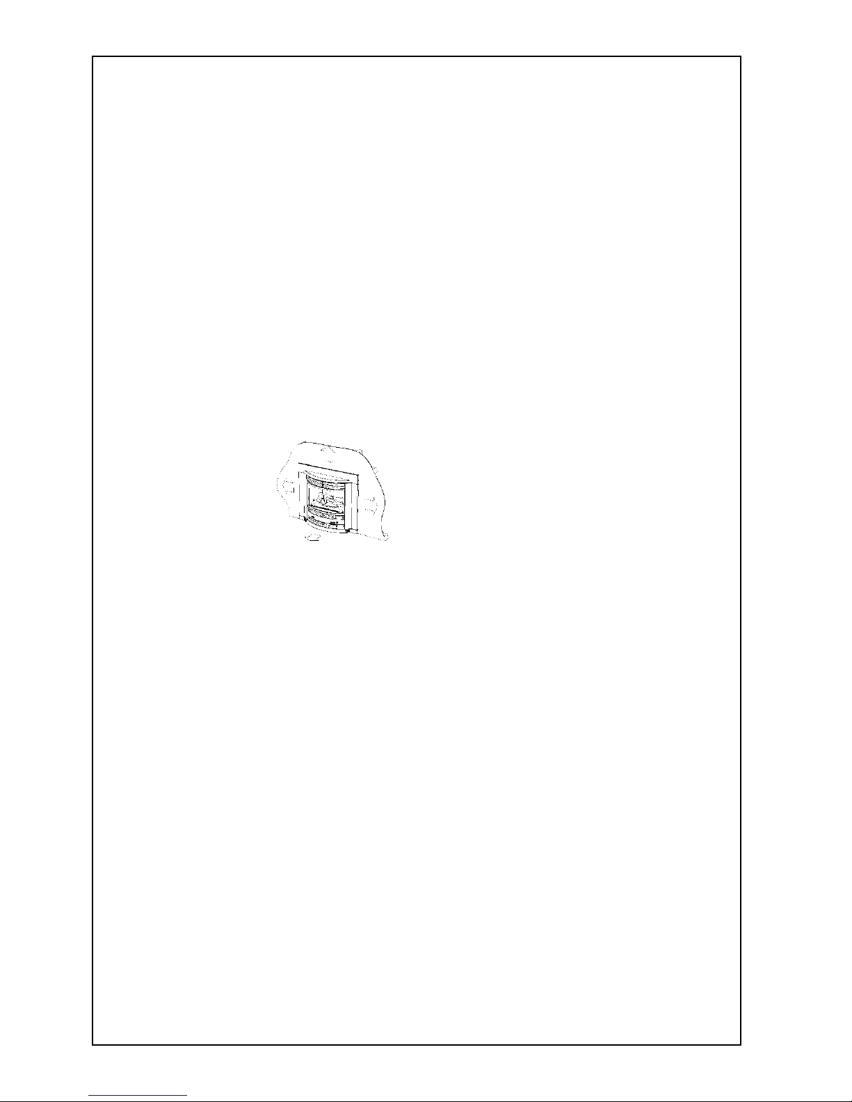
Inbuilt Fire
Table of Contents
Limited warranty ............................................................................................................ 2
Contacts ........................................................................................................................ 3
Specifications ................................................................................................................ 4
Dimensions ................................................................................................................... 4
Important points / usage and installation musts ............................................................... 5
Technical specifications ................................................................................................. 7
For your safety read before operating heater .................................................................. 8
Operation....................................................................................................................... 9
Location......................................................................................................................... 10
Venting .......................................................................................................................... 12
Gas connection .............................................................................................................. 12
Electrical connection ...................................................................................................... 13
Log installation ...............................................................................................................14
Testing and commissioning ............................................................................................ 15
Maintenance instructions ................................................................................................ 16
Wiring diagram .............................................................................................................. 18
Trouble shooting ............................................................................................................ 18
Exploded diagrams........................................................................................................ 19
Parts List ....................................................................................................................... 21
Installation notes ............................................................................................................ 22
Installation / commissioning checklist ............................................................................. 23
Installer details ............................................................................................................... 23
CONTACTS
zx
America Corporation
103 International Drive
Peachtree City
Georgia 30269
This manual applies to the following models only:
IB35RBN/US
IB35RBL/US
1-800-621-9419
www.rinnai.us
4
Model: IB35RBN/US (NG) United States
IB35RBL/US (Propane) United States
Description: Inbuilt radiant/convector, glass-fronted, ceramic log space heater
with fan forced convection and natural draft flue system
Output: 26,000 Btu/hr Natural Gas 23,000 Btu/hr Propane
Gas Control: Push button combination control valve
Burners: Ember bed, flame and heat burner
Warm Air Discharge: Top front louvres
Flue: Natural draft. Approved B vent system
Ignition: Electronic spark
Power Supply: 115v. 60Hz
Rating Plate Location: Bottom right hand side door, inside
Weight: 119 lb
SPECIFICATIONS
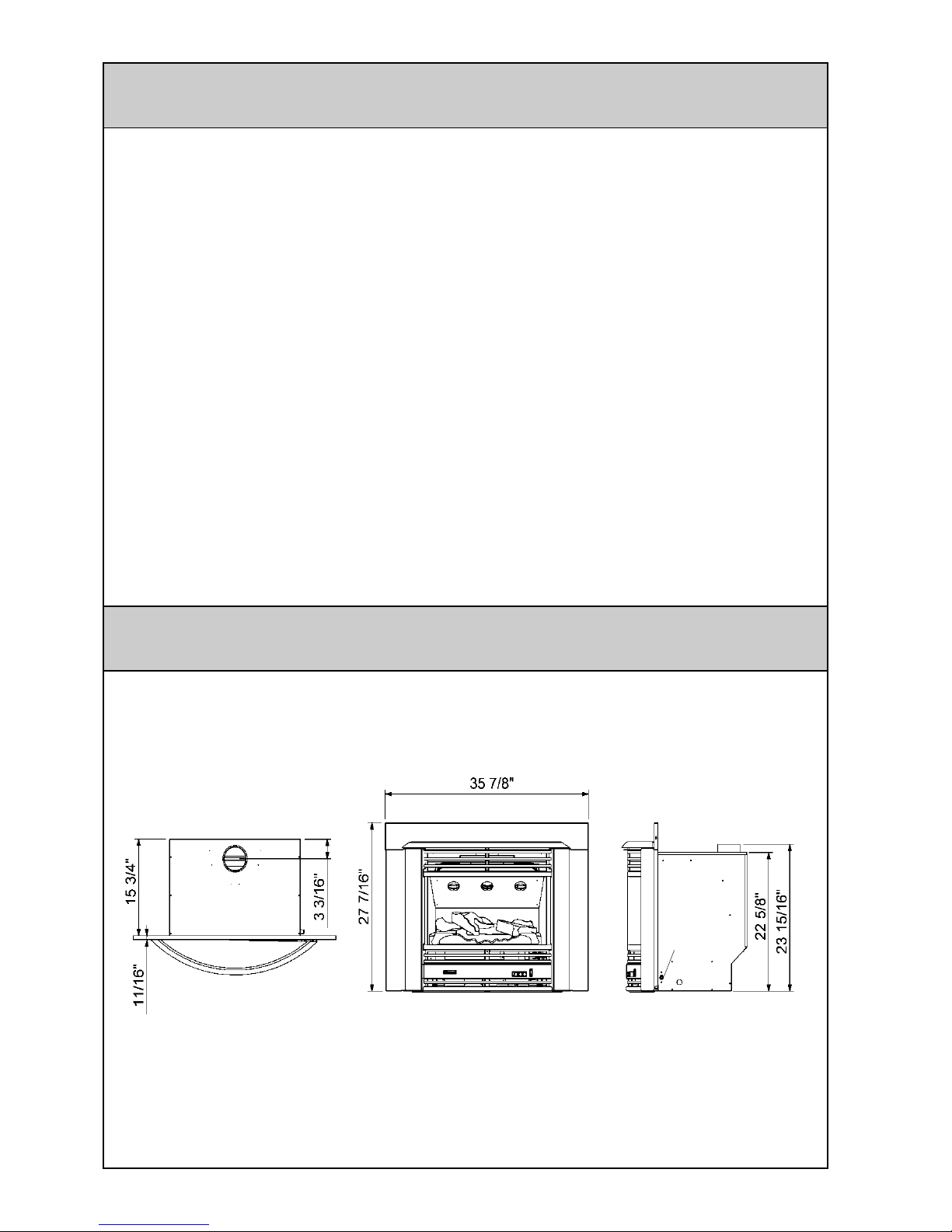
DIMENSIONS
Gas inlet
3/8” MNPT

5
7 Read these rules and the instructions
carefully. Check all local codes. Failure
to follow these could cause a malfunction
of the heater resulting in death, serious
bodily injury and/or property damage.
8 This appliance is only for use with the
type of gas indicated on the rating plate.
This appliance is not convertible for use
with other gases.
9 WARNING: Any change to this heater
or its controls can be dangerous.
10 If a gas leak is suspected, turn heater
off, turn gas supply valve off at appliance
connector valve. Open windows to
ventilate area immediately and contact
your dealer or gas company.
11 DO NOT PLACE CLOTHING OR
FLAMMABLE MATERIALS,
GASOLINE AND OTHER FLAMMABLE
VAPORS AND LIQUIDS, ON OR NEAR
THE HEATER.
12 Do not spray aerosols when the heater
is in operation.
13 YOUNG CHILDREN SHOULD BE
CAREFULLY SUPERVISED WHEN
THEY ARE IN THE SAME ROOM WITH
THE HEATER.
14 LPG containers must not be installed
indoors.
Unpack the heater and check for damage (DO NOT INSTALL DAMAGED HEATER). If the
heater is damaged, contact your supplier for advice. Before installing the heater, check the
label for the correct gas type (see rating plate, bottom right hand side of pillar). Refer to local
gas authority for confirmation of the gas type if you are in doubt.
Included in the carton
Customer operation information
IMPORTANT
Before using this product, please read this manual carefully to make sure of proper use of the
product:
1 The installation must conform with local
codes, or in the absence of local codes,
the National Fuel Gas Code, ANSI
Z223.1, or the Canadian Installation
Code, CAN/CGA -B149.
2 For information on gas type see the data
plate on the appliance.
3 This heater must not be installed where
curtains or other combustible materials
could come into contact with it. In some
cases curtains may need restraining.
4 If you move, check the gas type in the
area where you are moving to. The local
gas authority will be able to advise on
local regulations.
5 This heater discharges a large volume
of warm air to provide even heat
distribution. If the air in the room
contains cooking vapor or cigarette
smoke, and the heater is used on a
carpet, the surface of the carpet may
become discolored. In addition, some
nylon carpets contain dyes which may be
affected by the warm air flow. Some soft
vinyl surfaces are also subject to
distortion, or discoloration by warm air.
To prevent discoloration of carpets, etc.,
a mat should be placed in front of the
appliance, extending about 30” in front
of it.
6 This heater must be installed on a hearth
at least 2” thick and the width and depth
of the heater.
IMPORTANT POINTS / USAGE AND INSTALLATION MUSTS
6
Diagram shows
minimum
clearances from
combustible
materials. (Shown
15 Do not use this appliance if any part has
been under water. Immediately call a
qualified service technician to inspect
the room heater and to replace any part
of the control system and any gas control
which has been under water.
16 Adequate clearances for accessibility for
purposes of servicing and proper
operation should be provided.
17 Adequate clearances around air
openings into the combustion chamber
should be provided.
18 Do not install in areas where curtains,
drapes, clothing, or other moving
flammables are within 15 inches of this
unit.
The appliance must be isolated from the
gas supply piping system by closing its
equipment shutoff valve during any
pressure testing of the gas supply piping
system at pressures equal to or less than
½ psi (3.5 kPa).
23 The draft hood on the appliance should
be installed in the same atmospheric
pressure zone as the combustion air inlet
to the appliance and shall be located so
that the relief opening is accessible for
checking vent operation.
24 The appliance, when installed, must be
electrically grounded in accordance with
local codes or, in the absence of local
codes, with the National Electrical
Code, ANSI/NFPA 70, or the Canadian
Electrical Code, CSA C22.1
25 A gas appliance must not be connected
to a chimney flue serving a solid fuel
burning appliance.
26 Do not restrict the war air discharge by
placing articles in front of heater.
27 This appliance must not be used for any
purpose other than heating.
28 Do not allow anyone to post articles
through the louvres.
29 Do not allow anyone to sit or lean
against the appliance.
30 DUE TO HIGH TEMPERATURES, THE
APPLIANCE SHOULD BE LOCATED
OUT OF TRAFFIC AND AWAY FROM
FURNITURE AND DRAPERIES.
31 CHILDREN AND ADULTS SHOULD BE
ALERTED TO THE HAZARDS OF
HIGH SURFACE TEMPERATURES
AND SHOULD STAY AWAY TO AVOID
BURNS OR CLOTHING IGNITION.
32 CLOTHING OR OTHER FLAMMABLE
MATERIAL SHOULD NOT BE PLACED
ON OR NEAR THE APPLIANCE.
19 Periodic examination of the venting
system is required.
20 The flow of combustion and ventilation
air should not be obstructed.
21 A manufactured home (USA only) or
mobile home OEM installation must
conform with the Manufactured Home
Construction and Safety Standard, Title
24CFR, Part 3280, or, when such a
standard is not applicable, the Standard
for Manufactured Home Installations,
ANSI/NCSBCS A225.1 or Standard for
Gas Equipped Recreational Vehicles
and Mobile Housing, CSA Z240.4.
22 The appliance and its appliance main
gas valve must be disconnected from the
gas supply piping system during any
pressure testing of that system at test
pressures in excess of 1/2 psi (3.5 kPa).
in a zero clearance kit
installation)
12”
RIGHT
12”
ABOVE
40”
FRONT
12”
LEFT

7
TECHNICAL SPECIFICATIONS
33 INSTALLATION AND REPAIR SHOULD
BE DONE BY A QUALIFIED SERVICE
PERSON. THE APPLIANCE SHOULD
BE INSPECTED BEFORE USE AND
AT LEAST ANNUALLY BY A
PROFESSIONAL SERVICE PERSON.
MORE FREQUENT CLEANING MAY
BE REQUIRED DUE TOO
EXCESSIVE LINT FROM CARPETING
BEDDING MATERIAL, ET CETERA. IT
IS IMPERATIVE THAT CONTROL
COMPARTMENTS, BURNERS AND
CIRCULATING AIR PASSAGEWAYS
OF THE APPLIANCE ARE KEPT
CLEAN.
34 The glass window shall be replaced as
one piece as supplied by the
manufacturer. See glass and log
installation on page 14
35 Do not substitute glass, glowing embers
or logs. Use only glass, glowing embers
and logs supplied by manufacturer.
36 Caution: Do not operate unit with broken
glass.
37 WARNING: DO NOT OPERATE
APPLIANCE WITH THE FRONT
REMOVED, CRACKED OR BROKEN.
REPLACEMENT OF THE GLASS
SHOULD BE DONE BY A LICENSED
OR QUALIFIED SERVICE PERSON.
Natural Gas Propane
Gas Input Rate: Btu/hr Btu/hr
Pilot: 200 200
13,000 11,000
High: 34,000 31,000
WC WC
Min: 7" 10"
Max: 10.5" 13"
Gas C onnection:
Flue Termination:
Fan:
Combustion System:
Logs: Ceramic
Ignition System:
Operation:
Safety Devices:
Fan delay Bi-metal strip
Combustion Method:
Flue Type:
Heat transfer:
Installation Type:
Flue Requirement:
Minimum permissible
gas supply pressure
for purpose of input
adjustment
Manufacturers minimum, 10 ft vertical.
Local codes may have a greater
requirement and must be followed
Flame failure thermocouple
Over heat Bi-metal strip
Inbuilt
Naturally aspirated burner
B vent
Direct radiation and forced convection
3/8" MNPT
Push button to light pilot and main burners
An approved 4" vent cap must be fitted to all installations
90 Watt 2 speed tangential
Multi port burner
Continuous spark electroni c igniti on
8
A This appliance is equipped with an
ignition device which automatically
ignites the pilot. Do not try to light the
pilot by hand.
B. BEFORE OPERATING smell all around
the appliance area for gas. Be sure to
smell next to the floor because some
gas is heavier than air and will settle on
the floor.
WHAT TO DO IF YOU SMELL GAS
• Do not try to light any appliance.
• Do not touch any electrical switch.
• Do not use any phone in your building.
• Immediately call your gas supplier from
STOP Read the safety information
above.
• To turn the unit on (Refer to diagram
below)
WARNING: If you do not follow these instructions exactly, a fire or explosion
may result causing property damage, personal injury or loss of life.
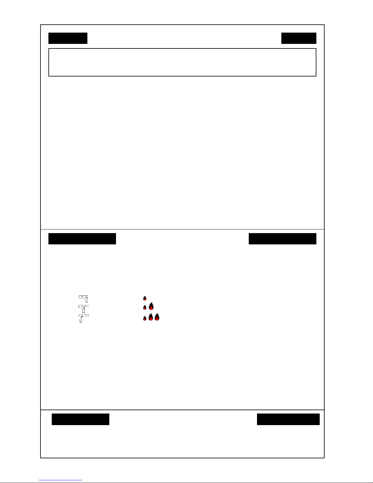
1. Pilot Off/Low
2. Low Off/Low/High
3. High High (Auto)
SETTING BUTTONS FAN BURNER
FOR YOUR SAFETY READ BEFORE OPERATING
a neighbour’s phone. Follow the gas
suppliers instructions.
• If you cannot reach your gas supplier call
the fire dept.
C. Use only your hand to push the gas
control buttons. Never use tools. If the
buttons will not activate by hand, don’t
try and repair it, call a qualified service
technician. Force or attempted repair
may result in a fire or an explosion.
D. Do not use this appliance if any part has
been under water. Immediately call a
qualified service technician to inspect
the appliance and to replace any part
of the control system and any gas control
which has been under water.
OPERATING INSTRUCTIONS
Visually check the pilot has lit and continue
to hold the button for up to 15 seconds.
If the pilot does not remain alight, push the
button again and release it. This will return
it to the off position. Wait 30 seconds and
repeat the ignition procedure.
• To turn on the heat
Press the center button, this will ignite the
front burner, then press the remaining button
to ignite the main burner.
• To decrease the heat
Release the last two control buttons in the
reverse order.
• To turn the unit off
Release all three buttons to the off position.
Place the gas control in the off position (all
buttons up / out) and turn off the power at
the switch.
TO TURN OFF GAS TO APPLIANCE
Do not attempt to light the pilot by hand.
Wait for five minutes to clear out any gas.
Then smell for gas, including near the
floor. If you smell gas, STOP! Follow
“B” in the safety information. If you don’t
smell gas, go to the next step.
Press the first control button firmly. This
operates the built in safety device and
starts the electronic spark.
Disconnect the electric plug. This will
prevent accidental ignition if the gas
control valve is operated.
 Loading...