

Page 1
Flame Fire
Operating and Installation Instructions
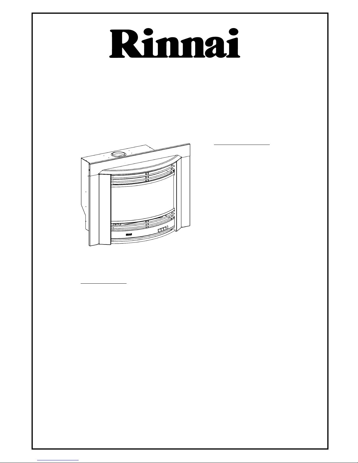
Inbuilt Royale (Australia)
Timberflame IB35R (New Zealand)
Table of Contents
Customer Instructions
Operation
Safety Points
Troubleshooting
Installation Instructions
Location
Flueing
Gas Connection
Log Installation
Testing & Commissioning
Technical Data
Service Contacts
Installation Checklist
Installer Details
IMPORTANT
This appliance shall be installed in accordance with:
•Manufacturers Installation Instructions.
• Local Gas fitting regulations.
• Municipal Building codes.
• AGA Gas Installation Code AG601 - NZ 5261.
• Any other relevant statutory regulation.
• Rinnai strongly recommend that this product be installed with an
approved flue system for optimum product performance.
• This appliance must only be installed, serviced and removed by an
authorised person.
• For Australian installation, this appliance must be installed with
the supplied wire dressguard.
This heater is NOT designed to be built directly into any combustible
opening.
For combustible opening installations, a Rinnai Zero Clearance Kit is
available from your Gas Appliance Retailer.
2
3
4
5
6
8
9
10
11
11
12
12
Page 2
YOur
LOCATION
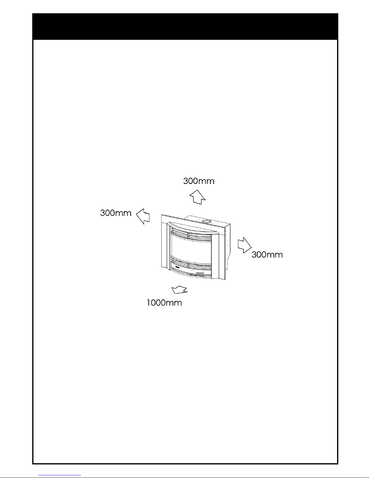
When positioning the heater, the main points governing the location are:
1. Flueing.
2. Warm air distribution.
3. The heater must not be installed where curtains or other combustible materials could come
into contact with it. In some cases, curtains may need restraining.
See below for minimum clearances required.
4. The heater is not designed to be built into bookcases or shelves or any combustible
opening.
5. Under no circumstances must combustible materials be present on the inside of the
fireplace recess or flueway.
Note: A Rinnai Zero Clearance kit is available where the heater is required to be installed
in close proximity to combustible framing.
6. The heater must be mounted on a hearth no less than 50mm. high and the width and
depth of heater.
7. Check that room ventilation complies with local regulations.
8. Check that an EARTHED power point is within 1500mm. of the right hand side of the
heater.
5
Your new Flame Fire is designed to be installed in a masonry fire place.
The appliance can also be built into a non-masonry application by installing a
Rinnai Zero Clearance box and an approved flue system.
Page 3
FLUEING
6
Rinnai strongly recommends that this appliance be installed with an approved
flue liner system in all installations.
Installation without a flue liner is however permissible into masonry chimneys only after physical inspection
and testing of the chimney to set criteria. Installation of this appliance into a chimney that fails to meet this
criteria will not only void the product warranty, but is highly likely to impede product performance.
The following criteria must be met in all cases:-
Internal Criteria:
• Allow sufficient height above the firebox to enable the debris diverter (See page 8) to be fully operational
(ie. open 45°). Failure to do so will result in incomplete combustion and emissions discharged into the
room.
• All loose/broken bricks must be repaired ensuring the chimney is of sound construction and free from
leakage. Failure to do so may result in emission discharge into the room.
• The chimney must be free of soot and creosote accumulation resulting from previous slow combustion
wood fires. It must also be clear of all blockages and swept prior to installation.
• Any damper plate must be fixed in the open position or removed.
• Any underfloor air supply to the fireplace must be completely sealed off to prevent secondary air draw.
External Criteria:
• An approved chimney cap and cowl must be installed with this appliance. If there is an existing cap, it must
be free of defects/deterioration and repaired if found to be faulty.
• Inadequate chimney height can also effect product performance. Some applications may require the
chimney height to be extended to reduce possible down drafts.
• A flue draft smoke test must be carried out to confirm that an updraft occurs and the flue system is sound.
There must be no leakage of smoke through the structure of the chimney during or after the test. Inside,
upstairs and/or adjacent rooms should also be checked.
If any of the above criteria is not met, a Rinnai approved flue liner system
must be installed.
Page 4

•CHECK DIMENSIONS OF FIREPLACE
Check dimensions of fireplace and if necessary
bring them to dimensions shown.
• CHECK FLUEWAY
Check flueway is clear of obstructions.
Provide a firm, flat and sealed base for unit.
Sealed means no holes or openings in fireplace.
A rough base may affect the performance of this unit
CHIMNEY INSPECTION
A. Improper chimney height.
B. Chimney Cap deterioration.
C. Creosote stains.
D. Blockage within flue.
E. Clearance to combustibles.
F. Soot / Creosote accumulation.
G. Structural deterioration.
H. Loose or broken bricks.
I. Smoke Pellet test. (Leakage)
FLUEING
• SEALING THE INBUILT
INSTALLATION
Peel protective backing off the foam strips supplied
with the heater. Attach strips to rear of casing as
shown.
The strip is intended to form a seal between the
heater and fireplace. If an adequate seal cannot be
formed with this strip, another means of sealing must
be used (eg. non-combustible insulation), between
the fireplace and the heater body.
7
SEALING STRIPS
Note: Brackets are supplied to retain the heater
to the fireplace and must be attached prior to
installation as shown in the diagram.
.
Page 5

8
• RUN GAS SUPPLY
For pipe sizing, refer to your local gas installation codes.
Copper supply should be run leaving the end of the pipe in a
suitable position to be able to attach to the stainless steel flexi- tube
and the 1/2” BSP male union provided.
(refer diagram)
PURGE SUPPLY OF AIR AND SWARF.
All foreign materials such as filings must be purged from the gas
supply, as they may cause the gas valve to malfunction.
• SLIDE HEATER INTO FIREPLACE
Slide the heater carefully into position, while feeding the stainless
steel flexi-tube through the supply access opening at right hand rear.
NOTE: A spring-loaded flue protector plate is fitted to
prevent the entry of foreign objects for a masonry
chimney installation.
The plate will fold down as the heater slides through the
fireplace opening.
IMPORTANT: Make sure that the flue protector plate is not
restricted and returns to its normal position when the heater
is installed.
If the fire has to be removed, the plate will pivot
backwards to allow the heater to slide clear.
When a flue liner or Zero Clearance Box is used,
the flue protector plate must be unscrewed and removed.
Secure the heater to the fireplace. There are pre-drilled holes in the
heater surround behind the doors. Drill additional holes if the
existing ones are not in suitable positions.
Refer to Page 9 for removal and replacement of logset.
Remove the front and middle burners by undoing the left hand end
screws, sliding the burners to the left, and lifting out.
Slide out and remove the bottom louvre rods which are
held in place by tension.
Carefully remove the screws from both ends of the front panel.
Remove the top and bottom screws from the centre louvre rod
retaining bracket.
Slide out the fan partition tray exposing the gas control and
flare connection.
Bend the flexi-tube and connect to the gas control valve.
Check for gas leaks.
Replace and refit all parts that have been removed in reverse order.
On completion of all work, check all connections for gas leaks.
GAS CONNECTION
Page 6
LOG INSTALLATION
The logset is packed inside the heater and the packaging must be removed prior to
installing the logset in its correct position.
• Open both side panels.
• Remove fastenings on both sides of the
top glass retainer.
Lift retainer away from heater.
• Loosen screws on bottom glass retainer.
Carefully lift glass out of bottom channel.
• Carefully remove log packaging.
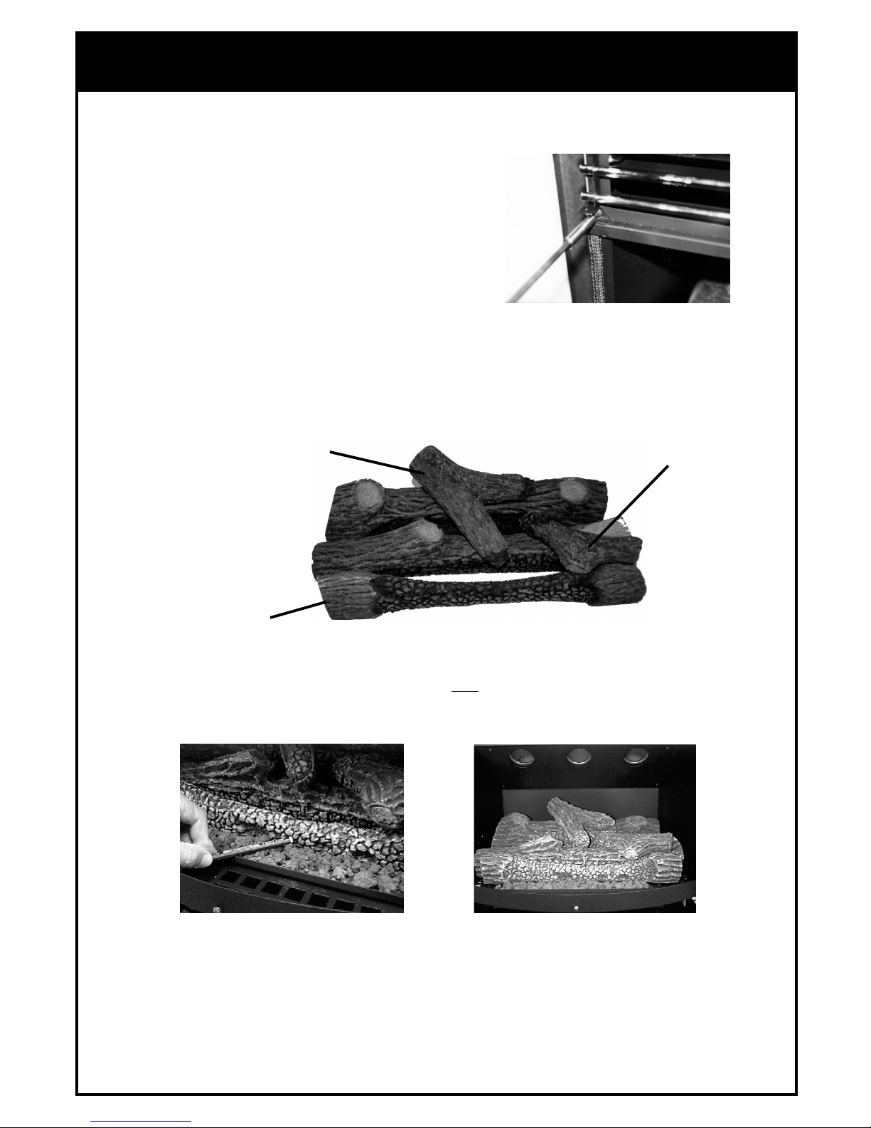
The logset consists of a Main Log which has four pins on the top, for the location of the Top and Right Logs
and two holes underneath for location onto the pins inside the heater.
Place the logset into the heater ensuring that the locating pins enter the two locating holes on the
bottom face of the logset, if not already attached.
Carefully position the Top Log and the Right Log on the locating pins of the Main Log as shown.
Gently place loose ember bed material in front of the front log. Do not pour as dust particles from
the plastic bag may block the burner ports. Level it with a pencil or screwdriver and remove excess
material. Note: The ember bed material must be placed after the logs are fitted. If the logs are to be removed
for any reason, the ember bed material must be removed first and replaced after the logs are refitted. Any
material that prevents the logs sitting flat on the burner top can upset the burning pattern and performance
of the heater.
• Replace glass and top glass retainer, tighten bottom glass retainer screws.
• Note: Fit glass so that the join/gap in the glass seal is at the bottom.
• Take care not to damage seals.
• Reinstall side panels.
Top Log
Right Log
Main Log
Note: When first lighting the heater, the logs need to be burnt in, which may take approximately 2
hours. The flame colour may change after the initial burning in period.
vvvvv
9
Page 7

Comple
TESTING & COMMISSIONING
TESTING PROCEDURE
Turn gas supply on and plug the unit into the power supply. (Caution 240V.)
•TO CHECK BURNER PRESSURE
• Refer to Data Plate.
• The test point is located on the gas control valve which is
attached to the control buttons, behind the lower front panel.
• Remove test point screw and attach manometer to test point.
The test point is on the front side of the gas valve.
Light heater, push control buttons to the high position and
check pressure.
• If adjustments are necessary, the regulator is situated on
the front of the gas control.
• After checking pressure, turn the unit off, remove manometer and replace test point screw.
• Turn the heater on and off a few times to check ignition.
• When you are satisfied that the heater is working correctly, reassemble panels.
• All burner aeration is factory preset and cannot be adjusted.
• If you are unable to get the unit to operate correctly, refer to Troubleshooting on Page 4,
before contacting your local service agent as listed on Page 11.
• It may take approximately 2 hours for the logs to achieve their full flame pattern and glow.
• During the initial burning in period, some smoke and smell may be experienced. The
heater should be run on the high position in a well ventilated room until these dissipate.
•INSTRUCT CUSTOMER ON USE OF UNIT
Explain to customer about use and care of unit. Make sure the customer understands the instructions.
• EXPLAIN
Ignition, Adjusting heat level, Fan Switch, Turning “OFF”.
COMMISSIONING
10
• INSTALLATION AND COMMISSIONING CHECKLIST
Complete the installation / commissioning checklist and the installer / gasfitter details on page 12 and
make sure that this instruction book is left with the customer.
NOTE:
RINNAI RESERVES THE RIGHT TO CHANGE OR MODIFY SPECIFICATIONS WITHOUT NOTICE.
Page 8

Comple
Model:
Description:
Input:
Gas Control:
Burner:
Gas Inlet:
Test Point Pressure:
Flue:
Flue Termination:
Ignition:
Power Supply:
Fan:
Data Plate:
TECHNICAL DATA
FGL30 IDBN (NG) Australia
FGL30 IDBL (Propane) Australia
IB35RN (NG) New Zealand
IB35RL (Propane) New Zealand
Rinnai Inbuilt Radiant/Convector, glass-fronted, ceramic log space heater
with forced convection and natural draught flue system.
33 MJ/h Natural Gas and Propane.
Rinnai Push-Button Combination Control.
Ceramic Logs, Ember Bed and Heat Burner.
15mm. Copper Flare Connection.
Natural Gas 0.95 kPa; Propane 2.40 kPa.
Natural Draught.
An approved 100mm. cowl must be fitted
to all installations.
Electronic Spark.
230/240v. 50Hz unit is supplied with 3 pin
plug and supply lead, replace only with
Rinnai P/N 90179599(Aust.) 6765B(NZ).
Tangential 2 Speed, Watt Rating 90W.
Inside right hand side panel.
11
SERVICE CONTACT POINTS
RINNAI AUSTRALIA PTY. LTD. ACN. 005 138 769
Helpline: 1300 366 388
Mon.-Fri (8.30am-5.30pm EST)
(Cost of a local call - higher from mobile or public phones)
Internet: www.rinnai.com.au
Email: enquiry@rinnai.com.au
Head Vic./Tas. 10-11 Walker St. Braeside, Vic. 3195
Office: Tel.(03) 9271 6625 Fax.(03) 9271 6622
Sales Tel.(03) 9271 6666 Fax.(03) 9271 6611
Service Tel.(03) 9271 6699 Fax.(03) 9271 6688
NSW/ACT: 62 Elizabeth St. Wetherill Park, NSW 2164
Tel. (02) 9609 2888 Fax. (02) 9729 5260
SA./NT: 140 Days Rd. Ferryden Park, SA. 5010
Tel. (08) 8345 0292 Fax. (08) 8345 4760
WA: 18 Belgravia St. Belmont, WA. 6104
Tel. (08) 9478 3355 Fax. (08) 9277 2531
QLD: 1/6 Booran Drive, Logan Central, Qld. 4114
Tel. (07) 3209 4622 Fax. (07) 3209 4722
RINNAI NEW ZEALAND LTD.
Internet: www.rinnai.co.nz
Email: info@rinnai.co.nz
691 Mt. Albert Rd. Royal Oak, Auckland, NZ.
PO Box 24-068 Tel. (09) 625 4285 Fax. (09) 624 3018
24 Hr. Service Tel. 0800 746624 (0800 Rinnai)
Page 9

12
INSTALLATION / COMMISSIONING CHECKLIST
(To be completed by certified Gas Installer)
Model: ____________________
1. Was a fireplace inspection carried out?
(ie. clearances, combustibles etc.)
2. Was chimney inspected?
3. Did chimney require flue liner system to be installed?
If NO, did chimney meet specified criteria as per manual?
4. Has specified gas pressure been set?
5. Are decorative logs located correctly on pins?
6. Have ember granules been placed and free of dust and powder?
7. Has appliance been sealed around the fireplace?
8. Has the appliance been commissioned?
9. Is the end-user fully aware of operating procedure?
NO
YES
INSTALLER / GASFITTER DETAILS
Company Name: ____________________________________________________________________
Gasfitters Name: ____________________________________________________________________
Address:____________________________________________________________________________
____________________________________________________________________________
Phone: __________________________
Mobile: ____________________________
Certificate of Compliance / Certification Number: ______________________________________
Signed: _________________________________ Date: ______________________________
Part Number 7290
 Loading...