

Rinnai HSNRA80, HINRA35M, HINRA26M, HINRA50M, HINRA70M Installation Manual
...
This appliance shall be installed in accordance with:
• Manufacturer’s Installation Instructions
• Current AS/NZS 3000
• Local Regulations and Municipal Building Codes including local OH&S requirements
This appliance must be installed, maintained and removed by an Authorised Person.
For continued safety of this appliance it must be installed and maintained in
accordance with the manufacturer’s instructions.
Installation Manual
Split Type Wall Mounted Air Conditioner
HINRA26M
HINRA35M
HINRA50M
HINRA70M
HINRA80
HSNRA26
HSNRA35
HSNRA50
HSNRA70
HSNRA80
HONRA26
IndoorSystem Outdoor
HONRA35
HONRA50
HONRA70
HONRA80
Rinnai System Models
HINRA20MReference Only Matching Multi System Only
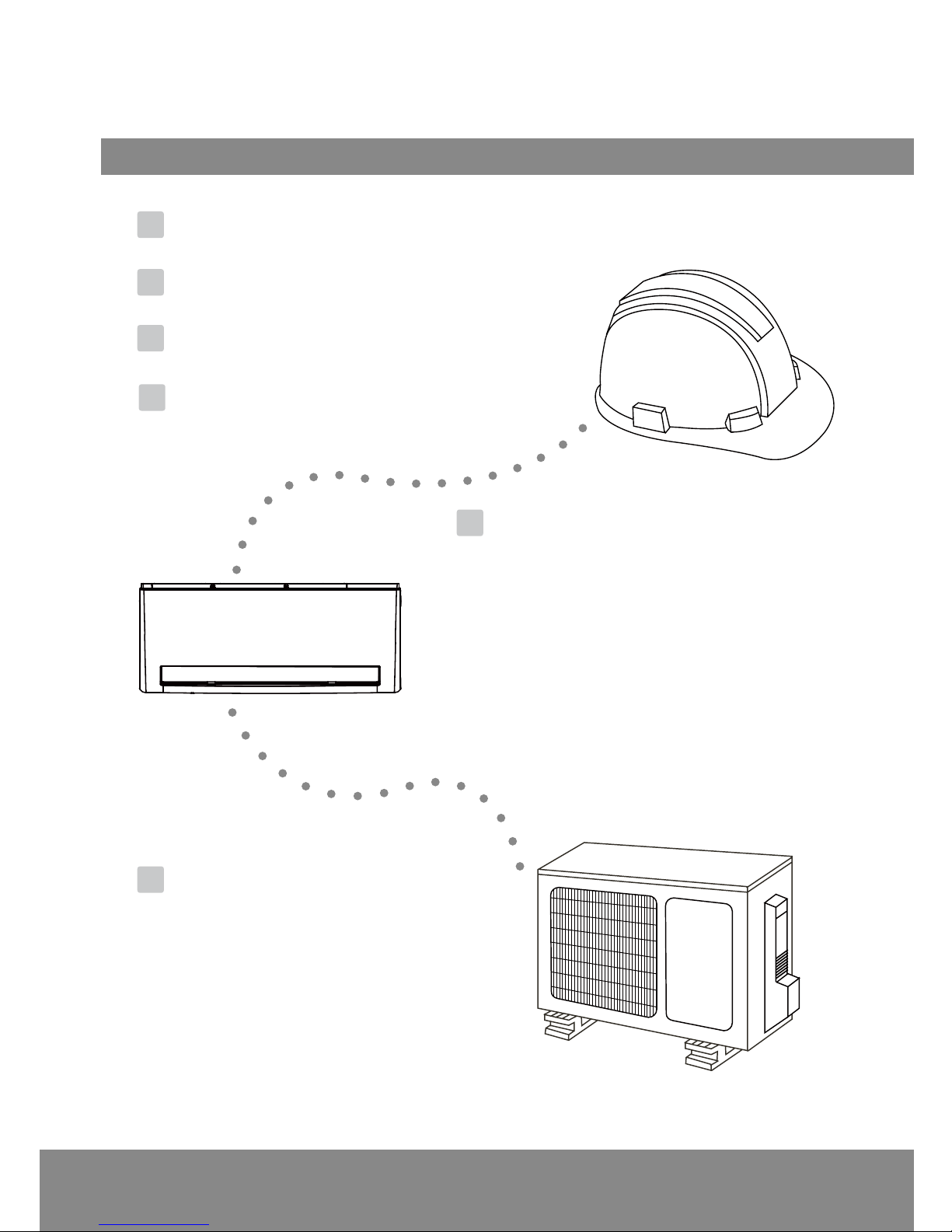
Table of Contents
Installation Manual
Indoor Unit Installation
.........
11
1. Select installation location ......................... 11
2. Attach mounting plate to wall ................ 12
3. Drill wall hole for connective piping ...... 12
4. Prepare refrigerant piping ......................... 14
5. Connect drain hose ..................................... 15
6. Connect signal cable .................................. 17
7. Wrap piping and cables ........................... 18
8. Connect indoor power wire ................... 18
9. Mount indoor unit ..................................... 18
Outdoor Unit Installation
.. 20
8
1. Select installation location ............... 20
2. Install drain joint ................................. 21
3. Anchor outdoor unit ......................... 22
4. Connect signal and power cables .. 23
Safety Precautions ................................... 4
0
1
5
Accessories
..................................................
6
2
4
Unit Parts
..................................................
10
3
Installation Summary - Indoor Unit
.......
All pictures for illustrative purposes
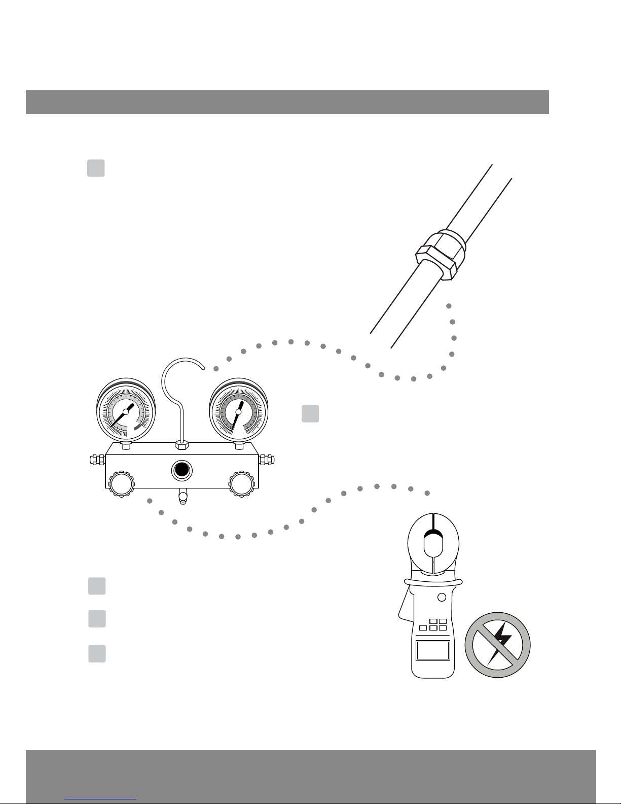
Refrigerant Piping Connection
........
25
A. Note on Pipe Length ............................................................. 25
B. Connection Instructions –Refrigerant Piping ............... 25
1. Cut pipe ............................................................................... 25
2. Remove burrs ..................................................................... 26
3. Flare pipe ends ................................................................. 26
4. Connect pipes .................................................................... 27
Air Evacuation
.......................
29
1. Evacuation Instructions .......................... 29
2. Note on Adding Refrigerant ................ 30
Electrical and Gas Leak Checks
.........
31
Test Run
....................................................
32
Disposal Guidelines .............................. 34
6
7
8
9
10
MC MC
Page 4
Safety Precautions
READ ALL INSTRUCTIONS BEFORE USING THE APPLIANCE
Always comply with the following precautions to avoid dangerous situations and to ensure optimum
performance. Failure to carefully read and follow all instructions in this manual can result in
equipment malfunction, property damage, personal injury and/or death.
WARNINGS: WHEN IGNORED, CAN RESULT IN SERIOUS INJURY OR DEATH.
CAUTIONS: WHEN IGNORED, CAN RESULT IN MINOR INJURY OR RODUCT DAMAGE.
THIS SYMBOL INDICATES THAT YOU MUST NEVER PERFORM THE ACTION INDICATED.
REGULATORY / INSTALLATION
This appliance shall be installed in accordance with:
Manufacturer’s Installation Instructions.
Current AS/NZS 3000.
Local Regulations and Municipal Building Codes including local OH&S requirements.
This appliance must be installed, maintained and removed by an Authorised Person.
For continued safety of this appliance it must be installed and maintained in accordance with the
manufacturers instructions.
This appliance uses R410A refrigerant.
This appliance is heavy, use 2 people or mechanical lifting device. Improper lifting may result in
serious injury.
Take care when opening or unpacking this appliance. Failure to do so may result in serious injury or
product failure.
DO NOT modify the electrical wiring of this appliance. If the control power wiring is damaged or
deteriorated then it must be replaced by an authorised person. Failure to do so may result in
electric shock, fire, serious injury or product failure.
DO NOT install the air conditioner on an unstable or non level surface or where there may be a
danger of it falling. It may result in death, serious injury, or product failure.
DO NOT install the outdoor unit where noise may cause nuisance.
DO NOT install the outdoor unit where it will be exposed to sea wind (salt spray) as this will reduce
durability.
This manual applies to a 1:1 wall mounted system application.
Several indoor units covered in this manual have an "M" suffix in their Model Number. These units
can also be used on selected Rinnai Multi Split systems applications.
For more information on compatibility, please refer to the Installation Manual accompanying the
Rinnai Multi Split Outdoor Unit.
WARNING
DO NOT modify the length of the power cord or use an extension cord to power the unit.
DO NOT share the electrical outlet with other appliances. Improper or insufficiet power supply
can cause fire or electrical shock
This appliance is NOT intended for use by persons (including children) with reduced physical,
sensory or mental capabilities, or lack of experience and knowledge unless they have been given
supervision or instruction concerning use of the appliance by a person responsible for their
safety. Children should be supervised to ensure that they DO NOT play with the appliance.
Page 5
Safety
Precautions
Warning
1. Installation MUST BE performed by an authorised dealer or specialist. Defective installation can
cause water leakage, electrical shock or fire.
2. Installation MUST BE performed according to the installation instructions. Improper installation
can cause water leakage, electrical shock or fire.
3. Contact an authorised service technician for repair or maintenance of this unit.
4. Only use the included accessories, parts, and specified parts for installation. Using non-standard
parts can cause water leakage, electrical shock or fire, and cause the unit to fail.
5. Install the unit in a firm location that can support the units weight. If the chosen location cannot
support the units weight, or the installation is not done properly, the unit may drop and cause
serious injury or damage.
6. For all electrical work, follow all local and national wiring standards, regulations, and the
installation manual. You MUST use an independent circuit and single outlet to supply power.
DO NOT connect other apppliances to the same outlet. Insufficient electrical capacity or defects
in electrical work can cause electrical shock or fire.
7. For all electrical work, use the specified cables. Connect cables tightly, and clamp them securely
to prevent external forces from damaging the terminal. Improper electrical connections can
overheat and cause fire, and may also cause shock.
8. All wiring MUST BE properly arranged to ensure that the control board cover can close properly.
If the control board cover is not closed properly, it can lead to corrosion and cause the
connection points on the terminal to heat up, catch fire, or cause electrical shock.
9. In certain functional environments, such as kitchens, server rooms, etc., the use of specically
designed air-conditioning units is highly recommended.
10. If the supply cord is damaged, it MUST BE replaced by the manufacturer, its service agent or
similarly qualified persons in order to avoid a hazard.
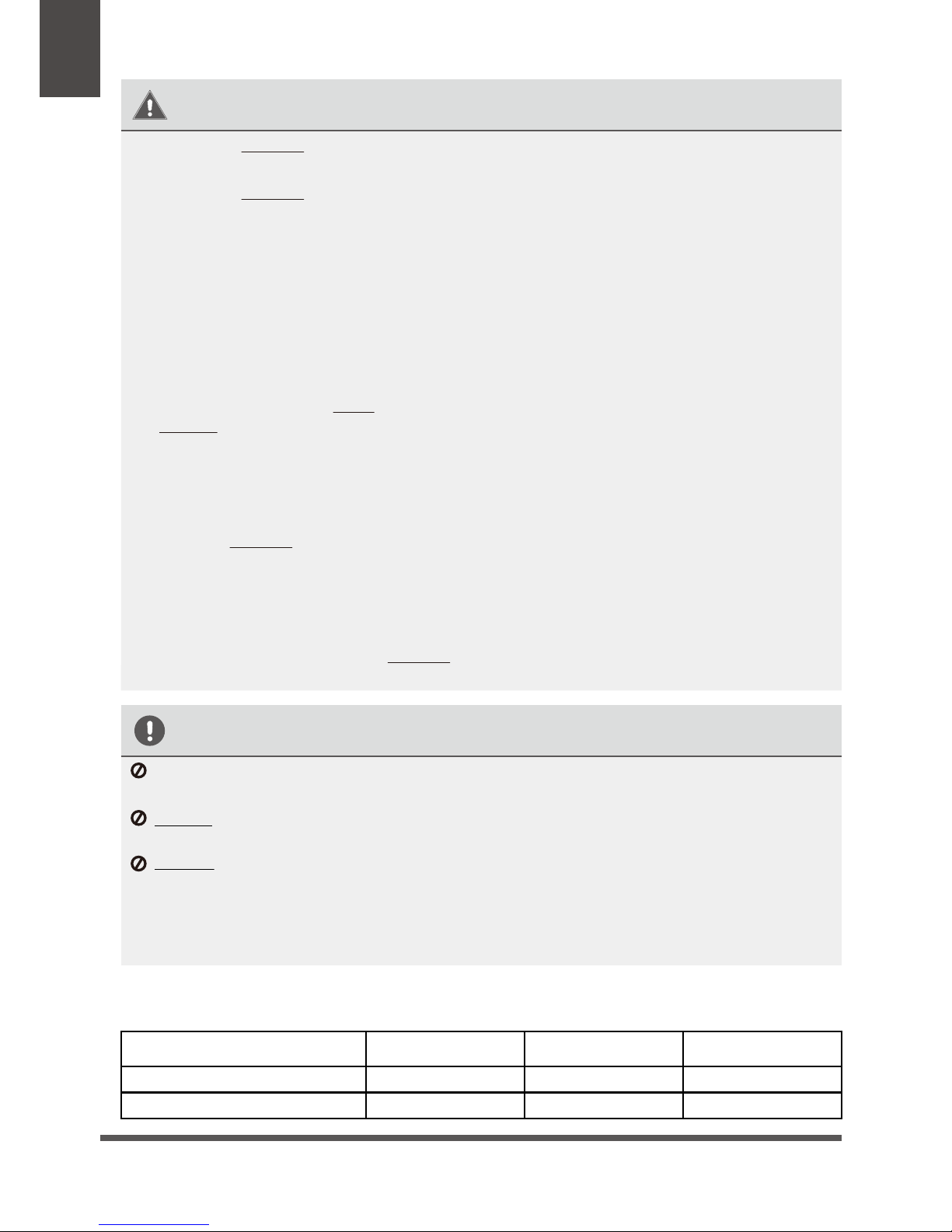
OPERATION RANGE LIMITATIONS
The table below indicates the temperature ranges the air conditioner can be operated within.
COOL Mode HEAT Mode DRY Mode
Room Temperature 0°C ~30°C 10°C ~ 32°C
Outdoor Temperature -15°C ~ 30°C
17°C ~ 32°C
-15°C ~ 50°C 0°C ~ 50°C
CAUTION
For units that have an auxiliary electric heater, do not install the unit within 1 meter (3 feet) of any
combustible materials.
DO NOT install the unit in a location that may be exposed to combustible gas leaks. If combustible
gas accumulates around the unit, it may cause fire.
DO NOT operate your air conditioner in a wet room such as a bathroom or laundry room. Too
much exposure to water can cause electrical components to short circuit.
1. The product must be properly earthed at the time of installation, or electrical shock may occur.
2. Install drainage piping according to the instructions in this manual. Improper drainage may
cause water damage to your home and property.
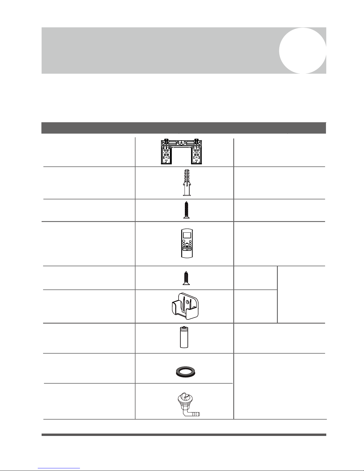
Name
Shape Quantity
1
1
1
(for cooling & heating
models only)
Clip anchor
Mounting plate fixing
screw ST3.9 X 25
Remote controller
Fixing screw for remote
controller holder ST2.9 x 10
Remote controller holder
Dry battery AAA
Seal
Drain joint
Mounting plate
1
Accessories
The air conditioning system comes with the following accessories. Use all of the installation parts and
accessories to install the air conditioner. Improper installation may result in water leakage, electrical shock
and fire, or cause the equipment to fail.
5
5
2
1
Optional
Parts
2
Page 6
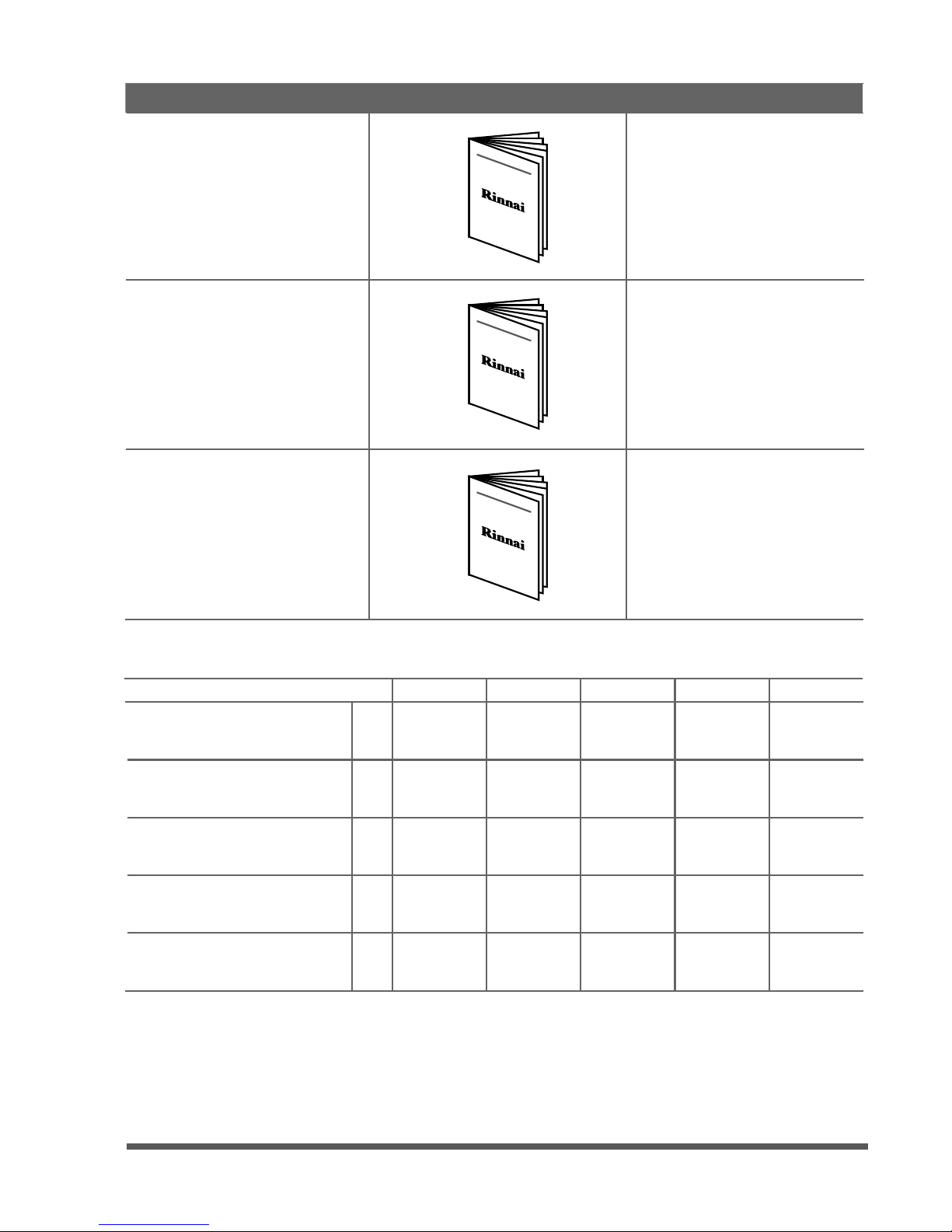
1
1
1
Owner’s manual
Installation manual
Remote controller manual
Page 7
Name
Shape Quantity
HSNRA26 HSNRA35 HSNRA50 HSNRA70 HSNRA80
Pipe Size: Liquid / Gas
mm
Φ 6.35 /
Φ 9.52
Φ 6.35 /
Φ 12.7
Φ 6.35 /
Φ 12.7
Φ 9.52 /
Φ 15.9
Φ 9.52 /
Φ 15.9
Maximum Pipe Length
m
25 25 30 50 50
Chargeless Length
m
55555
Extra Charge for Lengths >5m
g/m
15 15 15 30 30
Maximum Vertical Separation
m
10 10 20 25 25
System
Refrigerant Piping Summary (Field Supplied)
Owners Manual
SPLIT-TYPE ROOM AIR CONDITIONER
SPLIT-TYPE ROOM AIR CONDITIONER
Remote Control Manual
Installation Manual
SPLIT-TYPE ROOM AIR CONDITIONER
Page 8
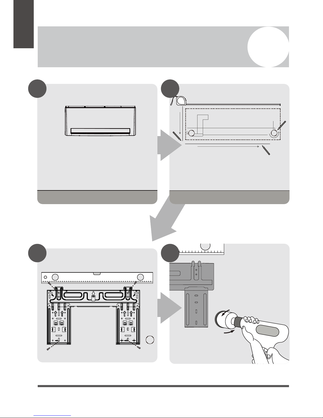
Select Installation Location
Attach Mounting Plate Drill Wall Hole
Installation Summary - Indoor Unit
2
Installation
Overview
Determine Wall Hole Position
1 2
3 4
12cm
(4.75in)
12cm
(4.75in)
15cm (5.9in)
Page 9
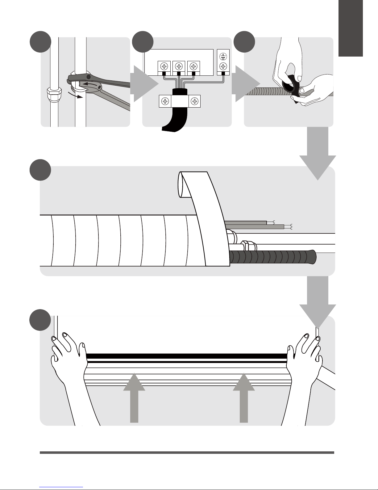
Mount Indoor Unit
STEP
8
Wrap Piping and Cable
1 2 3
Connect Piping Connect Wiring Prepare Drain Hose
5 6 7
8
9
Installation
Overview
Page 10
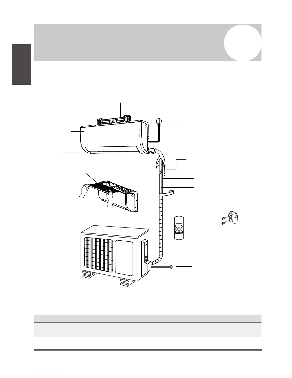
Unit Parts
3
Installation
Overview
Fig.3.1
NOTE ON ILLUSTRATIONS
Illustrations in this manual are for explanatory purposes. The actual shape of your indoor unit may be
slightly different.
Wall Mounting Plate
Power Cable (Where Fitted)
Refrigerant Piping
Signal Cable
Remote Control
Drainage Pipe
Louver
Remote Holder
Front Panel
Outdoor Unit
Power Cable
Air filter
(pull it out)
Page 11
Indoor Unit Installation
4
Installation Instructions – Indoor
Unit
PRIOR TO INSTALLATION
Before installing the indoor unit, refer to the
label on the product box to make sure that the
model number of the indoor unit matches the
model number of the outdoor unit.
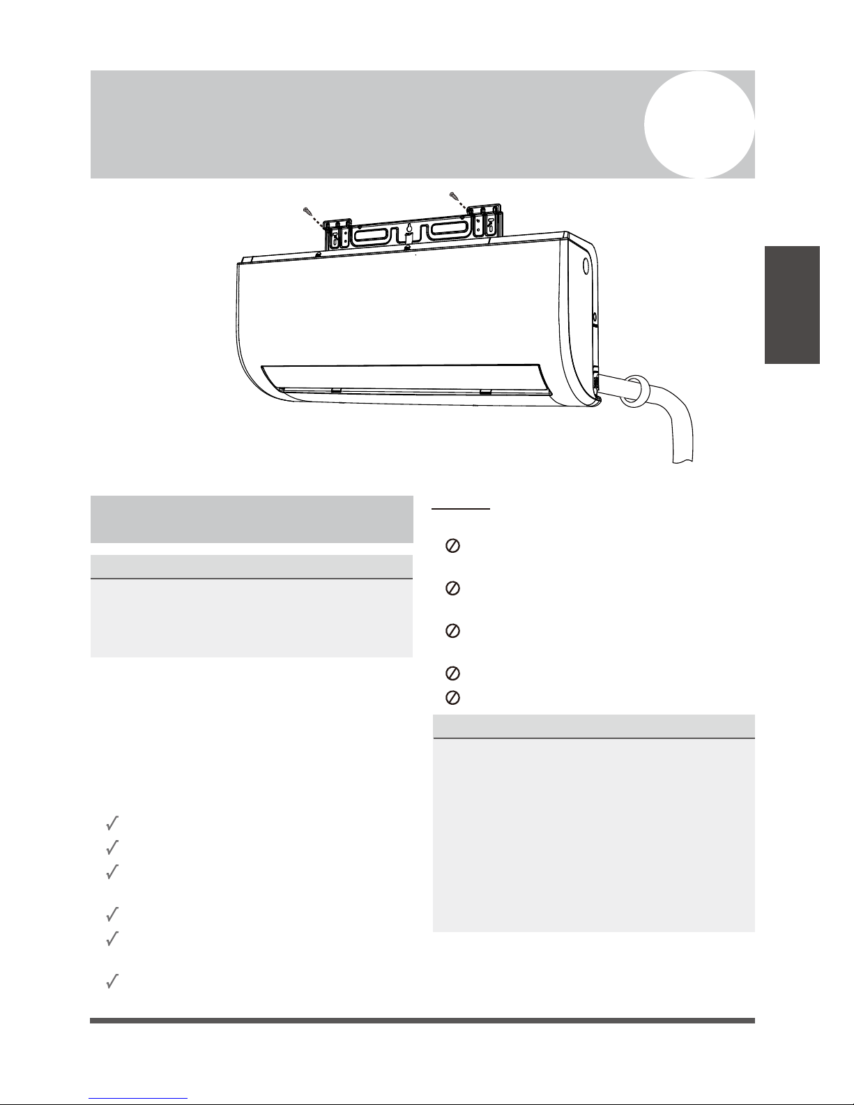
Step 1: Select installation location
Before installing the indoor unit, you must
choose an appropriate location. The following
are standards that will help you choose an
appropriate location for the unit.
Proper installation locations meet the
following standards:
Good air circulation
Convenient drainage
Noise from the unit will not disturb other
people
Firm and solid—the location will not vibrate
Strong enough to support the weight of the
unit
A location at least one meter from all other
electrical devices (e.g., TV, radio, computer)
DO NOT install unit in the following
locations:
Near any source of heat, steam, or
combustible gas
Near flammable items such as curtains or
clothing
Near any obstacle that might block air
circulation
Near the doorway
In a location subject to direct sunlight
NOTE ABOUT WALL HOLE:
If there is no fixed refrigerant piping:
While choosing a location, be aware that you
should leave ample room for a wall hole (see
Drill wall hole for connective piping step)
for the signal cable and refrigerant piping
that connect the indoor and outdoor units.
The default position for all piping is the right
side of the indoor unit (while facing the unit).
However, the unit can accommodate piping to
both the left and right.
Indoor Unit
Installation
 Loading...