

Rinnai GT114PHB, GT114PHS, GT104BHB, GT104BHS, GT114PIHB Assembly Instructions And Operation Manual
...
This appliance shall be installed and operated in
accordance with:
s
Current AS/NZS 5601 'Gas Installations'
s
Any other local relevant Statutory Regulations
Do not operate this appliance before reading these instructions
Gas Barbecue
Assembly Instructions
and Operation Manual
For Models:
GT114PHB
GT114PHS
GT104BHB
GT104BHS
GT114PIHB
GT114PIHS
s
These instructions
All Rinnai gas products
are A.G.A. certified.
5
GT114PHB
GT114PHS
GT104BHB
GT104BHS
GT114PIHB
GT114PIHS

Rinnai Australia i GT Range BBQ Owner’s Operation Manual
Congratulations on the purchase of your
Rinnai Gas Barbecue.
We trust you will have many years of enjoyment from your appliance.
THIS MANUAL CONTAINS IMPORTANT INFORMATION FOR SAFE AND
ENJOYABLE COOKING. READ CAREFULLY BEFORE PROCEEDING WITH
ASSEMBLY, INSTALLATION AND OPERATION OF YOUR NEW BARBECUE AND
GAIN A FULL UNDERSTANDING OF THE APPLIANCE.

Rinnai Australia - ii - GT BBQ Range Owner’s Operation Manual
PLEASE RECORD THE FOLLOWING INFORMATION FOR YOUR OWN RECORDS:
Your Retailer:
Name:
Address:
Telephone Number:
Serial Number:
Model Number:
Date of Purchase: / /
WARNING ................................................................................................................................................. 1
SAFETY INFORMATION ..........................................................................................................................2
CLEARANCES AND LOCATION ..............................................................................................................6
ASSEMBLY ...............................................................................................................................................7
TOOLS REQUIRED ...................................................................................................................................................................7
UNPACKING AND ASSEMBLY TIPS .......................................................................................................................................7
BARBECUE ASSEMBLY MODELS GT114PHB / GT114PHS ..................................................................................................7
BARBECUE ASSEMBLY / INSTALLATION MODELS GT104BHB / GT104BHS ...................................................................13
BARBECUE ASSEMBLY MODELS GT114PIHB / GT114PIHS ..............................................................................................15
TESTING ................................................................................................................................................. 26
BURNERS ...............................................................................................................................................................................26
MAIN BURNERS .....................................................................................................................................................................26
SIDE BURNER ........................................................................................................................................................................26
IGNITION SYSTEMS ...............................................................................................................................................................26
BURNER IGNITION AND OPERATION ..................................................................................................................................27
CLEANING AND MAINTENANCE .......................................................................................................... 28
HOW TO USE ......................................................................................................................................... 31
BURNER IGNITION AND OPERATION .................................................................................................................................32
MANUAL BURNER IGNITION .................................................................................................................................................32
COOKING ................................................................................................................................................ 33
COOKING WITH THE HOOD UP .............................................................................. ... ... ........................................................33
COOKING WITH THE HOOD DOWN .................................................................. ... ................................................................33
COOKING ON THE SIDE BURNER ........................................................................................................................................34
ROTISSERIE COOKING (where applicable) ...........................................................................................................................35
STORAGE ............................................................................................................................................... 37
TROUBLE SHOOTING ........................................................................................................................... 38
SPECIFICATIONS ................................................................................................................................... 40
PARTS AND EXPLODED DIAGRAMS ................................................................................................... 41
WARRANTY ............................................................................................................................................ 55
CONTACT INFORMATION ..................................................................................................................... 57
TABLE OF CONTENTS
Rinnai Australia - 1 - GT BBQ Range Owner’s Operation Manual
WARNING
© Copyright Rinnai Australia Pty Ltd ABN 74 005 138 769
All rights reserved
Produced by Rinnai Australia Engineering & Technical Group
30/01/13 - Issue 5.
No part of this manual may be copied without permission from Rinnai Australia Pty Ltd.
Rinnai Australia reserves the right to make modifications and change specifications without notice.
• Read these instructions carefully before operation and retain for future reference.
• Illustrations may vary from Barbecue contained in carton.
• Failure to comply with these instructions may result in fire or explosion which could cause
property damage, serious bodily injury or death.
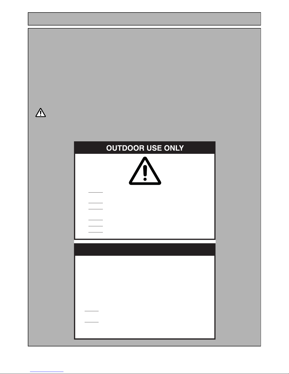
WARNING
OPERATE THIS APPLIANCE BEFORE READING THE
INSTRUCTION BOOKLET
PLACE ARTICLES ON OR AGAINST THIS APPLIANCE
STORE CHEMICALS OR FLAMMABLE MATERIALS, OR
SPRAY AEROSOLS NEAR THIS APPLIANCE
OPERATE THE APPLIANCE INDOORS
OPERATE IN AN ENCLOSED AREA
OPERATE THIS APPLIANCE BEFORE LEAK CHECKING
HOSES AND GAS CYLINDER CONNECTIONS
DO NOT
DO NOT
DO NOT
DO NOT
DO NOT
DO NOT
FOR YOUR SAFETY
1. SHUT OFF GAS TO THE APPLIANCE AND AT THE SOURCE IF POSSIBLE.
2. EXTINGUISH ANY OPEN FLAME.
3. OPEN THE HOOD.
4. PERFORM GAS LEAK TEST PROCEDURE.
5. IF '!3ODOUR CONTINUES, IMMEDIATELY CALL YOUR GAS SUPPLIER.
IF YOU SMELL GAS:
STORAGE:
1. DO NOT STORE OR USE PETROL OR OTHER FLAMMABLE VAPOURS
AND LIQUIDS IN THE VICINITY OF THIS OR ANY OTHER APPLIANCE.
2. DO NOT STORE GAS CYLINDERS THAT ARE NOT CONNECTED FOR
USE IN THE VICINITY OF THIS APPLIANCE.
3. ONLY TO BE USED OUTDOORS$/./453%).$//23.
Rinnai Australia - 2 - GT BBQ Range Owner’s Operation Manual
SAFETY INFORMATION
FAILURE TO COMPLY WITH THESE INSTRUCTIONS COULD RESULT IN A FIRE OR
EXPLOSION WHICH COULD CAUSE SERIOUS INJURY, DEATH OR PROPERTY
DAMAGE
BEFORE USING YOUR BARBECUE
• Check that the Barbecue supplied is correct for the gas type being used. The gas type Propane is
clearly labelled on the Barbecue.
• This Propane Barbecue MUST BE used with a gas cylinder or reticulated Propane supply.
LOCATION
• This Barbecue is for OUTDOOR use only. Refer to page 6 for details.
•DO
NOT operate the Barbecue indoors.
•DO
NOT operate in an enclosed area or use your Barbecue in garages, porches, breezeways, or sheds.
•DO
NOT operate in an unventilated area.
• This Barbecue must be placed on a level and stable surface. Surfaces which ignite easily (such as
carpet) MUST
NOT be used.
•DO
NOT obstruct the flow of air around the Barbecue whilst in use. Refer to the “Clearances and
Location” section page 6.
• Certain materials or items when placed near the Barbecue may be affected by the radiant heat and
could be damaged. Keep these items away from your Barbecue.
• Keep Barbecue away from combustible materials. Maintain Clearances as shown on page 6.
OPERATION
•DO
NOT connect the Barbecue directly to the gas cylinder or reticulated Propane supply without a
regulator.
• Propane Barbecues MUST
always use the hose and regulator supplied.
• Inspect the gas hose at least once per year, or whenever the gas cylinder is replaced. If the hose is
cracked, cut, abraded, discoloured or damaged in any other way the Barbecue must not be used. The
hose must be replaced if damaged or
when local regulations require this. Contact your Rinnai Service
agent/stockist or local regulating authority if uncertain. Replacement must only be carried out by an
authorised person.
• Avoid any twisting of the gas hose.
•DO
NOT alter or modify any parts of the Barbecue including any of the gas components.
• IF YOU SMELL
GAS?
1. Shut off gas to the Barbecue and at the source if possible.
2. Extinguish all flames.
3. Open hood.
4. Perform gas leak check procedure as per “Leak Testing” on page 4.
DO
NOT test for gas leaks with an open flame!
5. If the odour continues, immediately call your gas supplier.
•DO
NOT light the Barbecue with the hood or side burner lid closed.
•DO
NOT lean over the cooking surfaces whilst lighting the Barbecue.
•DO
NOT leave your Barbecue unattended while in use.
•DO
NOT use briquettes, wood, charcoal or other solid fuels in this Barbecue.
•DO
NOT use aluminium foil to line the burner box. Using foil in this manner can block off air for
combustion and ventilation and result in a dangerous condition.
•DO
NOT smoke whilst lighting your Barbecue.
• NEVER
use the two inner burners when cooking with the hood closed, use the outer burners only!
•DO
NOT heat unopened food containers as pressure build-up during heating may cause the container
to burst.
•DO
NOT move Barbecue whilst hot or in operation. Lock wheels during use.
IMPORTANT

Rinnai Australia - 3 - GT BBQ Range Owner’s Operation Manual
SAFETY INFORMATION
•DO NOT close the side burner lid whilst the side burner is alight.
•DO
NOT allow children or the infirm to operate or handle any parts of the Barbecue.
•DO
wear appropriate clothing whilst operating the Barbecue. Some synthetic fabrics (such as Nylon)
are highly flammable and should be avoided.
•DO
use good quality insulated oven mitts when operating the Barbecue.
• If the burners go out during operation, shut the gas supply off at the so urce and tur n all burner co ntrols
to ‘OFF’. Open the hood and wait at least 5 minutes before attempting to relight.
• Should a grease fire occur and if safe to do so, attempt to shut off the gas supply at the source, turn off
all burners and remove food if possible.
STORAGE
•DO
NOT store your gas cylinder indoors. Gas cylinders must be stored outdoors in a well ventilated
area out of reach of children and must not be stored in a building, garage or any other enclosed area.
• Barbecues using bottled gas: If stored indoors, ALWAYS
disconnect and remove the gas cylinder first.
Gas cylinders must be stored outdoors in a well ventilated area out of reach of children. They MUST
NOT be stored in a building, garage or any other enclosed area or in the vicinity of this or any other
appliance.
•DO
NOT store or use petrol or other flammable vapours and liquids in the vicinity of this or any other
appliance.
•DO
NOT store empty or full spare gas cylinders under or near this or any other appliance.
GAS CYLINDER PROPANE
• This Barbecue is designed for use with a 9kg LP Gas cylinder. This cylinder should conform to
AS 2030.1. DO
NOT connect this Barbecue to a gas cylinder of different capacity.
• The Barbecue is designed for use in the vapour withdrawal mode. Therefore it is important to always
store and use the gas cylinder in an upright position.
• For storage and when refilling / exchanging cylind ers , discon nect the hose an d regulat or at the cylinder
end only. Do not disconnect the hose and regulator from the Barbecue end.
• Gas cylinders should be inspected and tested periodically in accordance with local statutory
regulations. A dented or rusty gas cylinder may be hazardous and should not be used.
•DO
NOT subject the gas cylinder to excessive heat.
• Always close the cylinder valve when the Barbecue is not in use.
• The gas cylinder should be filled by a reputable gas dealer, or exchanged at a reputable gas cylinder
exchange outlet.
• Gas cylinders should be visually inspected and re-qualified as per local requirements.
Propane Gas
• The pressure regulator and hose assembly supplied with the appliance MUST be used.
• The pressure regulator supplied is fixed to have an outlet pressure of 2.75 kPa, any other pressure is
not suitable. The regulator and hose assembly are for bottled LP gas ONLY
.
• When the Barbecue is not in use, the hose and regulator must only be disconnected from the cylinder.
The hose and regulator must not be disconnected from the Barbecue unless it is being replaced. Such
replacement must only be carried out by an authorised person.
• Inspect the gas hose when replacing the gas cylinder, or once per year, whichever is more frequent. If
the hose is cracked, cut, abraded, discoloured or damaged in any other way, the Barbecue must not be
used. The hose must be replaced if damage d or when loca l regulation s require t his. Contact your Rinnai
Service Agent/Stockist or local regulating authority if unce rtain. Such replacement must only be carried
out by an authorised person.
HOSE AND REGULATOR
• Replacement pressure regulators and hose assemblies must be those specified by Rinnai for use with
this appliance.
• Avoid any twisting of the hose.
• Keep the gas hose away from hot surfaces or dripping grease or oil.

Rinnai Australia - 4 - GT BBQ Range Owner’s Operation Manual
SAFETY INFORMATION
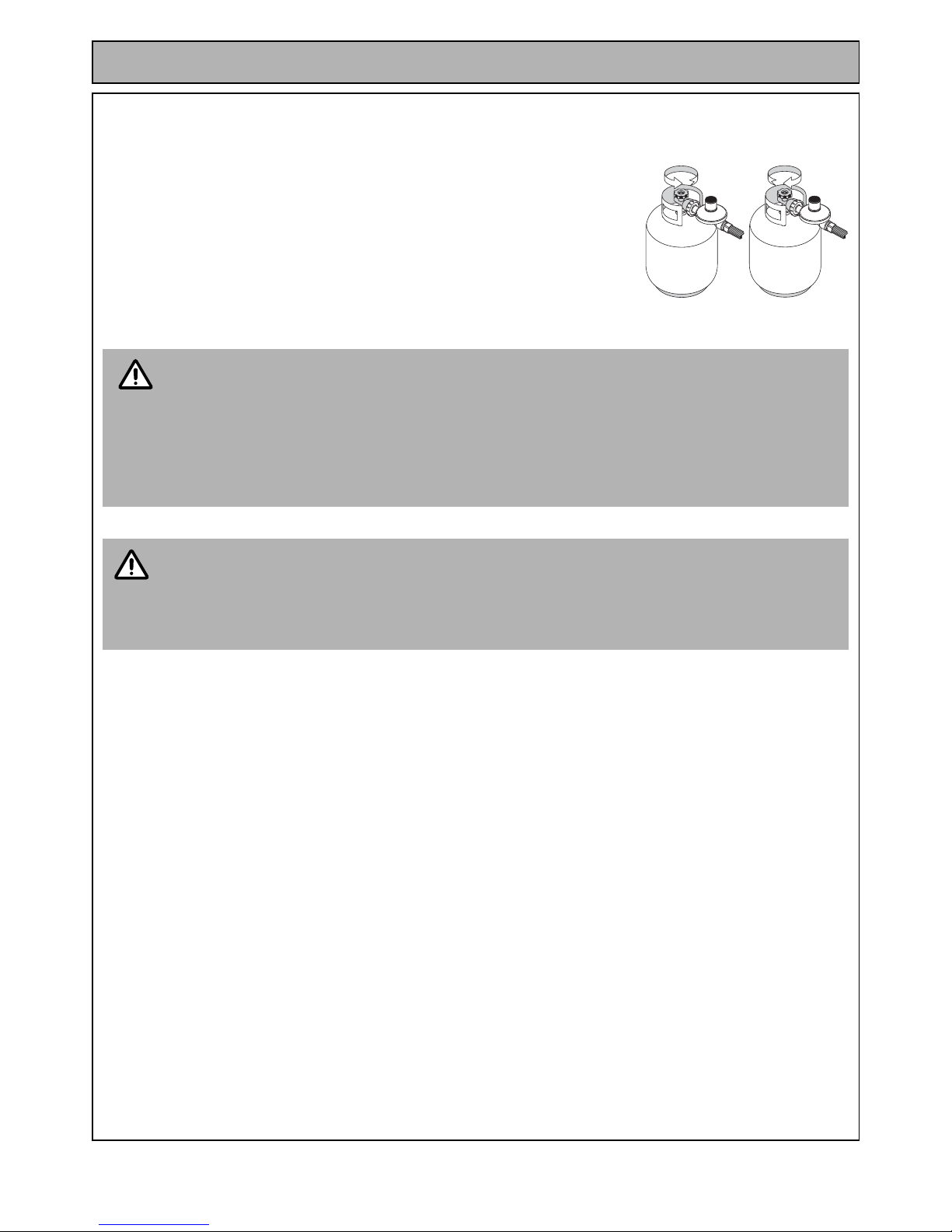
Gas Cylinder Installation
1. Familiarise yourself with the information in this manual, in particular the
items under "Safety Information" and "Gas Safety".
2. Ensure all burners are in the "OFF" position as shown.
3. Place the gas cylinder in the holder provided to secure the cylinder in
position.
4. Connect the regulator to the gas cylinder by turning the coupling nut
anticlockwise to tighten to a full s top, (left hand thread). The seal has now
engaged. An additional one half to three quarter turn is r equired to complete
the connection. Tighten by hand only. DO
NOT USE TOOLS.
The inlet connection is a POL or POLAUTO fitting which has a left
hand thread.
The user should regularly check the fitment and condition of the
rubber "O" ring seal located on the inlet connection nipple.
Leak Testing
DO
NOT test for gas leaks with an open flame!
5. Make a soapy solution by mixing one part liquid detergent (such as
dishwashing liquid and (4) four parts water.
6. Open the gas valve on the cylinder by turning it anticlockwise.
7. Apply the soapy solution to all visible gas connections in the vicinity of the
cylinder and regulator and where the gas hoses attach to the fitting on the
solid Barbecue’s gas pipe and to the side shelf burner (if fitted). Gas leaks
will show as small bubbles in the soapy solution.
8. If there is a gas leak from the connection between the regulator and gas
cylinder, close the gas valve on the cylinder by turning it clockwise.
Disconnect the regulator and hose assembly from the cylinder by turning
the coupling nut clockwise to disengage. Inspect for debris inside the
cylinder fitting and fitting at the end of the regulator. Remove debris and
reconnect as per step 4 above. Retest for gas leaks.
If there are still gas leaks from the connection between the
regulator and gas cylinder or any other connec tions contact your
Rinnai Service Agent/Stockist for assistance. Leaking
connections other than the connection between the regulator
and gas cylinder must only be repaired by an authorised person.
If gas leaks are present DO
NOT operate the Barbecue.
OFF
POSITION
NOTE
WARNING
CAUTION
Gas leaks will
show as small
bubbles in the
soapy solution
Rinnai Australia - 5 - GT BBQ Range Owner’s Operation Manual
Gas Cylinder Removal - Propane.
1. Ensure that the gas cylinder valve is “OFF” befo re att emp ting to disc onne ct
gas cylinder from Barbecue. To remove the gas cylinder from the hose and
regulator follow the reverse order of the gas cylinder installation on page 4
procedure.
Also check for leaks when:
• Prior to first use
• At the beginning of each new season
• Every time the cylinder has been changed
• After maintenance has been carried out
• After prolonged storage period
DANGER - IF YOU SMELL OR HEAR THE HISS OF ESCAPING GAS FROM THE GAS CYLINDER
• KEEP CLEAR OF THE GAS CYLINDER
• TURN ALL CONTROLS ON THE BARBECUE TO “OFF”
• EXTINGUISH ANY FLAME
• REMOVE LID OR OPEN HOOD
• IF GAS ODOUR CONTINUES, IMMEDIATELY CALL YOUR GAS SUPPLIER OR FIRE
DEPARTMENT
• Before initial use, and periodically thereafter, we suggest you wash your Barbecue using a
mild soap and warm water solution. You can use a wash cloth or sponge for this process.
• DO NOT use a stiff wire brush or similar. These will scratch stainless steel and chip painted/
coated surfaces (varies by model) during the cleaning process.
• DO NOT use oven cleaners, or similar compounds as these may damage coated surfaces.
ON
OFF
WARNING
HINT
SAFETY INFORMATION
Rinnai Australia - 6 - GT BBQ Range Owner’s Operation Manual
CLEARANCES AND LOCATION
Clearances
The following minimum clearances must be maintained:
• Top 1000 mm - measured from the top of the cooking surface.
• Rear 450 mm - measured from the rear main panel.
• Sides 250 mm - measured from the oute r mo st edg e of the ba rb e cu e.
Openings around the perimeter of the appliance provide air for coolin g and combustion and must not be obstructed.
Location
This appliance shall only be used in an above ground open-air situation with natural ventilation, without stagnant
areas, where gas leakage and products of combustion are rapidly dispersed by wind and natural convection.
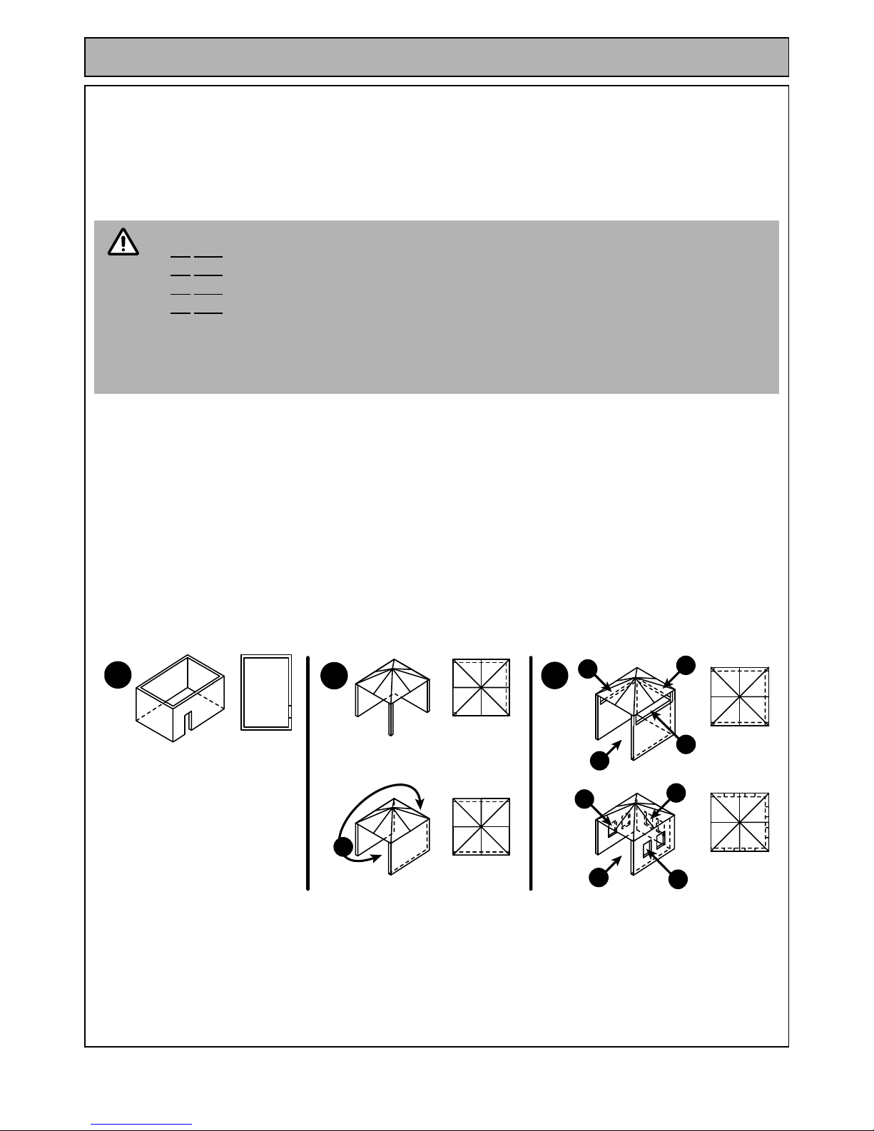
Any enclosure in which the appliance is used shall comply with one of the following (
see drawings below
):
1. An enclosure with walls on all sides, but at least one permanent opening at ground level and no overhead cover.
2. Within a partial enclosure that includes an overhead cover and no more than two walls.
A. both ends open.
3. Within a partial enclosure that includes an overhead cover and more than two walls, the following shall apply-
B. at least 25% of the total wall area is completely open; and
C. at least 30% of the remaining wall area is open and unrestricted.
In the case of balconies, at least 20% of the total of the side, back and front wall areas shall be and remain open
and unrestricted.
.
Vehicles and Boats
The barbecue is not intended to be installed in or used on recreational vehicles and/or boats.
• This barbecue is for OUTDOOR use only.
•DO
NOT operate the barbecue indoor s.
•DO
NOT operate in an enclosed area.
•DO
NOT operate in an unventilated area.
•DO
NOT obstruct the flow of air around the barbecue whilst in use.
• This barbecue must be placed on a level and stable surface.
• Certain materials or items when placed near the barbecue may be affected by the radiant heat
and could be damaged. Keep these items away from your barbecue.
• Keep barbecue away from combustible materials.
CAUTION
Plan View
Plan View
Plan View
Plan View
Plan View
1
2
A
3
B
B
C
C
C
C
C
C
Rinnai Australia - 7 - GT Range BBQ Owner’s Operation Manual
ASSEMBLY
TOOLS REQUIRED
A Phillip's screw driver and a spanner (spanner supplied with GT114PHB / GT114PHS and GT104BHB /
GT104BHS models) are required for the assembly of your Rinnai Barbecue.
UNPACKING AND ASSEMBLY TIPS
1. Carefully remove packaging taking care not to damage any components.
BARBECUE ASSEMBLY MODELS GT114PHB / GT114PHS
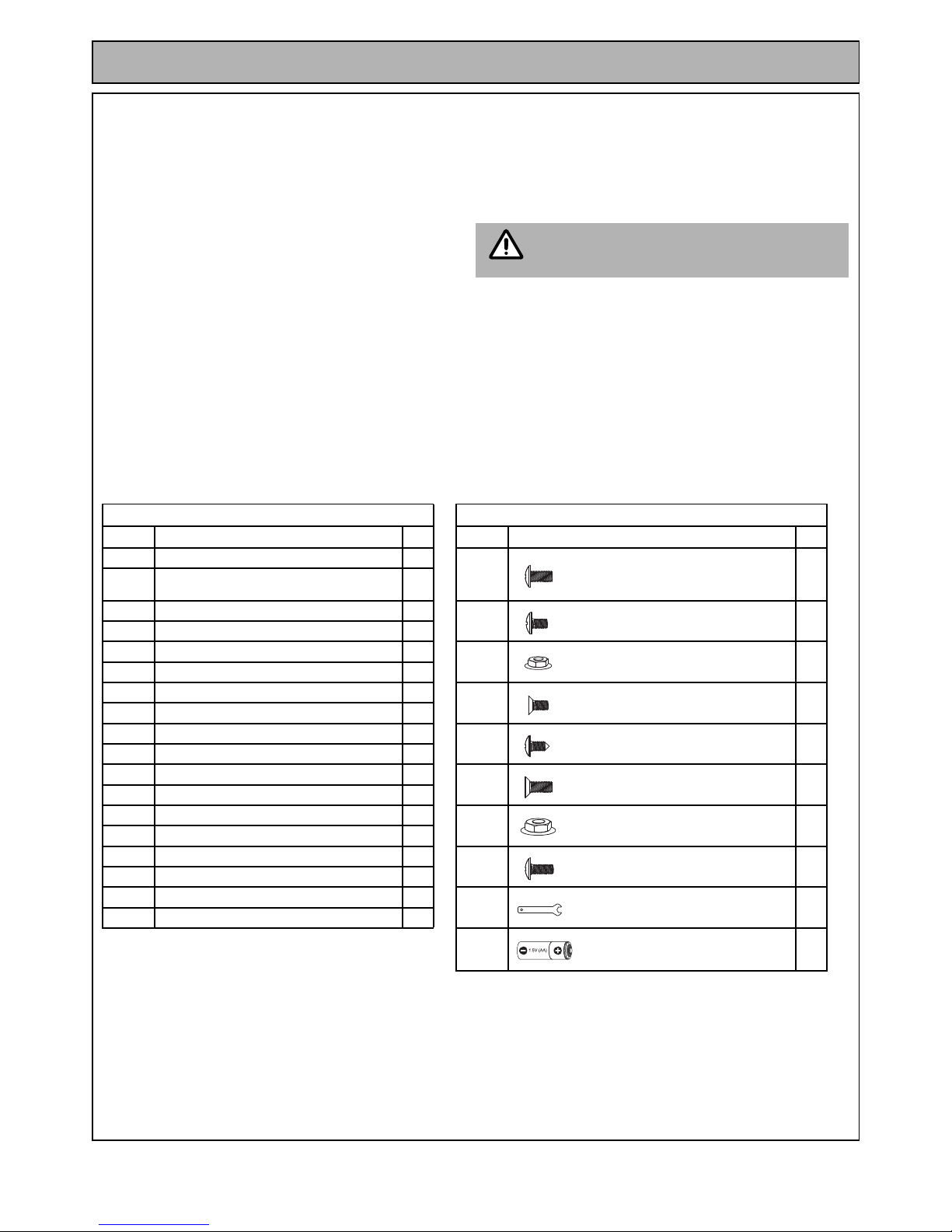
List of Assembly Components and Hardware
For full Hardware Pack refer to Hardware Pack Table page 45.
2. Flatten the cardboard packaging and use this as a
protective work surface to assemble on.
Find a suitable flat surface for the
assembly of the Barbecue components.
3. Some protective coatings may need to be removed prior to assembly, in particular the white PVC film on
stainless steel sheet metal.
4. In some instances DO NOT tighten all screws and nuts until the trolley is assembled.
5. Pre-screwing of connection points for securing the side shelves will assist in securing shelves smoothly.
6. The packaging should contain all items as listed. If any items are missing or damaged, DO NOT continue with
assembly and contact your supplier.
7. When assembly is complete recycle and discard packaging as appropriate.
ASSEMBLY COMPONENTS HARDWARE
Part No. Description Qty Part No. Description Qty
A. Barbecue Head 1
a. Phillips Head Screw 1/4"x1/2" 12
8. Door Stop Plate-Upper 1
8a. Door Stop Plate Lower 1
b. Phillips Head Screw 3/16"x3/8" 12
10. Trolley Panel-Right 1
30. Grease Tray Bracket 1
c. Flange Nut 3/16" 8
31. Grease Tray 1
34. Separation Panel Bracket 2
d. Countersunk Flat Head Screw 3/16"x3/8" 2
39. Side Shelf-Left 1
43. Trolley Door-Left 1
e. Phillips Head Screw M5x10MM 2
44. Trolley Door-Right 1
43. Trolley Door-Left 1
f. Countersunk Flat Head Screw 1/4"x1/2" 4
44. Trolley Door-Right 1
48. Side Burner-Right 1
g. Flange Nut 1/4" 4
56. Separation Panel 1
57. Trolley Panel-Left 1
h Phillips Head Screw 3/16"x1/2" 4
61. Castors 4
63. Trolley Bottom Panel 1
i. Spanner 1
64. Trolley Panel-Rear 1
j. Battery 1
NOTE

Rinnai Australia - 8 - GT Range BBQ Owner’s Operation Manual
ASSEMBLY
Assembly Method
Step 1. Install Trolley Panels (10 / 57) onto Trolley Bottom Panel (63) with Screws (a. x4).
Step 2. Install the castors (61) onto the bottom of the Trolley Bottom Panel (63) using spanner (f. provided).
Step 3. Install Trolley Rear Panel (64) onto Trolley Panels (10 / 57) with Screws (b. x4) and Flange Nuts (c. x4).
57.
10
63
a. (x4)
(GT114PHB - Black)
(GT114PHS - Stainless Steel)
i.
61
64
b. (x4)
c. (x4)
b
c
(GT114PHB - Black)
(GT114PHS - Stainless Steel)
(GT114PHB - Black)
(GT114PHS - Stainless Steel)
This hole
not in use
Rinnai Australia - 9 - GT Range BBQ Owner’s Operation Manual
ASSEMBLY
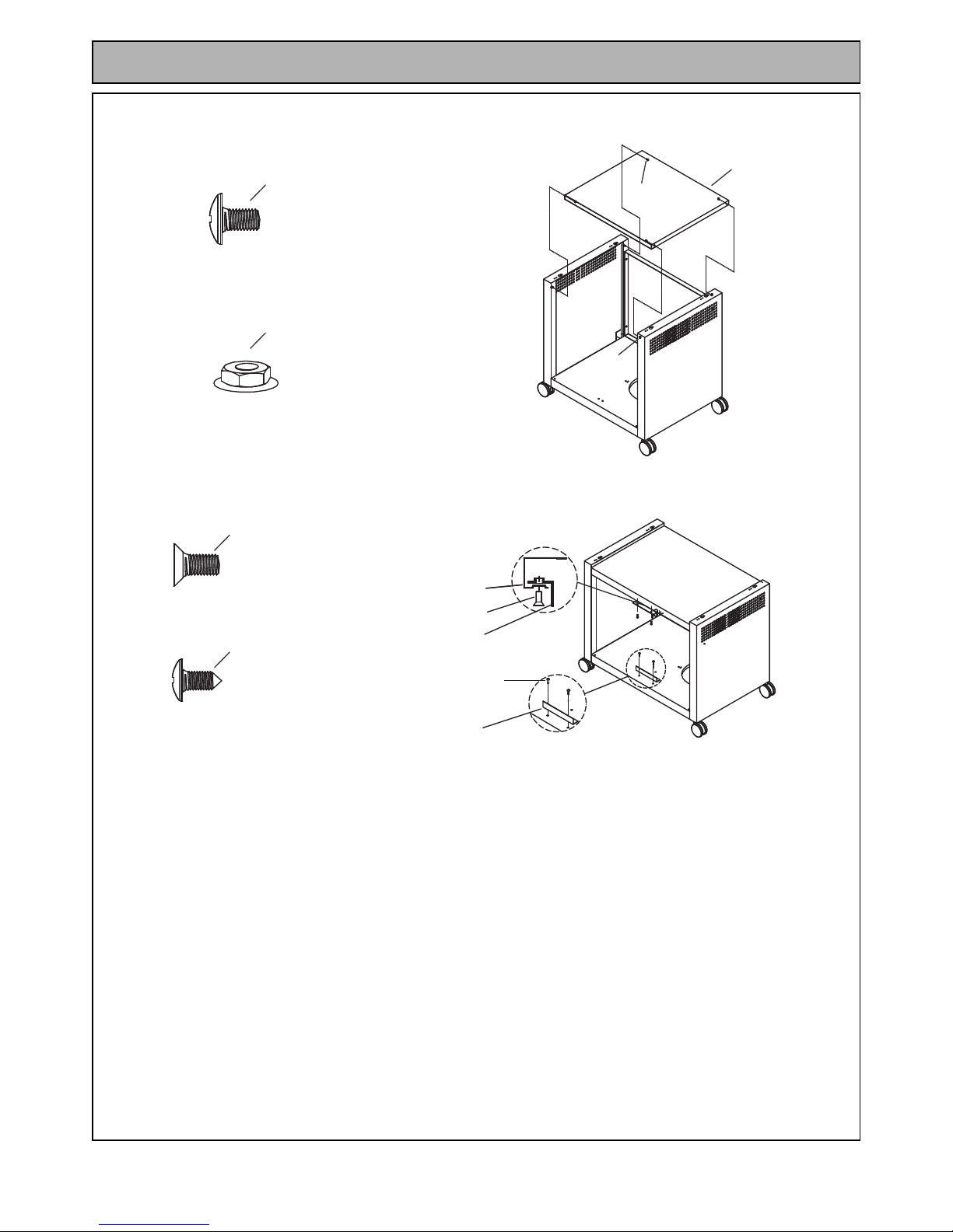
Step 4. Install Trolley Separation Panel (56) onto the Trolley Panels (10 / 57) with Screws (b. x4) and Flange
Nuts (c. x4).
Step 5. Install Upper Door Stop Plate (8) onto the Trolley Separation Panel (56) with Screws (d. x2).
Install Lower Door Stop Plate (8a) onto the Trolley Bottom Panel (63) with Screws (e. x2).
56
b. (x4)
c. (x4)
b
c
(GT114PHB - Black)
(GT114PHS - Stainless Steel)
(GT114PHB - Black)
(GT114PHS - Stainless Steel)
d. (x2)
e. (x2)
8
56
8a
d
e
(GT114PHB - Black)
(GT114PHS - Stainless Steel)
(GT114PHB - Black)
(GT114PHS - Stainless Steel)
Rinnai Australia - 10 - GT Range BBQ Owner’s Operation Manual
ASSEMBLY
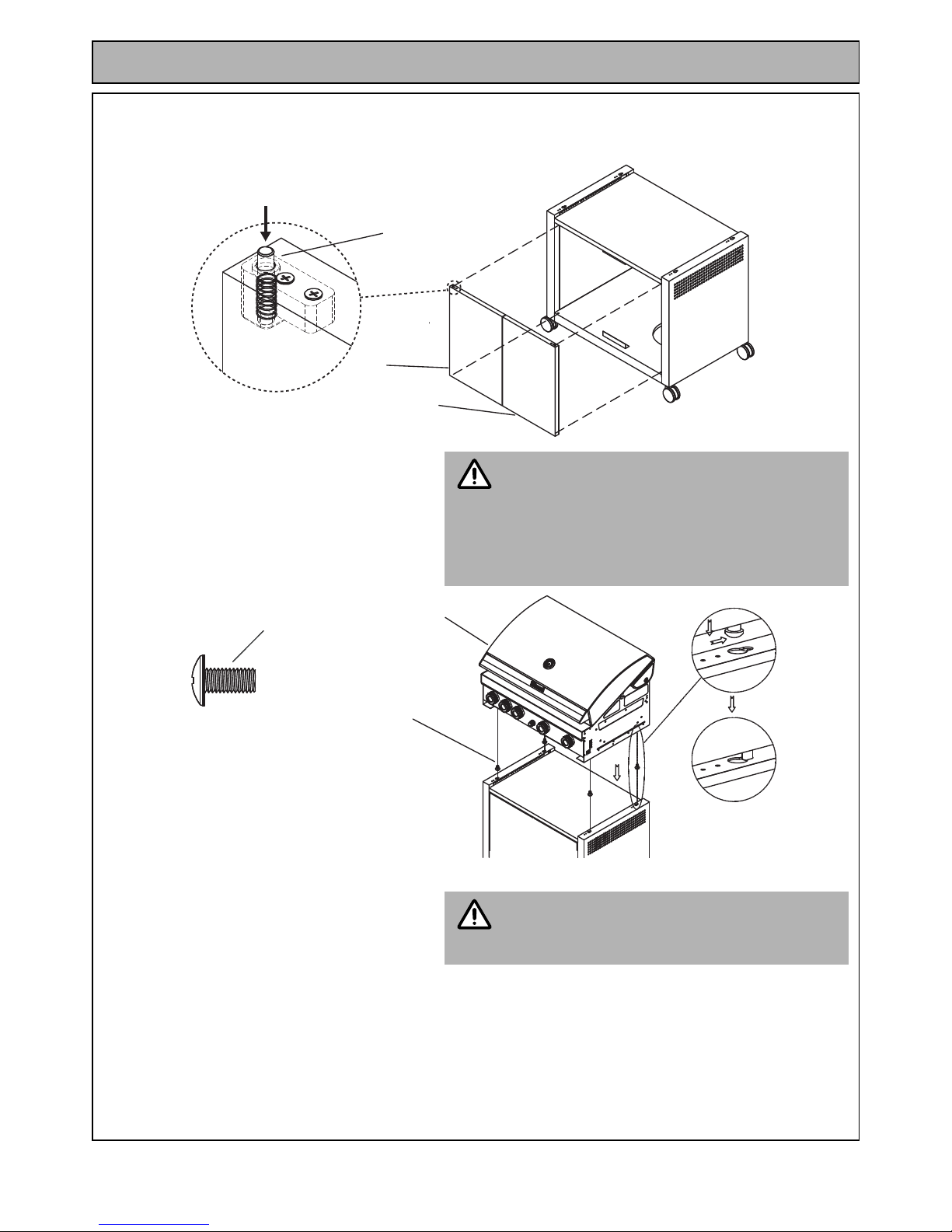
Step 6. Install the Trolley Doors (43 / 44) by first locating the lower door hinge pin into the Trolley Bottom Panel
(63). Then depress the spring loaded upper hinge pin and locate it into the bottom of the Trolley
Separation Panel (56).
Step 7. Partially install Screws (a. x4) into the
underside of the Barbecue Head (A).
Locate the screw heads into the
keyholes of the Trolley Panels (10 / 57)
and then slide fully back to lock into
position as shown in Fig. 1, then tighten
all screws.
Barbecue Head installation requires two
persons. Ensure to remove all the un-installed
components, accessories and burner plates
from the Barbecue Head before attempting
installation.
DO NOT TIGHTEN ANY SCREWS UNTIL THE
BARBECUE HEAD IS IN THE FINAL POSITION.
Step 8. From inside the trolley assembly attach
a Separation Panel Bracket (34) onto
each end of the Separation Panel (34)
with screws (b. x4).
The Separation Panel Brackets MUST BE
installed as they are necessary to enable the
isolation of the cabinet area from the Barbe cue
Head.
Upper Hinge Pin
43
44
Depress
IMPORTANT
A
a
a. (x4)
Fig.1
(GT114PHB - Black)
(GT114PHS - Stainless Steel)
IMPORTANT

Rinnai Australia - 11 - GT Range BBQ Owner’s Operation Manual
ASSEMBLY
Step 9. The Side Burner (48) is to be installed on
the right hand side of the Barbecue Head
(A).
DO NOT TIGHTEN ANY SCREWS UNTIL ALL
PARTS AND FITTINGS FOR THE SIDE BURNER
ARE IN FINAL POSITIONS.
Partially install Screws (h. x2) into the right hand side of the Barbecue Head (A).
Locate the keyholes of the Side Burner (48) over the right han d set of screws ( h.) and slide fully do wn to
lock into position. Partially install the Screws (a. x2).
Insert Screws (f. x2) from the inside of the burner box through both the side of the Barbecue He ad (A)
and the Side Burner (48), then attach and tighten Flange Nuts (g. x2). Tighten Screws (f. x2 and a. x2).
The Side Shelf (39) is to be installed on
the left hand side of the Barbecue Head
(A).
DO NOT TIGHTEN ANY SCREWS UNTIL ALL
PARTS AND FITTINGS FOR THE SIDE SHELF
ARE IN FINAL POSITIONS.
Partially install Screws (h. x2) into the left hand side of the Barbecue Head (A).
Locate the keyholes of the Side Shelf (39) over the left hand set of screws (h.) and slide fully down to
lock into position. Partially install the Screws (a. x2).
Insert Screws (f. x2) from the inside of the burner box through both the side of the Barbecue He ad (A)
and the Side Shelf (39), then attach and tighten Flange Nuts (h. x2). Tighten Screws (h. x2 and a. x2).
34
b. (x4)
b.
34
56
(GT114PHB - Black)
(GT114PHS - Stainless Steel)
IMPORTANT
IMPORTANT
a. (x4)
39
48
a.
a.
a.
a.
f.
h. (x4)f. (x4)
g. (x4)
f.
g.
g.
h.
h.
h.
h.
A
(GT114PHB - Stainless Steel)
(GT114PHS - Stainless Steel)
(GT114PHB - Stainless Steel)
(GT114PHS - Stainless Steel)
(GT114PHB - Stainless Steel)
(GT114PHS - Stainless Steel)
(GT114PHB - Stainless Steel)
(GT114PHS - Stainless Steel)
Rinnai Australia - 12 - GT Range BBQ Owner’s Operation Manual
ASSEMBLY
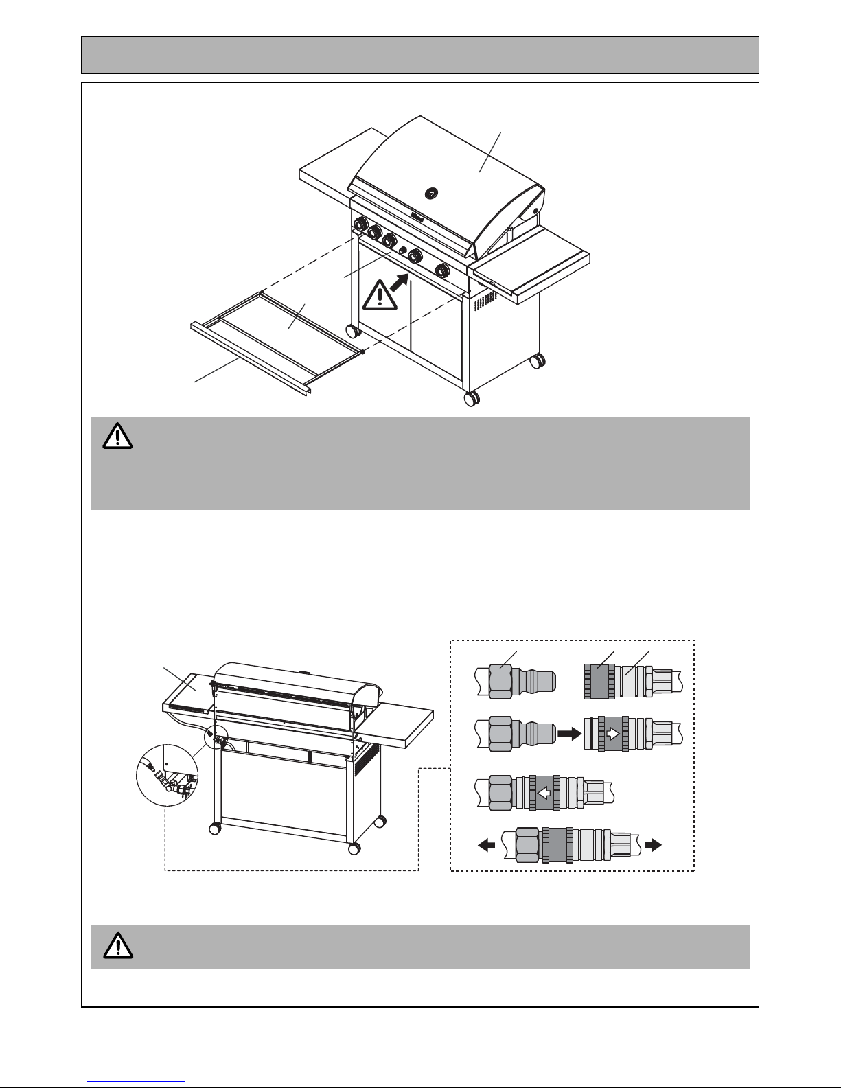
Step 10. Insert the Grease Tray (30 / 31) into the gap at the base of the Barbecue Head (A).
Step 11. Connect the gas train to the Side Burner (48) with the quick connect (Fig. 1) as follows:
If the top of the doors do not line up, a correction can be made by adjusting the height of the
castors. Slightly unscrew one of the front castors and note the movement in the top of the doors.
If the alignment becomes worse, screw back the caster and adjust the cast or on the other side. The
diagonally opposite castors may also be used if extra adjustment is required.
Re-adjustment may also be required if the barbecue is later shifted to a different location.
1. Align the Plug (I) with the Socket (II).
2. Slide spring loaded Locking Sleeve (III) back and insert the plug (I) into the socket (II) until it is fully home.
3. Allow the Locking Sleeve (III) to slide forward into place.
4. Test the mechanical connection by pulling on the Socket (I) to confirm that it has been locked into place.
Before attempting to use the Barbecue or side burner, ensure to leak test the quick connect
connection in accordance with “Leak Testing” on page 4.
30
31
A
56
NOTE
I IIIII
2.
4.
3.
1.
48
Fig. 1
IMPORTANT
Rinnai Australia - 13 - GT Range BBQ Owner’s Operation Manual
ASSEMBLY
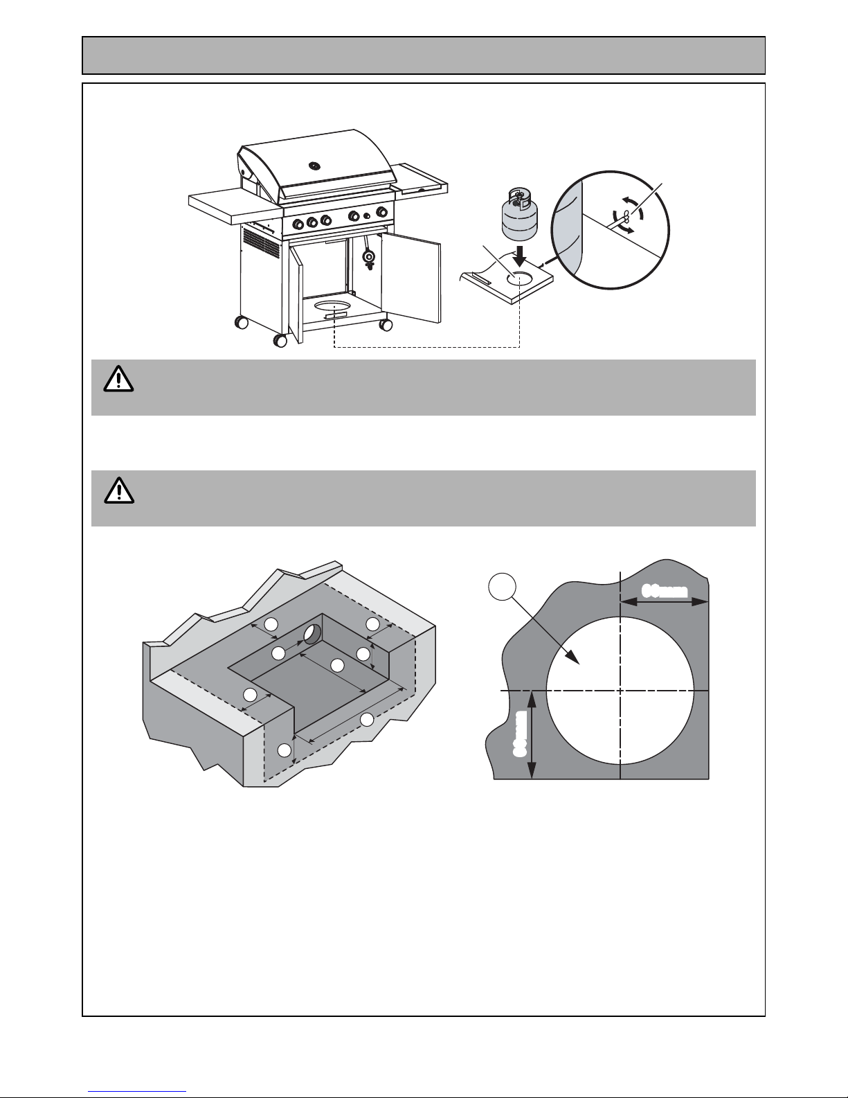
Step 12. Insert the Gas Cylinder into hole provided in the trolley cabinet (I), then secure the cylinder in place with
Wing Nut Clamp (II).
BARBECUE ASSEMBLY / INSTALLATION MODELS GT104BHB / GT104BHS
Building of non combustible structure / opening
Connect the Gas Cylinder in accordance with “Gas Cylinder Installation” on page 4.
Before attempting to use the barbecue or side burner, ensure to leak test the connections in
accordance with “Leak Testing” on page 4.
This Barbecue is suitable for installation into ‘non combustible’ (masonry) structures only. This
Barbecue must not be installed into combusti ble structures, such as structures made from wood,
plasterboard, particle board etc. Structure must be constructed in a ccordance with AS/NZS 560 1.
Opening Dimensions
A. 225mm Minimum
B. 590mm Minimum
C. 830mm - 840mm
D. 450mm Minimum to combustible and 150mm to non-combustible clearance.
E. 250mm Minimum non-combustible clearance.
F. 100mm Minimum Diameter.
I
II
NOTE
IMPORTANT
B
A
D
E
E
E
C
F
F
60mm
60mm
60mm
60mm
Rinnai Australia - 14 - GT Range BBQ Owner’s Operation Manual
ASSEMBLY
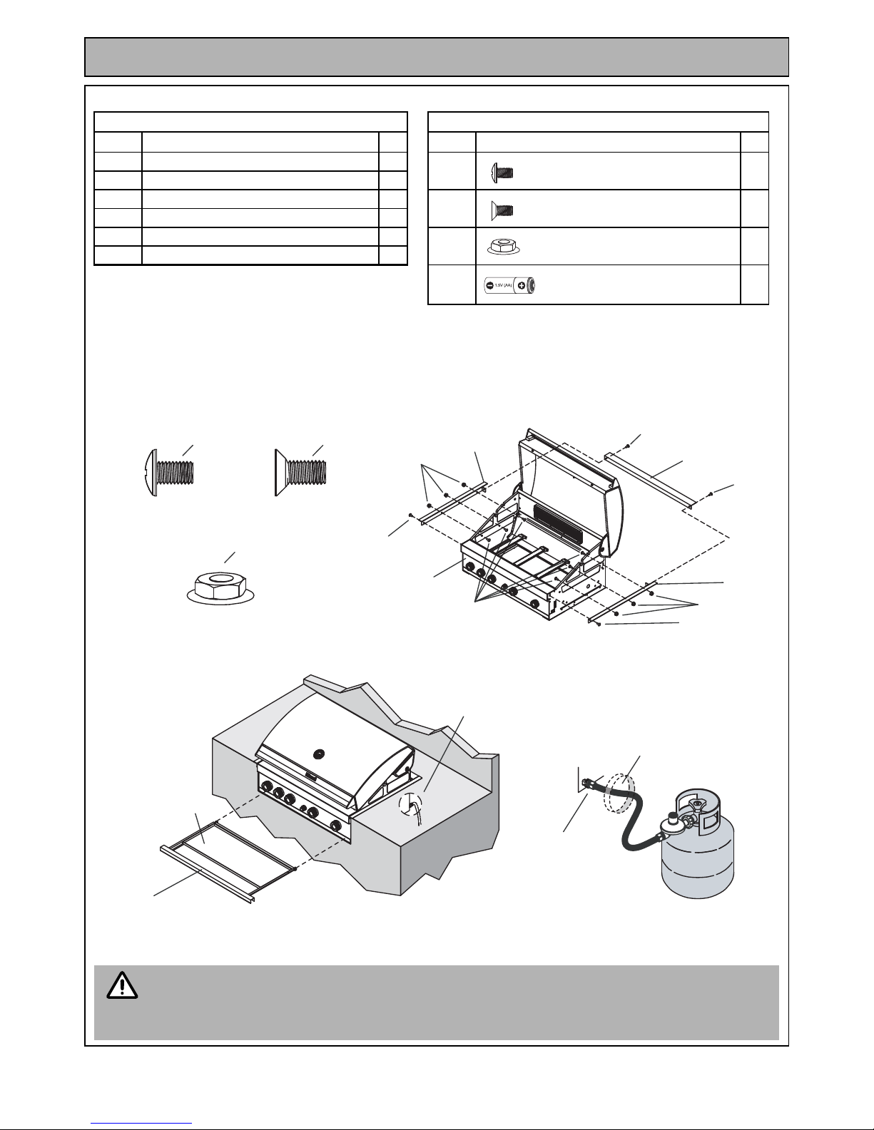
List of Assembly Components and Hardware - GT104BHB / GT104BHS
Assembly Method
Step 1. Install the Trim Bracket-Left (37) with Screw (a. x1), Insert Screws (b. x3) from the inside of the burner
box through both the side of the Barbecue Head (A) and the Trim Bracket, then attach and tighten
Flange Nuts (c. x3). Repeat the procedure for Trim Bracket-Right (38). Install the Trim Bracket-Rear
(39) with Screws (a. x2).
Step 2). Insert the Grease Tray (30 / 31) into the gap at the base of the Barbecue Head (A).
ASSEMBLY COMPONENTS HARDWARE
Part No. Description Qty Part No. Description Qty
A. Barbecue Head 1
a. Phillips Head Screw 1/4"x3/8" 4
30. Grease Tray Bracket 1
31. Grease Tray 1
b. Countersunk Flat Head Screw 1/4"x3/8" 6
37. Trim Bracket-Left 1
38. Trim Bracket-Right 1
c. Flange Nut 1/4" 6
39. Trim Bracket-Rear 1
d. Battery 1
For full Hardware Pack refer to Hardware Pack Table page 49.
• Connect the Gas Cylinder in accordance with “Gas Cylinder Installation” on page 4.
• Before attempting to use the Barbecue, ensure to leak test the connections in accordance with
“Leak Testing” on page 4.
• When gas cylinders are located in an enclosed space ventilation must comply with AS 4557.
a. (x4)
b. (x4)
c. (x4)
39
38
37
a.
a.
a.
a.
c.
c.
b.
A
(GT104BHB - Stainless Steel)
(GT104BHS - Stainless Steel)
(GT104BHB - Stainless Steel)
(GT104BHS - Stainless Steel)
(GT104BHB - Stainless Steel)
(GT104BHS - Stainless Steel)
Gas Line
31
Gas Line
30
Hole to allow regulator
access to gas cylinder
will need to be 100mm
or greater!
NOTE
Rinnai Australia - 15 - GT Range BBQ Owner’s Operation Manual
ASSEMBLY
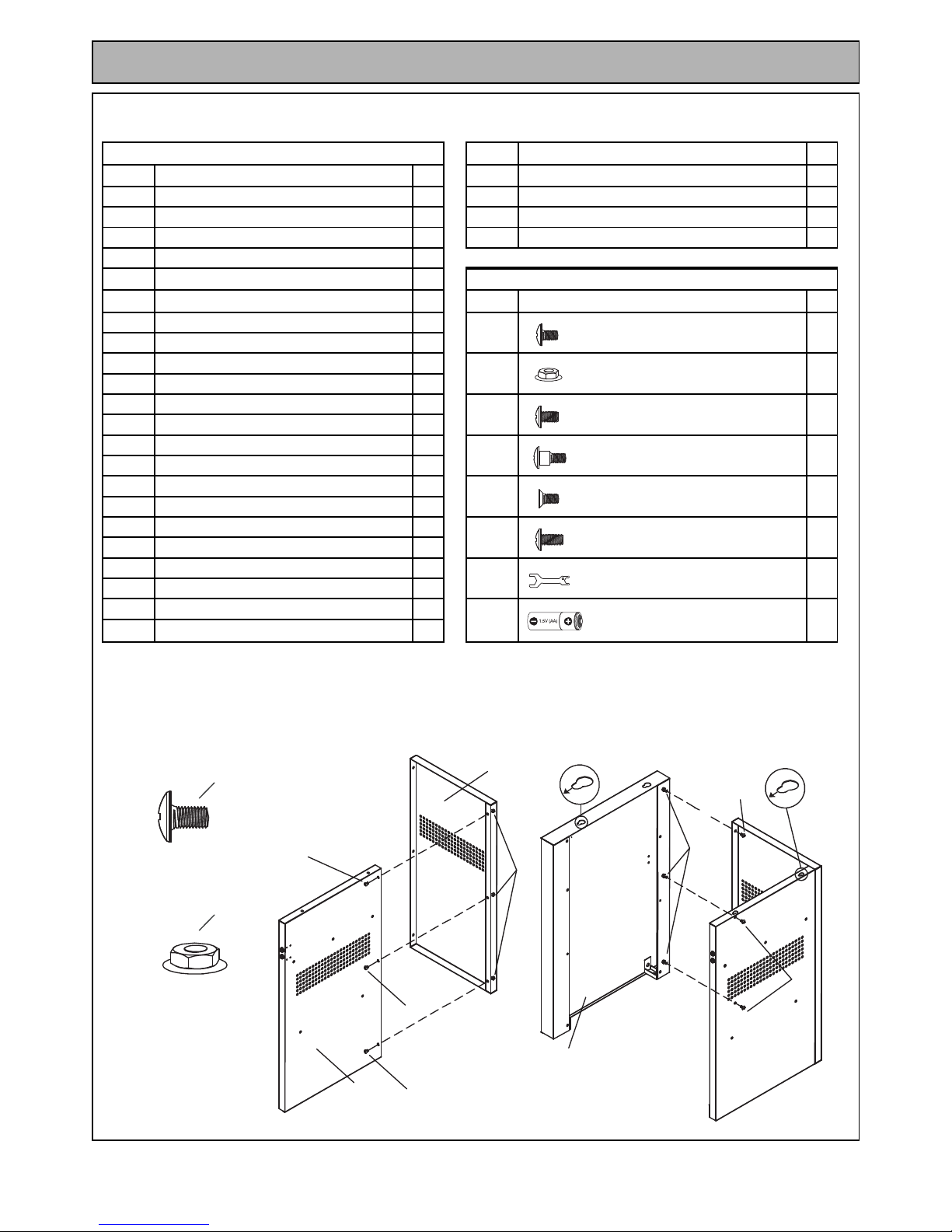
BARBECUE ASSEMBLY MODELS GT114PIHB / GT114PIHS
List of Assembly Components and Hardware
Assembly Method
Step 1. Install Left Cabinet-Rear Panel (56) onto Left Cabinet-Right Panel (64) with Screws (a. x3) and Flange
Nuts (b. x3). Install Left Cabinet-Left Panel (54) onto Left Cabinet-Rear Panel (56) with Screws (a. x3)
and Flange Nuts (b. x3).
ASSEMBLY COMPONENTS
65. Partition Panel 1
Part No. Description Qty
66. Bowl Support Bracket-Right 1
A. Barbecue Head 1 67. Right Cabinet-Left Panel 1
B. Side Burner Assembly 1 70. Separation Panel 1
8. Separation panel Bracket-Left 1 71. Support Bracket 1
10. Separation panel Bracket-Right 1
11. Right Cabinet-Rear Panel 1
HARDWARE
17. Right Cabinet-Bottom Panel 1
Part No. Description Qty
18. Right Cabinet-Right Panel 1
a. Phillips Head Screw 3/16"x3/8" 20
27. Door Cabinet-Left 1
30. Grease Tray Bracket 1
b. Flange Nut 3/16" 24
31. Grease Tray 1
33. Right Cabinet-Front Bracket 1
c. Phillips Head Screw 1/4"x3/8" 22
53. Side Shelf-Left 1
54. Left Cabinet-Left Panel 1
d. Bolt 3/16"x 9/16" 4
55. Left Cabinet-Storage Shelf 1
56. Left Cabinet-Rear Panel 1
e. Countersunk Flat Head Screw 1/2”x 3/8" 20
57. Level Adjuster 8
58. Left Cabinet-Front Bracket 1
f. Phillips Head Screw 1/4"x1/2" 12
59. Door Hinge Bracket 2
60. Door Cabinet-Left 1
g. Spanner 1
62. Left Cabinet-Bottom Panel 1
63. Bowl Support Bracket-Left 1
h. Battery 1
64. Left Cabinet-Right Panel 1
For full Hardware Pack refer to Hardware Pack Table page 54
56
54
64
FRONT/TOP
FRONT/TOP
a.
a.
a.
b.
b.
a.
a.
a. (x4)
b. (x4)
(GT114PIHB - Black)
(GT114PIHS - Stainless Steel)
(GT114PIHB - Black)
(GT114PIHS - Stainless Steel)
 Loading...