

Page 1
HOME OWNER / INSTALLER
FOR YOUR SAFETY
THIS MANUAL MUST BE READ IN ITS
ENTIRETY BEFORE OPERATING HEATER
FS35ETRBN/US FS35ETRSN/US
FS35ETRBL/US FS35ETRSL/US
Gas Radiant Sp ace Heater
Owners Operation and Installation Manual
WARNING: If the information in these instructions are not
followed exactly, a fire or explosion may result causing
property damage, personal injury or loss of life.
Do not store or use gasoline or other flammable vapors
and liquids in the vicinity of this or any other appliance.
WHA T T O DO IF YOU SMELL GAS
• Do not try to light any appliance.
• Do not touch any electrical switch; do not use any phone in
your building.
• Immediately call your gas supplier from a neighbor’s phone.
Follow the gas supplier’s instructions.
• If you cannot reach your gas supplier, call the fire department.
Installation and service must be performed by a qualified
installer , service agency or the gas supplier .
zx
This heater has been designed to code ANSI Z 21.88a-2000
effective 7-1-2002
This appliance is only for use with the type of gas indicated on
the rating plate.
This appliance is not convertible for use with other gases.
INSTALLER: MUST LEAVE THIS MANUAL WITH THE UNIT AFTER INSTALLATION
OWNER: RETAIN THIS MANUAL SAFELY, FOR FUTURE REFERENCE
Page 2

LIMITED WARRANTY
RINNAI FIREPLACE HEATER
WHAT IS COVERED?
This Warranty covers any defects in materials or workmanship, subject to the terms stated below. This
Warranty extends to the original purchaser and subsequent transferees, but only while the product remains at
the site of the original installation. This Warranty only extends through the first installation of the product and
terminates if the product is moved or reinstalled at a new location.
HOW LONG DOES COVERAGE LAST?
Item Period of Coverage
All Parts and Components 2 Years from Date of Purchase
WHAT WILL RINNAI DO?
Rinnai will repair or replace the product or any part or component that is defective in materials or workmanship,
except as set forth as follows. Rinnai will pay reasonable shipping costs, provided you obtain prior authorization
from an Authorized Rinnai Distributor. Rinnai will not pay labor charges associated with the repair or replacement
of the product or any part or component. All repair parts must be genuine Rinnai parts. All repairs or replacements
must be performed by an individual or servicing company that has been authorized by Rinnai or its distributor.
Replacement of the product or replacement of the heat exchanger may be authorized by Rinnai only. Rinnai
does not authorize any person or company to assume for it any obligation or liability in connection with the
replacement of a product or heat exchanger. If Rinnai determines that repair of a product is not possible,
Rinnai will replace the product with a comparable product, at Rinnai’s discretion.
HOW DO I GET SERVICE?
You must contact an Authorized Distributor or Installer for the repair of a defective product under this Warranty.
Failure to contact an Authorized Distributor or Installer will void the Warranty. For the name of the Authorized
Distributor or Installer nearest you, please contact your local HVAC dealer or gas service technician, visit the
Rinnai website (www.rinnai.us), call Rinnai at 1-800-621-9419 or write to Rinnai, 103 International Drive, Peachtree
City, Georgia 30269.
Proof of purchase is required. You can show proof of purchase with a dated sales receipt, or by completing
and mailing the enclosed Warranty registration card within 30 days of purchasing the product. Please complete
the enclosed Warranty registration card and mail it to Rinnai at the address shown on the card. Receipt of this
card by Rinnai will constitute proof-of-purchase for this product. However, return of this Warranty registration
card is not necessary in order to validate this Warranty.
WHAT IS NOT COVERED?
This Warranty does not cover any failures or operating difficulties due to accident, abuse, misuse, alteration,
misapplication, force majeure, improper installation, improper maintenance or service, or for any other causes
other than defects in materials or workmanship. This warranty does not apply to any product whose serial
number or manufacture date has been defaced.
Rinnai is not liable for any special, incidental, indirect or consequential damages that may arise, including
damage to person or property, loss of use, or inconvenience. Some states do not allow the exclusion or
limitation of incidental or consequential damages, so the above limitation may not apply to you.
LIMITATION ON IMPLIED WARRANTIES
Any implied warranties of merchantability and fitness arising under state law are limited in duration to the
period of coverage provided by this limited Warranty, unless the period provided by state law is less. Some
states do not allow limitations on how long an implied Warranty lasts, so the above limitation may not apply
to you.
This Warranty gives you specific legal rights, and you may also have other rights which vary from state to
state.
2
Page 3
WARNING
IMPROPER INSTALLATION, ADJUSTMENT, ALTERATION, SERVICE OR
MAINTENANCE CAN CAUSE PROPERTY DAMAGE, PERSONAL INJURY OR
LOSS OF LIFE.
INSTALLATION AND SERVICE MUST BE PERFORMED BY A QUALIFIED
INSTALLER, SERVICE AGENCY OR THE GAS SUPPLIER.
This manual applies to the following models only:
FS35ETRBN/US FS35ETRSN/US
FS35ETRBL/US FS35ETRSL/US
Freestanding Fire ETR
Electronic Timer Remote
Table of Contents
Limited warranty ............................................................................................................ 2
Contacts ........................................................................................................................ 3
Specifications ................................................................................................................ 4
Dimensions ................................................................................................................... 4
Important points / usage and installation musts ............................................................... 5
Technical specifications ................................................................................................. 7
For your Safety .............................................................................................................. 8
Control panel layout........................................................................................................ 9
Operation....................................................................................................................... 9
Location......................................................................................................................... 13
Venting .......................................................................................................................... 14
Gas connection .............................................................................................................. 14
Log installation ...............................................................................................................15
Testing and commissioning ............................................................................................ 16
Maintenance instructions ................................................................................................ 17
PCB layout..................................................................................................................... 19
Wiring diagram .............................................................................................................. 19
Wiring diagram-ladder ................................................................................................... 20
Trouble shooting ............................................................................................................ 20
Error codes .................................................................................................................... 21
Exploded diagrams........................................................................................................ 22
Spare parts list ............................................................................................................... 24
Installation notes ............................................................................................................ 26
Installation / commissioning checklist ............................................................................. 27
Installer details ............................................................................................................... 27
CONTACTS
zx
America Corporation
103 International Drive
Peachtree City
Georgia 30269
3
1-800-621-9419
www.rinnai.us
Page 4
SPECIFICATIONS
Model: FS35ETRBN/US, FS35ETRSN/US (NG) United States
FS35ETRBL/US, FS35ETRSL/US (Propane) United States
Description: Freestanding radiant/convector, glass-fronted, ceramic log space
heater with forced convection and natural draft flue system
Output: 24,000 Btu/hr Natural Gas 22,000 Btu/hr Propane
Gas Control: Electronic control valve
Burners: Ember bed, flame and heat burner
Warm Air Discharge: Top front louvres
Flue: Natural draft. Approved 4” B vent system
Ignition: Electronic spark
Power Supply: 115v. 60Hz
Rating Plate Location: Bottom right hand side of pillar
Weight: 141 lb
20”
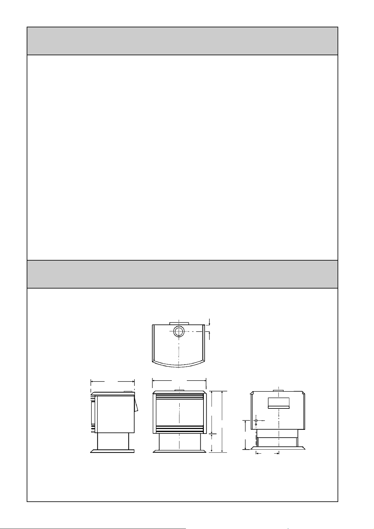
DIMENSIONS
25 ½”
3”
21”
30”
Gas inlet
3/8” FNPT
10 5/8”
9”
10.6”
4
Page 5

IMPORTANT POINTS / USAGE AND INSTALLATION MUSTS
Unpack the heater and check for damage (DO NOT INSTALL DAMAGED HEATER). If the
heater is damaged, contact your supplier for advice. Before installing the heater, check the
label for the correct gas type (see rating plate, bottom right hand side of pillar). Refer to local
gas authority for confirmation of the gas type if you are in doubt.
Included in the carton
Customer operation information
IMPORTANT Before using this product, please read this manual carefully to make sure
of proper use of the product:
1 The installation must conform with local
codes, or in the absence of local codes,
the National Fuel Gas Code, ANSI
Z223.1, or the Canadian Installation
Code, CAN/CGA -B149.
2 For information on gas type see the data
plate on the appliance.
3 This heater must not be installed where
curtains or other combustible materials
could come into contact with it. In some
cases curtains may need restraining.
4 This is a freestanding appliance
designed for installation with a vertical
flue only.
5 If you move, check the gas type in the
area where you are moving to. The local
gas authority will be able to advise on
local regulations.
6 This heater discharges a large volume
of warm air to provide even heat
distribution. If the air in the room
contains cooking vapor or cigarette
smoke, and the heater is used on a
carpet, the surface of the carpet may
become discolored. In addition, some
nylon carpets contain dyes which may be
affected by the warm air flow. Some soft
vinyl surfaces are also subject to
distortion, or discoloration by warm air.
To prevent discoloration of carpets, etc.,
a mat should be placed in front of the
appliance, extending about 30” in front
of it.
7 This heater may be installed directly onto
carpet
8 Read these rules and the instructions
carefully. Check all local codes. Failure
to follow these could cause a malfunction
of the heater resulting in death, serious
bodily injury and/or property damage.
9 This appliance is only for use with the
type of gas indicated on the rating plate.
This appliance is not convertible for use
with other gases.
10 WARNING: Any change to this heater
or its controls can be dangerous.
11 If a gas leak is suspected, turn heater
off, turn gas supply valve off at appliance
connector valve. Open windows to
ventilate area immediately and contact
your dealer or gas company.
12 DO NOT PLACE CLOTHING OR
FLAMMABLE MATERIALS,
GASOLINE AND OTHER FLAMMABLE
VAPORS AND LIQUIDS, ON OR NEAR
THE HEATER.
13 Do not spray aerosols when the heater
is in operation.
14 YOUNG CHILDREN SHOULD BE
CAREFULLY SUPERVISED WHEN
THEY ARE IN THE SAME ROOM WITH
THE HEATER.
15 LPG containers must not be installed
indoors.
16 Do not use this appliance if any part has
been under water. Immediately call a
qualified service technician to inspect
the room heater and to replace any part
5
Page 6
of the control system and any gas control
which has been under water.
17 Adequate clearances for accessibility for
purposes of servicing and proper
operation should be provided.
18 Adequate clearances around air
openings into the combustion chamber
should be provided.
19 Do not install in areas where curtains,
drapes, clothing, or other moving
flammables are within 15 inches of this
unit.
Diagram shows
minimum
15”
LEFT
15”
ABOVE
15”
RIGHT
clearances from
combustible
materials
15”
FRONT
24 The draft hood on the appliance should
be installed in the same atmospheric
pressure zone as the combustion air inlet
to the appliance and shall be located so
that the relief opening is accessible for
checking vent operation.
25 The appliance, when installed, must be
electrically grounded in accordance with
local codes or, in the absence of local
codes, with the National Electrical
Code, ANSI/NFPA 70, or the Canadian
Electrical Code, CSA C22.1
26 A gas appliance must not be connected
to a chimney flue serving a solid fuel
burning appliance.
27 Do not restrict the warm air discharge
by placing articles in front of heater.
28 This appliance must not be used for any
purpose other than heating.
20 Periodic examination of the venting
system is required.
21 The flow of combustion and ventilation
air should not be obstructed.
22 A manufactured home (USA only) or
mobile home OEM installation must
conform with the Manufactured Home
Construction and Safety Standard, Title
24CFR, Part 3280, or, when such a
standard is not applicable, the Standard
for Manufactured Home Installations,
ANSI/NCSBCS A225.1 or Standard for
Gas Equipped Recreational Vehicles
and Mobile Housing, CSA Z240.4.
23 The appliance and its appliance main
gas valve must be disconnected from the
gas supply piping system during any
pressure testing of that system at test
pressures in excess of 1/2 psi (3.5 kPa).
The appliance must be isolated from the
gas supply piping system by closing its
equipment shutoff valve during any
pressure testing of the gas supply piping
system at pressures equal to or less than
½ psi (3.5 kPa).
29 Do not allow anyone to post articles
through the louvres.
30 Do not allow anyone to sit or lean
against the appliance.
31 DUE TO HIGH TEMPERATURES, THE
APPLIANCE SHOULD BE LOCATED
OUT OF TRAFFIC AND AWAY FROM
FURNITURE AND DRAPERIES.
32 CHILDREN AND ADULTS SHOULD BE
ALERTED TO THE HAZARDS OF
HIGH SURFACE TEMPERATURES
AND SHOULD STAY AWAY TO AVOID
BURNS OR CLOTHING IGNITION.
33 CLOTHING OR OTHER FLAMMABLE
MATERIAL SHOULD NOT BE PLACED
ON OR NEAR THE APPLIANCE.
34 INSTALLATION AND REPAIR SHOULD
BE DONE BY A QUALIFIED SERVICE
PERSON. THE APPLIANCE SHOULD
BE INSPECTED BEFORE USE AND
AT LEAST ANNUALLY BY A
PROFESSIONAL SERVICE PERSON.
MORE FREQUENT CLEANING MAY
BE REQUIRED DUE TO EXCESSIVE
LINT FROM CARPETING BEDDING
MATERIAL, ET CETERA. IT IS
IMPERATIVE THAT CONTROL
6
Page 7

COMPARTMENTS, BURNERS AND
L
CIRCULATING AIR PASSAGEWAYS
OF THE APPLIANCE ARE KEPT
CLEAN.
35 The glass window shall be replaced as
one piece as supplied by the
manufacturer. See log and glass
installation on page 15.
36 Do not substitute glass, glowing embers
or logs. Use only glass, glowing embers
and logs supplied by manufacturer.
37 Caution: Do not operate unit with broken
glass.
38 WARNING: DO NOT OPERATE
APPLIANCE WITH THE FRONT
REMOVED, CRACKED OR BROKEN.
REPLACEMENT OF THE GLASS
SHOULD BE DONE BY A LICENSED
OR QUALIFIED SERVICE PERSON.
39 WARNING: Electrical grounding
instructions. This appliance is equipped
with a three prong (grounding) plug for
your protection against shock hazard
and should be plugged directly into a
properly grounded three-prong
receptacle. Do not cut or remove the
grounding prong from this plug.
TECHNICAL SPECIFICATIONS
Natural Gas Propane
Gas Input Rate: Btu/hr Btu/hr
Pilot: 200 200
Low: 11,000 9,000
High: 32,000 29,000
Minimum permissible
gas supply pressure for
purpose of input
adjustment
Gas C onnection:
Flue Termination:
Fan:
Combustion System:
Ignition System:
Operation:
Temperature control: Electronic thermostat High~Low / Off
Temperature range: Low = 50°F, 60°F~80°F, High 97°F
Safety Devices:
Fan de la y Micro computer timer
Combustion Method:
Flue Type:
Heat transfer:
Installation Type:
Flue Requirement:
Min: 7" 10"
Max: 10.5" 13"
3/8" FNPT
An approved 4" vent cap must be fitted to all installations
90 Watt 2 speed tangential
Multi port burner and ceramic logs
Continuous spark electronic ignition
Finger touch control buttons or remote control
Flame picture select option
Up / Down buttons
Flame failure- flame rod
Over heat - thermistors, thermal fuse
Power surge - 3 amp fuse
Room overheat - Automatic cut off at 104°F after 10 minutes
Naturally aspirated burner
Approved 4" B vent system
Direct radiation and forced convection
Free standing
Manufacturers minimum, 10 ft vertical.
ocal codes may have a greater
requirement and must be followed
WC WC
7
Page 8
FOR YOUR SAFETY READ BEFORE OPERATING
WARNING: If you do not follow these instructions exactly, a fire or explosion
may result causing property damage, personal injury or loss of life.
A This appliance is equipped with an
ignition device which automatically
ignites the pilot. Do not try to light the
pilot by hand
B. BEFORE OPERATING smell all around
the appliance area for gas. Be sure to
smell next to the floor because some
gas is heavier than air and will settle on
the floor.
WHAT TO DO IF YOU SMELL GAS
• Do not try to light any appliance
• Do not touch any electrical switch
• Do not use any phone in your building
• Immediately call your gas supplier from
OPERATING INSTRUCTIONS
a neighbor’s phone. Follow the gas
suppliers instructions.
• If you cannot reach your gas supplier call
the fire dept.
C. Use only your hand to push the gas
control buttons. Never use tools. If the
buttons will not activate by hand, don’t
try and repair it, call a qualified service
technician. Force or attempted repair
may result in a fire or an explosion.
D. Do not use this appliance if any part has
been under water. Immediately call a
qualified service technician to inspect
the appliance and to replace any part
of the control system and any gas control
which has been under water.
STOP Read the safety information
above.
• To turn the unit on (refer diagram
below)
Do not attempt to light the pilot by hand.
Wait for five minutes to clear out any gas.
Then smell for gas, including near the floor.
If you smell gas, STOP! Follow “B” in the
safety information above. If you don’t smell
gas, go to the next step.
Press the On / Off button. This operates
the ignition sequence.
If the appliance does not light it will
automatically turn off.
To re-attempt ignition, press the On / Off
button again.
• To adjust the heat
Press the “ “ and “ “ buttons to
increase and decrease the room
temperature setting.
• To turn the unit off
Press the On /Off button. The appliance will
turn off.
If the appliance will not operate; follow the
instructions “to turn off the gas to appliance”
and call your service technician or gas
supplier.
TO TURN OFF GAS TO APPLIANCE
Turn off the appliance by operating the On/
Off button and turn off the power at the wall
switch.
Disconnect the electric plug. This will
isolate the gas supply and prevent the
solenoid valve from opening.
8
Page 9
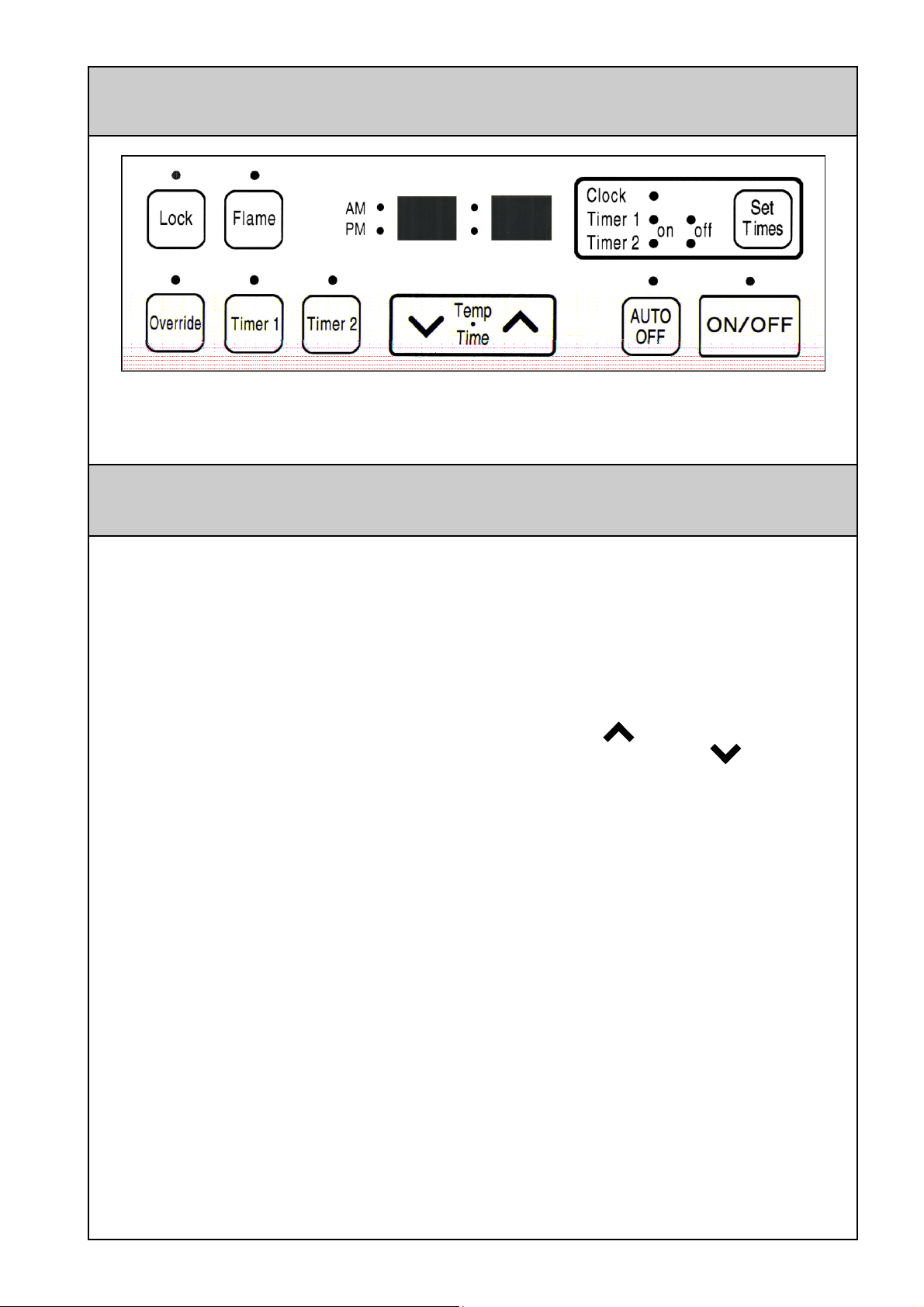
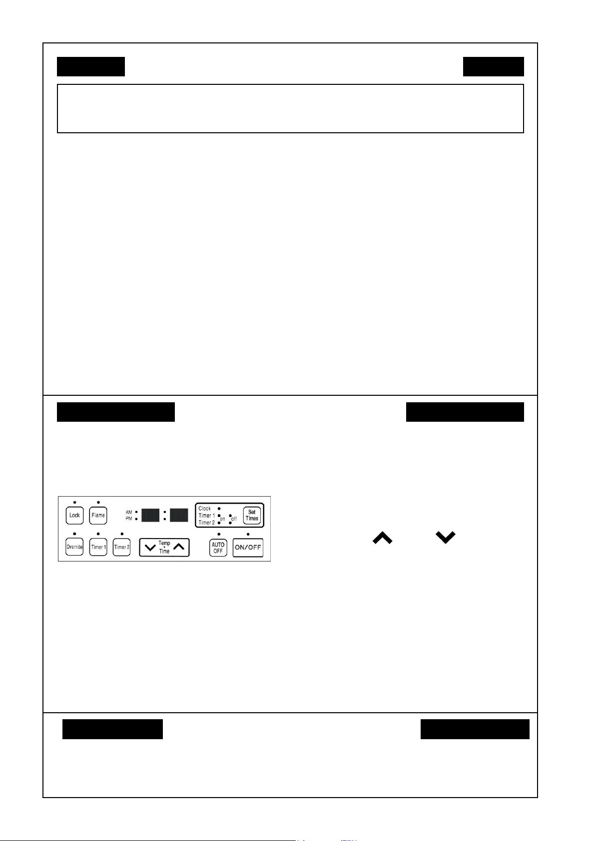
CONTROL PANEL LAYOUT
For your convenience the controls on your new Flame Fire are situated under the cover on the
top right-hand side of the fire and are accessed by simply lifting the lid. All necessary
adjustments to the operation of your fire can be made with these controls.
OPERATION
• TURNING ON
Press the ON/OFF button to operate the
unit. The ON indicator will glow green. The
spark generator will be heard before the
burner ignites and the ON indicator glows
red, indicating that the burner is alight.
Warm air can be felt coming from the
louvres. The fan will come on automatically
after 4 minutes.
If the unit does not ignite on initial use
this may be due to air remaining in the
gas supply line. The spark generator
will only continue for 15 seconds. After
this it will be necessary to press the
ON/OFF button OFF, then ON again.
• TURNING OFF
fan is running.
• ROOM TEMPERATURE
ADJUSTMENT
The room temperature and preset
temperatures are only displayed and
adjustable while the heater is running.
Press the “ “ button to increase the
temperature setting or “ “ button to
decrease the temperature setting. The
temperatures can be preset to:
a) [L] low (50°F)
b) [61°F] to [79°F] in 1°F steps
c) [H] (97°F)
Once the pre-set temperature has been
reached the burners will cycle between high
and low (or high and pilot only depending
on the auto off setting).
Simply press the ON/OFF button to switch
off the unit. The ON indicator will go out.
The convection fan will continue to operate
for several minutes after the burner has
gone out in order to cool the appliance.
Do not turn off the heater by
unplugging it from the wall. Do not
unplug the heater while the convection
• LOCK
The LOCK function will help prevent
accidental operation of the controls.
LOCK is activated by pressing the button
and the LOCK indicator will glow. To
9
Page 10

deactivate the LOCK press and hold the
button for 3 seconds until the indicator
goes off.
During normal operation the LOCK may be
activated and all controls, other than the
OFF switch, will be locked. Deactivating
the LOCK releases the controls.
you have selected AM or PM as required,
a small indicator on the left hand side of
the Digital Display indicates the AM/PM
setting.
Use the buttons again to set the minutes.
Scroll up or down using the buttons until
the correct time is reached.
If the LOCK is activated while the unit is
turned OFF, then all functions will be locked
including the ON/OFF function. If the unit
is turned OFF while the LOCK is activated,
it cannot be turned ON again until the
LOCK is deactivated.
• FLAME
To operate the FLAME function, press the
FLAME button. This function will
automatically override the thermostat and
set the unit to a default Medium High heat
setting for full visual flame effect.
• AUTO OFF
AUTO OFF is activated by pressing the
button and the AUTO OFF indicator will
glow when on.
When the AUTO OFF function is on and
the room temperature reaches or exceeds
the pre-set temperature then the burners
will reduce to pilot only.
Press the TIMER SET button five times to
lock in the time. The CLOCK and TIMER
indicators will go out. A small indicator on
the digital display will flash to show that the
clock is operating.
• TIMERS / PREHEAT
This heater has two programmable timers,
these allow you to set a start and finish
time. The temperature is preset each time
the timers are activated.
There is also a preheat function that
measures the temperature of the room and
estimates the time it will take to bring the
room up to the preset temperature by the
programmed start time.
This means that the heater may start
heating an hour or more before the
programmed start time.
• PROGRAMMING THE ON / OFF
TIMERS
When the AUTO OFF is off then the burners
will reduce to the front (ember) burner and
pilots.
• SETTING THE CLOCK
When the appliance is first plugged in or
after a power failure, the Digital Display will
show
Press the SET TIMES button once, the
Clock indicator will flash. Press and hold
the “ “or “ “ button, the minutes will
begin to count up or down until they reach
00, the time will now change by one hour
increments.
Release the button when the correct hour
shows on the Digital Display. Confirm that
--:--.
Before programming the Timers you must
ensure that the clock has been set to the
correct time.
Press the SET TIMES button twice. The
digital display will show AM 6:00 and the
TIMER 1 - ON indicator will flash.
Set the desired start time the same way
as for setting the clock. Be aware that the
heater may start up much earlier than the
programmed start time due to the preheat
function, as explained earlier.
Press the SET TIMES button again, the
TIMER 1 - OFF indicator will flash.
Set the desired stop time the same way
as for setting the clock.
Press the SET TIMES button once to
10
Page 11

proceed to TIMER 2 - which is
programmed in the same way - or three
times to return to the clock display. This
must be done within 1 minute of setting the
time to lock it into the memory.
The digital display will show the current
time. A small indicator on the digital display
will flash to show that the display has
returned to the clock.
After setting timer 2 the SET TIMES button
must be pressed once within one minute
of programming to lock in the times and
return to the clock display.
The timers operate over a 24 hour period,
and will activate 7 days a week when set.
• OPERATING THE TIMERS
again when the power comes back on, but
the time will be slow by the duration of the
power failure. To set the clock to the
correct time after the power has come
back on, simply follow the instructions on
page 10.
• OVERRIDE
This function is intended to be used to
manually override the current operation of
the heater. For example; If the heater is in
stand-by mode (ie. between finishing time
and starting time of a timer), and the
OVERRIDE button is selected, then the
heater will begin to operate and heat the
room.
Press the OVERRIDE button to activate.
The indicator light will flash when active.
Before operating the timer(s), the clock
time must be correct and a starting time
and finishing time for the timer(s) must be
programmed, see page 10. Both timers
operate in the same way.
Ignite the heater and select the preset
temperature as for normal operation.
Press the timer 1 and / or timer 2 button(s).
The timer indicator(s) will glow and the unit
will change to stand-by mode. The burners
will extinguish and the ON indicator will
change from red to green. The display will
show the start time for the selected timer
briefly before returning to the clock display.
When the heater is in stand-by mode, you
can display and change the clock and the
on and off times for both timers in the same
way as described earlier.
The timers can be deactivated by either
pressing the timer button(s) that you want
to deactivate or by turning the heater off
using the ON/OFF button.
NOTE: If there is a power failure, the
system memory will retain the Timer
programs, and the clock will stop at the
time the power goes off. The clock will start
To manually deactivate the OVERRIDE
press the OVERRIDE button again. The
OVERRIDE indicator will go out, and the
heater will return to stand-by mode.
The heater will continue to operate on
OVERRIDE until the OVERRIDE button is
pressed again, or one of the timers takes
over the operation of the heater. This
means that the OVERRIDE mode will
automatically turn off if a programmed
starting time is reached. The heater will
then return to operating at times
programmed into the timer(s). Turning the
heater off will also deactivate the
OVERRIDE.
• REMOTE CONTROL
The remote control can only be used for
manual operation of the heater. If the
heater is in stand-by (timer) mode then only
the OFF button will work. Pressing the OFF
button when the heater is in stand-by mode
will deactivate the timers and the heater
can now be operated manually.
The ON and OFF buttons on the remote
work in the same way as the ON / OFF
button on the control panel as do the “
“ and “ “ buttons.
11
Page 12

ON BUTTON
Operates the unit
manually.
OFF BUTTON
Stops unit
manually.
TEMPERATURE
ADJUSTMENT
Increases or
decreases
the temperature
setting.
NOTE: Some fluorescent lights may
interfere with the transmission of remote
control signals, in this case changing the
position from which you are operating the
remote control may help.
Avoid getting the remote control wet, or
dropping it.
The remote control works within 15 feet and
an angle of 40° to the receiver on the unit.
• TO REPLACE REMOTE CONTROL
BATTERY
The battery is held in a clip that slides out
the bottom of the remote control. The clip
is removed by inserting a coin or similar
into the recess in the back of the remote
control and sliding downwards.
The battery must be of type CR 2032 and
will only operate if installed the right way
up, as shown below.
Remove the battery if the remote control is
not going to be used for a long period. This
will help avoid damage from leaking
batteries.
REMOTE CONTROL
BACK
BATTERY
Note the + side of the battery is
facing the rear of the remote
control
12
Page 13

LOCATION
When positioning the heater, the main points governing the location are:
1. Flue connection and proper venting
2. Warm air distribution.
3. Adequate air supply.
4. The heater must not be installed where
curtains or other combustible materials
could come into contact with it. In some
cases, curtains may need restraining.
See below for minimum clearances
required.
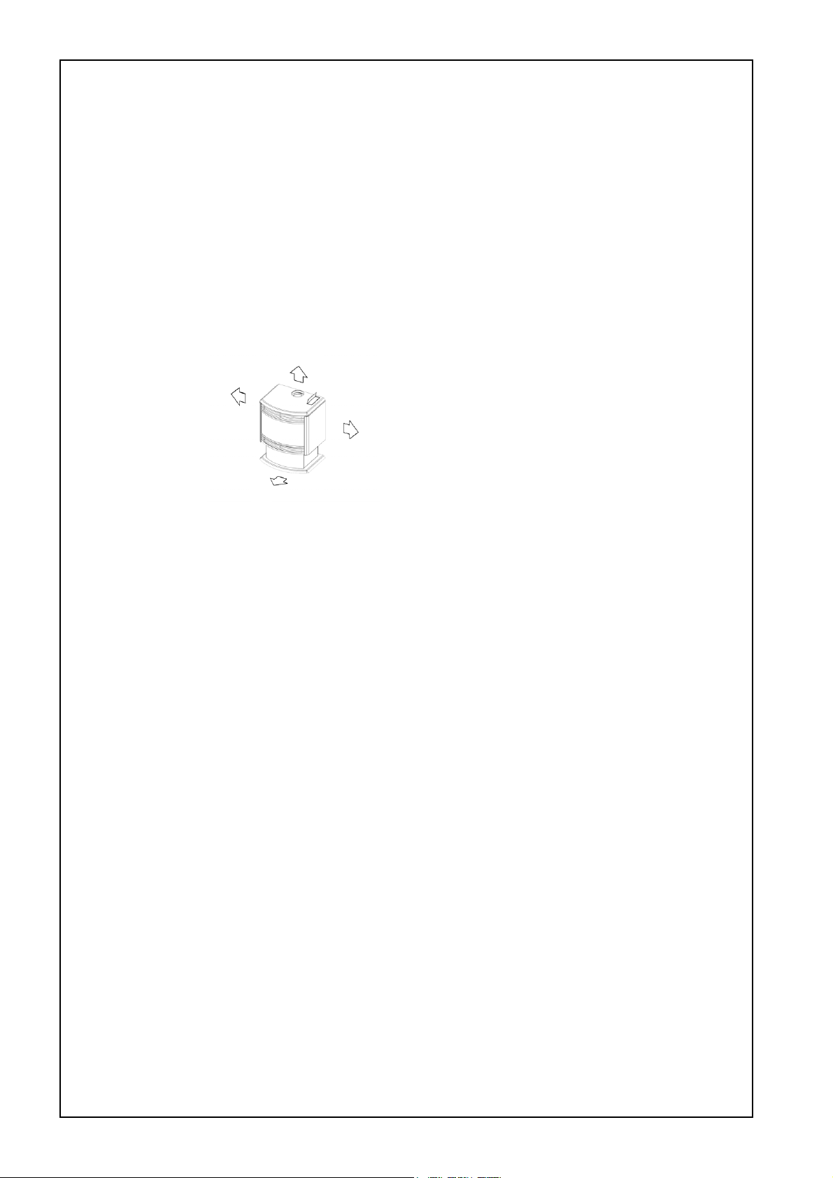
15”
ABOVE
15”
LEFT
15”
RIGHT
5. The heater is not designed to be built
into bookcases or shelves or any
combustible opening.
6. Check that room ventilation complies
with local regulations.
7. Installation location shall provide
adequate combustion and ventilation air.
8. A gas appliance must not be connected
to a chimney flue serving a separate
solid-fuel burning appliance.
15”
FRONT
13
Page 14

VENTING
Use only an approved B vent system
• Position the heater.
• Suspend a plumbline from the ceiling to
the centre of the flue socket.
• Mark the centre of the flue in the ceiling.
• Make a small hole in the ceiling and
double check that the flue system will be
at least 1” clear of combustible
materials.
• Cut the hole for the flue.
• Fit the ceiling plate, flue and decorative
cover.
The decorative cover must be able to slide
up to give access to the flue collar. The
inner flue must be supported independently
of the heater but allowing sufficient
movement to allow connections to and
disconnections from the flue collar.
It is recommended that the flue be
installed vertically only. If installation
prevents this then there must be at
least 4 feet of vertical flue before any
bends. The flue must not fall below
horizontal at any stage. There must not
be more than 2 bends in any system.
Any horizontal section of flue must be
less than 1/3 the length of vertical flue
which follows it.
See below diagram
An approved B vent system must be
attached by mechanical means to the flue
spigot and sealed using an approved high
temperature sealant.
**
X
X/3 maximum
10 ft
4 ft
minimum
maximum
2 bends
Minimum **
** Refer to local codes for other minimum
requirements.
GAS CONNECTION
• RUN GAS SUPPLY
For pipe sizing, refer to your local gas
installation codes.
• PURGE SUPPLY OF AIR AND
DEBRIS
All foreign materials such as filings must
be purged from the gas supply, as they may
cause the gas valve to malfunction.
A means to measure the gas pressure
immediately upstream of the supply
connection to the appliance shall be
provided by the installer.
Connect and tighten union.
On completion of work, check for gas
leaks.
Use a soapy solution all gas connections.
Leaks will be visible when the soapy
solution forms bubbles. When finished wipe
soapy solution with rag to remove residue.
Gas inlet
3/8” FNPT
10 5/8”
10.6”
14
Page 15

LOG INSTALLATION
The logset is packed inside the unit and
the packaging must be removed prior to
installing the logset in its correct position.
• Open both side panels.
• Remove fasteners on both sides of the
top glass retainer.
• Lift retainer away from unit.
• Loosen screws on bottom glass retainer.
• Carefully lift glass out of bottom channel.
• Carefully remove log packaging.
The logset has two holes underneath for
location onto the pins inside the unit.
Place the logset into the unit ensuring that
the locating pins enter the two locating
holes on the bottom face of the logset.
Gently place loose ember bed material
in front of the front log only. Do not
pour as dust particles from the plastic
bag may block the burner ports.
Level it with a pencil or screwdriver and
remove excess material.
Note: The ember bed material must be
placed after the logs are fitted. If the logs
are to be removed for any reason, the
ember bed material must be removed first
and replaced after the logs are refitted.
Any material that prevents the logs sitting
flat on the burner top can upset the burning
pattern and performance of the heater.
• Replace glass and top glass retainer,
tighten bottom glass retainer screws.
Note: Fit glass so that the joint in the glass
seal is at the bottom.
• Take care not to damage seals.
• Reinstall side panels.
WARNING: Failure to position the parts
in accordance with these diagrams or
failure to use only parts specifically
approved with this appliance may result in
property damage or personal injury.
Note: When first lighting the heater, the
logs need to be burnt in, which may take
approximately 2 hours. The flame color
may change after the initial burning in
period.
15
Page 16

TESTING AND COMMISSIONING
• TESTING PROCEDURE
Turn gas supply on and plug the unit into
the power supply. (Caution 115V)
• TO CHECK BURNER PRESSURE
• Refer to rating plate.
• Remove the wiring cover panel.
• Remove test point plug and attach
manometer to test point.
The test point is on the bottom front face
of the gas valve.
• Light heater, turn to High heat setting and
check pressure.
• If adjustments are necessary, the
regulator is situated on the front of the
gas control.
• After checking pressure, turn the unit off,
remove manometer and replace test
point plug.
• Turn the heater on and off a few times to
check ignition.
It is the responsibility of the installer
to check that under normal operating
conditions of the appliance, all flue
gases are exhausted to the outside
atmosphere and that there is no
spillage of combustion gases into the
room.
COMMISSIONING
• INSTALLATION / COMMISSIONING
CHECKLIST
Complete the installation checklist and the
installer details on page 27 and make sure
that this instruction book is left with the
customer.
• INSTRUCT CUSTOMER ON USE OF
UNIT
Explain to the customer about use and care
of unit. Make sure the customer
understands the instructions.
• EXPLAIN
Ignition (on / off), adjusting heat level,
programming timers, flame setting, auto
off, lock, override and the remote control.
• When you are satisfied that the heater is
working correctly, reassemble panels.
• All burner aeration is factory preset and
cannot be adjusted.
• If you are unable to get the unit to operate
correctly, refer to Troubleshooting on
Page 20, before contacting your local
service contact as listed on Page 3.
• It may take approximately 2 hours for the
logs to achieve their full flame pattern
and glow.
• During the initial burning in period,
some smoke and smell may be
experienced. The heater should be
run on the high position in a well
ventilated room until these
dissipate.
NOTE:
THE MANUFACTURE RESERVES THE
RIGHT TO CHANGE OR MODIFY
SPECIFICATIONS WITHOUT NOTICE
16
Page 17

MAINTENANCE INSTRUCTIONS
IMPORTANT MAINTENANCE INSTRUCTIONS
ANNUAL INSPECTION
The unit should be inspected at least once
a year by a qualified service technician
including inspection of the flue system.
The appliance area must be kept clear and
free from combustible materials, gasoline
and other flammable vapors and liquids.
• CLEANING INSTRUCTIONS.
Before cleaning, make sure the electrical
power and gas are turned off and that the
unit has cooled down.
WARNING:Do not clean the glass or unit
when hot.
Do not remove any internal wiring covers.
Do not use abrasive cleaners.
Do not use solvent based cleaners.
A heater should not be used if you suspect
there may be a problem, and a service
agent must be called to investigate the
cause of the problem.
Normal
Abnormal
• OUTER CASE
The outer case of the fire place should be
cleaned with a soft, damp cloth.
Do not use aerosol polishes to clean the
casing while the fire is in operation.
Do not damage or distort any part of the
heater
Do not use wet cloth or spray cleaners on
burners
• VENT MAINTENANCE
The flue should be inspected annually for
blockages and signs of damage.
• VISUAL INSPECTION OF FLAME
Check that the pilot and burner flames are
operating normally.
Normal
Abnormal
The main burners are designed to produce
some yellow flame but should not produce
smoke or excessive soot.
NOTE: The flames may take up to 15
minutes to settle from ignition when the
heater is cold.
• ELECTRIC MOTOR MAINTENANCE
If the flames appear either very short or very
long and streaky or are producing smoke
or soot deposits then there may be a
problem with the heater or the gas supply.
Motors are permanently lubricated and
needs no lubrication.
Keep fan and motor free of dust and dirt,
clean annually.
17
Page 18

The heater should be serviced
annually only by an authorised person.
• GLASS REPLACEMENT AND
CLEANING. (May be performed by the
owner)
It is best to handle the glass with clean
gloves to avoid smearing the glass with
finger prints which might show after
replacement.
Refer diagram opposite
Loosen the side panel retaining screws.(1)
Access can now be obtained to the two
top glass retaining screws.(2)
4
2
3
1
2
1
• FAN REMOVAL (Only to be carried
out by qualified service technician)
Gently lift the retaining trim away from the
glass.(3)
Carefully lift the glass out of the bottom
retaining channel, taking care not to
damage the fiber seal on the perimeter of
the glass.(4)
The glass may be cleaned with a damp
sponge and soapy water. If the seal is
damaged it should be replaced. Remove
any soot deposit from the log set with a
soft brush and a vacuum cleaner. Soot
deposit may indicate that the flue is not
drawing properly. Check the flue for correct
operation.
It is best to handle the glass with clean
gloves to avoid smearing the glass with
finger prints which might show after
replacement.
Refer diagram below
NOTE: The fan has a permanently
lubricated bearing. DO NOT OIL.
Open the right-hand panel of the heater (1)
and undo the cable connection between the
fan assembly and wiring loom.(2)
On the back of the heater loosen the 4
Phillips screws holding the fan bracket.(3)
The fan, complete with the fan support
bracket, can now be removed for cleaning
and replaced as is necessary.
Reassemble in reverse order.
NOTE: When replacing the glass make
sure that the joint of the fiber seal is at the
bottom of the glass.
• BURNERS
Due to the design of the burners in this
heater, they do not require cleaning by the
owner. The burners should be cleaned
once a year by a qualified service agent.
18
2
1
3
3
Page 19
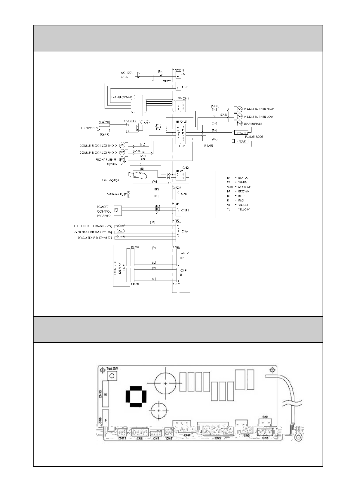
WIRING DIAGRAM
PCB LAYOUT
Caution: Label all wires prior to
disconnection when servicing
controls. Wiring errors can cause
improper and dangerous
operation.
Verify proper operation after
servicing.
19
Page 20

WIRING DIAGRAM-LADDER
TROUBLE SHOOTING
SYMPTOM CAUSE SOLUTION
No power present Ensure power cord is plugged in and turned on
No gas present Ensure gas supply is turned on
Burner will not light
Smell of gas Leaking gas Turn gas off at m eter and call installer
Fan not working
Fan does not stop Heater cooling down
Small soot deposit Normal operation No action required
Soot deposit forming on
glass or logs
Condensation on glass Normal operation Allow fire to warm up
Streaky lines on glass Normal operation Remove and clean glass
Digital error message on
control panel
power cut Re-ignite after power is restored
Air in gas pipe Purge air (installer)
Ignition failure Repeat lighting procedure.
Heater still warming up
Inadequate flue system
Log misalignment Call service department/agent
Incorrect gas pressure
Electronic fault detected Refer Error Messages page 21
The fan is programmed to start after the heater has
been operating for 4 minutes.
The fan is programmed to continue running for 4
minutes after the burners have been extinguished
NOTE:
If you have any other faults or problems, please refer to your Installer or local qualified service agency
20
Page 21

ERROR CODES
• ERROR CODE MESSAGE
The Flame Fire ETR has the ability to check its own operation continuously. If a fault occurs,
an Error Message will flash on the Digital Display of the control panel. This assists with
diagnosing the fault, and may enable you to overcome a problem without a service call. Please
quote the code displayed when enquiring about service.
Error code Probable cause Comments
11
12
14
16
31
32
33
70
71
72
Ignition failure
Flame failure
Overheat Service call
Room overheat
Room temperature sensor faulty
Overheat temperature sensor faulty Service call
Faulty ON / OFF switch Service call
Faulty soleniods Service call
Faulty flame rod Service call
Check gas is turned on.
Service call if repeated
Check gas is turned on.
Service call if repeated
Lower rom temperaure to
less than 104°F
Service call
Service call
73
99
--:--
In all cases, you may be able to clear the Error Message simply by turning the unit OFF, then
ON again. If the Error Message still remains or returns on the next operation, please contact
your nearest service contact and arrange for a service call.
Communication error Service call
Flue block Service call
Power failure Service call
21
Page 22
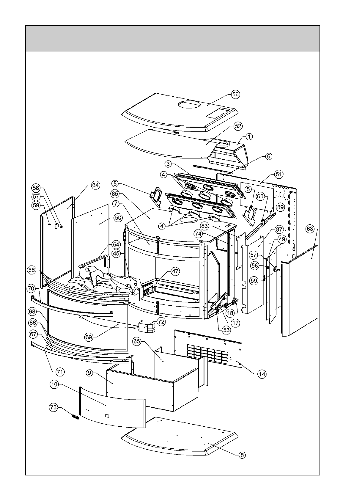
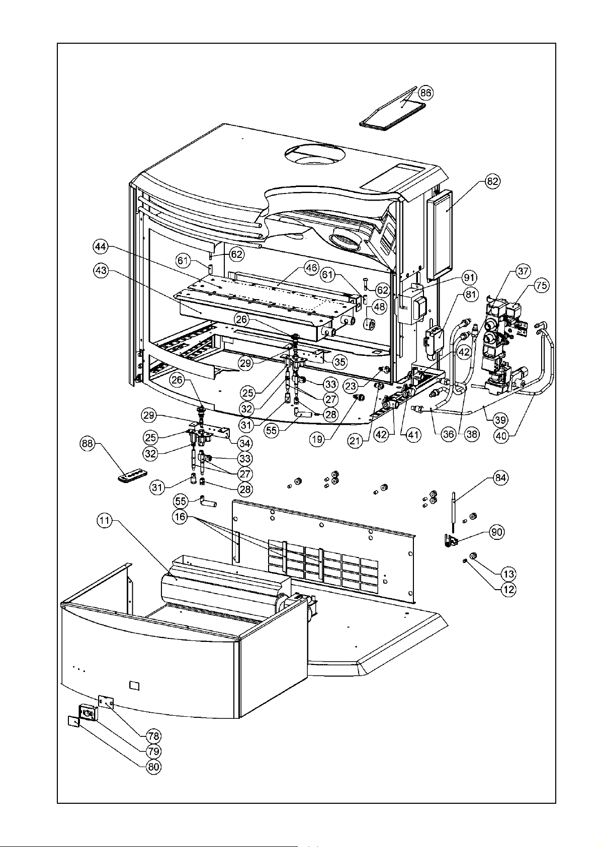
EXPLODED DIAGRAMS
22
Page 23
23
Page 24

SPARE PARTS LIST
ITEM NO. QTY. PART NO.
1 1 7992-1 FLUE SPIGOT ASSY FS NAT USA
2 1 7074 HEAT EXCHANGER FRONT ASSY 3+3H
3 1 7075 HEAT EXCHANGER REAR ASSY 3H
4 6 6624 BURNER EXCHANGER TRANSFER TUBE
5 2 6625 BURNER HEAT EXCHANGER BRACKET
6 1 7028-5 FLUE SPIGOT DRAUGHT DIVERTER
7 1 7926 COMB CHAMB ASSY FS ETR USA PAI
8 1 7022V BASE PANEL FS VIPER BLACK
1 7022SP BASE FS SP SILVER
9 1 7020V PILLAR FS VIPER BLACK
1 7020SP PILLAR PAINTED SP SILVER
10 1 7471V PILLAR FRONT FS35ETR VIPER BLACK
1 7471SP PILLAR FRONT FS35ETR SP SILVER
11 1 7141 FAN QLN65/0030-3038LH MVL 110V
12 9 7130 FAN MTG SLEEVE
13 9 7129 FAN MTG GROMMET
14 1 7069V FAN MT BRKT FS MVL VIPER BLACK
1 7069SP FAN MT BRKT FS MVL SP SILVER
15 9 9028 SCREW 8X5/8 MUSH HEAD 33611923
16 3 6651 CUSHION RUBBER REH210
17 1 7950 INJECTOR BLOCK BRKT FRONT MKII
18 1 7951 INJECTOR BLOCK BRKT REAR MKII
19 1 7338 INJECTOR BRAY 260 CAT33 MULTI NG
1 7175 INJECTOR BRAY 120 CAT23 SINGLE LP
21 1 7337 INJECTOR BRAY 560 CAT33 MULTI NG
1 7183 INJECTOR BRAY 200 CAT33 MULTI LP
23 1 7906 INJECTOR BRAY 180 CAT23 SINGLE NG
1 7175 INJECTOR BRAY 120 CAT23 SINGLE LP
24 6 9064 SCREW M4 X 8 PHPMZ SPRINGWASH
25 2 7870 PILOT BODY TOP CONVERTIBLE
26 2 7871 PILOT CONVERTIBLE HOOD 2 FLAME
27 4 7875 ELECTRODE
28 2 7876 ELECTRODE NUT (S.I.T)
29 2 7872 INJECTOR NG 51 NG
2 7873 INJECTOR LPG 31 LP
31 2 7900 ELECTRODE NUT ETR
32 2 7902 SPACER ELECTRODE PILOT
33 2 7986 ELBOW 6mmx1/8"BSPT BFM690602
34 1 7904 PILOT BRACKET FRONT USA
35 1 7985 PILOT BRACKET REAR ETR USA
36 1 7928 GAS SUPPLY TUBE A FSETR
37 1 7929 GAS SUPPLY TUBE B FSETR
38 1 7930 GAS SUPPLY TUBE C FSETR
39 1 7943 PILOT TUBE FSETR FRONT
40 1 7944 PILOT TUBE FSETR REAR
41 1 7952 INJECTOR BLOCK A+B
42 2 7953 INJECTOR BLOCK A+C
43 1 7924 FRONT BURNER US ASSY PAINTED
44 1 4990 MAIN BURNER NG/LPG USA FLAME
45 1 7044 CERAMIC LOG SET c/w GRANULES
46 1 6384 BURNER COSYPANEL
47 1 7276 BURNER BRACKET
48 1 7258 AERATION SLEEVE SHORT
49 1 7508 HEATSHIELD RH FS35ETR
DESCRIPTION
24
Page 25
51 1 7988V REAR PANEL FS35ETR VIPER USA BLACK
1 7988SP REAR PANEL FS35ETR SP USA SILVER
52 1 7472 AIR GUIDE LOW ER FS35ETR
53 1 7062 HEATSHIELD LOWER RH FS ETR
54 1 7060 HEATSHIELD LOWER LH FS
55 2 7564 ELECTRODE S LEEVE
56 1 7482V TOP PANEL ASSY FS35ETR VIPER BLACK
1 7482SP TOP PANEL ASSY FS35ETR SP SILVER
57 2 7136 MAGNET FS
58 2 9200 NUT M8 HEX MACH MS ZINC PLATE
59 2 9025 SCREW 8 X 5/8 S/TAP PANHEAD ZP
60 4 7050 HINGE BKL
61 2 7240 LOG LOCATING SLEEVE
62 2 9115 SCREW M5 X 25 PHSMZ PHIL
63 1 7019V SIDE PANEL RH FS35 VIPER BLACK
1 7019SP SIDE PANEL RH PAINTED FS35 SP SILVER
64 1 7018V SIDE PANEL LH VIPER BLACK
1 7018SP SIDE PANEL LH PAINTED FS SP SILVER
65 1 7063 FAN INLET GUIDE FS
66 5 7029 LOUVRE TUBE FS 9.5 GOLD BLACK
5 7029BN LOUVRE TUBE FS 9.5 BLK NICKEL SILVER
67 1 7099 LOUVRE TUBE RD 15.8 GOLD BLACK
1 7099BN LOUVRE TUBE RD 15.8 BKL NICKLE SILVER
68 1 4996 GLASS PANEL ASSY IB35/FS35
69 1 7004 BURNER DIVERT PANEL PTD ETR
70 1 7033 GLASS RET TOP ASSY PAINTED
71 1 7037 GLASS RET BOTTOM ASSY PAINTED
72 1 7518 FRONT PILOT SHIELD ETR
73 1 5327G BRAND BADGE GOLD
74 1 7513 PARTITION PANEL FS35ETR
75 1 4991 GAS CONTROL ASSY LP US FS35ETR NG
1 4992 GAS CONTROL ASSY NG US FS35ETR PROPANE
76 2 6308 O RING MAIN GAS
77 2 6313 GAS TUBE RETAINER
78 1 7536 RECEIVER UNIT ETR-015X01
79 1 7537 RECEIVER UNIT HOLDER 35ETR-016
80 1 7539 RECEIVER COVER 35ETR-017
81 1 7542 SPARK IGNITOR ETR EI-145
82 1 7544 PCB ASSY ETR 35ETR-020
83 1 7507 PCB MOUNTING BRKT ASSY FS35ETR
84 1 7549 THERMISTOR OH SWIT.35ETR-023
85 1 7491 AIR GUIDE FS35ETR
86 1 7545 CONTROL UNIT ASSY 35ETR-010BX0*
1 7545S CONTROL UNIT 35ETR-010B SILVER**
87 1 7512 WIRING COVER FS35ETR
88 1 7541 REMOTE CONTROL 556F-2005
89 1 7514 FAN DIVERTOR PANEL FS35ETR
90 1 7540 THERMISTOR HOLDER RC-312-628
91 1 7899 TRANSF. USA ETR ET-277 100V
25
Page 26

INSTALLATION NOTES
26
Page 27

INSTALLATION / COMMISSIONING CHECKLIST
1. Was a fireplace inspection carried out?
(i.e. clearances, combustibles etc.)
2. Was a manufactured flue system installed?
3. Has specified gas pressure been set?
4. Are decorative logs located correctly on pins?
5. Have ember granules been placed and free of dust and
powder?
NO YES
6.Has the appliance been test fired for correct operation
(All burners light without delay)
7. Is the end-user fully aware of operating procedure?
INSTALLER DETAILS
Company name: _______________________________________________________
Installers name: ______________________________________________________
Address: ______________________________________________________
______________________________________________________
Phone: __________________ Mobile: ___________________
Permit number for installation:_________________
Signed: __________________________ Date: ___________________
27
Page 28

zx
Part Number 7917
 Loading...