

Page 1
Flame Fire
Operating and Installation Instructions
Freestanding Royale (Australia)
Timberfl ame FS 35 (New Zealand)
Table of Contents
Customer Instructions
Operation
Safety Points
Troubleshooting
Installation Instructions
Location
Flueing
Gas Connection
Log Installation
Testing & Commissioning
Technical Data
Service Contacts
Installation Checklist
Installer Details
IMPORTANT
This appliance shall be installed in accordance with:
• Manufacturers Installation Instructions.
• Local Gas fi tting regulations.
• Municipal Building codes.
• AGA Gas Installation Code AG601 - NZ 5261.
• Any other relevant statutory regulation.
• This appliance must only be installed, serviced and removed by an
authorised person.
• For Australian installation, this appliance must be installed with
the supplied wire dressguard.
3
4
5
6
7
7
8
9
10
10
12
12
Page 2

LIMITED WARRANTY
TERMS AND CONDITIONS
1. During the 24 month period from date of purchase and subject to clauses 2 and 3 below,
Rinnai New Zealand Limited (“Rinnai”) will, at its own discretion, either replace or repair any
defective product at no charge to the customer.
2. This warranty covers manufacturing defects only. This warranty will not apply if (for example)
the product has been improperly installed or is otherwise installed contrary to manufacturer’s
recommendations, has been damaged during or after installation, has not been operated in
accordance with operating instructions, or has been subjected to damage or abuse beyond that
expected from conditions of normal use.
3. Warranty claims may be invalid if not accompanied by details of the installing or supervising
gas fi tter’s registration number and the gas fi tting certifi cation number.
4. This warranty commences from the date of purchase. Proof of purchase is required at the time
of any warranty claim.
5. Servicing of the product is to be carried out by a Rinnai authorised service centre.
All Rinnai appliances meet or exceed the safety standards required by New Zealand gas and electrical regulations.
The company is constantly improving its products and as such specifi cations are subject to change or variation
without notice.
Please keep these instructions in a safe place for future reference.
RECORD AND ATTACH YOUR PROOF OF PURCHASE BELOW:
Your Retailer:
Name:
Address:
Telephone: ( )
Date of Purchase: / /
Page 3
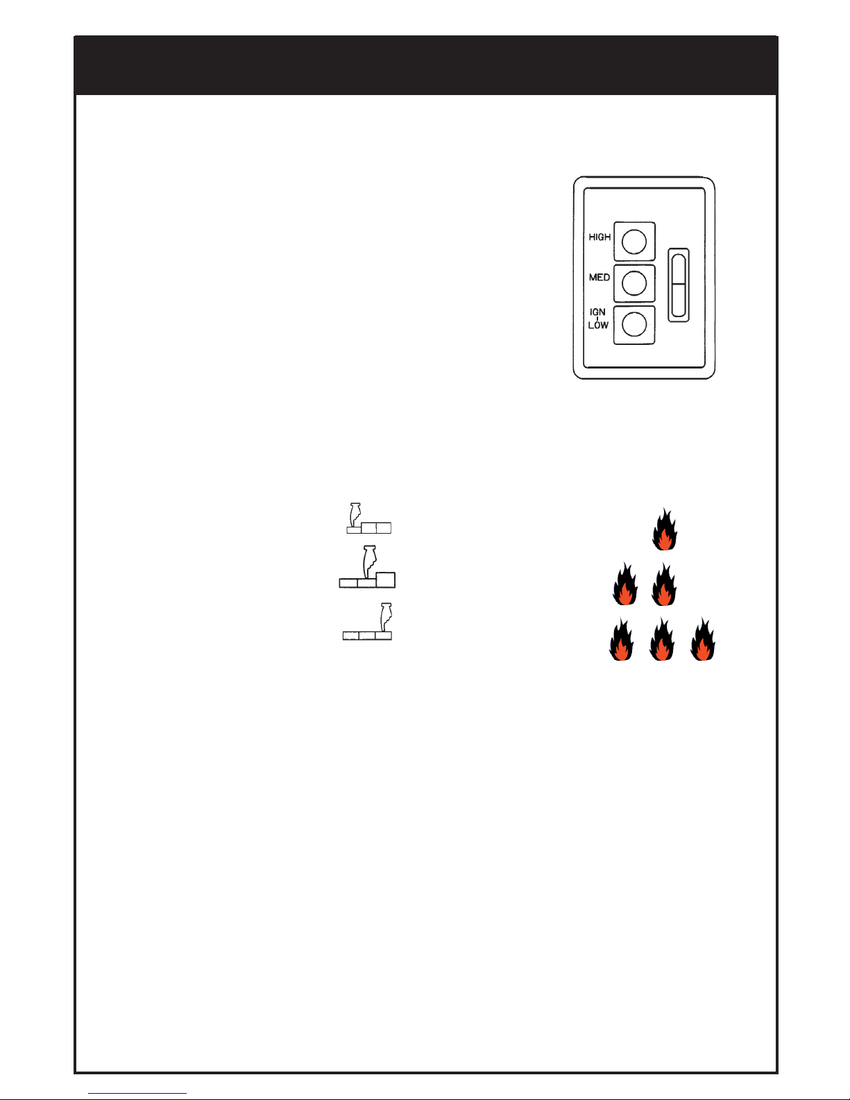
1. Ignition/Low 16 MJ/h High / Off / Low
2. Medium 24 MJ/h High / Off / Low
3. High 35 MJ/h High (Auto)
For your convenience the controls on your new Flame Fire are situated under the cover
on the top right-hand side of the heater.
All necessary adjustments to the operation of your heater can be made with these controls.
•
IGNITION
Press the front control button fi rmly. This operates the built-in
safety device and starts the electronic spark. The centre burner
will ignite. Check that the burner has lit and continue to hold the
button down for up to 15 seconds. The spark will continue while
the button is held down.
If the burner does not remain alight, push the button again and
release it. This will return it to the “OFF” position. Wait 30
seconds, then repeat the ignition procedure.
(The ignition button must be in the “OFF” position before attempt-
ing re-ignition).
• TO INCREASE THE HEAT
Press the control buttons in order from front to rear, this will ignite additional burners as
shown in the diagram.
There is no need to hold the buttons for 15 seconds when increasing the heat.
SETTING INPUT BUTTONS FAN BURNER PATTERN
• TO DECREASE THE HEAT
This is simply done by releasing the control buttons in order from rear to front.
• TO TURN THE UNIT OFF
Press and release the buttons in order from back to front until all 3 buttons are in the “OFF”
(UP) position. The fan will continue to operate until the heater cools off.
Ensure all burners are extinguished.
• POWER FAILURE
Your Rinnai Flame Fire can be used on the low and medium settings during a power failure.
However, if switched off, it cannot be relit unless power is available.
The appliance is protected by an overheat switch, and may cut out if used on the HIGH setting.
OPERATION
• FAN OPERATION
On the LOW and MEDIUM heater settings, the fan can be operated on the LOW speed or
OFF.
NOTE: When the heater is turned on, there will be a delay in the operation of the fan. This
ensures that a cold draft does not occur while the heater is warming up.
When the heater is turned off, the fan will continue to run until the heater has cooled down.
3
Page 4
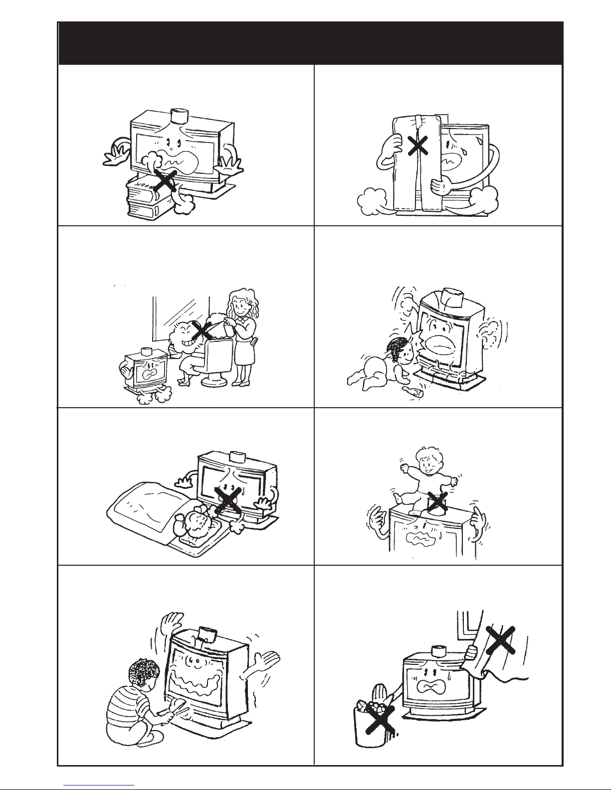
Do not restrict the warm air discharge by
placing articles in front of the heater.
This appliance must not be used for any purpose other than heating.
Do not spray aerosols whilst the heater is
operating. Most aerosols contain butane gas,
and can be a fi re hazard if used near the heater
when it is in use.
Young children should be supervised at all
times. Hand or body contact with the louvres
should be avoided.
Do not allow young children or the infi rm to
sleep directly in front of the heater.
Do not allow anyone to sit on or lean
against the appliance.
Do not allow anyone to post articles
through the louvres.
Do not allow curtains or other fl ammable
or combustible materials to come into
contact with the heater.
SAFETY POINTS
4
Page 5

• NOTE:
If you have any other faults or problems, please refer to your Installer.
• OUTER CASE
The outer case of the heater should be cleaned with a soft, damp cloth.
Do not use aerosol polishes to clean the casing while the heater is in operation.
• CLEANING INSTRUCTIONS.
Before cleaning, ensure the power and gas are turned off and that the heater has
cooled down.
Do not remove any internal wiring covers.
Use only non abrasive cleaners.
Do not use solvent based cleaners.
• GLASS CLEANING
After a period of use the glass panel may require cleaning. When your heater is cold, refer to Page 8 and
follow the initial log installation instructions to remove side panels and glass for cleaning purposes.
TROUBLESHOOTING
SYMPTOM CAUSE
SOLUTION
Burner will not light No power present
Ensure power cord is plugged in
and turned on
Power cut Re-ignite after power is restored
Air in gas pipe Purge air (installer)
Ignition Failure
Repeat lighting procedure
(refer page 2)
No gas present
Ensure gas supply is turned on
Smell of gas
Leaking gas
Turn gas off at meter and
call installer
Fan not working
Heat switch not
activated
Allow heater to run on HIGH
for 15 minutes minimum.
Fan not turned on
Ensure appliance fan switch
is in ON position
Soot deposit forming
on Glass or Logs
Inadequate Flue System
Condensation on Glass Normal operation
Allow heater to warm up
Streaky lines on Glass
Normal operation
Remove and clean Glass
5
Log Misalignment
Incorrect Gas Pressure
Call Rinnai Service Dept./Agent
Small Soot Deposit
Normal operation No action required
Page 6

YOur
LOCATION
When positioning the heater, the main points governing the location are:
1. Flueing.
2. Warm air distribution.
3. The heater must not be installed where curtains or other combustible materials could come
into contact with it. In some cases, curtains may need restraining.
See below for minimum clearances required.
4. The heater is not designed to be built into bookcases or shelves or any combustible
opening.
5. Check that room ventilation complies with local regulations.
6. Check that an EARTHED power point is within 1500mm. of the right hand side of the
heater.
7. The heater does not require any additional hearth or fl oor protection.
6
Page 7

FLUEING
7
• RUN GAS SUPPLY
For pipe sizing, refer to your local gas installation
codes.
Copper supply should be run leaving a fl ared connection
at the position shown.
PURGE SUPPLY OF AIR AND SWARF.
All foreign materials such as fi lings must be purged
from the gas supply, as they may cause the gas valve to
malfunction.
Connect and tighten union.
On completion of work, check for gas leaks.
GAS CONNECTION
• This heater requires a minimum 3m. fl ue.
• Position the heater.
• Suspend a plumbline from the ceiling to
the centre of the fl ue socket.
• Mark the centre of the fl ue in the ceiling.
• Make a small hole in the ceiling and double
check that the fl ue system will be at least
25 mm clear of combustible materials.
• Cut the hole for the fl ue.
• Fit the ceiling plate, fl ue and decorative
cover.
The decorative cover must be able to slide up
to give access to the fl ue spigot. The inner
fl ue must be supported independently of the
heater but allowing suffi cient movement to
allow connections to and disconnections from
the fl ue spigot.
Page 8

LOG INSTALLATION
The logset is packed inside the heater and the packaging must be removed prior to
installing the logset in its correct position.
• Open both side panels.
• Remove fastenings on both sides of the
top glass retainer.
Lift retainer away from heater.
• Loosen screws on bottom glass retainer.
Carefully lift glass out of bottom channel.
• Carefully remove log packaging.
The logset consists of a Main Log which has four pins on the top, for the location of the Top and Right Logs
and two holes underneath for location onto the pins inside the heater.
Place the logset into the heater ensuring that the locating pins enter the two locating holes on
the bottom face of the logset, if not already attached.
Carefully position the Top Log and the Right Log on the locating pins of the Main Log as shown.
Gently place loose ember bed material in front of the front log. Do not pour as dust particles from
the plastic bag may block the burner ports. Level it with a pencil or screwdriver and remove excess ma-
terial. Note: The ember bed material must be placed after the logs are fi tted. If the logs are to be removed
for any reason, the ember bed material must be removed fi rst and replaced after the logs are refi tted. Any
material that prevents the logs sitting fl at on the burner top can upset the burning pattern and performance
of the heater.
• Replace glass and top glass retainer, tighten bottom glass retainer screws.
• Note: Fit glass so that the join/gap in the glass seal is at the bottom.
• Take care not to damage seals.
• Reinstall side panels.
Top Log
Right Log
Main Log
Note: When fi rst lighting the heater, the logs need to be burnt in, which may take approximately 2
hours. The fl ame colour may change after the initial burning in period.
vvvvv
8
Page 9

Comple
9
TESTING & COMMISSIONING
TESTING PROCEDURE
Turn gas supply on and plug the unit into the power supply. (Caution 240V.)
• TO CHECK BURNER PRESSURE
• Refer to Data Plate.
• Remove test point screw and attach manometer to test point.
The test point is on the front side of the gas valve.
Light heater, push control buttons to the high position and
check pressure.
• If adjustments are necessary, the regulator is situated on
the front of the gas control.
•
After checking pressure, turn the unit off, remove manometer and replace test point screw.
• Turn the heater on and off a few times to check ignition.
• When you are satisfi ed that the heater is working correctly, reassemble panels.
• All burner aeration is factory preset and cannot be adjusted.
• If you are unable to get the unit to operate correctly, refer to Troubleshooting on Page 5,
before contacting your local service agent as listed on Page 10.
• It may take approximately 2 hours for the logs to achieve their full fl ame pattern and glow.
• During the initial burning in period, some smoke and smell may be experienced. The
heater should be run on the high position in a well ventilated room until these dissipate.
• INSTRUCT CUSTOMER ON USE OF UNIT
Explain to customer about use and care of unit. Make sure the customer understands the instructions.
•
EXPLAIN
Ignition, Adjusting heat level, Fan Switch, Turning “OFF”.
COMMISSIONING
• INSTALLATION AND COMMISSIONING CHECKLIST
Complete the installation / commissioning checklist and the installer / gasfi tter details on page 12 and
make sure that this instruction book is left with the customer.
NOTE:
RINNAI RESERVES THE RIGHT TO CHANGE OR MODIFY SPECIFICATIONS WITHOUT NOTICE.
Page 10

Comple
Model:
Description:
Input:
Gas Control:
Burner:
Gas Inlet:
Test Point Pressure:
Flue:
Flue Termination:
Ignition:
Power Supply:
Fan:
Data Plate:
TECHNICAL DATA
FGL35 FBN (NG) Australia
FGL35 FBL (Propane) Australia
FS35N (NG) New Zealand
FS35L (Propane) New Zealand
Rinnai Inbuilt Radiant/Convector, glass-fronted, ceramic log space heater
with forced convection and natural draught fl ue system.
35 MJ/h Natural Gas and Propane.
Rinnai Push-Button Combination Control.
Ceramic Logs, Ember Bed and Heat Burner.
15mm. Copper Flare Connection.
Natural Gas 0.95 kPa; Propane 2.60 kPa.
Natural Draught.
An approved 100mm. cowl must be fi tted
to all installations.
Electronic Spark.
230/240v. 50Hz unit is supplied with 3 pin
plug and supply lead, replace only with
Rinnai P/N 90179599(Aust.) 6765B(NZ).
Tangential 2 Speed, Watt Rating 90W.
Bottom R/H side of pillar.
10
SERVICE CONTACT POINTS
RINNAI AUSTRALIA PTY. LTD. ACN. 005 138 769
Helpline: 1300 366 388
Mon.-Fri (8.30am-5.30pm EST)
(Cost of a local call - higher from mobile or public phones)
Internet: www.rinnai.com.au
Email: enquiry@rinnai.com.au
VIC./TAS:
Head Offi ce: 10-11 Walker St. Braeside, Vic. 3195
Tel .(03) 9271 6625 Fax.(03) 9271 6622
Sales Tel.(03) 9271 6666 Fax.(03) 9271 6611
Service Tel.(03) 9271 6699 Fax.(03) 9271 6688
NSW./ACT: 62 Elizabeth St. Wetherill Park, NSW 2164
Tel. (02) 9609 2888 Fax. (02) 9729 5260
SA./NT: 140 Days Rd. Ferryden Park, SA. 5010
Tel. (08) 8345 0292 Fax. (08) 8345 4760
WA: 18 Belgravia St. Belmont, WA. 6104
Tel. (08) 9478 3355 Fax. (08) 9277 2531
QLD: 1/6 Booran Drive, Logan Central, Qld. 4114
Tel. (07) 3209 4622 Fax. (07) 3209 4722
RINNAI NEW ZEALAND LTD.
Internet: www.rinnai.co.nz
Email: service@rinnai.co.nz
105 Pavilion Drive, Airport Oaks, Mangere, Auckland, NZ.
PO Box 53177, Auckland Airport, Manukau, 2150 Te l. +64 9 257 3800 Fax. +64 9 257 3899
24 Hr. Service Tel. 0800 867 46624 (0800 TORINNAI)
Page 11

Page 12

12
INSTALLATION / COMMISSIONING CHECKLIST
(To be completed by certifi ed Gas Installer)
Model: ____________________
1. Was a fi replace inspection carried out?
(ie. clearances, combustibles etc.)
2. Was chimney inspected?
3. Did chimney require fl ue liner system to be installed?
If NO, did chimney meet specifi ed criteria as per manual?
4. Has specifi ed gas pressure been set?
5. Are decorative logs located correctly on pins?
6. Have ember granules been placed and free of dust and powder?
7. Has appliance been sealed around the fi replace?
8. Has the appliance been commissioned?
9. Is the end-user fully aware of operating procedure?
NO
YES
INSTALLER / GASFITTER DETAILS
Company Name: ____________________________________________________________________
Gasfi tters Name: ____________________________________________________________________
Address:____________________________________________________________________________
____________________________________________________________________________
Phone: __________________________
Mobile: ____________________________
Certifi cate of Compliance / Certifi cation Number: ______________________________________
Signed: _________________________________ Date: ______________________________
Part Number 7289 Aug.08
 Loading...