

Rinnai LS Series, RH0800F, LS1000, LS1500, Flametech Installation Manual
...
Models:
Flametech® (RHFE0800F)
LS1000 (RHFE1000)
LS1500 (RHFE1500)
LS Series - Gas Fireplace
Installation Manual
Congratulations on the purchase of your Rinnai LS Series Gas Fireplace. We trust you will have many years of
IMPORTANT
comfort and enjoyment from your appliance.
BEFORE INSTALLING OR USING THIS APPLIANCE
Before proceeding with the operation or installation read this manual thoroughly and gain a full
understanding of the appliance, to ensure safe and correct installation and use.
This appliance must be installed in accordance with:
• Manufacturer’s Installation Instructions
• Current AS/NZS 3000, AS/NZS 3500 & AS/NZS 5601
• Local Regulations and Municipal Building Codes
including local OH&S requirements
This appliance must be installed, maintained and removed
ONLY by an Authorised Person.
For continued safety of this appliance it must be installed
and maintained in accordance with the manufacturer’s
instructions.
This manual to suit LS - Series Heater Models:
®
Flametech
* LS1000 LS1500
RHFE0800SF * RHFE1000S RHFE1500S
RHFE0800DF * RHFE1000D RHFE1500D
®
*Incorporates Flametech
Rinnai 2 RHFE0800F_1000_1500 IM
self burning log technology.

WARNING
INSTALLATION TABLE OF CONTENTS
Warnings & Important Information 5
Before Using or Installing This Appliance ........................................................................................................................ 5
Regulatory Information ....................................................................................................................................................... 5
Dress Guard Warnings ........................................................................................................................................................ 5
Mandatory Inspection prior to Installation ........................................................................................................................ 5
Modications. ....................................................................................................................................................................... 6
General Safety Warnings .................................................................................................................................................... 6
General Installation Information 8
Location ................................................................................................................................................................................ 8
TV & Ornamentation Warning ............................................................................................................................................. 8
Framing 9
Framing Dimensions ........................................................................................................................................................... 9
Base Board and Cut-outs �������������������������������������������������������������������������������������������������������������������������������������������������� 9
Cavity Ventilation ................................................................................................................................................................. 9
Additional Framing Notes ................................................................................................................................................... 9
Framing for RHFE0800F .................................................................................................................................................... 10
Framing for RHFE1000 .......................................................................................................................................................11
Framing for RHFE1500 ...................................................................................................................................................... 12
Supply Connections 13
Installing Engine Into Cavity ............................................................................................................................................. 13
Adjustable Feet ��������������������������������������������������������������������������������������������������������������������������������������������������������������� 13
Seismic Brackets ������������������������������������������������������������������������������������������������������������������������������������������������������������� 13
Removing the Burner Box Glass ...................................................................................................................................... 14
Gas Supply ......................................................................................................................................................................... 15
Installation of Consumer Piping �������������������������������������������������������������������������������������������������������������������������������������� 15
Purging Gas Supply �������������������������������������������������������������������������������������������������������������������������������������������������������� 15
Leak Testing the Connection ������������������������������������������������������������������������������������������������������������������������������������������� 15
Room thermistor ................................................................................................................................................................ 15
Electrical Supply ................................................................................................................................................................ 16
Direct Wired Installations ������������������������������������������������������������������������������������������������������������������������������������������������ 16
Flueing 17
Flue Installation Options ................................................................................................................................................... 17
LS-Series FLUE Components ........................................................................................................................................... 18
FLUE TERMINAL LOCATION ............................................................................................................................................ 19
Flue Exhaust & Air Inlet Connections .............................................................................................................................. 20
This appliance MUST be installed, maintained and removed ONLY by an Authorised Person.
For continued safety of this appliance it MUST be installed and maintained in accordance with
the manufacturers instructions.
Rinnai 3 RHFE0800F_1000_1500 IM

WARNING
INSTALLATION TABLE OF CONTENTS
Commissioning 21
General Information ........................................................................................................................................................... 21
Gas Pressure Setting ........................................................................................................................................................ 21
Commissioning the PCB ................................................................................................................................................... 22
Room Thermistor Oset ................................................................................................................................................... 22
Thermistor Oset Adjustment ������������������������������������������������������������������������������������������������������������������������������������������ 22
Gas Control Solenoids ...................................................................................................................................................... 22
Gas Pressures .................................................................................................................................................................... 23
Setting Gas Pressures ...................................................................................................................................................... 23
Checking the Supply Pressure ���������������������������������������������������������������������������������������������������������������������������������������� 23
Setting the Pilot Pressure ������������������������������������������������������������������������������������������������������������������������������������������������ 24
Setting the Operating Pressure ��������������������������������������������������������������������������������������������������������������������������������������� 24
Burn media installation ..................................................................................................................................................... 25
Test Operation and Lighting Sequence ........................................................................................................................... 25
Abnormal Flame Pattern ................................................................................................................................................... 25
Check Wi-Fi Connectivity ................................................................................................................................................. 26
Resetting Wi-Fi Module ..................................................................................................................................................... 26
Installation Checklist & Installation Record .................................................................................................................... 26
Wall Lining Installation 27
Plasterboard Wall With Plastered Finish ......................................................................................................................... 28
Edge Finishing Options .................................................................................................................................................... 29
Tiled Or Second Skin Wall Linings ................................................................................................................................... 30
Non-Combustible Thick Wall Linings .............................................................................................................................. 31
Non-Combustible Recess Installations ........................................................................................................................... 32
Specications 33
Table 1. Appliance Details ................................................................................................................................................. 33
Table 2. Dimensions .......................................................................................................................................................... 34
Wiring Diagram .................................................................................................................................................................. 35
Contacts 36
This appliance MUST be installed, maintained and removed ONLY by an Authorised Person.
For continued safety of this appliance it MUST be installed and maintained in accordance with
the manufacturers instructions.
Rinnai 4 RHFE0800F_1000_1500 IM

IMPORTANT
WARNING
WARNINGS & IMPORTANT INFORMATION
BEFORE USING OR INSTALLING THIS APPLIANCE
Before proceeding with the operation or installation read this manual thoroughly and gain a full
understanding of the appliance, to ensure safe and correct use.
Failure to carefully read and follow all instructions in this manual can result in equipment
malfunction, property damage, personal injury and/or death.
DANGER: Indicates an imminently hazardous situation which, if not avoided, will result in
personal injury or death.
WARNINGS: Indicates a potentially hazardous situation which, if not avoided, could result in
personal injury or death.
CAUTIONS: Indicates a potentially hazardous situation which, if not avoided, could result in
minor or moderate injury or damage to the appliance. It may also be used to alert against unsafe
practices.
REGULATORY INFORMATION
This appliance shall be installed in accordance with:
Manufacturer’s Installation Instructions.
Current AS/NZS 3000, AS/NZS 3500 & AS/NZS 5601.
Local Regulations and Municipal Building Codes including local OH&S requirements.
This appliance has been certied by the Australian Gas Association. The A.G.A. Certication
Number is shown on the data plate.
This appliance MUST be installed, maintained and removed ONLY by an Authorised Person.
For continued safety of this appliance it MUST be installed and maintained in accordance with
the manufacturers instructions.
NOTICE TO VICTORIAN CONSUMERS
This appliance MUST be installed by a person licensed with the Victorian Building Authority.
ONLY a licensed person will have insurance protecting their workmanship.
So make sure you use a licensed person to install this appliance and ask for your Compliance
Certicate. For further information contact the Victorian Building Authority on 1300 815 127.
DRESS GUARD WARNINGS
The guard is tted to this appliance to reduce the risk of re or injury from burns and
no part of it should be permanently removed. For protection of young children or the
inrm, a secondary guard is required.
The glass dress guard supplied with this appliance MUST NOT be permanently removed as it
fulls an operational safety function. Additional dress guards including free standing types may
be used in conjunction with, but NOT replace, the dress guard supplied with this appliance.
MANDATORY INSPECTION PRIOR TO INSTALLATION
Immediately report any damage or discrepancies to the Supplier of the appliance. This
appliance was inspected and tested at the time of manufacture and packaging, and released for
transportation without known damage. Upon receipt, inspect the exterior for evidence of rough
handling in shipment. Ensure that the appliance is labelled correctly for the gas and electrical
supply, and/or other services it is intended to be connected to.
For safety and warranty purposes, appliances that may be damaged or incorrect MUST NOT be
installed or operated under ANY circumstances. Installation of damaged or incorrect appliances
may contravene local government regulations. Rinnai disclaims any liability or responsibility
whatsoever in relation to the installation or operation of damaged or incorrect appliances.
Take care when opening or unpacking this appliance. Failure to do so may result in serious injury
or product failure.
Check the label for the correct gas type (refer rating plate, inside the appliance). Refer to local gas
authority for conrmation of the gas type if you are in doubt.
Rinnai 5 RHFE0800F_1000_1500 IM
400mm
400mm
WARNINGS & IMPORTANT INFORMATION
MODIFICATIONS.
DO NOT MODIFY THIS APPLIANCE, modifying from original specications may create a
dangerous situation and will void your warranty. Failure to comply with these instructions could
result in a re or explosion, which could cause serious injury, death or property damage.
DO NOT modify the electrical wiring of this appliance.
If the power cord is damaged or deteriorated then it MUST be replaced by an authorised person.
Failure to do so may result in electric shock, re, serious injury or product failure.
Improper installation, adjustments, service or maintenance can cause serious injury, death or
property damage. Such work MUST ONLY be performed by an authorised person.
GENERAL SAFETY WARNINGS
This appliance is HEAVY, during installation the use of a mechanical lifting aid is recommended,
noting that improper lifting may result in serious injury.
WARNING: This heater MUST NOT be used if any of the glass panels are damaged.
Flue terminal MUST always vent directly to outdoors. DO NOT extend the ue vertically or
horizontally in ways other than prescribed in this appliance manufacturer’s installation
instructions. ONLY the ue components specied by Rinnai must be used.
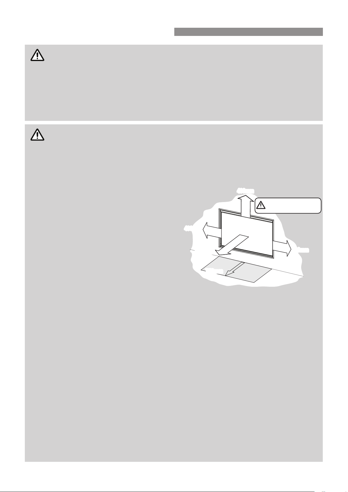
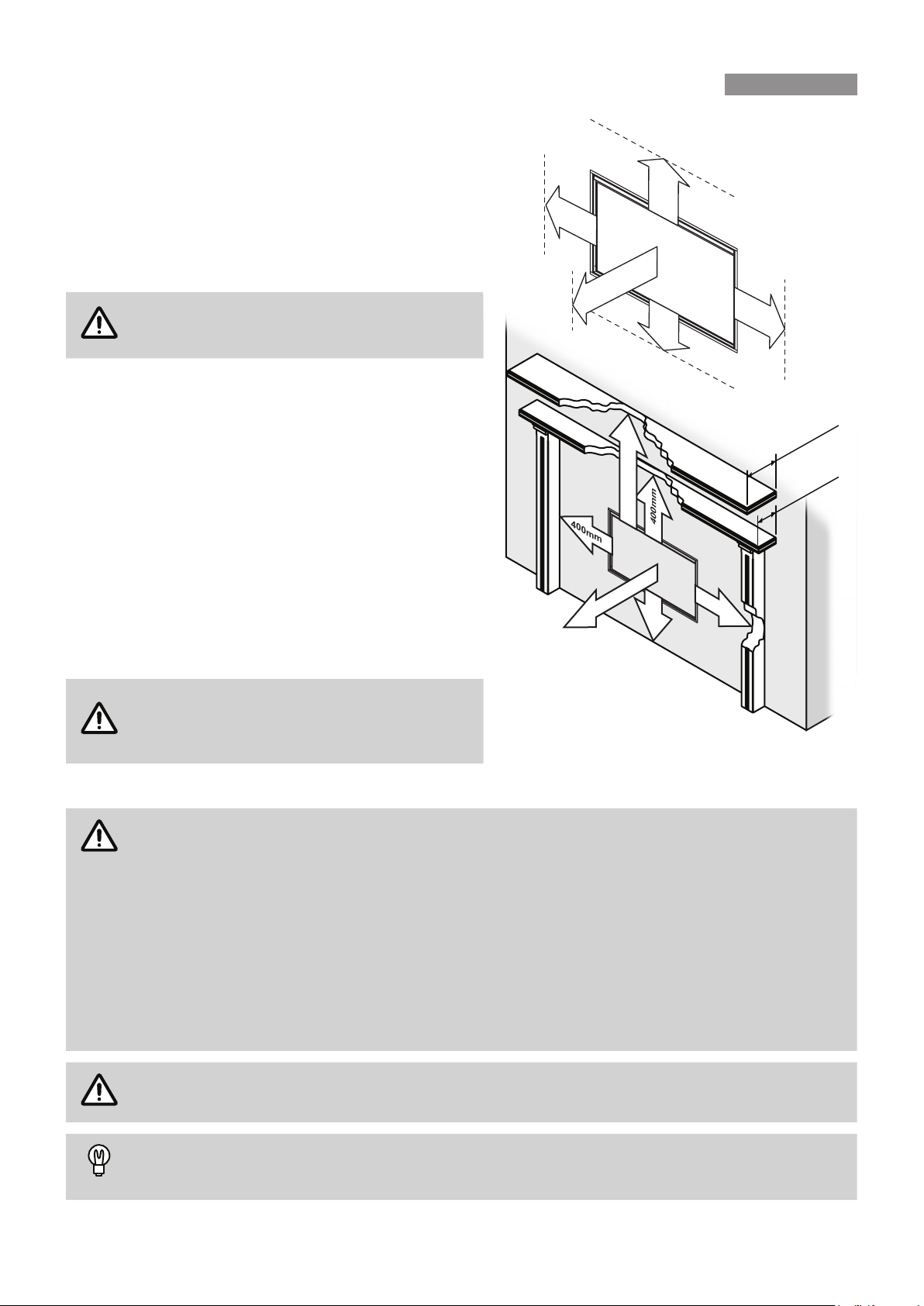
When considering installation ensure
minimum clearances as follows are adhered
to, refer Fig. 1.
Heat radiating from the front of this heater
may over time aect the appearance of
some materials used for ooring such as
carpet, vinyl, cork or timber. This eect may
be amplied if the air in the room contains
cooking vapours, candle vapours and
cigarette smoke, etc. To avoid this possibility,
it is recommended that a mat or similar
protective sheet be placed in front of the
appliance, extending at least 750 mm in front
of the dress guard. Refer to the installation
manual for mantle clearances, additional
installation information and warnings.
This appliance MUST NOT be installed where curtains or other combustible materials could
come into contact with it. In some cases curtains may need restraining.
This appliance is NOT intended for use by persons (including children) with reduced physical,
sensory or mental capabilities or lack of experience and knowledge, unless they have been given
supervision or instruction concerning use of the appliance by a person responsible for their
safety.
The appliance is NOT intended for use by young children or inrm persons without supervision.
Young children and the inrm SHOULD be supervised at all times when in the vicinity of this
heater while it is in operation.
The heater MUST NOT be located immediately below a power socket outlet.
A dedicated 230 V earthed 10 Amp power point must be used with this appliance.
Suitable ONLY for indoor installation.
DO NOT operate this appliance before leak checking hoses and gas cylinder connection.
NOT to be connected to an LP gas cylinder located indoors.
Please keep this instruction booklet in a safe place for future reference. All dimensions referred
to in these instructions are in millimetres, unless otherwise specied.
DO NOT SPRAY AEROSOLS IN THE VICINITY OF THIS APPLIANCE.
DO NOT USE OR STORE FLAMMABLE MATERIALS IN OR NEAR THIS APPLIANCE.
DO NOT PLACE ARTICLES ON OR NEAR THIS APPLIANCE.
400mm
400mm
1000mm
1000mm
750mm
750mm
Note that side and vertical
clearances are measured
from the edge of the glass.
400mm
400mm
Fig .1
Rinnai 6 RHFE0800F_1000_1500 IM
WARNINGS & IMPORTANT INFORMATION
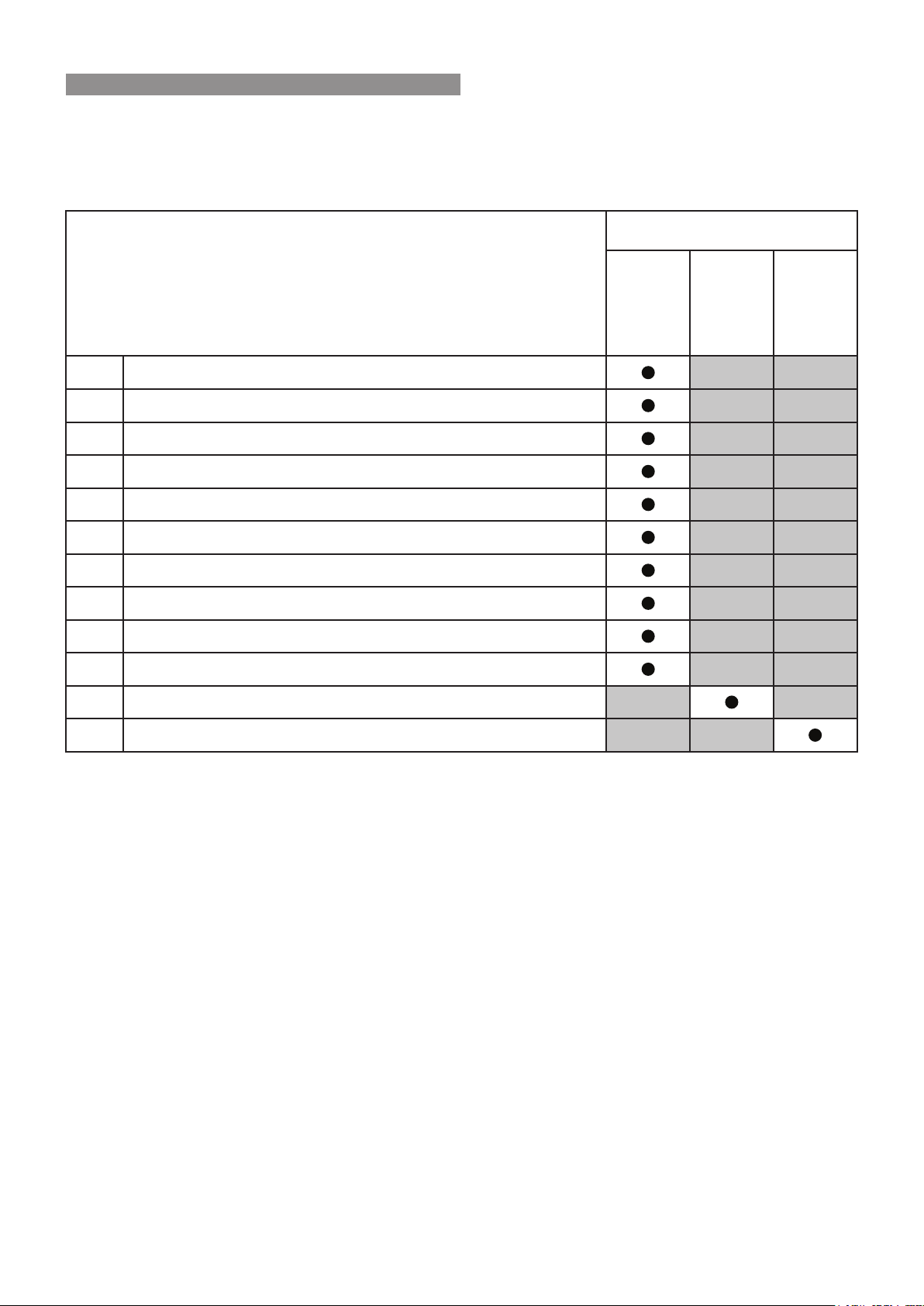
CARTON CONTENTS / ITEM CHECKLIST
The components for LS-Series heaters may be supplied in separate cartons, the following tables list which
components are in each carton. Ensure that the components listed for the installation method being installed are
present before proceeding with the installation.
CARTON CONTENTS
(1)
(2)
(3)
(4)
(5)
(6)
(7)
(8)
(9)
(10)
(11)
COMPONENTS DESCRIPTION
LS-Series Heater Engine.
Glass frame.
½” BSP Flare Adaptor and Nut (packed separately in parts plastic bag).
Remote control (batteries included)
Operation and Installation manual.
Burn media installation guide.
Colour burn media placement sheet (attached to the glass frame)
Commissioning sheet (attached in a plastic pouch inside engine)
Burner media - RHFE0800F ONLY (shipped inside engine)
Flue lock bracket and truss screws (x2)
Burn media - RHFE1000/1500 ONLY (packaged separately).
(A) (B) (C)
Engine
Burn
Media
Flue
(12)
Flue components and accessory items are ordered separately.
Rinnai 7 RHFE0800F_1000_1500 IM
NOTE
IDEA
GENERAL INSTALLATION INFORMATION
LOCATION
When positioning the heater, the main variables governing
the location are Flueing and Warm Air Distribution.
This heater MUST NOT be installed where curtains or
other combustible materials could come into contact with
it. In some cases curtains may need restraining. Refer to
"General Safety Warnings" on page 6 for additional
safety considerations.
Horizontal and vertical clearances are
measured from the edge of the burner box
glass.
Combustible mantles and surrounds can be added to
compliment the design provided that they conform to the
following clearances requirements.
The minimum clearance from the edge of the burner box
glass is 400 mm. The depth of the mantle or surround (A)
at this minimum clearance may not exceed 250 mm.
An additional 100 mm of clearance is required for every
extra 50 mm of mantle depth. The depth of the mantle
or surround (B) at 500 mm of clearance may not exceed
300 mm.
Refer to the section "Wall Lining Installation" starting on
page 27 for additional information.
Refer "Cavity Ventilation" on page 9 for cavity ventilation
details.
400mm
400mm
1000mm
1000mm
500mm
257mm
400mm
257mm
400mm
400mm
B = 300mm
A = 250mm
400mm
Combustion product spillage testing must be
conducted during appliance commissioning.
This testing may show a need for additional
xed ventilation.
TV & ORNAMENTATION WARNING
INSTALLATION OF TV OR ORNAMENTATION ABOVE THE HEATER
The installation of electrical appliances above and in the vicinity of the heater such as, but
not limited to, Plasma TV, LCD TV, Home Theatre Screens, Speakers, etc must comply with
their manufacturers' instructions. It is the responsibility of the installer/end-user to check the
installation instructions of these items and to ensure the location is suitable.
This caution also extends to, but is not limited to, ornaments such as: Paintings, Prints,
Photographs, Tapestries, Mirrors, Stued Animals, etc.
Please note the recommended clearances as per the diagram above. The temperature of the wall
surface directly above the appliance may be elevated and may discolour paint nishes or distort
vinyl wall coverings. For durability of surfaces you should contact the relevant manufacturer for
their specication.
RINNAI DOES NOT TAKE ANY RESPONSIBILITY FOR ANY DAMAGE OCCURRING TO
ANY ITEMS INSTALLED ABOVE AND IN THE VICINITY OF THE HEATER.
Use either a shelf or mantle below the TV or ornament or alternately you can construct a recess
to mount TV or ornament in. Check the manufacturers installation instructions for these items
and ensure the recess is suitable.
Rinnai 8 RHFE0800F_1000_1500 IM
FRAMING
FRAMING DIMENSIONS
Framework of the installation must conform to local building codes. Non-combustible materials need not be used.
If the appliance is elevated from the ground within the structure, a base must be constructed using suitable material
with supporting joists capable of supporting a minimum of 1.5 times the weight of the appliance.
AS/NZS 5601 “GAS INSTALLATIONS” requires that ue components be supported independently
of the appliance.
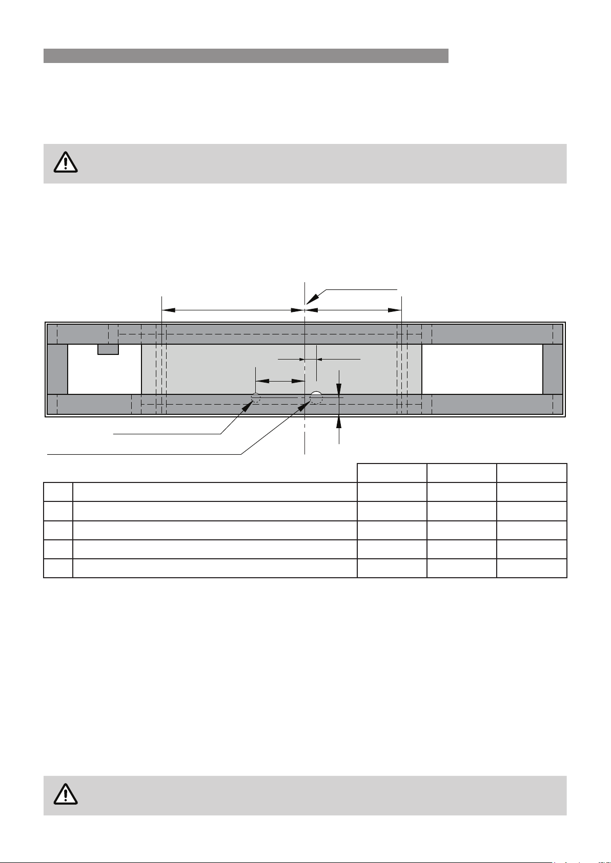
For the following framing dimensions it is important to be aware that the studs are oset—the cavity needs to be
framed based on the centreline of the glass, not the opening size.
Base Board and Cut-outs
To ensure everything lines up and ts properly, it is recommended that on the base the following dimensions are
pencilled; glass centreline, unit depth centreline, feet position, gas and room thermistor cut-outs.
Glass centreline
C D
A
B
Gas supply access
Thermistor / ambient air access Ø 40 mm
* Assumes 10mm plasterboard / All dimensions in mm RHFE0800F RHFE1000 RHFE1500
A Thermistor / ambient air access - right glass of centreline 50 50 225
B Gas supply access - left of glass centreline 220 220 220
C Support feet centres - left of glass centreline 640 740 990
D Support feet centres - right glass of centreline 360 460 710
E Gas supply / thermistor access - from front of enclosure* 77 77 77
CAVITY VENTILATION
Ventilation of at least 2000 mm² is recommended in the cavity ideally below the base of the heater engine. This
is to provide room air at ambient room temperature to the re thermistor located in the base of the heater engine.
Ventilation can be via a vent or an open toe kick at the base of the cavity, however it MUST be in the same room
and wall cavity as the heater.
Additionally the top of the cavity needs to be ventilated into the room or another space. This ventilation opening
MUST be at least 2000 mm². This opening is to prevent heat build-up within the cavity, which if left unventilated
could potentially cause damage to wall surfaces or coverings and / or cause the appliance to cut out.
E
E
Dimension
Drawing is for a top down view
assumes 10 mm plaster board
ADDITIONAL FRAMING NOTES
Plaster board is set 1 mm back from the front edge of the frame to allow for a slim edge plaster nish.
To ensure the appliance performs correctly, without rattling, the heater engine MUST be installed on a at level
support base.
Issues caused by rattling res not installed on a at level base, as detailed in this guide, will NOT
be covered by warranty.
Rinnai 9 RHFE0800F_1000_1500 IM
FRAMING
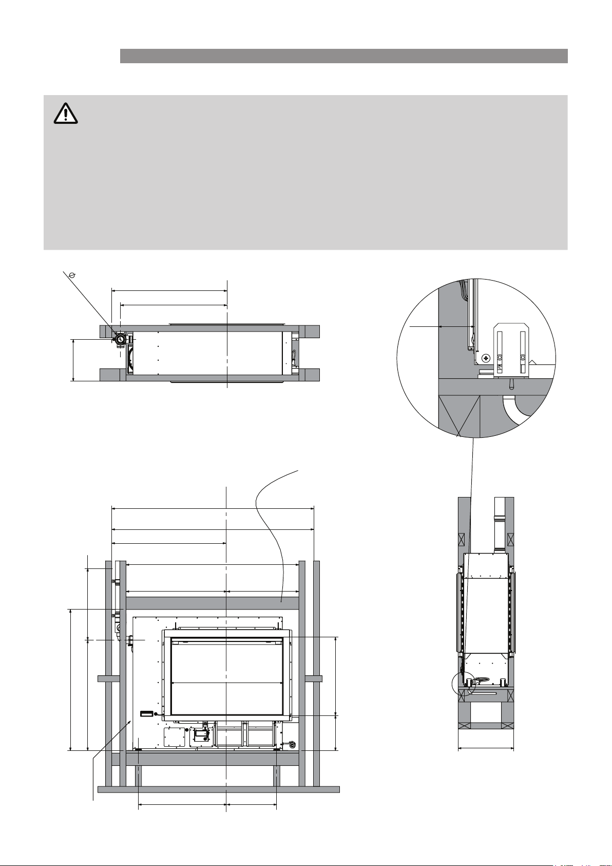
FRAMING FOR RHFE0800F
All dimensions are assuming a 10 mm plaster board.
Studs and joists are required directly below the support feet of the appliance.
Framing shown is 90 x 45 mm.
Fire platform shown is 18 mm plywood.
Allow room underneath the appliance for the gas supply to enter the re cavity (min. 100 mm).
The framing dimensions have the studs oset. This is because the cavity needs to be framed
based on the centreline of the Linear glass, NOT the opening size.
Where there is a requirement for a symmetrical installation, the cavity size will need to increase,
refer diagram below.
80**
845
770
300
Glass centreline
* Plaster board cutout for finishing trim
** Maintain 25 mm clearance
to combustibles for first 500mm
of flue
Glass centreline
1690 (for symmetrical cavity)
1365 min.
845 min.
1250 min.
Recommended that lintel
is left until fire is installed
so minimum clearances
can be maintained
39
39 mm assumes
10 mm wallboard
500 **
816 *
1020 Min
~800
Min. 50mm clearance
to top and sides
Rinnai 10 RHFE0800F_1000_1500 IM
640 360
520 Min 730 Min
566 *
257 ±5 *
403 mm assumes a 10 mm wallboard
on both sides of a double-sided unit.
415 mm is the min. for a single-sided
unit to maintain 50 mm clearance to
the back of the fire.
403
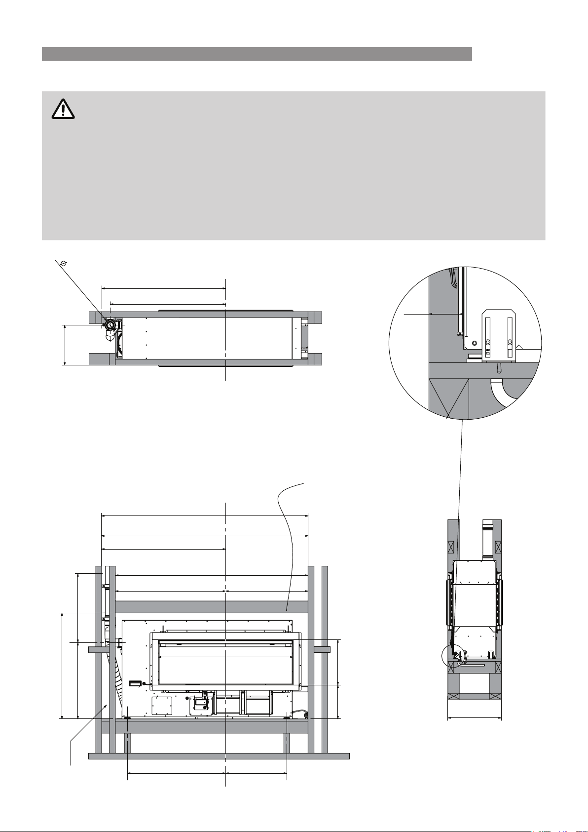
FRAMING FOR RHFE1000
All dimensions are assuming a 10 mm plaster board.
Studs and joists are required directly below the support feet of the appliance.
Framing shown is 90 x 45 mm.
Fire platform shown is 18 mm plywood.
Allow room underneath the appliance for the gas supply to enter the re cavity (min. 100 mm).
The framing dimensions have the studs oset. This is because the cavity needs to be framed
based on the centreline of the Linear glass, NOT the opening size.
Where there is a requirement for a symmetrical installation, the cavity size will need to increase,
refer diagram below.
80**
945
870
FRAMING
Glass centreline
39
300
* Plaster board cutout for finishing trim
** Maintain 25 mm clearance
to combustibles for first 500mm
of flue
Glass centreline
1890 (for symmetrical cavity)
1565 min.
945 min.
1450 min.
500 **
39 mm assumes
10 mm wallboard
Recommended that lintel
is left until fire is installed
so minimum clearances
can be maintained
620 830
1016 *
796 Min
~ 575
Min. 50mm clearance
to top and sides
Rinnai 11 RHFE0800F_1000_1500 IM
740 460
341 *
257 ±5 *
403
403 mm assumes a 10 mm wallboard
on both sides of a double-sided unit.
415 mm is the min. for a single-sided
unit to maintain 50 mm clearance to
the back of the fire.
 Loading...