

Page 1
Models:
Flametech® (RHFE0800F)
LS1000 (RHFE1000)
LS1500 (RHFE1500)
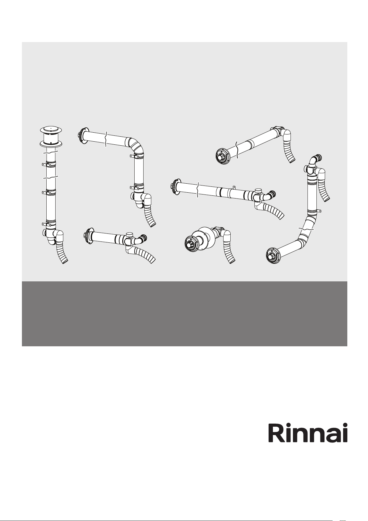
LS Series - Gas Fireplace
Flue Installation Manual
Page 2
Congratulations on the purchase of your Rinnai LS Series Gas Fireplace. We trust you will have many years of
IMPORTANT
comfort and enjoyment from your appliance.
BEFORE INSTALLING OR USING THIS APPLIANCE
Before proceeding with the operation or installation read this manual thoroughly and gain a full
understanding of the appliance, to ensure safe and correct installation and use.
USE ONLY RINNAI GENUINE PARTS
This Flue Installation Manual provides detailed requirements and instructions for Flue Systems connected to
LS Series Gas Fireplaces.
This appliance must be installed in accordance with:
• Manufacturer’s Installation Instructions
• Current AS/NZS 3000, AS/NZS 3500 & AS/NZS 5601
• Local Regulations and Municipal Building Codes
including local OH&S requirements
This appliance must be installed, maintained and removed
ONLY by an Authorised Person.
For continued safety of this appliance it must be installed
and maintained in accordance with the manufacturer’s
instructions.
This manual to suit LS - Series Heater Models:
®
Flametech
* LS1000 LS1500
RHFE0800SF * RHFE1000S RHFE1500S
RHFE0800DF * RHFE1000D RHFE1500D
®
*Incorporates Flametech
Rinnai 2 RHFE0800F_1000_1500 IM
self burning log technology.
Page 3

WARNING
INSTALLATION TABLE OF CONTENTS
Warnings & Important Information 5
Before Using or Installing This Appliance ........................................................................................................................ 5
Regulatory Information ....................................................................................................................................................... 5
Dress Guard Warnings ........................................................................................................................................................ 5
Mandatory Inspection prior to Installation ........................................................................................................................ 5
Modications. ....................................................................................................................................................................... 6
General Safety Warnings .................................................................................................................................................... 6
Flue Terminal Location ........................................................................................................................................................ 7
Other Conventions Used In This Manual ........................................................................................................................... 8
Terminal Location ................................................................................................................................................................ 8
Flue Installation Congurations 9
Flue Installation Options ..................................................................................................................................................... 9
Installation Conguration Quick Guide ........................................................................................................................... 10
Lubricating Inner Pipe Components ................................................................................................................................ 10
Installation Conguration Detailed Guide ........................................................................................................................11
Installation Conguration Component Guide ................................................................................................................. 12
Flue Exhaust & Air Inlet Connections .............................................................................................................................. 13
Direct Flue Assembly 14
Direct Extended Flue Assembly 15
Vertical Flue, External Wall 17
Vertical Flue, Internal Wall 20
Sideways Flue 21
Under Floor Flue 22
Common component Assemblies 24
Precautions for All Components ...................................................................................................................................... 24
Transition Extension Pipe ................................................................................................................................................. 24
Connecting ESPIPE900 ..................................................................................................................................................... 24
Connecting ESROOFCOWL .............................................................................................................................................. 24
Cutting - ASPDFK, LSFKIT01/02, LSFEXTKIT01, ESPIPE900 & ESROOFCOWL ......................................................... 25
Cutting Components to Achieve a Desired Length ��������������������������������������������������������������������������������������������������������� 25
Cutting Components for a Wall Penetration �������������������������������������������������������������������������������������������������������������������� 25
Wall Terminal Assembly .................................................................................................................................................... 26
On-Wall Terminal Assembly .............................................................................................................................................. 27
Connecting ESBEND ......................................................................................................................................................... 27
Contacts 28
This appliance MUST be installed, maintained and removed ONLY by an Authorised Person.
For continued safety of this appliance it MUST be installed and maintained in accordance with
the manufacturers instructions. Using ONLY Rinnai genuine parts.
Rinnai 3 RHFE0800F_1000_1500 IM
Page 4

This page is intentionally blank
Rinnai 4 RHFE0800F_1000_1500 IM
Page 5

IMPORTANT
WARNING
WARNINGS & IMPORTANT INFORMATION
BEFORE USING OR INSTALLING THIS APPLIANCE
Before proceeding with the operation or installation read this manual thoroughly and gain a full
understanding of the appliance, to ensure safe and correct use.
Failure to carefully read and follow all instructions in this manual can result in equipment
malfunction, property damage, personal injury and/or death.
DANGER: Indicates an imminently hazardous situation which, if not avoided, will result in
personal injury or death.
WARNINGS: Indicates a potentially hazardous situation which, if not avoided, could result in
personal injury or death.
CAUTIONS: Indicates a potentially hazardous situation which, if not avoided, could result in
minor or moderate injury or damage to the appliance. It may also be used to alert against unsafe
practices.
REGULATORY INFORMATION
This appliance and Flue system shall be installed in accordance with:
Manufacturer’s Installation Instructions.
Current AS/NZS 3000, AS/NZS 3500 & AS/NZS 5601.
Local Regulations and Municipal Building Codes including local OH&S requirements.
This appliance and Flue system has been certied by the Australian Gas Association. The A.G.A.
Certication Number is shown on the data plate.
This appliance and Flue system MUST be installed, maintained and removed ONLY by an
Authorised Person.
For continued safety of this appliance it MUST be installed and maintained in accordance with
the manufacturers instructions.
NOTICE TO VICTORIAN CONSUMERS
This appliance MUST be installed by a person licensed with the Victorian Building Authority.
ONLY a licensed person will have insurance protecting their workmanship.
So make sure you use a licensed person to install this appliance and ask for your Compliance
Certicate. For further information contact the Victorian Building Authority on 1300 815 127.
DRESS GUARD WARNINGS
The guard is tted to this appliance to reduce the risk of re or injury from burns and
no part of it should be permanently removed. For protection of young children or the
inrm, a secondary guard is required.
The wire dress guard supplied with this appliance MUST NOT be permanently removed as it
fulls an operational safety function. Additional dress guards including free standing types may
be used in conjunction with, but NOT replace, the dress guard supplied with this appliance.
MANDATORY INSPECTION PRIOR TO INSTALLATION
Immediately report any damage or discrepancies to the Supplier of any components. This
appliance was inspected and tested at the time of manufacture and packaging, and released for
transportation without known damage. Upon receipt, inspect the exterior for evidence of rough
handling in shipment. Ensure that the appliance is labelled correctly for the gas and electrical
supply, and/or other services it is intended to be connected to.
For safety and warranty purposes, appliances or ue components that may be damaged or
incorrect MUST NOT be installed or operated under ANY circumstances. Installation of
damaged or incorrect appliances may contravene local government regulations. Rinnai disclaims
any liability or responsibility whatsoever in relation to the installation or operation of damaged
or incorrect appliances.
Take care when opening or unpacking this appliance. Failure to do so may result in serious
injury or product failure. Check the label for the correct gas type (refer rating plate, inside the
appliance). Refer to local gas authority for conrmation of the gas type if you are in doubt.
Rinnai 5 RHFE0800F_1000_1500 IM
Page 6
400mm
400mm
WARNINGS & IMPORTANT INFORMATION
MODIFICATIONS.
DO NOT MODIFY THIS APPLIANCE, modifying from original specications may create a
dangerous situation and will void your warranty. Failure to comply with these instructions could
result in a re or explosion, which could cause serious injury, death or property damage.
DO NOT modify the electrical wiring of this appliance.
If the power cord is damaged or deteriorated then it MUST be replaced by an authorised person.
Failure to do so may result in electric shock, re, serious injury or product failure.
Improper installation, adjustments, service or maintenance can cause serious injury, death or
property damage. Such work MUST ONLY be performed by an authorised person.
GENERAL SAFETY WARNINGS
This appliance is HEAVY, during installation the use of a mechanical lifting aid is recommended,
noting that improper lifting may result in serious personal injury or damage to the appliance.
WARNING: This heater MUST NOT be used if any of the glass panels are damaged.
Flue terminal MUST always vent directly to outdoors. DO NOT extend the ue vertically or
horizontally in ways other than prescribed in this appliance manufacturer’s installation
instructions. ONLY the ue components specied by Rinnai must be used.
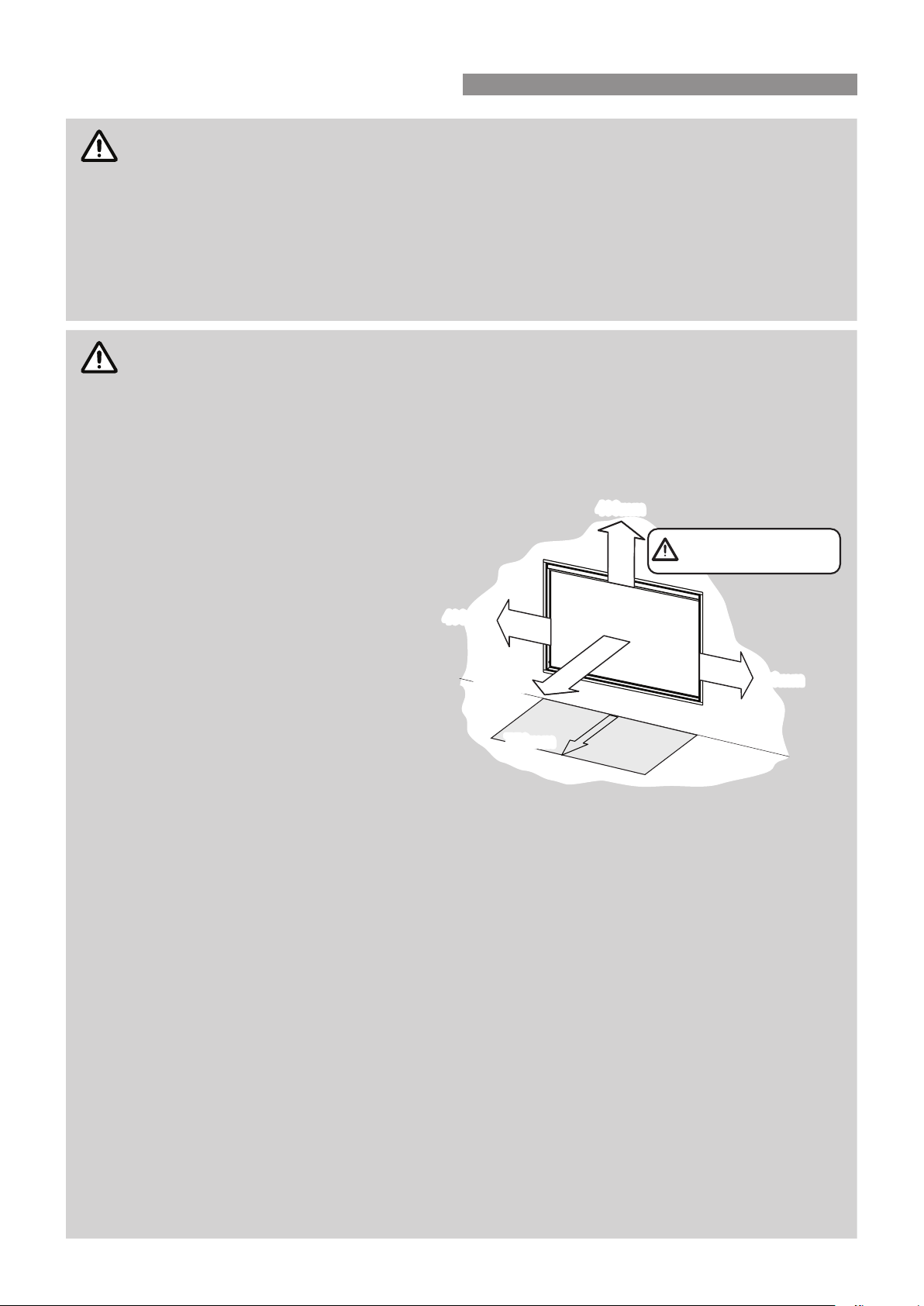
When considering installation ensure
minimum clearances as follows are
adhered to, refer Fig. 1.
Heat radiating from the front of
this heater may over time aect the
appearance of some materials used
for ooring such as carpet, vinyl, cork
or timber. This eect may be amplied
if the air in the room contains cooking
vapours, candle vapours and cigarette
smoke, etc. To avoid this possibility, it
is recommended that a mat or similar
protective sheet be placed in front of
the appliance, extending at least 750
mm in front of the dress guard. Refer
to the installation manual for mantle
clearances, additional installation
information and warnings.
This appliance MUST NOT be installed where curtains or other combustible materials could
come into contact with it. In some cases curtains may need restraining.
This appliance is NOT intended for use by persons (including children) with reduced physical,
sensory or mental capabilities or lack of experience and knowledge, unless they have been given
supervision or instruction concerning use of the appliance by a person responsible for their
safety.
The appliance is NOT intended for use by young children or inrm persons without supervision.
Young children and the inrm SHOULD be supervised at all times when in the vicinity of this
heater while it is in operation.
The heater MUST NOT be located immediately below a power socket outlet.
A dedicated 230 V earthed 10 Amp power point must be used with this appliance.
Suitable ONLY for indoor installation.
NOT to be connected to an LP gas cylinder located indoors.
Please keep this instruction booklet in a safe place for future reference. All dimensions referred
to in these instructions are in millimetres, unless otherwise specied.
DO NOT SPRAY AEROSOLS IN THE VICINITY OF THIS APPLIANCE.
DO NOT USE OR STORE FLAMMABLE MATERIALS IN OR NEAR THIS APPLIANCE.
DO NOT PLACE ARTICLES ON OR NEAR THIS APPLIANCE.
400mm
400mm
1000mm
1000mm
750mm
750mm
Note that side and vertical
clearances are measured
from the edge of the glass.
400mm
400mm
Fig .1
Rinnai 6 RHFE0800F_1000_1500 IM
Page 7
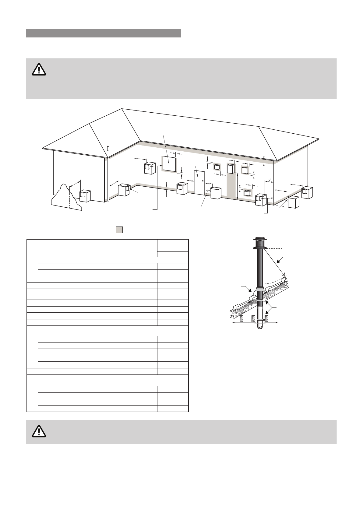
FLUE TERMINAL LOCATION
Ensure that the location of the ue terminal can comply with the requirements of AS/NZS 5601 -
Fig. 6.2 which is reproduced in part below.
AS/NZ 5601 was current at the time of printing but may have been superseded. It is the installer’s
responsibility to ensure that requirements of the current version of AS/NZS 5601 are met.
Opening into
a building
WARNINGS & IMPORTANT INFORMATION
C
T
g
T
S
LE G EN D:
I = M e c ha ni cal air in let
M = G as m ete r
P = E lec tr ic it y me ter or fuse box
S = S t r uc ture
f
T
Se e N ote 1
T = Fl ue ter minal
Z = F a n-a ss is ted a ppli ance only
Sh adin g in di c at es pro hibite d a rea for flue terminal s
Min. Clearances
metI.feR
Below eaves, balconies and other projections:
a
• Appliances up to 50 MJ/h input
• Appliances over 50 MJ/h input
From a gas meter (M) (see 5.11.5.9 for vent terminal location of regulator )
(see Table 6.6 for New Zealand requirements)
d
From an electricity meter or fuse box (P) †
e
epip lios ro epip niard a morFf
Horizontally from any building structure* = or obstruction facing a terminal
g
From any other flue terminal , cowl, or combustion air intake †
h
Horizontally from an openable window, door, non-mechanical air inlet, or any other opening into a
building with the exception of sub-floor ventilation:
• Appliances up to 150 MJ/h input *
• Appliances over 150 MJ/h input up to 200 MJ/h input *
j
• Appliances over 200 MJ/h input up to 250 MJ/h input *
• Appliances over 250 MJ/h input *
• All fan-assisted flue appliances , in the direction of discharge
Vertically below an openable window, non-mechanical air inlet, or any other opening into a
building with the exception of sub-floor ventilation:
n
• Other appliances up to 50 MJ/hr input
• Appliances over 50 MJ/h input and up to 150 MJ/h input
• Appliances over 150 MJ/h input
Natural Draught
b
Di re ction of
disch arge
(mm)
300
500
003* ecafrus rehto ro ynoclab a evoba ,dnuorg eht morFb
005* renroc lanretxe ro llaw nruter a tnorFc
1000
500
150
500
500
500
1500
1500
1500
-
0051rewolb aps a gnidulcni ,telni ria lacinahcem a morFk
051tupni rh/JM 05 ot pu sretaeh ecapS •
500
1000
1500
j
h
Door
n
j
T
e
T
P
I
h
j
Z
d
e
Se e N ote 1
a
k
k
d
M
T
T
g
g
i
iii
ii
i Minimum clearance 500mm to nearest part of roof
ii Minimum clearance 25mm to any combustible materials
iii Decktite or lead collar flashing
* - unless appliance is certified for closer installation
† - Prohibited area below electricity meter or fuse box extends to ground level.
NOTES:
1
Where dimensions c, j or k cannot be achieved an equivalent horizontal distance
measured diagonally from the nearest discharge point of the terminal to the opening
may be deemed by the Technical Regulator to comply.
2
See Clause 6.9.4 for restrictions on a flue terminal under a covered area.
3
See Figure J3 for clearances required from a flue terminal to an LP Gas cylinder.
A flue terminal is considered to be a source of ignition.
4
For appliances not addressed above acceptance should be obtained from the
Technical Regulator.
FIGURE 6.2 (in-part) MINIMUM CLEARANCES REQUIRED FOR FAN-ASSISTED FLUE TERMINALS,
ROOM-SEALED APPLIANCE TERMINALS AND OPENINGS OF OUTDOOR APPLIANCES
T
The ue terminal must be positioned away from ammable materials.
Rinnai 7 RHFE0800F_1000_1500 IM
Page 8
!
DO NOTDO NOT DO NOT DO NOT
WARNINGS & IMPORTANT INFORMATION
OTHER CONVENTIONS USED IN THIS MANUAL
The following are additional terms that may be used to highlight specic requirements during
installation steps and MUST be observed.
CLEARANCES: Where required clearances will be provided and must be observed.
FALL: Ensure that the specied 2° fall is maintained to either the terminal or the appliance as stipulated.
MEASURE: Required measurements will be provided and MUST BE observed for correct installation.
CUT: Cut as required to the specied measurements.
FINISH: Ensure that burrs and swarf are removed from all cut ends.
DISCARD: Denotes items that are not required for the specic installation.
OBSERVE CORRECT ORIENTATION: Where specied ensure that components are installed with the
correct vertical or horizontal orientation.
LUBRICATE: Use the supplied container of silicone grease to lubricate components. DO NOT use other
lubricants as these may damage the ue components.
SECURE: Where specied secure components with either installer provided or component supplied xings.
DO NOT: Failure to observe DO NOT instructions will void the warranty of an appliance and may cause injury
or death.
NOTE / IMPORTANT: Where specied secure components with either installer provided or component
supplied xings.
!
INSTALLATION STOP CAUTION: Installation stop caution notes and or warnings that MUST BE observed
for safe and correct installations.
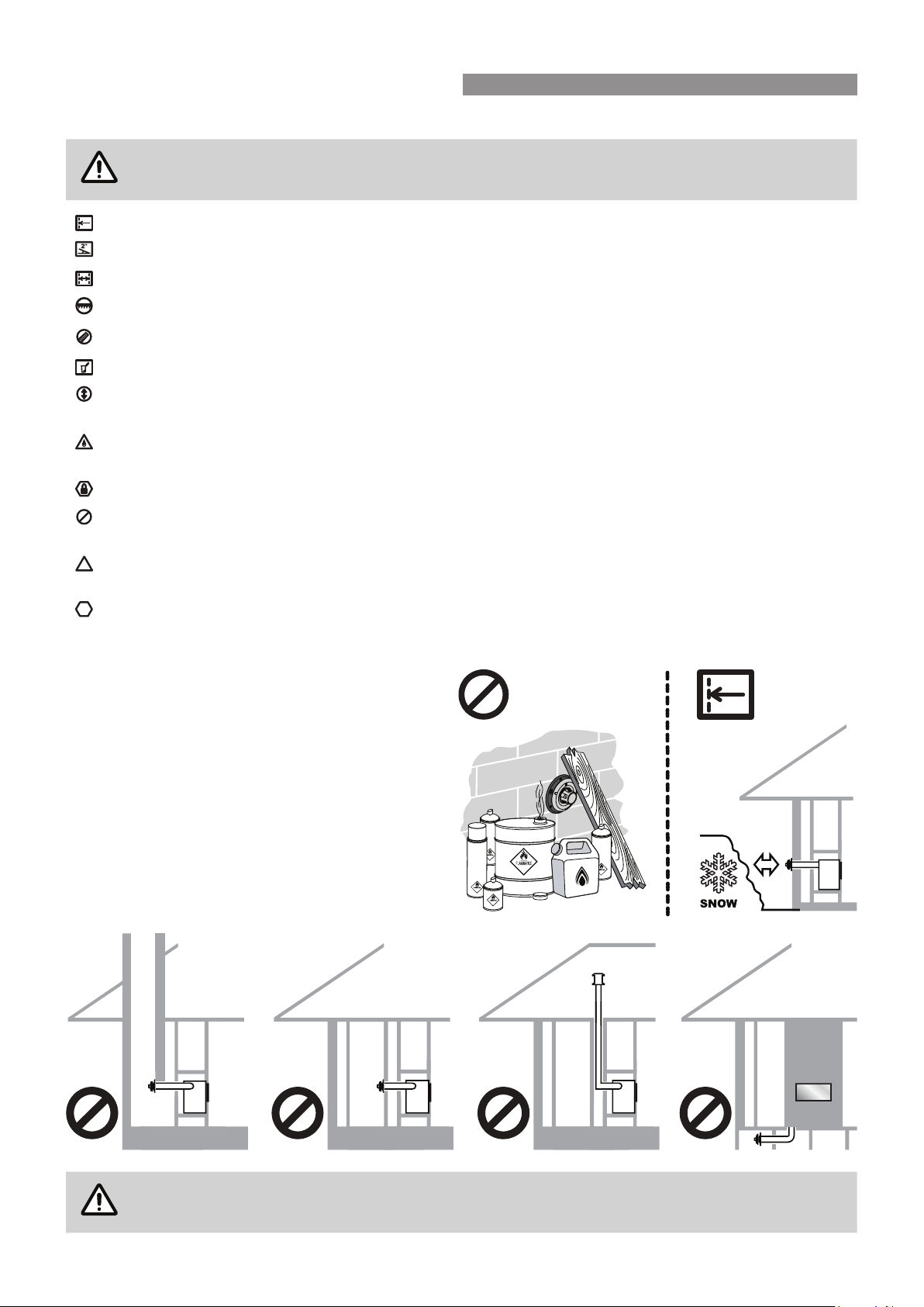
TERMINAL LOCATION
The ue terminal MUST BE positioned away from
ammable materials.
In areas subject to heavy snowfall, keep snow clear of
DO NOT
ue terminal at all times.
DO NOT ue into natural draught ues or replaces.
DO NOT ue into other rooms.
DO NOT ue into roof spaces.
DO NOT ue into under oor spaces.
DO NOT Install the heater in an unusually dusty area.
For other important information regarding the location of the heater refer to the installation and
operation manuals supplied with the appliance.
Rinnai 8 RHFE0800F_1000_1500 IM
Page 9
NOTE
NOTE
NOTE
~380 mm
445 mm
(to clear flue)
300 mm min.
(top of adaptor
to first bend)
ESROOFCOWL
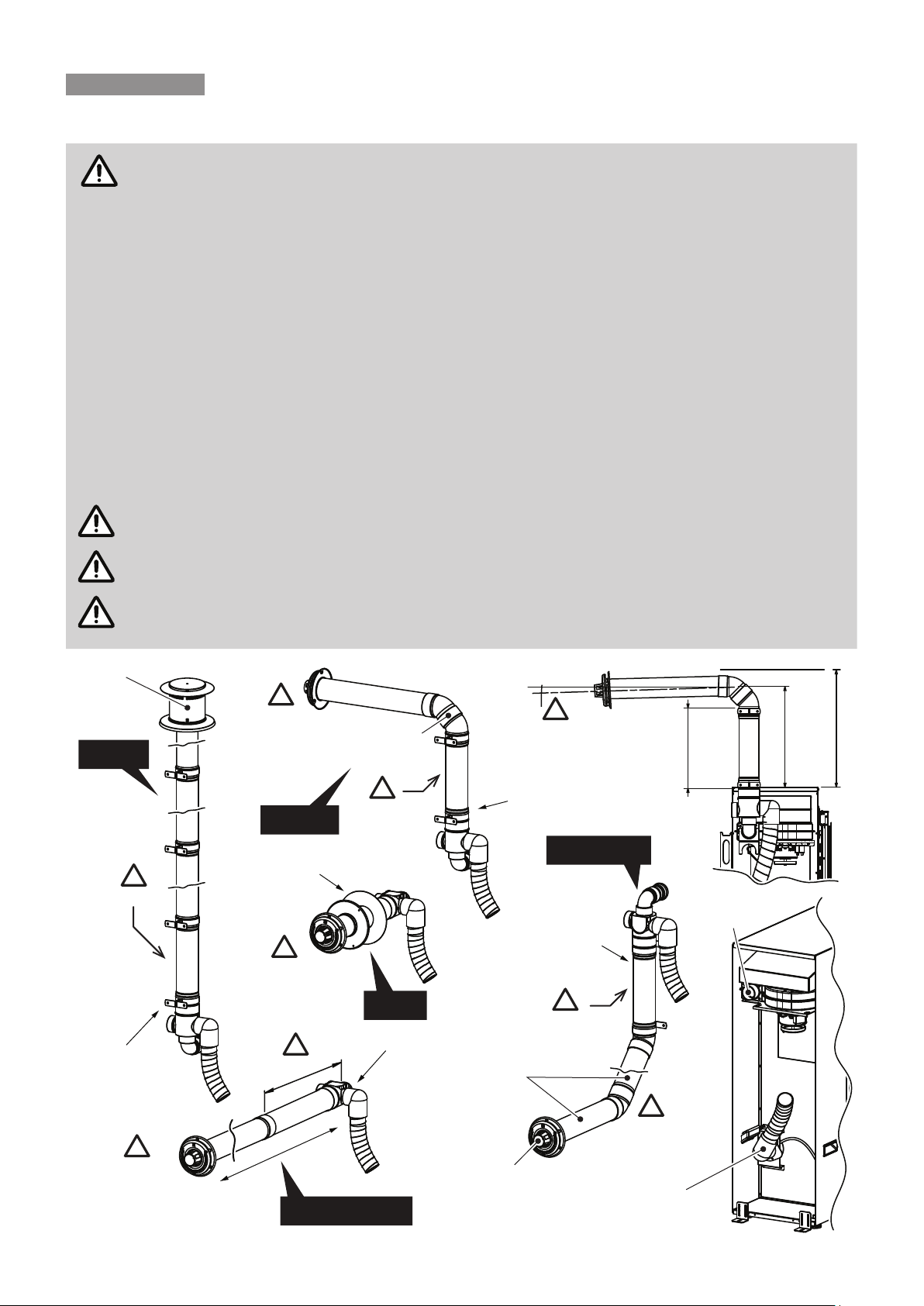
FLUE INSTALLATION CONFIGURATIONS
FLUE INSTALLATION OPTIONS
The following diagram provides an overview of the ue installation options available for LS-series
heaters.
ONLY the Rinnai ue system components specied in this reference manual MUST be used.
Components NOT specied in these manuals, whether manufactured by Rinnai or otherwise, are
NOT compatible and MUST NOT be used!
Use ONLY the supplied silicone grease when lubricating the O-rings.
Rinnai appliance warranty conditions may be voided if non Rinnai ue components are tted.
ONLY an authorised person MUST install, service and remove the Rinnai LS-series heater &
ue system.
The maximum ue length is 8.5m* and the maximum number of 90° bends is 3**.
* For every 90 ° bend, the overall ue length MUST be reduced by 1m.
** The 90° bend of the ue transition piece is NOT counted as a 90 ° bend.
LS-series heaters are factory set for "long ue installations", which is for ue runs that are 3
metres or less. Flue runs that are greater than 3 metres in length, are specied as "long ue
installations" and will require a dip switch change, refer commissioning instructions for details.
Note 1. When cutting the ue transition for joining to other components the minimum total length
is NOT to be less than 300mm!
Vertical
LSFKIT01/02
Note 2. The ue extension all aluminium component MUST be tted at this point.
Note 3. Where stipulated a Minimum 2° fall is required to ensure correct drainage of condensation
formed in the discharge ue.
!
See Note 3.
Min 2° fall towards
the appliance
Sideways
ASPDFK
45 ° bends
!
See note 2.
!
See Note 3.
Min 2° fall towards
the flue terminal
LSFKIT01/02
Under Floor
!
See note 2.
LSFKIT01/02
Flue Exhaust
Outlet
!
See Note 3.
Min 2° fall towards
the flue Terminal
!
See note 1.
Direct
ASPDFK
ESPIPE900
!
See note 2.
!
m
to 3
up
S
o
h
e
flu
t
r
Direct Extended
ESWTERM
!
See Note 3.
Min 2° fall towards
the flue Terminal
Rinnai 9 RHFE0800F_1000_1500 IM
See Note 3.
Min 2° fall towards
the flue Terminal
Air Inlet Pipe
(supplied pre fitted)
Page 10

CAUTION
FLUE INSTALLATION CONFIGURATIONS
INSTALLATION CONFIGURATION QUICK GUIDE
The information presented on this page is intended as quick reference guide to the basic
recommended installation congurations currently available for the LS-series appliances. For
alternatives to these congurations contact Rinnai.
For component congurations in greater detail and installation restrictions for these congurations
refer to the "Installation Conguration Detailed Guide" on page 11.
For full descriptions of all the available LS-series compatible ue components kits and there
contents refer to "Installation Conguration Component Guide" on page 12.
Detailed installation instructions for each of these congurations begin from page 9.
Direct / Extended External wall Internal wall Sideways Under floor
Installation
Type
Direct
Extended
Vertical
External
Wall
Vertical
Internal
Wall
Sideways LSFKIT01
Under Floor LSFKIT01 or LSFKIT02 ESPIPE900*# ESBEND**# LSFEXTKIT01 ESWTERM ESWFG
The maximum ue length is 8.5m* and the maximum number of 90° bends is 3**.
* For every 90 ° bend, the overall ue length MUST be reduced by 1m.
** The 90° bend of the ue transition piece is NOT counted as a 90 ° bend.
Transition Kit
Recommended Option
ASPDFK
or
LSFKIT01
A
B
A
ASPDFK
B
LSFKIT01
or
LSFKIT02
A
B
A
B
Common Additional Components
ESWFG
ESPIPE900*# LSFEXTKIT01 ESWFG
ESPIPE900*# ESBEND**# ESROOFCOWL
ESPIPE900*# ESBEND**# LSFEXTKIT01 ESWTKIT
ESPIPE900*#
ESPIPE900*# ESBEND**#
ESPIPE900*# ESWTERM ESWFG
ESPIPE900*# ESBEND**# ESWTERM ESWFG
# Order extra components as required
LUBRICATING INNER PIPE COMPONENTS
The inner ue pipe joints are sealed with an "O" ring seal.
To ease assembly, a small container of silicone grease is provided with the Direct Flue Kit (ASPDFK) and the Flue
Adaptation Kit (ASPKIT03). Use this silicone grease to lubricate the "O" ring on the inner pipes prior to assembly.
To obtain the desired amount of protrusion for termination, the ESPIPE900 may need to cut. Do
this in accordance with "Connecting ESPIPE900" on page 24
Rinnai 10 RHFE0800F_1000_1500 IM
Page 11

IN-WALL
Note 1. When cutting the flue transition for joining to other components the minimum total length is NOT to be less than 300mm!
FLUE INSTALLATION CONFIGURATIONS
INSTALLATION CONFIGURATION DETAILED GUIDE
Note 2. The flue extension all aluminium component MUST be fitted at this point.
IMPORTANT
Note 3. Where stipulated a Minimum 2° fall is required to ensure correct drainage of condensation formed in the discharge flue.
The maximum flu length is 8.5m and the maximum number of 90° bends is 3, however for every 90 ° bend, overall flue length MUST be
reduced by 1m (For LS-series heaters the bend of the transition piece is NOT counted as one of these 3 90 ° bends).
Cut to correct
length & discard
See note 1.
Cut to correct
length & discard
!
!
See Note 3.
Min 2° fall towards
the flue Terminal
• DIRECT
DIRECT
• DIRECT EXTENDED
Cut to correct
length & discard
!
See note 1.
UNDER FLOOR
!
See Note 3.
Min 2° fall towards
the flue Terminal
DIRECT EXTENDED
!
See note 2.
!
A
See note 2.
• EXTERNAL WALL
• IN-WALL
!
See note 2.
!
See Note 3.
Min 2° fall towards
the flue Terminal
SIDEWAYS
• UNDER FLOOR
A
• SIDEWAYS
!
Cut to correct
length & discard
!
See Note 3.
Min 2° fall towards
the flue Terminal
Rinnai 11 RHFE0800F_1000_1500 IM
!
See Note 3.
Min 2° fall towards
the flue Terminal
A
See Note 3.
Min 2° fall towards
the appliance
EXTERNAL WALL
!
See note 1.
Page 12

FLUE INSTALLATION CONFIGURATIONS
INSTALLATION CONFIGURATION COMPONENT GUIDE
ASPDFK
(Direct Flue Kit for Rinnai Flamefires)
Internal Wall Plate
External Wall Plate
Flue Terminal
Silicone Grease
Flue Transition
22mm
x6
Mounting/Securing Screws
ESBEND
Co-ax Bends & Pipe Locating
Spacer x2
7mm
x2
BOTH spacers are
required for all offset
and extended offset
installations!
ESPLATE
Mounting/Securing Screws
(This manual also included)
External Wall Plate
22mmx37mm
x2
LSFKIT01
(Flue Adaption Kit
for Rinnai LS-series heaters)
Transition Extension Pipe
Spacer
Flue Transition
Wall Clip
Silicone Grease
(This manual also included)
LSFEXTKIT01
Transition Extension Pipe
LSFKIT02
(Extended Flue Adaption Kit
for Rinnai LS-series heaters)
Co-ax Vertical Terminal
3x Co-ax Pipe
Co-ax Bends & Pipe
Locating Spacers x 2
Transition Extension Pipe
Spacer
ESPIPE900
Co-ax
Pipe
ESROOFCOWL
Co-ax
Vertical
Terminal
Spacer
Silicone Grease
ESWTERM
External Wall Plate
Flue Terminal
22mm
x6
Mounting/Securing Screws
ESWTKIT
(Wall Terminal Kit)
Wall Clip
7mm
x2
External Wall Plate
Extension Pipe
Silicone Grease x2
(This manual also included)
ESWFG
Wall Clips x5
Flue Guard
Wall
Clip
Wall
Clip
22mm
x3
Mounting/Securing Screws
7mm
x2
Pipe Spacer
Flue Outlet Grill
Rinnai 12 RHFE0800F_1000_1500 IM
Page 13

Flue exhaust
Air inlet hose
(shown installed)
FLUE INSTALLATION CONFIGURATIONS
FLUE EXHAUST & AIR INLET CONNECTIONS
The following steps in the installation are critical. If the connections are not secured correctly,
then products of combustion could disperse into living areas.
1. Connect the ue terminal exhaust connection to the ue exhaust outlet, and secure in place (two screws) with
the ue locking bracket (supplied in the accessories plastic bag with the remote control).
2. Secure the ue transition to the framing using a wall clip (supplied with LSFKIT01/02 or ASPDFK).
3. Attach the air intake hose to the large air inlet connection on the ue transition (LSFKIT01/02 or ASPDFK)
and secure in place with the supplied cable tie (also supplied), noting that the other end of the air inlet hose
is already pre-installed to the appliance.
4. Ensure that the rubber cap remains secured in place on the unused (small) air inlet connection.
locking bracket
Flue exhaust outlet
Flue exhaust
locking bracket
(shown installed)
Air inlet hose
(This end is to be
fitted to LSFKIT01/02
or ASPDFX)
Air inlet hose
(This end is supplied
pre-fitted to the appliance)
(Extension piece not shown)
ASPDFK
Air inlet hose
Flue exhaust
locking bracket
LSFKIT01/02
Flue exhaust
connection
Large air inlet
connection
Flue exhaust
connection
Flue exhaust
locking bracket
(shown installed)
Air inlet hose
(This end is supplied pre fitted to the appliance)
Flue exhaust
connection
Small air inlet connection
(Rubber cap MUST remain in place)
Rinnai 13 RHFE0800F_1000_1500 IM
Page 14

ASPDFK
CAUTION
NOTE
ASPDFK
See note 1.
!
Direct Extended
Min 2° fall towards
the flue Terminal
Air Inlet Pipe
(supplied pre fitted)
Flue Exhaust
Outlet
ESPIPE900
LSFKIT01
DIRECT FLUE ASSEMBLY
Follow the engine and ue installation instructions detailed
in the Installation manual provided with appliance.
The Direct ue kit (ASPDFK) is suitable for walls up to
385mm thick. ASPDFK can be cut to length to suit wall
thickness’s less than 385mm thick.
For wall thickness’s greater than 385mm Co-axial Pipe(s)
(ESPIPE900) can be fastened onto ASPDFK to extend
the ue length. Refer to the section "Direct Extended Flue
Assembly" on page 15 for details.
With heater engine installed into the support framing:
1. Create the wall penetration(s).
The minimum diameter required for wall
the penetration for a DIRECT ue installation is
80mm to non-combustible surfaces such as brick
and 100mm to combustible surfaces such as plaster.
Allow for a continuous 2° fall from the heater
connection point to the wall terminal.
2. Slide the internal wall plate over the terminal end of
the ASPDFK pipe until it is nested on the raised ring
of the ue transition.
3. Pass the ASPDFK through the internal wall
penetration.
Min 2° fall towards
the flue Terminal
LSFKIT01
Flue Exhaust
Outlet
Direct
Air Inlet Pipe
(supplied pre fitted)
4. Make the heater exhaust and combustion air hose
5. Slide the internal wall plate so that it is ush with the
6. Create the wall terminal in accordance with "Wall
7. Refer to Installation Manual provided with appliance
connections.
Air hose and heater exhaust connections
MUST be made and checked in accordance
with "Flue Exhaust & Air Inlet Connections"
on page 13. Improper connections may
result in dangerous situations, for example,
the dispersion of combustion products in
the space being heated and living areas.
wall.
Terminal Assembly" on page 26
to nalise installation and commissioning of the
heater.
Use ONLY the supplied silicone based
“O Ring” seal lubricant. DO NOT use
petroleum based lubricants such as
petroleum jelly. The use of petroleum jelly,
Vaseline® or similar petroleum based
lubricants will cause rapid deterioration of
the ‘O Ring’ seals.
For non-condensing heaters a 2° fall of the
ue away from the heater helps prevent
rainwater or sprinkler water etc from entering
the ue system.
Interior wall
1
Max’ wall thickness 385mm
Min’ required protrusion 15mm
2
Internal wall plate, outer face
Exterior wall
3
Rinnai 14 RHFE0800F_1000_1500 IM
Page 15

CAUTION
CAUTION
NOTE
Flue Exhaust
DIRECT EXTENDED FLUE ASSEMBLY
Follow the engine and ue installation instructions detailed
in the Installation manual provided with appliance.
To create a DIRECT EXTENDED FLUE, Co-axial Pipe(s)
(ESPIPE900) can be fastened onto ASPDFK.
Use ONLY the supplied silicone based
“O Ring” seal lubricant. DO NOT use
petroleum based lubricants such as
petroleum jelly. The use of petroleum jelly,
Vaseline® or similar petroleum based
lubricants will cause rapid deterioration of
the ‘O Ring’ seals.
ONLY use PVC cement between
externally located joints of PVC pipes to
secure and seal these joints against ingress
of dust and water.
ONLY use non-acidic silicone sealant
between externally located joints of PVC ue
pipe and any mating aluminium components
(such as the condensate trap) to secure and
seal these joints against ingress of dust and
water. Silicone containing acetic acid,
(characteristically having a vinegar odour),
as the curing agent or other acids may cause
corrosion of aluminium components and
MUST NOT be used.
Secure the vertical ue sections to the
wall using the clips provided to prevent
accidental dislodgement.
NOTE 1. When cutting the ue transition for
joining to other components the minimum
total length is NOT to be less than 300mm!
ESPIPE900
Min 2° fall towards
the flue Terminal
LSFKIT01
Interior wall
1
Min’ required protrusion 50mm
!
See note 1.
ASPDFK
Direct Extended
Air Inlet Pipe
(supplied pre fitted)
Outlet
With heater engine installed into the support framing.
1. Create the wall penetration(s).
The minimum diameter required for wall
the penetration for a DIRECT ue installation is
80mm to non-combustible surfaces such as brick
and 100mm to combustible surfaces such as plaster.
Allow for a continuous 2° fall from the heater
connection point to the wall terminal.
2. Join ESPIPE900 to ASPDFK. Fit additional lengths
of ESPIPE900 as required. Slide the internal wall
plate over the terminal end of the ASPDFK pipe until
it is nested on the raised ring of the ue transition.
Internally located joints between ASPDFK
and ESPIPE900 and any additional
ESPIPE900 lengths MUST be secured by a
pop rivet or screw through the outer Co-axial
pipes to prevent accidental or erroneous
dislodgement.
ASPDFK and ESPIPE900 DO NOT require
cutting to be joined.
Internal wall plate, outer face
2
Exterior wall
3
Rinnai 15 RHFE0800F_1000_1500 IM
Page 16

CAUTION
DIRECT EXTENDED FLUE ASSEMBLY
4. Pass the ASPDFK through the internal wall perforation.
5. Make the heater exhaust and combustion air hose connections.
Air hose and heater exhaust connections MUST be made and checked in accordance with "Flue
Exhaust & Air Inlet Connections" on page 13. Improper connections may result in dangerous
situations, for example, the dispersion of combustion products in the space being heated.
6. Slide the internal wall plate so that it is ush with the wall.
7. Create the wall terminal in accordance with "Wall Terminal Assembly" on page 26
To obtain the desired amount of protrusion for termination, the ESPIPE900 may need to cut. Do
this in accordance with "Connecting ESPIPE900" on page 24
8. Refer to Installation Manual provided with appliance to nalise installation and commissioning of the heater.
Rinnai 16 RHFE0800F_1000_1500 IM
Page 17

CAUTION
NOTE
NOTE
VERTICAL FLUE, EXTERNAL WALL
Follow the engine and ue installation instructions detailed
in the Installation manual provided with appliance.
The creation of the horizontal section of ue installation is
the same as creating a DIRECT or DIRECT EXTENDED
ue installations with the following exceptions:
The direction of horizontal fall of the ue pipe is
reversed. For Wall External ue installations, a 2° fall is
required from the wall penetration towards the heater.
An ESBEND rather than the ESWTERM ue terminal is
tted at the end of the horizontal ue run.
The maximum ue length is 8.5m* and the
maximum number of 90° bends is 3**.
* For every 90 ° bend, the overall ue length
MUST be reduced by 1m.
** The 90° bend of the ue transition piece is
NOT counted as a 90 ° bend.
Note 1. When cutting the ue transition for
joining to other components the minimum
total length is NOT to be less than 300mm!
Possible kits and components required for creating
VERTICAL EXTERNAL WALL installations:
ESPIPE900
Min 2° fall towards
the appliance
ASPDFK
!
See note 1.
Direct Extended
Air Inlet Pipe
(supplied pre fitted)
Flue Exhaust
Outlet
ASPDFK (LSFKIT01/02 may also be used)
A
ESPLATE#
B
ESBEND#
C
LSFEXTKIT01# (require for change of connection
D
direction when terminating with an ESROOFCOWL)
ESPIPE900#
E
ESPLATE#
F
ESROOFCOWL or ESWTKIT
G
# Available separately or as part of kit see "Installation
Conguration Component Guide" on page 12 for kit
component contents.
1. Follow the installation method for a "Direct Flue
Assembly" on page 14 or for a "Direct Extended
Flue Assembly" on page 15 to the completion of
step 4.
If required, components of LSFKIT01 and
LSFKIT02 may be utilised as an alternative
to using the ASPDFK kit to create a DIRECT
or DIRECT EXTENDED installation to reach
the point of the external wall penetration.
G
F
E
D
When using LSFKIT01 and LSFKIT02 a
sideways conguration will be required
to reach the point of the external wall
penetration.
For details on how to create a sideways
ue conguration refer to “CREATING A
“SIDEWAYS” FLUE INSTALLATION” on page
14.
Rinnai 17 RHFE0800F_1000_1500 IM
C
B
A
Page 18

CAUTION
CAUTION
VERTICAL FLUE, EXTERNAL WALL
2. Slide the external wall plate over the outer pipe
protruding through the exterior wall. Ensure a 2°
fall of the horizontal section of ue pipe towards the
appliance as required.
!
Once the external wall plate is in the correct
position secure it to the wall using the three 22mm
screws into the holes provided. The wall plate is then
secured to the outer pipe of the ue protrusion using
the two horizontal holes and the two 7mm screws
provided.
22mm x 3
7mm x 2
2
3.
Cut the ue pipe end protruding through the
exterior wall in accordance with "Connecting
ESPIPE900" on page 24.
Use ONLY the supplied silicone based
“O Ring” seal lubricant. DO NOT use
petroleum based lubricants such as
petroleum jelly. The use of petroleum jelly,
Vaseline® or similar petroleum based
lubricants will cause rapid deterioration of
the ‘O Ring’ seals.
ONLY use PVC cement between
externally located joints of PVC pipes to
secure and seal these joints against ingress
of dust and water.
ONLY use non-acidic silicone sealant
between externally located joints of PVC ue
pipe and any mating aluminium components
(such as the condensate trap) to secure and
seal these joints against ingress of dust and
water. Silicone containing acetic acid,
(characteristically having a vinegar odour),
as the curing agent or other acids may cause
corrosion of aluminium components and
MUST NOT be used.
3
4
Min’ require
For installations being terminated
!
with ESROOFCOWL !
d protrusion 50mm
!
Secure the vertical ue sections to the
wall using the clips provided to prevent
accidental dislodgement.
4. Now prepare the vertical section of the ue system by assembling, connecting and securing ESBEND,
ESCONDK and subsequent ESPIPE900 lengths as required in accordance with the relevant sections
under "Connecting ESBEND" on page 27, “COMPONENT ASSEMBLY & CONNECTION ~ TRANSITION
EXTENSION PIPE (LSFEXTKIT01)” refer to page 24 and “COMPONENT ASSEMBLY & CONNECTION ~
ESPIPE900” refer to page 24.
!
For installations being terminated with ESROOFCOWL a Transition Extension Pipe
(LSFEXTKIT01)* will need to be installed at this point. This is required to enable the change of
connection direction necessary when tting the ESROOFCOWL.
* All ue installations that use LSFKIT01/02 MUST be tted with Transition Extension Pipe.
5. If a vertical roof terminal is used cut in accordance with “CUTTING ~ ASPDFK, LSFKIT01/02, ESPIPE900 &
ESROOFCOWL FLUE PIPES” on page 23 and assemble and connect in accordance with “All “External Wall”,
Rinnai 18 RHFE0800F_1000_1500 IM
Page 19

VERTICAL FLUE, EXTERNAL WALL
“Internal Wall”, “Sideways” and “Under Floor” ue installations MUST be tted with Transition Extension Pipe
when using LSFKIT01/02.” on page 23.
If a horizontal terminal is used cut in accordance with “CUTTING ~ ASPDFK, LSFKIT01/02, ESPIPE900 &
ESROOFCOWL FLUE PIPES” on page 23 and assemble and connect in accordance with “ASSEMBLING
AN ON-WALL TERMINAL ~ ESWTKIT, ESBEND & ESPIPE900” on page 23.
6. Refer to Installation Manual provided with appliance to nalise installation and commissioning of the heater.
Rinnai 19 RHFE0800F_1000_1500 IM
Page 20

CAUTION
NOTE
CAUTION
VERTICAL FLUE, INTERNAL WALL
Follow the engine installation instructions detailed in the
Installation manual provided with appliance.
The vertical ue installation is installed against an internal
wall within a false re place or other suitable cavity and is
run vertically upwards to the termination point.
When considering the location of the heater due care
MUST be taken to ensure that the ue path in the roof
space are free of obstructions such as studs, noggins,
joists, braces, and electricals etc.
The maximum ue length is 8.5m* and the
maximum number of 90° bends is 3**.
* For every 90 ° bend, the overall ue length
MUST be reduced by 1m.
** The 90° bend of the ue transition piece is
NOT counted as a 90 ° bend.
Note 2. The all aluminium ue extension
component MUST be tted at this point.
With heater engine installed into the support framing
complete the following:
1. Assemble the components of the Flue Adaptation Kit
(LSFKIT01/02), by joining the ue transition and the
transition extension pipe components together.
Flue Exhaust
Outlet
ESROOFCOWL
Vertical
!
See note 2.
LSFKIT01/02
Air Inlet Pipe
(supplied pre fitted)
1
The transition extension pipe connections are the
same at each end, so either end may be connected.
All ue installations that use LSFKIT01/02 MUST be tted with Transition Extension Pipe.
Use ONLY the supplied silicone based “O Ring” seal lubricant. DO NOT use petroleum
based lubricants such as petroleum jelly. The use of petroleum jelly, Vaseline® or similar petroleum
based lubricants will cause rapid deterioration of the ‘O Ring’ seals.
The join between the ue transition and ue transition extension MUST be secured by a pop
rivet or screw through the outer Co-axial pipes to prevent accidental or erroneous dislodgement.
The assembled LSFKIT01/02 is to be clipped to the structure using the stand o clips supplied or
other suitable method.
LSFKIT01/02 components and ESPIPE900 DO NOT require cutting to be joined.
2. Make the heater exhaust and combustion air hose connections in accordance with"Flue Exhaust & Air Inlet
Connections" on page 13.
Air hose and heater exhaust connections MUST be made and checked in accordance with "Flue
Exhaust & Air Inlet Connections" on page 13. Improper connections may result in dangerous
situations, for example, the dispersion of combustion products in the space being heated.
3. Create the ceiling and or wall penetration(s).
The minimum diameter required for wall the penetration for a Vertical ue installation is 80mm to non-
combustible surfaces such as brick and 100mm to combustible surfaces such as plaster.
4. Fit lengths of ESPIPE900 to LSFKIT01/02 in accordance with “COMPONENT ASSEMBLY & CONNECTION
~ ESPIPE900” on page 24. Determine the location of roof and or ceiling penetration points. To avoid
obstructions in the ue path a horizontal oset can be created using ESBEND.
5. Create a vertical roof terminal in accordance with “CUTTING ~ ASPDFK, LSFKIT01/02, ESPIPE900 &
ESROOFCOWL FLUE PIPES” on page 23.
6. Refer to Installation Manual provided with appliance to nalise installation and commissioning of the heater.
Rinnai 20 RHFE0800F_1000_1500 IM
Page 21

CAUTION
NOTE
CAUTION
SIDEWAYS FLUE
Follow the engine installation instructions detailed in the
Installation manual provided with appliance.
The SIDEWAYS ue installation will instead of terminating
through the ceiling run sideways to the left or right of the
cavity and terminate through an external wall.
A 2° fall
is required from the wall penetration towards the heater.
When considering the location of the heater due care
MUST be taken to ensure that the ue path is free of
obstructions such as studs, noggins, joists, braces, and
electricals etc.
The maximum ue length is 8.5m* and the
maximum number of 90° bends is 3**.
* For every 90 ° bend, the overall ue
maximum allowable length MUST be
reduced by 1m.
** The 90° bend of the ue transition piece is
NOT counted as a 90 ° bend.
Note 2. The ue all aluminium extension
component MUST be tted at this point.
With heater engine installed into the support framing.
1. Assemble the components of the Flue Adaptation Kit
(LSFKIT01/02), by joining the ue transition and the
transition extension pipe components together.
!
Min 2° fall towards
the terminal
See note 2.
LSFKIT01/02
Sideways
45 ° bends
!
Air Inlet Pipe
(supplied pre fitted)
1
Flue Exhaust
Outlet
The transition extension pipe connections are the
same at each end, so either end may be connected.
All ue installations that use LSFKIT01/02 MUST be tted with Transition Extension Pipe.
Use ONLY the supplied silicone based “O Ring” seal lubricant. DO NOT use petroleum
based lubricants such as petroleum jelly. The use of petroleum jelly, Vaseline® or similar petroleum
based lubricants will cause rapid deterioration of the ‘O Ring’ seals.
The join between the ue transition and ue transition extension MUST be secured by a pop
rivet or screw through the outer Co-axial pipes to prevent accidental or erroneous dislodgement.
The assembled LSFKIT01/02 is to be clipped to the structure using the stand o clips supplied or
other suitable method.
LSFKIT01/02 components and ESPIPE900 DO NOT require cutting to be joined.
2. Make the heater exhaust and combustion air hose connections in accordance with "Flue Exhaust & Air Inlet
Connections" on page 13.
Air hose and heater exhaust connections MUST be made and checked in accordance with "Flue
Exhaust & Air Inlet Connections" on page 13. Improper connections may result in dangerous
situations, for example, the dispersion of combustion products in the space being heated.
3. Create the wall penetration(s).
The minimum diameter required for wall the penetration for a DIRECT ue installation is 80mm to non-
combustible surfaces such as brick and 100mm to combustible surfaces such as plaster.
Allow for a continuous 2° fall from the heater connection point towards the heater.
4. Fit combinations of ESPIPE900 and ESBEND to LSFKIT01/02 as required to reach the termination point in
accordance with “COMPONENT ASSEMBLY & CONNECTION ~ ESPIPE900” on page 24 and “COMPONENT
ASSEMBLY & CONNECTION ~ ESBEND” on page 24.
5. Create the wall terminal in accordance with “ASSEMBLING WALL TERMINAL ~ ASPDFK & ESPIPE900” on
page 24.
6. Refer to Installation Manual provided with appliance to nalise installation and commissioning of the heater.
Rinnai 21 RHFE0800F_1000_1500 IM
Page 22

CAUTION
NOTE
CAUTION
4
Interior wall
Internal
wall plate
Stand off clip
5
Interior wall
Interior wall
Floor Penetration
location
3
UNDER FLOOR FLUE
Follow the engine installation instructions detailed in the
Installation manual provided with appliance.
The UNDER FLOOR FLUE ue installation allows for a
Flue Adaptation Kit (LSFKIT01/02) to face downwards
and the ue to be run vertically though a hole in the oor,
and then horizontally to a suitable location outside.
When considering the location of the heater due care
MUST be taken to ensure that the ue path under the
oor is free of obstructions such as studs, noggins, joists,
braces, and electricals etc.
The maximum ue length is 8.5m* and the
maximum number of 90° bends is 3**.
* For every 90 ° bend, the overall ue length
MUST be reduced by 1m.
** The 90° bend of the ue transition piece is
NOT counted as a 90 ° bend.
Note 2. The ue all aluminium extension
component MUST be tted at this point.
With heater engine installed into the support framing.
1. Assemble the components of the Flue Adaptation Kit
(LSFKIT01/02), by joining the ue transition and the
transition extension pipe components together.
The transition extension pipe connections are the
same at each end, so either end may be connected
Under Floor
LSFKIT01/02
See note 2.
ESPIPE900
ESWTERM
1
!
!
See Note 3.
Min 2° fall towards
the flue Terminal
Air Inlet Pipe
(supplied pre fitted)
Flue Exhaust
Outlet
Interior wall
2
All ue installations that use LSFKIT01/02 MUST be tted with Transition Extension Pipe.
Use ONLY the supplied silicone based “O Ring” seal lubricant. DO NOT use petroleum
based lubricants such as petroleum jelly. The use of petroleum jelly, Vaseline® or similar petroleum
based lubricants will cause rapid deterioration of the ‘O Ring’ seals.
Use ONLY the supplied silicone based “O Ring” seal lubricant. DO NOT use petroleum
based lubricants such as petroleum jelly. The use of petroleum jelly, Vaseline® or similar petroleum
based lubricants will cause rapid deterioration of the ‘O Ring’ seals.
The joint between the ue transition and ue transition extension MUST be secured by a pop
rivet or screw through the outer Co-axial pipes to prevent accidental or erroneous dislodgement.
The assembled LSFKIT01/02 is to be clipped to the structure using the stand o clips supplied or
other suitable method.
LSFKIT01/02 components and ESPIPE900 DO NOT require cutting to be joined.
2. Make the heater exhaust and combustion air hose connections in accordance with"Flue Exhaust & Air Inlet
Connections" on page 13.
Then secure LSFKIT01/02 in place with the provided wall bracket.
Air hose and heater exhaust connections MUST be made and checked in accordance with "Flue
Exhaust & Air Inlet Connections" on page 13. Improper connections may result in dangerous
situations, for example, the dispersion of combustion products in the space being heated.
Rinnai 22 RHFE0800F_1000_1500 IM
Page 23

Interior wall
Internal
wall plate
Interior wall
UNDER FLOOR FLUE
Interior wall
Floor Penetration
location
3
3. Create the oor penetration(s).
Mark o the penetration point through the oor and cut the hole through the oor at this point.
Ensure the hole edges are smooth. The minimum diameter required for a oor penetration is 80mm to noncombustible surfaces such as brick and 100mm to combustible surfaces such as plaster, oor boards, etc.
4. Pass ESPIPE900 through the internal wall plate and through the oor penetration. Then lift ESPIPE900 up and
secure it to LSFKIT01/02 in accordance with “COMPONENT ASSEMBLY & CONNECTION ~ ESPIPE900”
on page 24.
5.
6. Fit combinations of ESPIPE900 and ESBEND to LSFKIT01/02 as required to reach the termination point in
7. Create the wall terminal in accordance with “ASSEMBLING WALL TERMINAL ~ ASPDFK & ESPIPE900” on
Secure internal wall plate in place to seal the oor.
accordance with “COMPONENT ASSEMBLY & CONNECTION ~ ESPIPE900” on page 24 and “COMPONENT
ASSEMBLY & CONNECTION ~ ESBEND” on page 24.
Allow for a continuous 2° fall from the heater connection point to the wall terminal.
page 24.
4
Stand off clip
5
8. Refer to Installation Manual provided with appliance to nalise installation and commissioning of the heater.
Rinnai 23 RHFE0800F_1000_1500 IM
Page 24

CAUTION
Socket (O-ring) end
of previous componenet
COMMON COMPONENT ASSEMBLIES
PRECAUTIONS FOR ALL COMPONENTS
The following precautions are to be observed for all ue pipe assemblies.
Use ONLY the supplied silicone based “O Ring” seal lubricant. DO NOT use petroleum
based lubricants such as petroleum jelly. The use of petroleum jelly, Vaseline® or similar petroleum
based lubricants will cause rapid deterioration of the ‘O Ring’ seals.
ONLY use PVC cement between externally located joints of PVC pipes to secure and seal
these joints against ingress of dust and water.
Joints between the ue transition and ue transition extension MUST be secured by a pop
rivet or screw through the outer Co-axial pipes to prevent accidental or erroneous dislodgement.
ONLY use non-acidic silicone sealant between externally located joints of PVC ue pipe and
any mating aluminium components (such as the transition extension piece) to secure and seal
these joints against ingress of dust and water. Silicone containing acetic acid, (characteristically
having a vinegar odour), as the curing agent or other acids may cause corrosion of aluminium
components and MUST NOT be used.
TRANSITION EXTENSION PIPE
All “External Wall”, “Internal Wall”, “Sideways” and “Under Floor” ue installations MUST be
tted with Transition Extension Pipe when using LSFKIT01/02.
1.
Observe the above precautions. Lubricate all ‘O-Rings’ with
the silicone grease provided.
Assemble the components of the Flue Adaptation Kit
(LSFKIT01/02), by joining the ue transition and the transition
extension pipe components together and secure components
together. Noting that the transition extension pipe connections are
the same at each end, so either end may be mated.
CONNECTING ESPIPE900
1.
Observe the above precautions. Lubricate all ‘O-Rings’
with the silicone grease provided.
The socket end of the pipe (female outer and the male inner)
contain the ‘O-Rings’ and remain orientated to the same end.
They DO NOT alternate.
Connect the non- socketed end to the socketed end of the
previous component and secure.
CONNECTING ESROOFCOWL
1.
Observe the above precautions. Lubricate all ‘O-Rings’
with the silicone grease provided
Connect the non- socketed end to the socketed end of the
previous component and secure.
Non-socket end
Non-socket end
Rinnai 24 RHFE0800F_1000_1500 IM
Socket (O-ring) end
Page 25

CAUTION
CAUTION
CAUTION
COMMON COMPONENT ASSEMBLIES
CUTTING - ASPDFK, LSFKIT01/02, LSFEXTKIT01, ESPIPE900 & ESROOFCOWL
Cutting is not required for the purposes of joining ASPDFK, LSFKIT01/02, ESPIPE900 and
ESROOFCOWL ue pipes together.
Cutting of the last component in the ue assembly (the component furthest away from the heater)
may be required to achieve the required ue system length. Cutting is also required at a wall
penetration. Cutting for both purposes is described below:
Cutting Components to Achieve a Desired Length
1
1.
Minimum ASPDFK
length 300mm
Desired length
2 3
!
Measure and mark o the outer pipe at the desired length (AA).
12mm
4
The minimum length (ZZ) of ASPDFK when measured from the back plate of the casting MUST
NOT be less than 300mm when joining to other components.
2.
3.
Cut the outer pipe to the required length. Take care NOT to cut the inner pipe.
From the ‘new’ end of the outer pipe (cut in Step 2), measure and mark o an additional 12mm on the
inner pipe (BB). Cut the inner pipe at this mark. Take care to keep the cut parallel with that of the outer pipe.
4.
Ensure all burrs and swarf are removed from all cut ends.
Cutting Components for a Wall Penetration
1
Minimum ASPDFK
length 300mm
2 3 4
!
12mm
Allow 50mm
beyond any
wall penetration *
1.
Measure and mark o the outer pipe at a point ush with the surface of the wall penetrated (CC) plus an
* Required wall
penetration
additional 50mm (DD).
The minimum length (ZZ) of ASPDFK when measured from the back plate of the casting MUST
NOT be less than 300mm when joining to other components.
2.
3.
Cut the outer pipe to the required length. Take care NOT to cut the inner pipe.
From the ‘new’ end of the outer pipe (cut in Step 2), measure and mark o an additional 12mm on the
inner pipe (EE). Cut the inner pipe at this mark. Take care to keep the cut parallel with that of the outer pipe.
4.
Ensure all burrs and swarf are removed from all cut ends.
Rinnai 25 RHFE0800F_1000_1500 IM
Page 26

CAUTION
COMMON COMPONENT ASSEMBLIES
WALL TERMINAL ASSEMBLY
Flue MUST terminate in accordance with AS/NZS 5601 Figure 6.2. Especially relevant is the
requirement to have a minimum of 300mm clearance between the ue terminal and the nished
ground level. It is NOT permissible to excavate a hole to obtain the required 300mm clearance,
unless there is sucient drainage provision.
ONLY the direct ue kit (ASPDFK), Flue Extension Pipe LSFEXTKIT01 and the Co-axial ue pipe
(ESPIPE900) can be modied to create a wall terminal.
!
Exterior wall
22mm x 3
!
7mm x 2
Exterior wall
!
Exterior wall
1 32
1. Fit the supplied external wall plate over the outer pipe of the ue protrusion.
As an installation aid the wall plate has a 2°oset. As such the orientation of the wall plate will set the
ue system with either a 2° fall or rise as required. Set the ue system with a 2° fall away from the heater by
aligning the arrow symbol so that it is upper most.
!
Once the external wall plate is in the correct position secure it to the wall using the three 22mm
screws into the holes provided. The wall plate is then secured to the outer pipe of the ue protrusion using the
two horizontal holes and the two 7mm screws provided.
2.
3.
! Carefully cut through the outer and inner pipes of the ue protrusion as close to the external wall
plate as possible. Take care to avoid cutting the external wall plate and keep the cuts of both internal and
external pipes as parallel as possible. All burrs and swarf are to removed from all cut ends.
Align the arrows of the metal mushroom ue terminal and the wall plate to point in the same direction
and screw the terminal to the external wall plate using the 22mm screws into the holes provided.
22mm x 3
Rinnai 26 RHFE0800F_1000_1500 IM
Page 27

ON-WALL TERMINAL ASSEMBLY
CAUTION
CAUTION
IMPORTANT
Flue MUST terminate in accordance with AS/NZS 5601 Figure 6.2.
ONLY the direct ue kit (ASPDFK) and the Co-axial ue pipe (ESPIPE900) can be modied to
create a wall terminal.
1 2
!
COMMON COMPONENT ASSEMBLIES
35mm
3
!
1.
! Measure o the required terminal length then mark o for cutting allow an additional 50mm for
joining to other components. Cut the outer pipe at this mark. Take care to NOT cut the inner pipe while cutting
the outer pipe.
2.
From the end of the cut outer pipe measure o an additional 35mm on the inner pipe and mark o for
cutting.
3.
! Ensure that burrs and swarf are removed from all cut ends. Attach the pipe spacer to the outer
pipe and the ue outlet grill to the inner pipe. When preparing an on wall terminal ensure a continuous 2° fall
from the ue termination point back towards the heater.
The creation of an on wall terminal can only be achieved by using a combination of ESWTKIT,
ESBEND and ESPIPE900 ue components.
CONNECTING ESBEND
2 3 4 5 61
Centering Spacer
Centering Spacer Centering Spacer
1.
Lubricate an ESBEND inner pipe ‘O-Ring’ and t to the inner pipe of the nominated component. Use
ONLY the supplied silicone based “O Ring” seal lubricant. DO NOT use petroleum based lubricants such as
petroleum jelly.
Centering Spacer
2. Fit an ESBEND outer pipe to the outer pipe of the same nominated component.
3.
Insert one of plastic centring spacer provided with ESBEND, then Lubricate the a second ESBEND inner
pipe ‘O-Ring’ and t to previously tted inner component.
The centring spacer is a MANDATORY component, that is required for the correct alignment
of Co-axial components when ESBEND kits are used. When tted correctly the inner and outer
pipes of ESBEND will be self centring.
4. Fit a second ESBEND outer pipe to the previously tted outer component.
5. Insert the remaining plastic centring spacer provided with ESBEND, before connecting further components.
6. For extended oset installations use the same procedure ensuring the centring spacers are inserted as
shown.
Rinnai 27 RHFE0800F_1000_1500 IM
Page 28

Rinnai Australia Pty Ltd
ABN 74 005 138 769 | AU24752
100 Atlantic Drive, Keysborough, Victoria 3173
P.O. Box 460, Braeside, Victoria 3195
Tel: (03) 9271 6625
Fax: (03) 9271 6622
National Help Line
Tel: 1300 555 545* Fax: 1300 555 655
Monday to Friday, 8.00 am to 5.00 pm EST.
*Cost of a local call higher from mobile or public phones.
For further information visit www.rinnai.com.au
or email enquiry@rinnai.com.au
Rinnai New Zealand Ltd
105 Pavilion Drive, Mangere, Auckland
PO Box 53177, Auckland Airport, Auckland 2150
Tel: (09) 257-3800
Toll Free: 0800 764-624
For further information visit:
www.rinnai.co.nz
youtube.com/rinnainz
facebook.com/rinnainz
or email info@rinnai.co.nz
Rinnai has a Service and Spare Parts network with
personnel who are fully trained and equipped to give
the best s ervice on your Rinnai appliance. If your
appliance requires service, please call our National
Help Line. Rinnai recommends that this appliance be
serviced every 2 years.
With our policy of continuous improvement, we
reserve the right to change, or discontinue at any time,
specifications or designs without notice.
RNZ 13579_B / RA 15401101 28 RHFE0800F_1000_1500 IM Issue 2 - Sep 2019
 Loading...