

Page 1
Boiler Applications Drawings
800000026 Rev B
8U.51.20.01 / 08.10
Page 2

Contents
Drawing No. Boiler Model Description
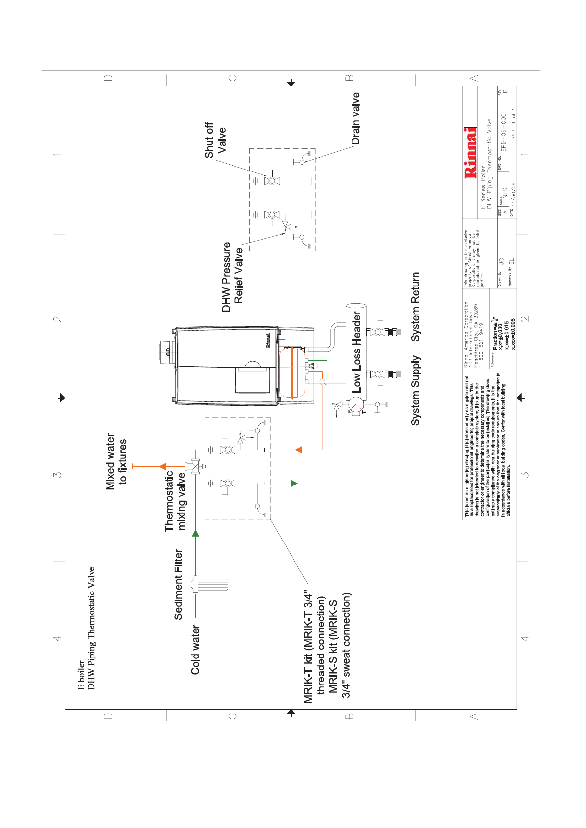
EPD-09-0001 Rev B ............ E Series Boiler .............. DHW Piping Thermostatic Valve ...................... 3
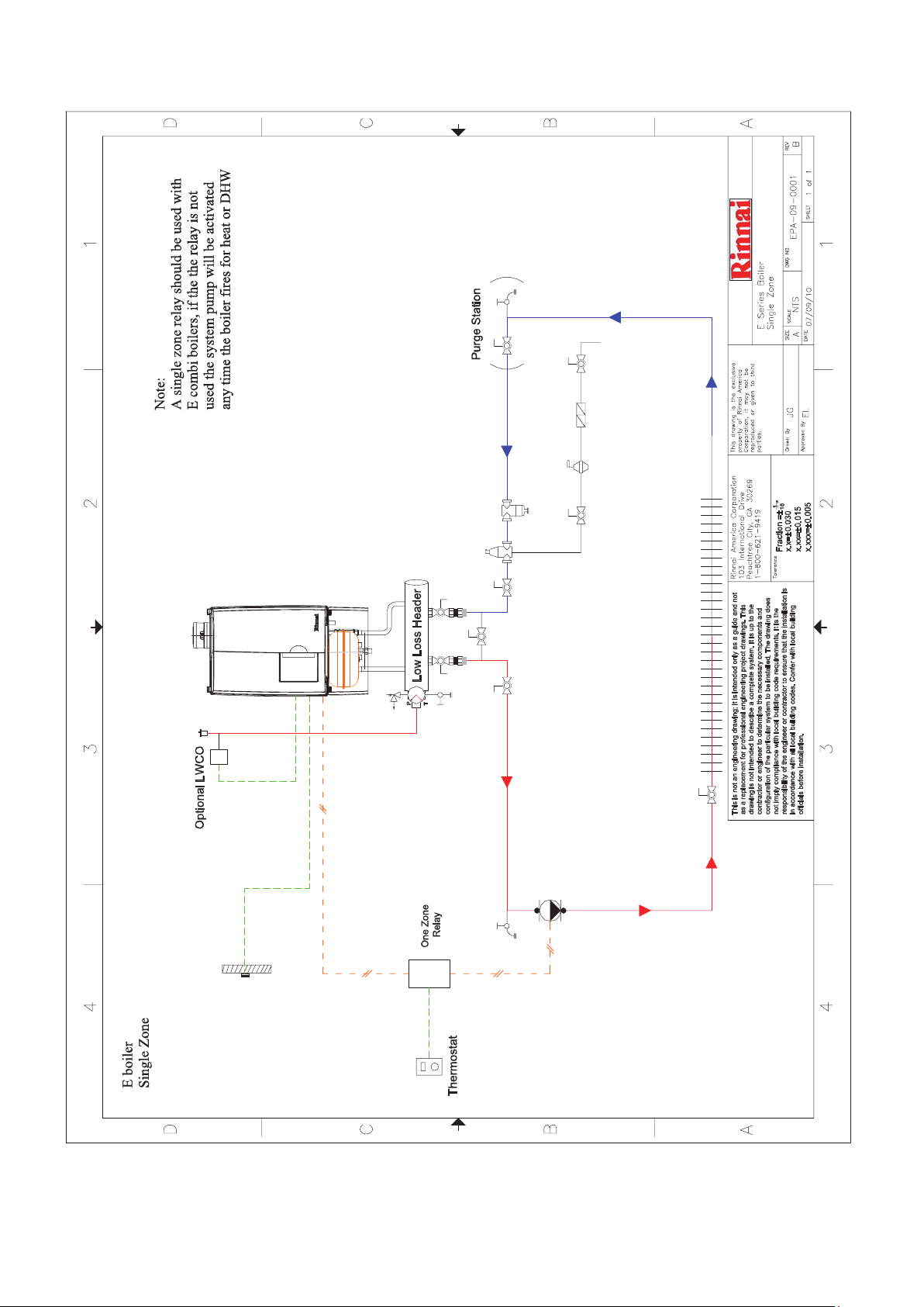
EPA-09-0001 Rev B ............ E Series Boiler ............. Single Zone ....................................................... 4
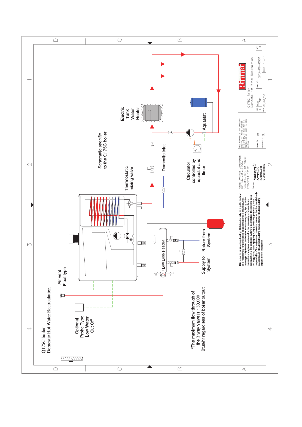
QPD-09-0001 Rev B ........... Q175C Boiler ............... DHW Recirculation ........................................... 5
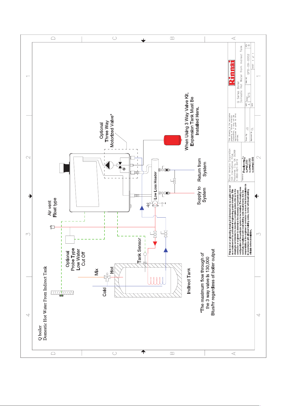
QPD-09-0002 Rev B ........... Q Series Boiler ............. DHW from Indirect Tank ................................... 6
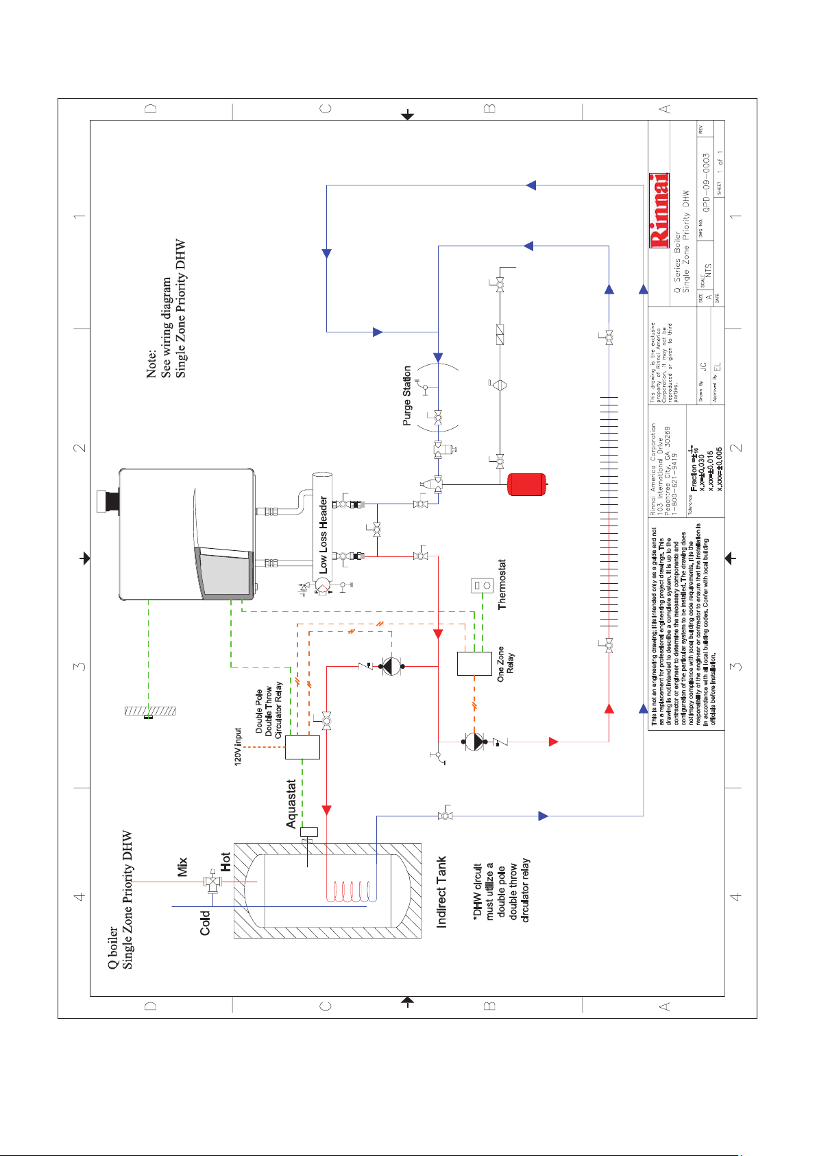
QPD-09-0003 Rev B ........... Q Series Boiler ............. Single Zone Priority DHW ................................. 7
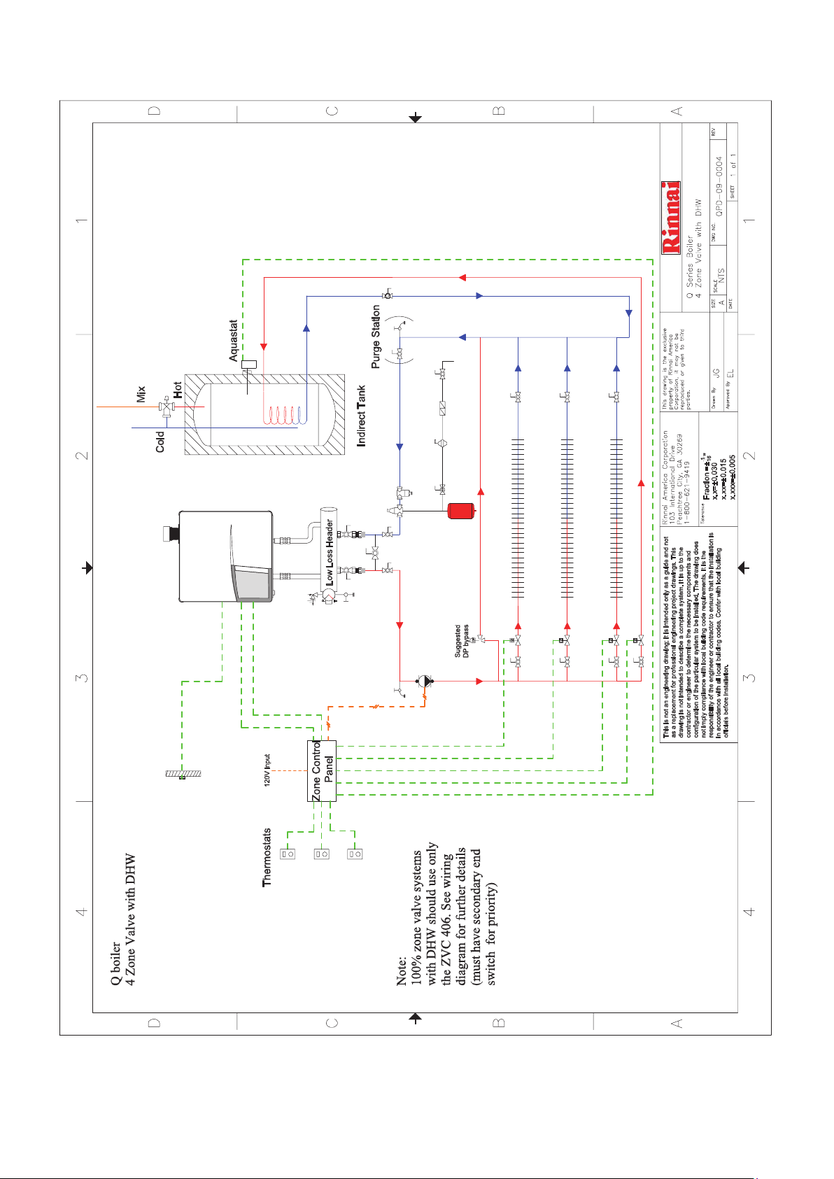
QPD-09-0004 Rev B ........... Q Series Boiler .............. 4 Zone Valve with DHW ................................... 8
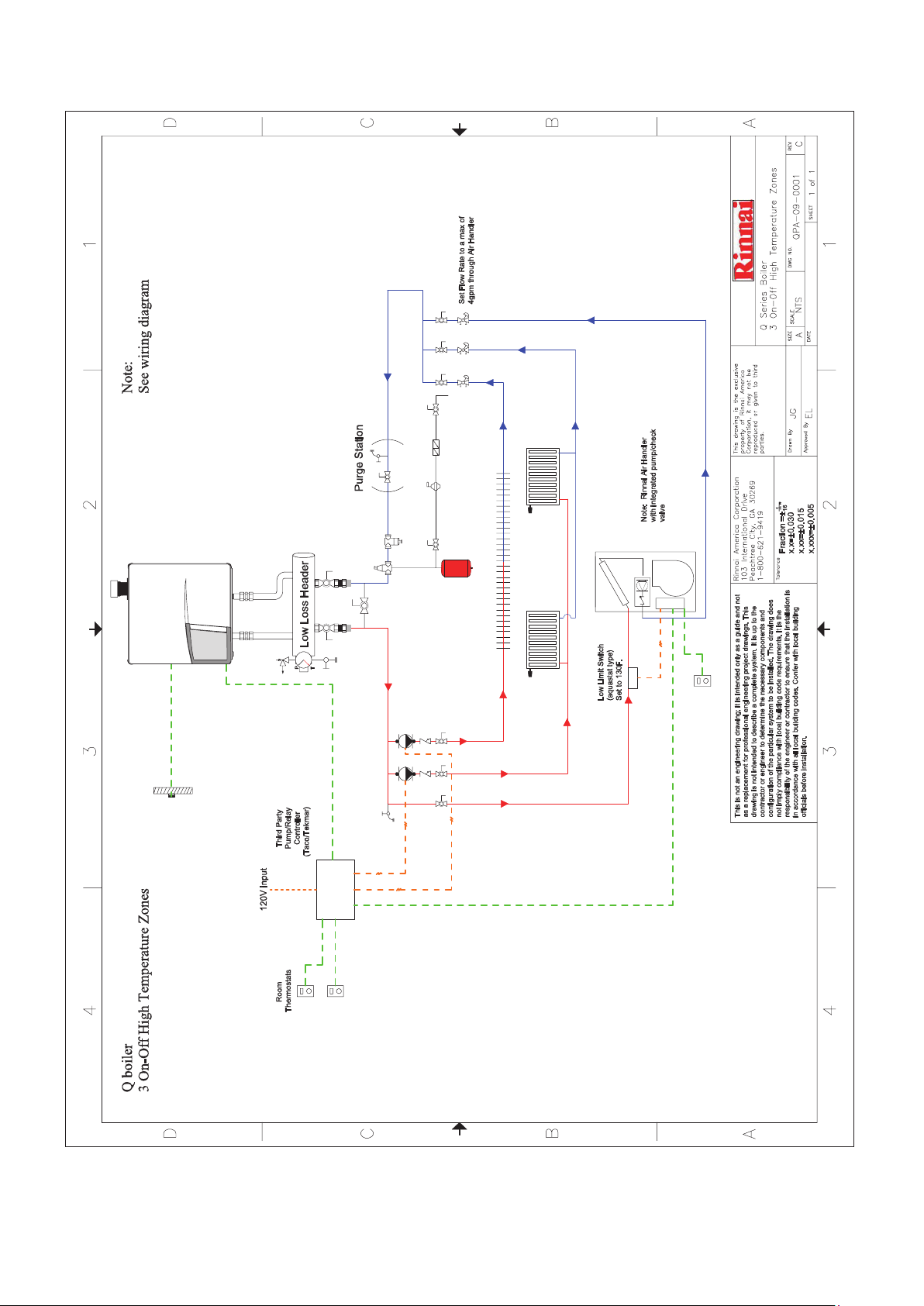
QPA-09-0001 Rev C ........... Q Series Boiler .............. 3 On-Off High Temperature Zones ................... 9
QPA-09-0002 Rev B ............ Q Series Boiler .............. 3 Way Thermostatic Mixing ............................ 10
QPA-09-0003 Rev B ............ Q Series Boiler .............. 3 Way Motorized Mixing ................................. 11
QPA-09-0004 Rev B ............ Q Series Boiler .............. 3 Zone Valve................................................... 12
QPA-09-0005 Rev C ........... Q Series Boiler .............. Direct Coupled Radiant .................................. 13
QPA-09-0006 Rev B ............ Q Series Boiler .............. Single Zone Split Loop ................................... 14
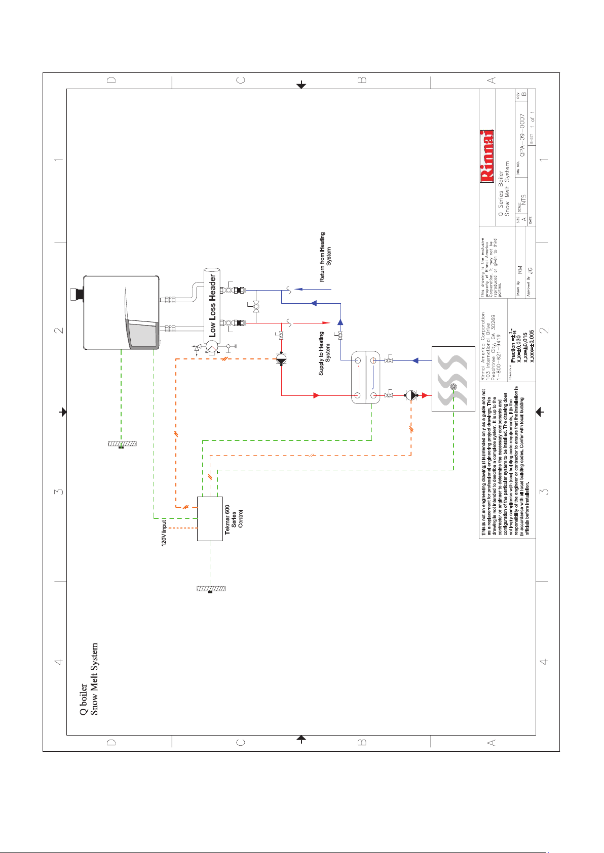
QPA-09-0007 Rev B ............ Q Series Boiler .............. Snow Melt System .......................................... 15
QPA-09-0008 Rev B ............ Q Series Boiler .............. 3 Zone Pumps ................................................ 16
QPA-09-0009 Rev B ............ Q & E Series Boilers ..... Condensate Plumbing with and
without Neutralizer .......................................... 17
QPC-09-0001 Rev B ........... Q Series Boilers ............ 2 Boiler Install ................................................. 18
QPC-09-0002 Rev B ........... Q Series Boilers ............ 3 Boiler Install ................................................. 19
QPC-09-0003 Rev B ........... Q Series Boilers ............ 2 Boilers with DHW ......................................... 20
QEC-09-0001 Rev A ........... Q Series Boilers ............ 2 Boilers with DHW Indirect Tank ................... 21
QED-09-0001 Rev B ........... Q Series Boilers ............ Single Zone Circuit with Priority DHW ............ 22
QED-09-0002 Rev A ........... Q Series Boilers ............ 4 Zone Valves with Priority DHW ................... 23
LEGEND Rev A ................... Q & E Series Boilers ..... Legend ............................................................ 24
Rinnai is continually updating and improving products; therefore, drawings and specifications are
subject to change without prior notice. Local, state, provincial and federal codes must be adhered to
prior to installation.
2 Boiler Applications Manual 800000026 Rev B
Page 3
3 Boiler Applications Manual 800000026 Rev B
Page 4
4 Boiler Applications Manual 800000026 Rev B
Page 5
5 Boiler Applications Manual 800000026 Rev B
Page 6
07/29/2010
6 Boiler Applications Manual 800000026 Rev B
Page 7
B
07/09/10
7 Boiler Applications Manual 800000026 Rev B
Page 8
B
07/09/10
8 Boiler Applications Manual 800000026 Rev B
Page 9
07/09/10
9 Boiler Applications Manual 800000026 Rev B
Page 10

B
07/09/10
10 Boiler Applications Manual 800000026 Rev B
Page 11

07/09/10
11 Boiler Applications Manual 800000026 Rev B
Page 12

07/09/10
12 Boiler Applications Manual 800000026 Rev B
Page 13

C
07/09/10
13 Boiler Applications Manual 800000026 Rev B
Page 14

07/09/10
14 Boiler Applications Manual 800000026 Rev B
Page 15
07/09/10
15 Boiler Applications Manual 800000026 Rev B
Page 16

07/09/10
16 Boiler Applications Manual 800000026 Rev B
Page 17

17 Boiler Applications Manual 800000026 Rev B
Page 18

07/09/10
18 Boiler Applications Manual 800000026 Rev B
Page 19

07/09/10
19 Boiler Applications Manual 800000026 Rev B
Page 20

20 Boiler Applications Manual 800000026 Rev B
Page 21

D
Room
On/Off
Therm.
B
Bus
21 22 23
Controller
Sensor
Outside
Sensor
Outdoor
C
B
A
AA
REV
1 of 1
SHEET
1
QEC-09-0001
DWG NO.
DHW
Boiler 2
sensor
Room
On/Off
N A
14 15 16 17 19 2018
Cylinder connection
W
DH
Three way valve
12 13
CH
Therm.
B
Bus
21 22 23
Controller
Sensor
Outside
Sensor
Outdoor
This drawing is the exclusive
property of Rinnai America
TPST
Corporation, it may not be
NTS
SCALE
Q Series Boiler
reproduced or given to third
parties.
12/09/09
2 boilers with DHW indirect tank
SIZE
DATE
EL
JG
Approved By
Drawn By
120V Relay
DHW
2 1
sensor
Boiler 1
N A
14 15 16 17 19 2018
Cylinder connection
W
DH
Three way valve
12 13
CH
11
10
91
8
6
Rinnai America Corporation
DHW
1/16"
Fraction =±
Tolerance
103 International Drive
Peachtree City, GA 30269
1-800-621-9419
2
x.x=±0. 030
x.xx=±0 .015
x.xxx=±0 .005
Circulator
Sensor
Outdoor
262
20 21 22
19
Com OutBoilDHW
3
Donot apply power
Sw
Com 10K UnO
tN2
tN1/
Supply
Sensor
DHW
Sensor
2
3
3
contractor or engineer to determine the necessary compone nts and
This is not an engineering drawing; it is intended only as a guide and not
as a replacement for professional engineering project draw ings. This
drawing is not intended to describe a complete system. It is up to the
configuration of the particular system to be installed. The drawin gd oes
not imply compliance with local building code requirements. It is the
responsibility of the engineer or contractor to ensure tha tt he installation is
in accordance with all local building codes. Confer w ith local building
L
N
officials before installation.
10A 10A
10A 10A
4
Q Serie s boilers
2 boilers with DHW indirect tank
D
Stage Stage
1 1 2 2
Pmp/Vlv
87
Boil DHW
Power
N L P1
Heating
Circulator
Input
120V
120V
Low voltage
4
Setp
Dem
Dem
DHW
Com
Boiler
Demand Dem
1 2 3 4 5 6 9 10 11 12 13 14 15 16 17 18
L
N
Input
120V
C
Heat Demand From
Thermostat/zone control
Note:
See 2 boiler with DHW indirect
tank drawing
B
A
21 Boiler Applications Manual 800000026 Rev B
Page 22

D
24V~
100mA
Safety
contact
External
C
B
53H
Room
On/Off
Therm.
24
VAC
B
Bus
21 22 23 24 26 2725
Controller
COM
TT
WR
T stat
Sensor
Outside
DHW
sensor
N A
14 15 16 17 19 2018
Cylinder connection
W
DH
Three way valve
2 1
L
120V
Pump
Relay*
Heating
6
N/O
6
N/C
4
N/C
4
N/O
INPUT
N
120 VAC
Zone
Pump
A
BA
REV
1 of 1
SHEET
1
QED-09-0001
DWG NO.
NTS
SCALE
Q Series Boiler
This drawing is the exclusive
property of Rinnai America
Corporation, it may not be
reproduced or given to third
parties.
Rinnai America Corporation
103 International Drive
Peachtree City, GA 30269
1-800-621-9419
12/09/09
Single Zone Circuit with Priority DHW
SIZE
DATE
EL
JG
Approved By
Drawn By
1/16"
Fraction =±
Tolerance
2
x.x=±0.03 0
x.xx=±0 .015
x.xxx=±0 .005
120V
External
controller
120V
External pump
3
N L LN N L N CH
120V
Power supply
1 2 3 4 6 75 8 9 10 12 1 311
For
DHW
Aquastat
24
WR
DHW
VAC
COM
TT
Relay
Pump
53H
6
N/O
6
N/C
4
N/C
4
N/O
INPUT
N
120 VAC
4
DHW
Pump
3
This is not an engineering drawing; it is intended only as a gu ide and not
as a replacement for professional engineering project drawings . This
drawing is not intended to describe a complete system. It is up to the
contractor or engineer to determine the necessary com ponents and
configuration of the particular system to be installed. The dra wing does
not imply compliance with local building code requirements. It is the
responsibility of the engineer or contractor to ensure tha tt he installation is
in accordance with all local building codes. Confer with local building
officials before installation.
120V
Low voltage
4
zone relay
120V
Note: See piping
diagram Single Zone
Q boiler
Single Zone Circuit with Priority DHW
D
C
B
Priority DHW
*May substitute for multi
A
22 Boiler Applications Manual 800000026 Rev B
Page 23

2 1
D
24V~
100mA
Safety
contact
External
Room
On/Off
Therm.
B
Bus
Cylinder connection
120V
21 22 23 24 26 2725
Controller
Sensor
Outside
DHW
sensor
N A
14 15 16 17 19 2018
W
DH
Three way valve
L
For
stat
Aqua
DHW
C
OFF
ON
ZONE 6 PRIORITY
T T
ZONE 6
Sensor
Outdoor
T T
ZONE5
T T
ZONE 4
ZVC 406
T
stat
T T
ZONE 3
ZONE 6
ZONE 5
ZONE4
WITH OPTIONAL PRIORITY
ZONE 3
SIXZONEZONE VALVE CONTROL
B
1 2 3 4
1 2 3 4
1 2 3 4
1 2 3 4
123
123
Note:
4 wire zone valves may also be used
A
AA
REV
1 of 1
SHEET
1
QED-09-0002
DWG NO.
NTS
SCALE
Q Series Boiler
This drawing is the exclusive
property of Rinnai America
Corporation, it may not be
reproduced or given to third
parties.
Rinnai America Corporation
103 International Drive
Peachtree City, GA 30269
1-800-621-9419
12/17/09
4 Zone Valves with Priority DHW
SIZE
DATE
EL
JG
Approved By
Drawn By
1/16"
Fraction =±
Tolerance
2
x.x=±0.03 0
x.xx=±0. 015
x.xxx=±0 .005
120V
120V
External
controller
External pump
T
stat
T
stat
T T
ZONE2
T T
ZONE 1
3
N L LN N L N CH
120V
Power supply
1 2 3 4 6 75 8 9 10 12 1311
RESET
MODE
NORMAL
POWERIN
4
24V
Input
Note: 100% zone valve systems
with DHW should use only the
Q boiler
4 Zone Valves with Priorit y DHW
ZVC 406
Input
120V
D
C
ZONE 2
1 2 3 4
ZONE1
1 2 3 4
123
123
System
Circulator
3
FUSE
(7A MPMAX)
ZONE 6 RELAY
N/O N/CCOM
END
EXTRA
SWITCH
END
MAIN
SWITCH
This is not an engineering drawing; it is intended only as a gui de and not
as a replacement for professional engineering project drawi ngs. This
drawing is not intended to describe a complete system. It is up to the
contractor or engineer to determine the necessary com ponents and
configuration of the particular system to be installed. The drawing does
not imply compliance with local building code requirements. It is the
responsibility of the engineer or contractor to ensure that t he installation is
in accordance with all local building codes. Confer with local b uilding
officials before installation.
120V
Low voltage
4
24V
Input
Note:
Switch positions and jumpers
B
A
23 Boiler Applications Manual 800000026 Rev B
Page 24

24 Boiler Applications Manual 800000026 Rev B
Page 25

Notes
25 Boiler Applications Manual 800000026 Rev B
Page 26

Notes
25 Boiler Applications Manual 800000026 Rev B
Page 27

Notes
25 Boiler Applications Manual 800000026 Rev B
Page 28

Boiler Applications Manual
800000026 Rev B
8/2010
 Loading...