

Page 1
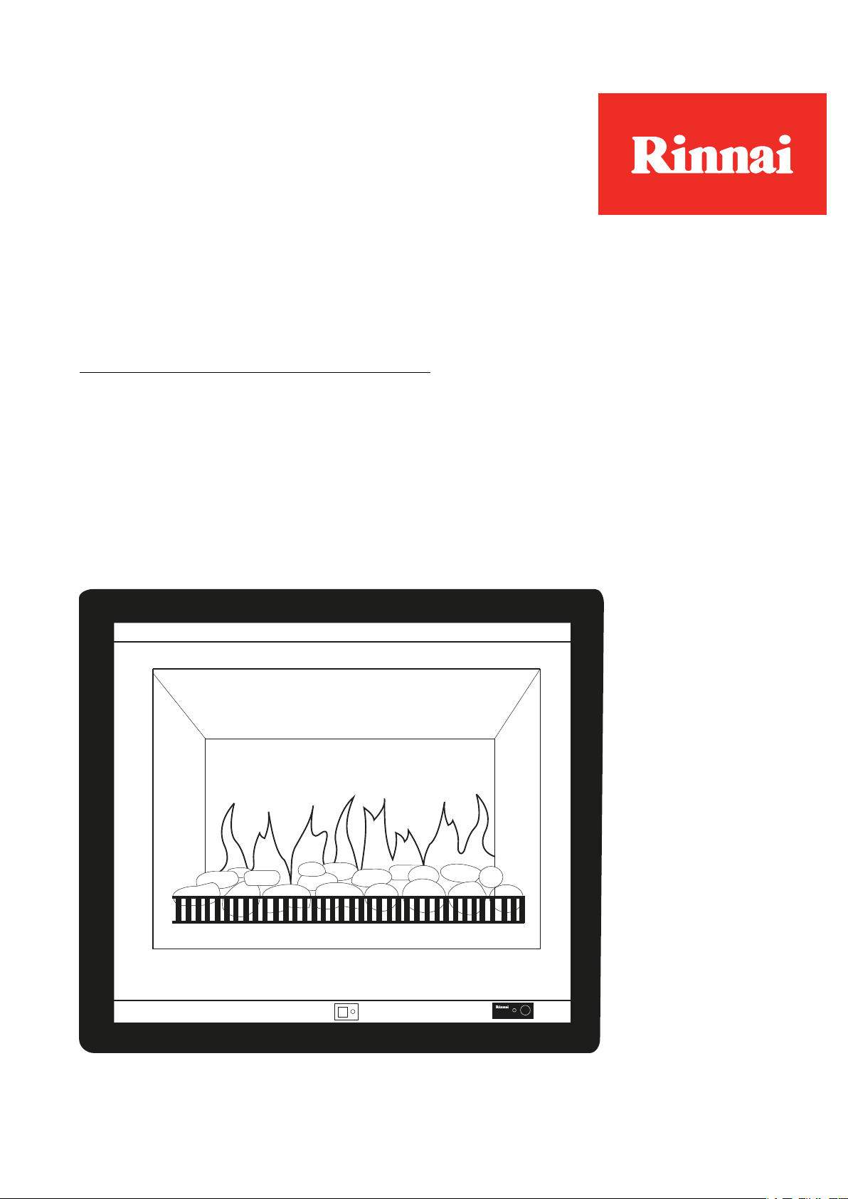
Installation guide
Ember
Models: RDV600N/RDV600L
RDV700N/RDV700L
Page 2

Important:
Appliance must be installed with a Rinnai approved flue
system.
This appliance shall be installed in accordance with:
- Manufacturer’s installation instructions
- AS/NZS 5601 Gas Installations
Installation, servicing and repair shall be carried out only
by authorised personnel.
Warning
Improper installation, adjustment, alteration, service or
maintenance can cause property damage, personal injury
or loss of life.
For more information about buying, using,
and servicing of Rinnai appliances call:
0800 RINNAI (0800 746 624).
Rinnai New Zealand Limited
105 Pavilion Drive, Mangere, Auckland
PO Box 53177, Auckland Airport, Auckland 2150
Phone: (09) 257 3800
Email: [email protected]
Web: www.rinnai.co.nz
www.youtube.com/rinnainz
www.facebook.com/rinnainz
cnt:
Before you start .......................................................... 4
Ember specification ...................................................5
Dimensions .................................................................6
Gas and electrical supply ............................................ 8
Enclosure dimensions ................................................9
Clearances from combustibles ................................... 10
TV installation .............................................................12
Ember masonry installation overview ........................14
Ember mock chimney installation overview .............. 16
Installing the zero clearance frame ............................18
Attaching the flexi flues to the spigot plate ...............19
Burn media installation ............................................... 20
Adding the glass and vermiculite ...............................21
Log set installation .....................................................22
Stone set installation ..................................................24
Commissioning ..........................................................26
Installing the frame.....................................................27
Test operation and lighting sequence ........................28
Installation checklist and customer handover ...........28
Wiring diagram ........................................................... 29
Ember flueing ............................................................. 30
Flueing options ...........................................................32
Horizontal terminations (mock chimney) .................. 33
Vertical terminations (mock chimney).......................34
Vertical termination (masonry chimney) ...................35
Horizontal termination (masonry chimney) ..............36
Flue kits and components ..........................................37
Page 3
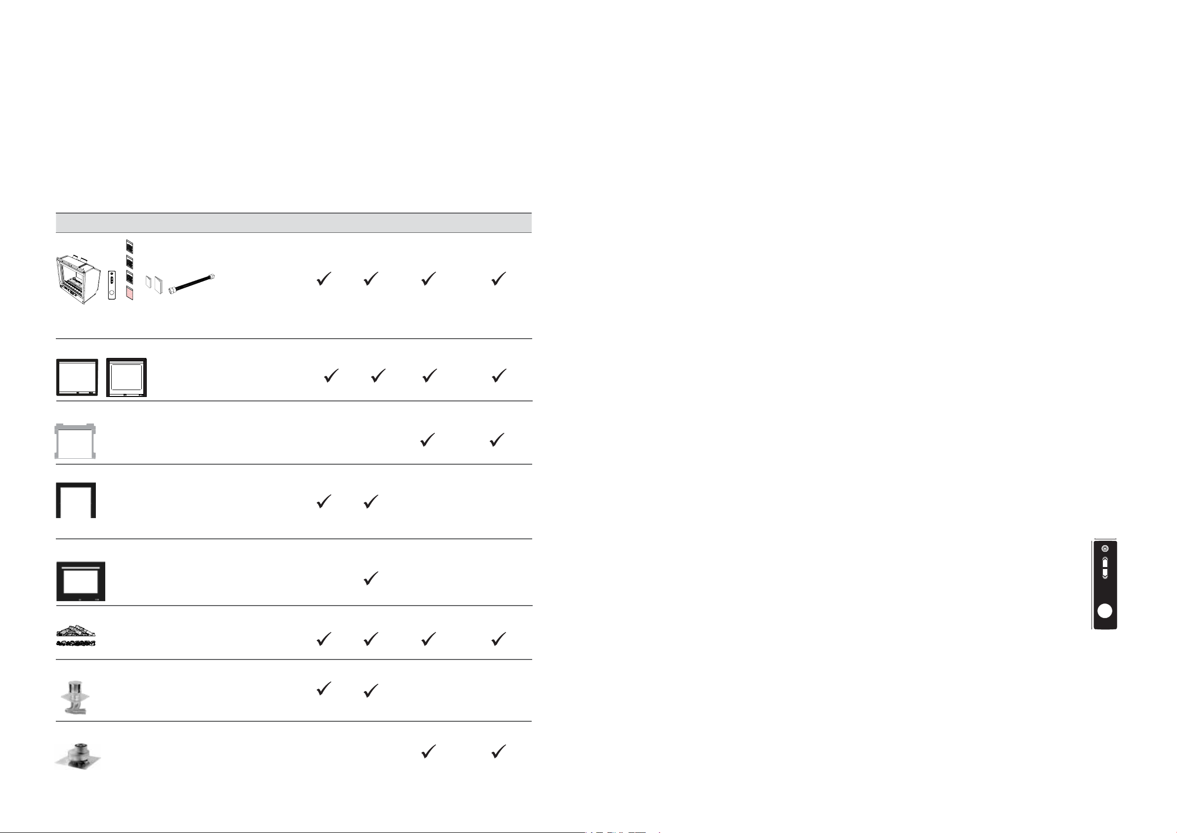
Ember specicationBefore you start
Unpack the appliance and components and check for damage. DO NOT install any damaged items.
Check all components have been supplied and that you have the correct gas type.
Read these instructions to get an overview of the steps required before starting the installation. Failure
to follow these instructions could cause a malfunction of the appliance. This could result in serious injury
and/or property damage.
Ensure the flue termination will meet the required flue clearances as shown in AS/NZS 5601.1 before
installation.
Item Masonry installation Mock chimney installation
Ember 600 Ember 700 Ember 600 Ember 700
Engine
The Ember engine comes with; remote control (batteries inserted), operation and installation guides, granule packs, rockwool,
crushed glass, vermiculite, and flexible gas connection.
4-sided or 3-sided frame
Zero clearance frame
A must-have for mock chimney installations as it
gives automatic clearances to combustibles and
is critical for keeping the installation square.
Infill panel (if needed)
Infill panel only needed if the cavity is slightly larger than the framepanel will cover the gap behind the fire and 3-sided frame.
700 Masonry frame
Wider masonry frame for the Ember 700,
designed to cover a larger cavity opening.
Burn media
Masonry flue components
Mock chimney flue components
Option of a log or stone setensure you
have the correct set before starting, they are
different for each model.
Flexi flue components for a vertical or
horizontal chimney termination
Flue components for a vertical or horizontal
termination.
Ember 600 specification summary
Input = 12-23 MJ/h
Output = 2.5-5.0* kW
Efficiency = 77% (on high)
Heating area = up to 85 m
2
**
Gas type = NG or ULPG
Ember 700 specification summary
Input = 14-27 MJ/h
Output = 3-6.0* kW
Efficiency = 77% (on high)
Heating area = up to 99 m
2
**
Gas type = NG or ULPG
A direct vent inbuilt gas fireplace with a glass front
and convection fan, pushing warm air from the
top of the appliance. Operated with an infra-red
remote control.
Different burn media and frame options available.
* Will vary according to gas type and flue configuration.
** Will vary depending on geographical location in NZ.
Suitability
Suitable for masonry installations and installations
into a mock chimney, in open plan areas and living
rooms.
Data plate
Located on the lower RHS of the base panel in
front of the gas control.
Convection fan
120 V AC 50 Hz 2-speed centrifugal blower.
Lighting
Halogen lamps 240 V 25 W x 2.
Gas connection
Brass ½ “ BSPT male fitting, the gas supply
terminates inside the heaterlower right hand
side of the appliance.
Ignition
230-240 V AC 50 Hz high voltage electronic spark
generation unit.
Installation considerations
Room sizesmaller rooms will heat up quickly,
and due to the efficiency of the appliance, the
Ember will turn to a low flame setting once the set
temperature has been reached.
For efficient performance Rinnai recommends
installing the fire as close to the floor as possible.
If the unit is installed higher up the wall the
movement of air from the convection fan,
depending on the room configuration, could
create draughts.
Noise level: 37-45 dB(A)
Flueing: Masonry
Colinear flexi flue, air intake Ø 75 mm, exhaust
Ø 100 mm. Appliance must be installed with a
Rinnai Ember flue system.
Flueing: Mock chimney
Colinear (air intake Ø 75 mm, exhaust Ø 100 mm)
to coaxial direct vent flueing (inner Ø 100 mm,
outer Ø 170 mm). Appliance must be installed with
a Rinnai Ember flue system.
Electrical
This heater has a 1.5 m power cord with a three pin
plug supplied. The power cord passes through a
slot in the back left hand corner of the appliance.
• High = 110 W
• Standby = <1W
Safety devices
Flame failure sensing system, pressure relief,
overheat safety switch, air temperature sensor,
thermal fuse, overcurrent fuse, and spark
detector.
Temperature control
34 mm
Once the unit is turned on the infra-red
remote* is used to control the flame
height and heat output.
136 mm
If the remote is not used the Ember will
automatically modulate between the
23
burner settings to maintain the default
set temperature of 22 °C.
* Temperature sensor is located in the bottom of the remote
depth - 11 mm
Weights
• Ember 600 = 51 kg
• Ember 700 = 55 kg
4 | Ember Installation Guide: 12890-B 02-18
Ember Installation Guide: 12890-B 02-18 | 5
Page 4
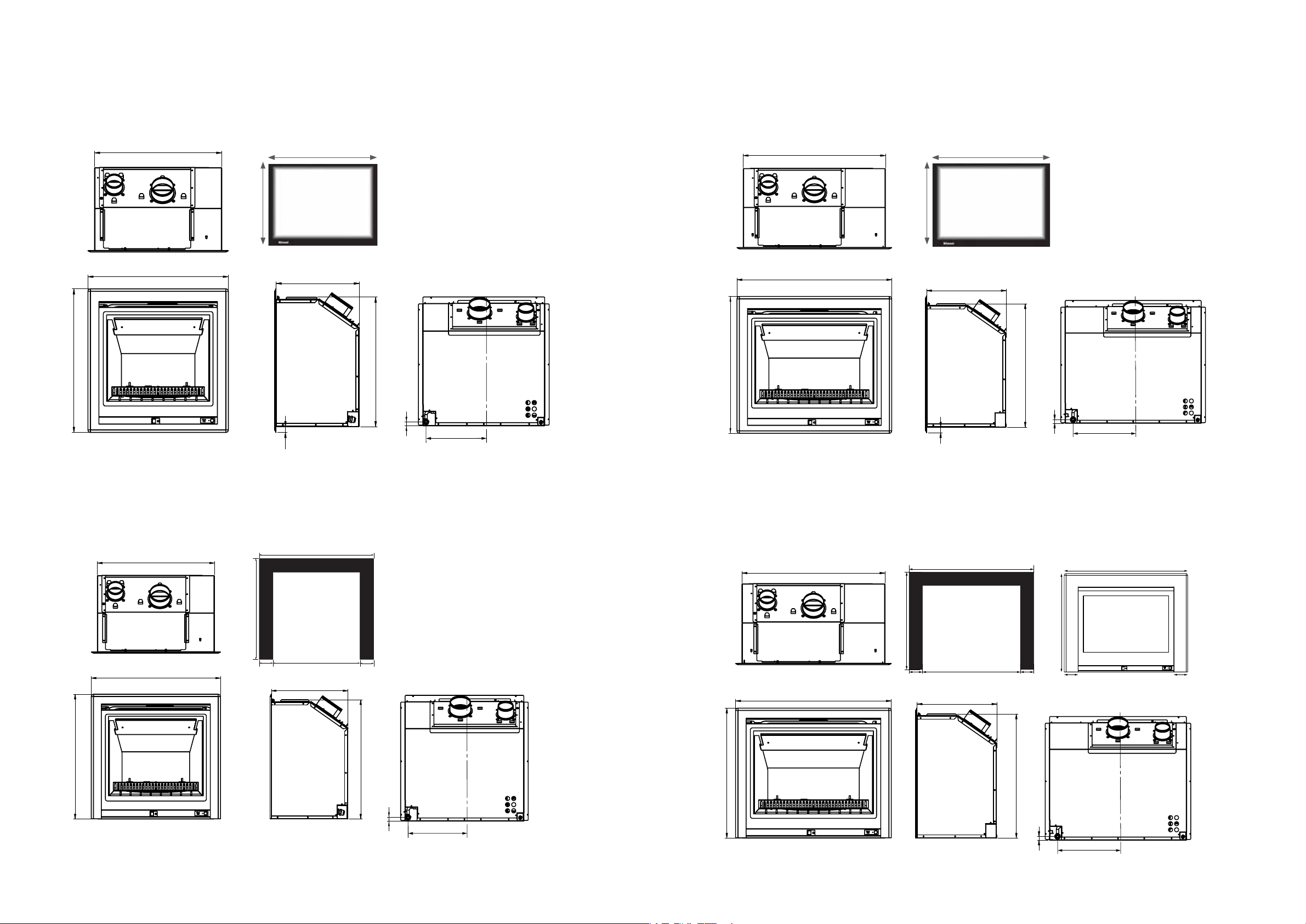
Dimensions (mm)
26
Ember 600 with 4-sided frame (mock chimney installations) Ember 700 with 4-sided frame (mock chimney installations)
644
580
640
540 mm
Viewable glass
dimensions, same
for both 600
500 mm
models
26
380
590
18
287
644
680
740
640 mm
Viewable glass
dimensions, same
for both 700
500 mm
models
380
590
18
312
Ember 600 with 3-sided frame (masonry installations or mock
chimney installations with a hearth)
790
infill panel
380
590
18
287
618
580
640
695
95 95600
Ember 700 with 3-sided frame (masonry installations or mock
chimney installations with a hearth)
618
680
740
890
infill panel
695
95 95
700
380
590
658
92.5 92.5
18
312
825
masonry
frame
6 | Ember Installation Guide: 12890-B 02-18
Ember Installation Guide: 12890-B 02-18 | 7
Page 5
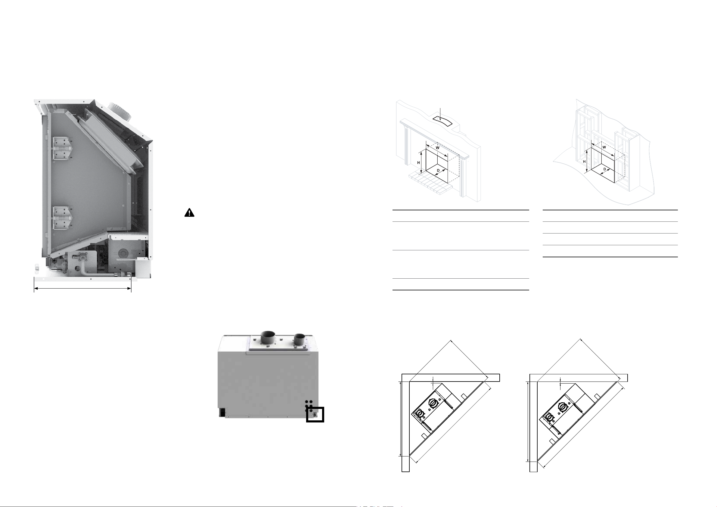
Gas supply
993
Enclosure dimensions
Gas pipe sizing must consider the gas input to this appliance, as well as other gas
appliances in the premises. The gas supply termination is inside the heater, and
enters from the lower right hand side of the appliance.
Purging the gas supply
Foreign materials and debris such as swarf,
filings etc. must be purged from the gas
supply. Failure to do so may cause damage to
the control valve causing it to malfunction.
Gas connection
A small spanner has been provided, located
in the commissioning pouch on top of the
PCB cover, to help with the gas connection as
space is quite tight. Please return the spanner
to the pouch when finished.
The use of a rubber hose for any gas
connection to a fixed appliance is not
authorised by the manufacturer.
The Ember must be positioned within the enclosure on a flat level surface that
allows free movement of the appliance. The enclosure must be capable of
supporting 1.5 times the weight of the Ember.
Masonry
Actual chimney size needs to be at least 200 x 200 mm
for the two flexi flues to fit down the chimney.
600 700
W-width
Infill panel*
Masonry frame*
H-height
Infill panel*
Masonry frame*
600 mm
600-750 mm
N/A
600 mm
600-675 mm
N/A
700 mm
700-850 mm
700-785 mm
600 mm
600-675 mm
600-638 mm
Mock chimney
600 700
W-width 700 mm 800 mm
H-height 700 mm 700 mm
D-depth 400 mm min. 400 mm min.
Framing dimensions above are before the zero clearance
frame is fitted.
approx. 320 mm
Electrical supply
The Ember is fitted with a 1.5 m power cord and 3-pin plug.
The power cord passes through a slot in the back left hand
corner of the appliance.
The connection is either direct wired* or connected to a
power point within the cavity. This must be connected to
a dedicated earthed power point. The electric isolation
switch must be accessible after the appliance has been
installed.
The fire must not be located immediately below a socket
outlet (potential fire hazard).
If the supply cord is damaged, it must be replaced by a licensed tradesperson. This must be a
genuine replacement part available from Rinnai.
* Consult a qualified electrician if direct wiring is required as it must comply with AS/NZS 5601 and AS/NZS 3000 and other
relevant local regulations
D-depth 400 mm min. 400 mm min.
* Enclosure dimensions can be larger if using an infill
panel or a masonry frame.
Corner installations
702 min.
Ember 600
25
1404
For mock chimney installations the Ember MUST BE
installed with the Ember Zero Clearance frame, which
gives the required clearances to combustibles.
752 min.
Ember 700
25
1063
1504
8 | Ember Installation Guide: 12890-B 02-18
Ember Installation Guide: 12890-B 02-18 | 9
Page 6
Clearances from combustibles
Glass width
Clearance Clearance
A
c
B-
mantel depth
400 mm
400 mm 400 mm
1000 mm
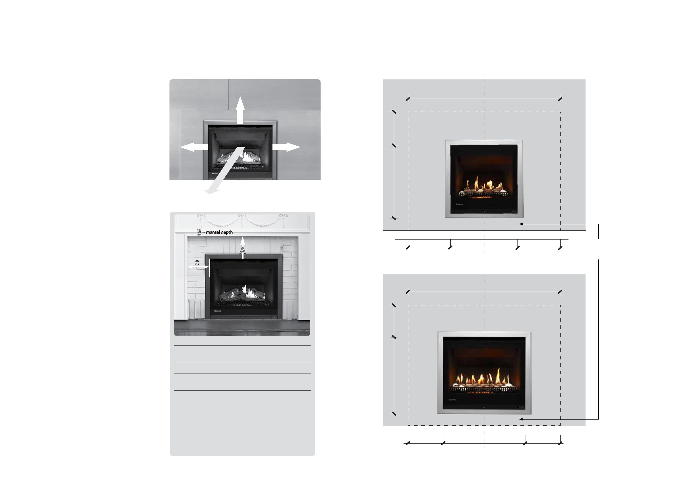
The clearances listed below, measured from the edge of the glass, are
minimum clearances unless otherwise stated.
The below diagrams are to assist people in determining the clearance area around the Ember
without having the unit on site. The 4-sided frame is shown as this is the frame used in mock
chimney installations, which typically have mantels and surrounds made of combustible material.
The 4-sided frame sits approximately 26 mm below the engine, refer dimension diagrams.
While the heater is operating
The appliance must not be installed where
curtains or other combustible materials
could come into contact with the heater.
The 400 mm side clearance includes side
walls. The 1000 mm clearance is in front of
the fire.
Floor protection
Heat from this fire may over time affect
the appearance of some materials used
for flooring, such as, carpet, vinyl, cork
or timber. This may be amplified if the air
contains cooking vapours or cigarette
smoke. To avoid this occurring, it is
recommended that a mat be placed in
front of the appliance.
Mantels and surrounds
Combustible mantels and surrounds
require clearance from the unit to
minimise the risk of fire. Mantels and
surrounds, made of combustible materials
such as wood, are allowed providing they
are outside the minimum clearances
shown.
Ember 600 4-sided frame
1340
Minimum above fire
570 400
Clearance Clearance
Glass width
Ember 700 4-sided frame
1440
Minimum above fire
540400 400
Distance off the floor
could be 0-400 mm.
Hearths
A hearth is not necessary but can be used
for decorative purposes or protection
of sensitive flooring if required. A hearth
must not obscure the front of the fire or
obstruct the fire in any way (including the
frame around the fire).
Wall surface above the fire
The temperature of the wall surface
directly above the fire may get warm
and distort paint finishes, or distort vinyl
wall coverings. For durability of surfaces,
please contact the manufacturer for their
specification.
10 | Ember Installation Guide: 12890-B 02-18
A Mantel needs to be a min. of 400 mm away from the
edge of the glass.
B Max. mantel depth at 400 mm (A) is 250 mm max.
C Surround needs to be a minimum of 400 mm away
from the edge of the glass.
For every 50 mm of added mantel depth there must be
an additional 100 mm of clearance from the edge of the
glass. For example:
Mantel depth A: clearance required
300 mm 500 mm
350 mm 600 mm
400 mm 700 mm
570 400
640400 400
Ember Installation Guide: 12890-B 02-18 | 11
Page 7
TV installation
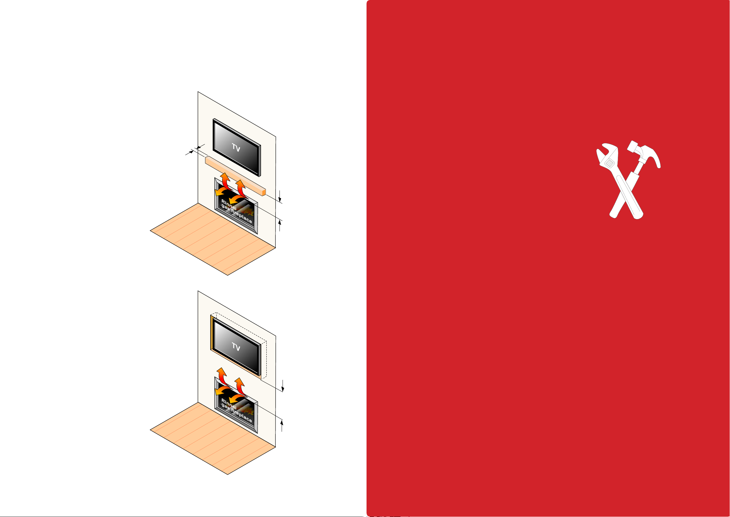
The Ember has a fan that distributes warm air from the top of the appliance
out into the room. As warm air is dispersed outwards, as opposed to directly
upwards, installation of a TV may be an option.
The diagram shows
recommended clearances
when installing a TV directly
above the Ember, or into a
recess. All dimensions are in
millimetres.
400 mm dimension
The 400 mm dimension
is the minimum clearance
required to a mantel. The
image adjacent shows the
dimension from the edge
of the frame, in the case
of the Ember the 400 mm
dimension is to be taken from
the edge of the glass.
At least the
depth of the TV
400 mm
minimum
Installation
Installation, servicing and repair
shall be carried out only by
authorised personnel.
Always check with the TV
manufacturer
It is up to the owner to check
the TV installation with the TV
manufacturersome have
warranty conditions that state
a TV is not to be installed
above a fireplace.
Rinnai does not accept any
responsibility for damage to
a TV resulting from the use of
this information.
400 mm
minimum
12 | Ember Installation Guide: 12890-B 02-18
Ember Installation Guide: 12890-B 02-18 | 13
Page 8
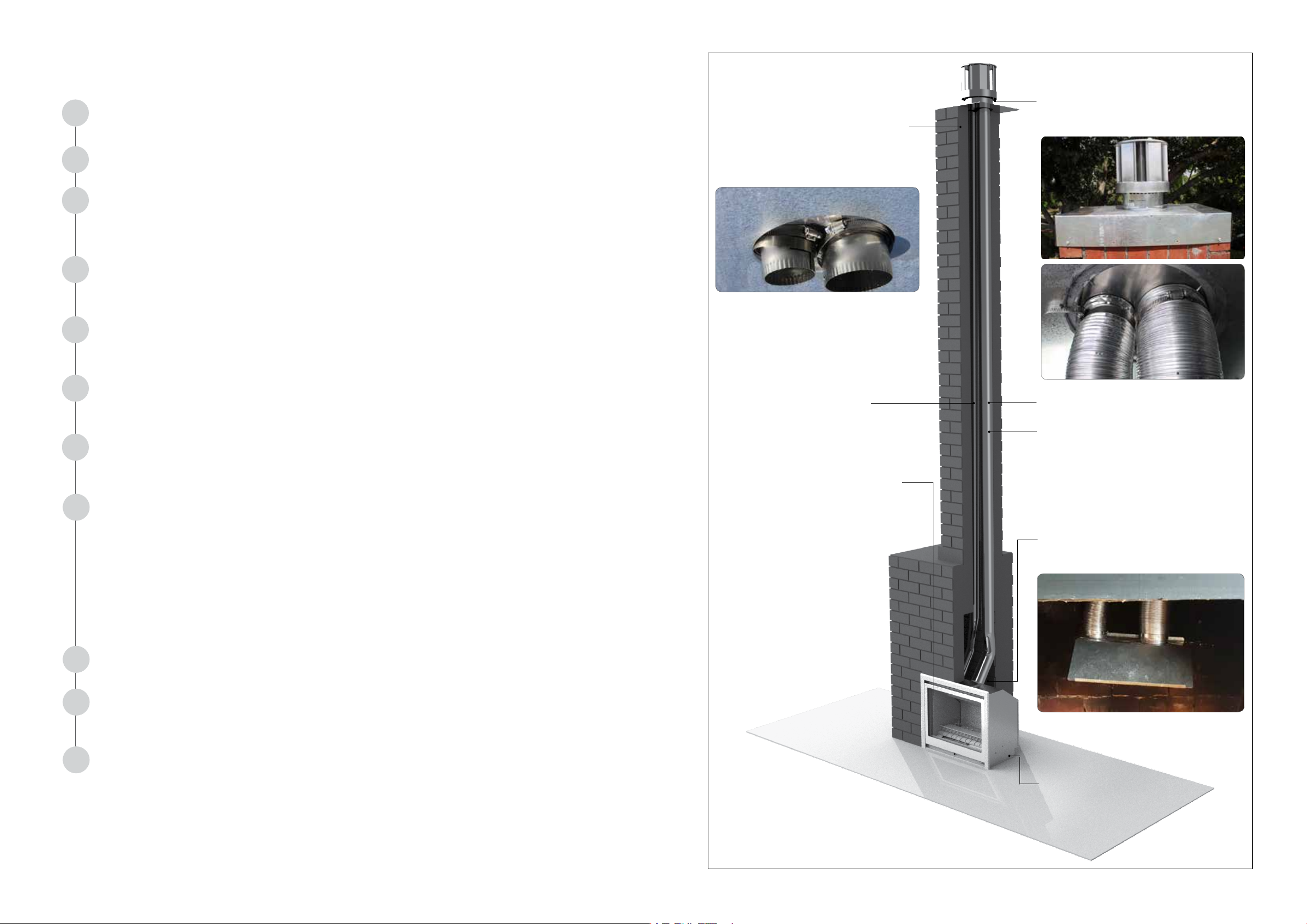
Ember masonry installation overview
Modify the enclosure
1
Ensure the enclosure meets the requirements set out on p. 9.
Gas and electrical connections
2
Prepare gas and electrical connections, refer p. 8.
Connect flexi to flue terminal
3
Stretch out the flexi to the required length and attach to the flue terminal using the
clamps provided. Seal the terminal to the chimney plate and weatherproof any openings
using appropriate silicone sealant.
Drop flexi down chimney
4
Drop the flexi flue down the chimney, making sure you have the intake and exhaust flues
in the correct position, and seal the chimney plate to the chimney.
Attach flexi flues to the flue spigot plate
5
Undo the two front screws holding the flue spigot in place and attach the flexi to the
spigot using the clamps provided. Screw/rivet in place to stop any movement, refer p. 19.
Check the size of the chimney before
doing anything. It needs to be at least
200 x 200 mm for the colinear flexi flue
to fit down.
When dropping the flexi flue down the
chimney make sure you have the intake
and exhaust flues in the correct position.
The intake is on the left.
Make sure the chimney cap is
weathertight. Flexi flue also needs to be
secured to the flue cowl using the clamps
provided—these need to be riveted/
screwed in place to reduce the risk of
movement.
If using the infill panel or masonry frame attach the side brackets
6
Attach the side brackets provided with the infill panel or masonry frame, using the screws
provided, to the Ember engine using the top and bottom fixings.
Attach flue to the fire
7
Line up the spigot plate with the flue guide rails on top of the unit, slide the unit in place,
and secure spigot—two front screws.
Secure Ember to the enclosure
8
This can be done two ways depending on the installation:
1. Secure to the enclosure via the existing flanges on the engine, or
2. If using the infill panel or masonry frame, attach the side brackets* to the Ember
engine with screws*, using the top and bottom fixings. Slide the Ember in place, and
secure the side brackets to the enclosure, using the three outer screw positions on
each bracket, to the brickwork using suitable fixings (not provided).
* Provided with the infill panel or masonry frame
Complete the gas connection
9
Make the gas connection.
Install the burn media and commission
10
Install the glass, granules, rockwool, logs or stones. Refit the combustion chamber glass
and commission, refer p. 20-26.
Intake Ø 75 mm left hand side.
The Ember engine must be secured
to the enclosure via the top and side
flanges. This can be done directly into
the enclosure, into the infill panel or
masonry frame using the side brackets
provided.
Exhaust Ø 100 mm right hand side.
Maximum flue length is 8 m.
Flexi flues clamped and riveted/screwed
in place to the engine spigot plate. Due
to the weight it’s best to support the
underside of the plate to stop the flexi
flues from extending too much.
Install the frame and infill panel (if using)
11
Install the masonry or the 3-sided frame and infill panel* (if using), refer p. 27.
* Separate installation instructions are provided with the infill panel.
14 | Ember Installation Guide: 12890-B 02-18
Base of masonry enclosure MUST
BE level and allow free movement of
the appliance for maintenance and
servicing.
Ember Installation Guide: 12890-B 02-18 | 15
Page 9
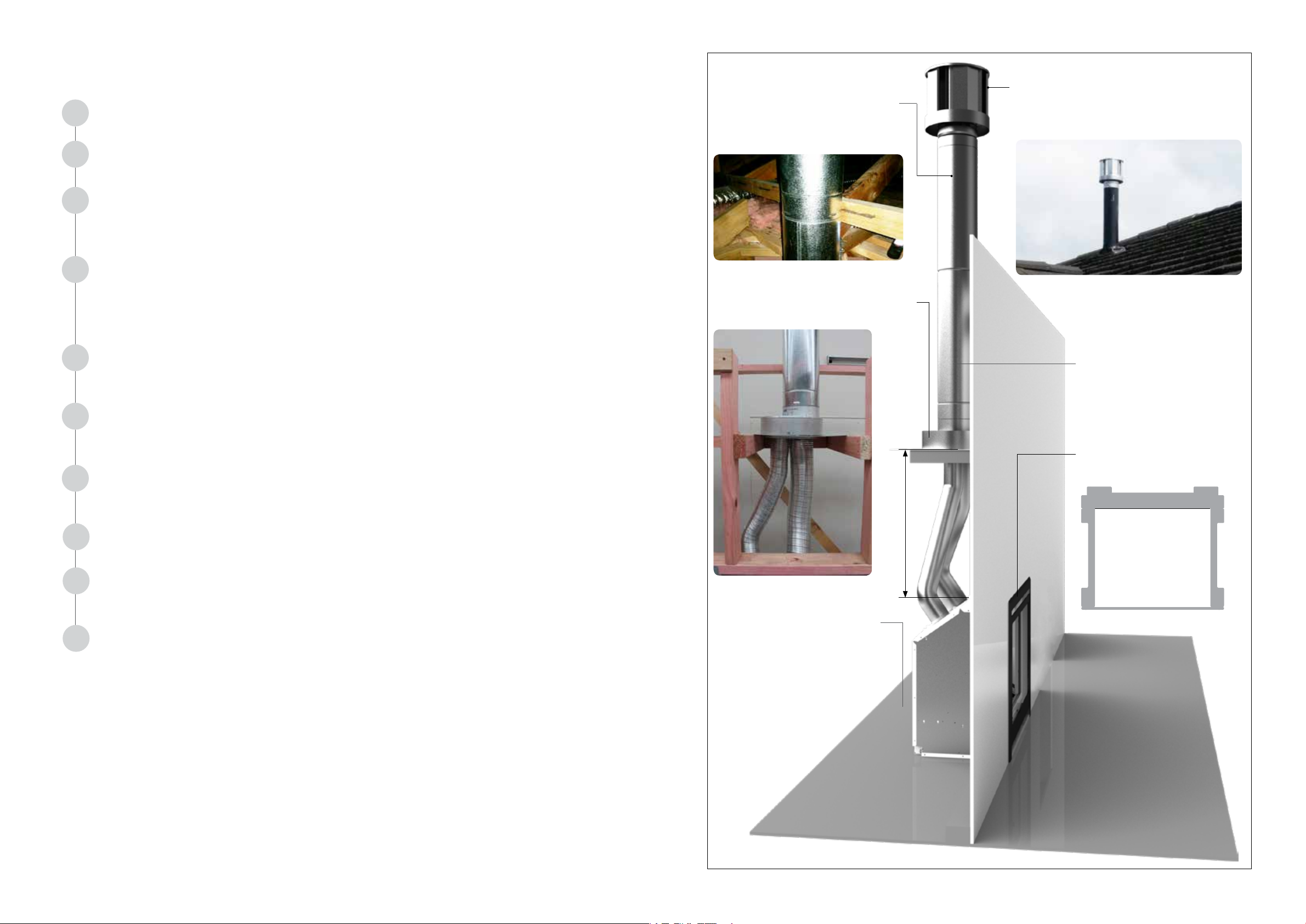
Ember mock chimney installation overview
Modify the enclosure
1
Ensure the enclosure meets the requirements set out on p. 9.
Gas and electrical connections
2
Prepare gas and electrical connections, refer p. 8.
Install the zero clearance frame
3
Install the zero clearance frame into the enclosure and fix in place with the screws
provided. This frame is critical and must be installed as it automatically gives the required
clearances to combustibles. Refer p. 18 for installation details.
Flue system installed
4
Install the coaxial* to colinear adaptor. Ensure it is self supported with the frame and
screwed in place. Attach the intake and exhaust flexi flues to the adaptor, clamp and screw
into placecheck clearances are maintained. Add colinear sections as required, these
twist and lock into place.
Attach flexi flues to the flue spigot plate
5
Undo the two front screws holding the flue spigot in place and attach the flexi to the
spigot using the clamps provided and screw into place, refer p. 19.
Self-supporting coaxial flue; inner
Ø 100 mm, outer Ø 170 mm. Requires
10 mm clearance to a combustible
surface. Flue pipes twist and lock into
place.
Colinear to coaxial adaptor supported
and secured in place. Flexi flues clamped
and screwed to the connections.
Flue cowl needs to a 500 mm clearance from
the nearest ridge line of the roof. In this instance
the flue pipe has been painted to match the
roof.
Maximum vertical flue length
is 10 m. If adding 2 x 45 ° bends
(maximum number of bends),
then the flue length reduces by
2 m, refer p. 33.
Attach the flue spigot back onto the engine
6
Line up the spigot plate with the flue guide rails on top of the unit, slide the unit into place,
and secure the spigottwo front screws.
Secure Ember to the zero clearance frame
7
Secure engine to the zero clearance framenine screw positions (three LHS, three top,
and three RHS).
Complete the gas connection
8
Make the gas connection.
Install the burn media and commission
9
Install the glass, granules, rockwool, logs or stones. Refit the combustion chamber glass
and commission, refer p. 20-26.
Install the frame
10
Install the frame, refer p. 27.
Zero clearance frame fitted
prior to final cladding, refer
next page.
600 mm maximum
Base of enclosure MUST BE level
and allow free movement of the
appliance for maintenance and
servicing.
* Can’t be more than 600 mm maximum due to the heat from the colinear flexi flues.
16 | Ember Installation Guide: 12890-B 02-18
Ember Installation Guide: 12890-B 02-18 | 17
Page 10
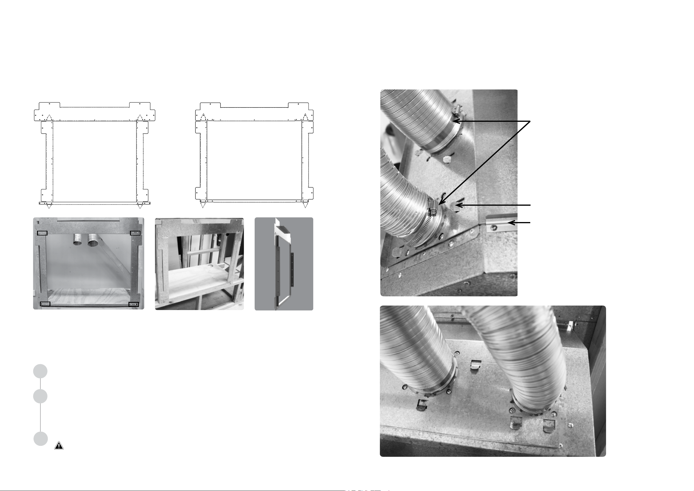
Installing the zero clearance frame
Attaching the exi ues to the spigot plate
For mock chimney installations the zero clearance frame is a mandatory
requirement to ensure a safe installation for the homeowner. It is a universal
frame for both models, that allows for different opening sizes. Refer to the
line drawings below to see how each frame is put together. N.B: The zero
clearance frame is fitted prior to final cladding.
Ember 600 setup
600
To assemble the Ember 600
frame use the inner fixing holes.
Please note the position of the
side and lower brackets.
600
1 1
600
600
700 700
To assemble the Ember 700
frame use the outer fixing holes.
Please note the position of the
side and lower brackets.
700 700
1
Ember 700 setup
2
The flexi flues need to be securely fixed to the engine spigot plate using the
clamps provided. To do this the spigot plate needs to be temporarily removed
from the engine—undo the two front screws holding it in place.
Flue clamp holding the flue onto the
spigot plate. Important: This also needs
to be screwed/riveted in place to stop any
movement of the flue.
Helpful tip
Once the flue is connected to the spigot
plate it will be free-hanging. To avoid
damage to the flue it’s best to support this
within the cavity while waiting to install the
engine.
Tabs to hold the plate in place
Flue guide rail on either side of the engine.
The spigot plate slides in and out of this.
2 2
1 1
3
The frame serves three purposes:
1. Maintains the required clearances to combustibles around the fire
2. Keeps the enclosure square and provides rigidity above the fireplace
3. Allows for a thin profile frame and for the engine to slip easily in and out of the enclosure
Assemble the frame
1
Screw all four sides of the zero clearance frame together.
Fix the frame to the enclosure
2
Fix the assembled frame to the enclosure by screwing through the folded edges of the
side and top sections. Please note that the bottom strip of the zero clearance frame sits
level with the bottom of the cavity.
Remove bottom strip
3
Once the zero clearance frame is securely fixed, the bottom strip needs to be
IMPORTANT
removed. This must be done otherwise the Ember frame will not fit properly.
Top view showing flues clamped and the spigot plate in place on top of the engine
18 | Ember Installation Guide: 12890-B 02-18
Ember Installation Guide: 12890-B 02-18 | 19
Page 11
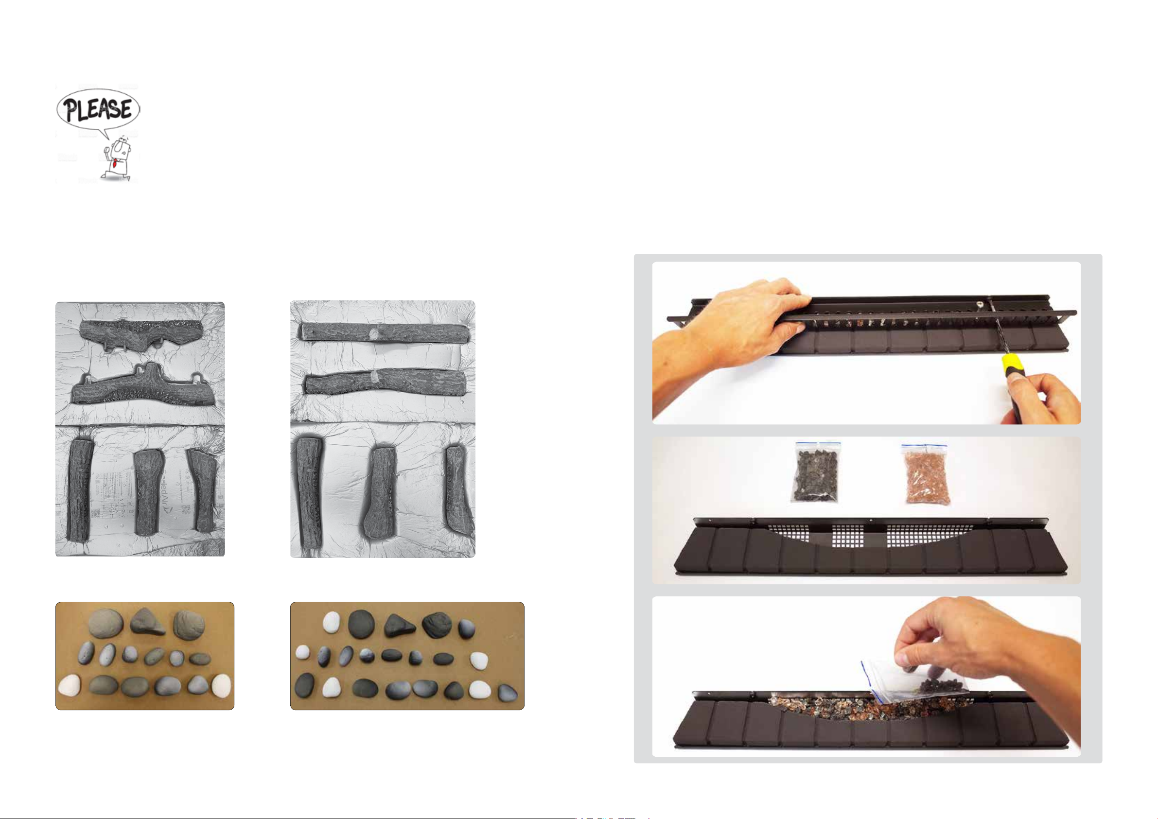
Burn media installation
Adding the glass and vermiculite
Experience has shown that the majority of performance problems
are caused by burn media being installed incorrectly. Please take
the time to read and follow these instructions as malfunctioning
due to incorrect burn media placement is not covered by
warranty.
The Ember MUST NEVER be used with other burn media or burn
media that is damaged.
Ember 600/700 burn media sets - they are different and can’t be interchanged
The Ember 600 and 700 burn media sets are different. The Ember 600 stone set has six less
stones and the log set is narrower and shorter—ensure you have the correct kit before starting.
Ember 600 log set Ember 700 log set
Back log
Front log
This step is common to both models and both types of burn media. It requires
removing the upper burn media tray to access the mesh holding tray.
1. Unscrew the left and right tray screws to lift off the upper mesh holding tray.
2. Carefully empty the bags of vermiculite and glass into the mesh tray, blend
and level out.
3. Put the upper tray back in place and re-tighten the screws.
together
1
Front log
Left log
Ember 600 stone set - laid out in
the correct order
Right log
Middle log
Back log
Left log
Ember 700 stone set - laid out in the correct
order
Right log
Middle log
2
2
Positioning guide picture fixed to the unit will help
There should be a wonderful closeup picture secured to the fire to help you decipher what goes
where. Use this in conjunction with these instructions to help with the installation.
20 | Ember Installation Guide: 12890-B 02-18
Ember Installation Guide: 12890-B 02-18 | 21
Page 12
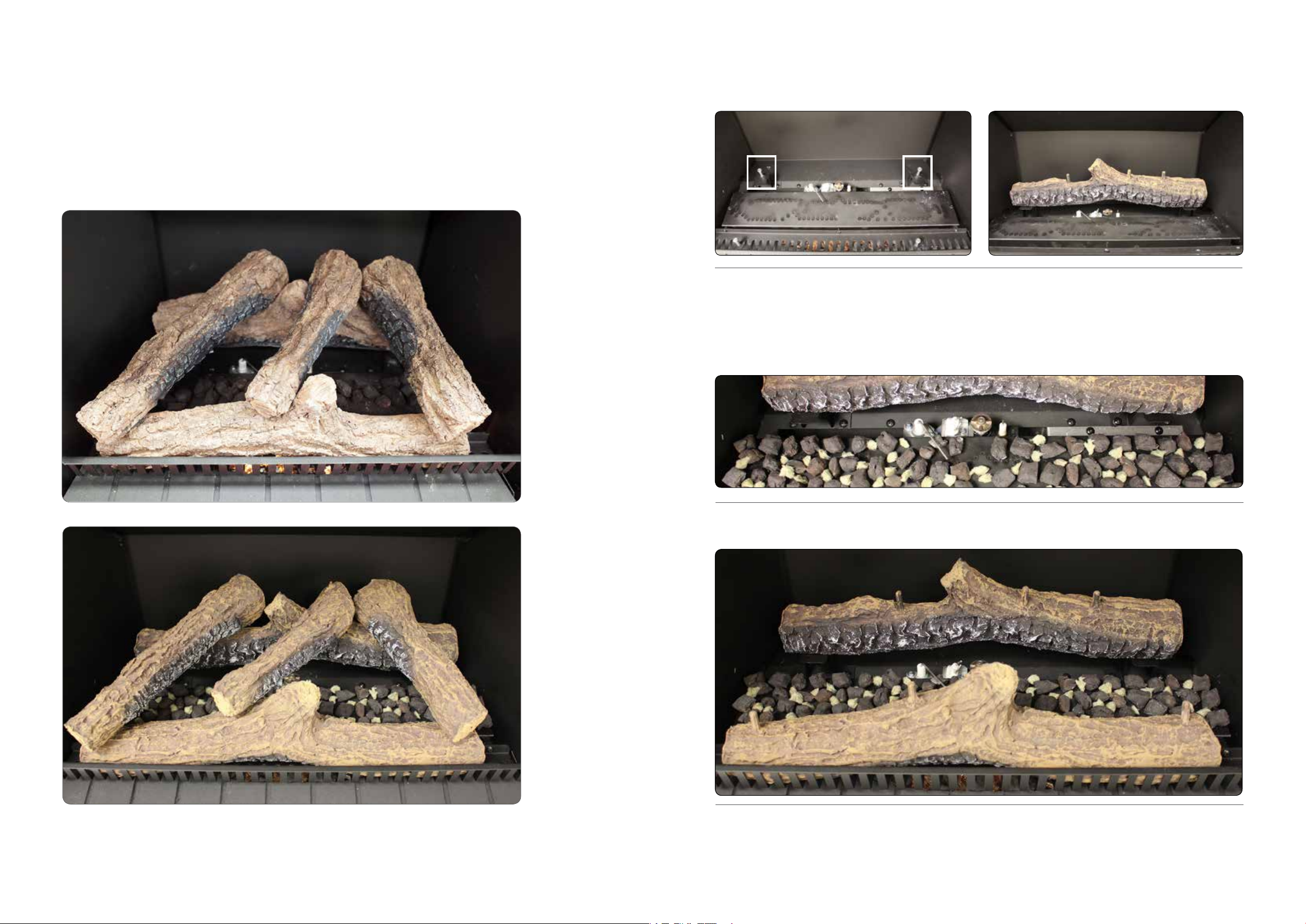
Log set installation
The log set is packaged separately and consists of five log pieces. Use extreme care
when handling the logs, they are made from fragile material and will damage easily.
While the log set for the Ember 600 and 700 are different (Ember 600 is smaller),
the installation steps are the same—the 700 has been used in these instructions.
Ember 600
44
1
4
2
3
Step 1: Back log
Place the back log onto the two log location brackets at the back of the burner. The charred side
faces to the front.
Step 2: Adding the granules and rockwool
Place, DO NOT POUR, the granules, ensuring even coverage around the burner ports (so as not to
cause blockages). For the 700 you will need both granule packs, for the 600 it’s about a bag and
three quarters. Pinch and roll the rockwool into pea-sized balls (600 ≈ 35, 700 ≈ 50) and place inbetween the granules. These can go over the burner ports as the material is designed for the flame
to penetrate through the ceramic fibres to enhance the flame picture and produce a glow effect
.
Ember 700
3
4 4 4
1
2
3
Step 3: Front log
Add the front log onto the two log locating pins inside the grill. It should sit securely into the gap.
Before adding the log set make sure the vermiculite and glass packets have been added into the
burn media tray (refer previous page), and that it has been secured back in place. All the logs
have locating pins making it possible to only fit one way onto the burner.
22 | Ember Installation Guide: 12890-B 02-18
Step 4: Top three logs
Add the three top logs onto the locating pins of the back and front logs—refer photos on
previous page. Underneath each log is a hole (front position) and a slot (back position).
Ember Installation Guide: 12890-B 02-18 | 23
Page 13
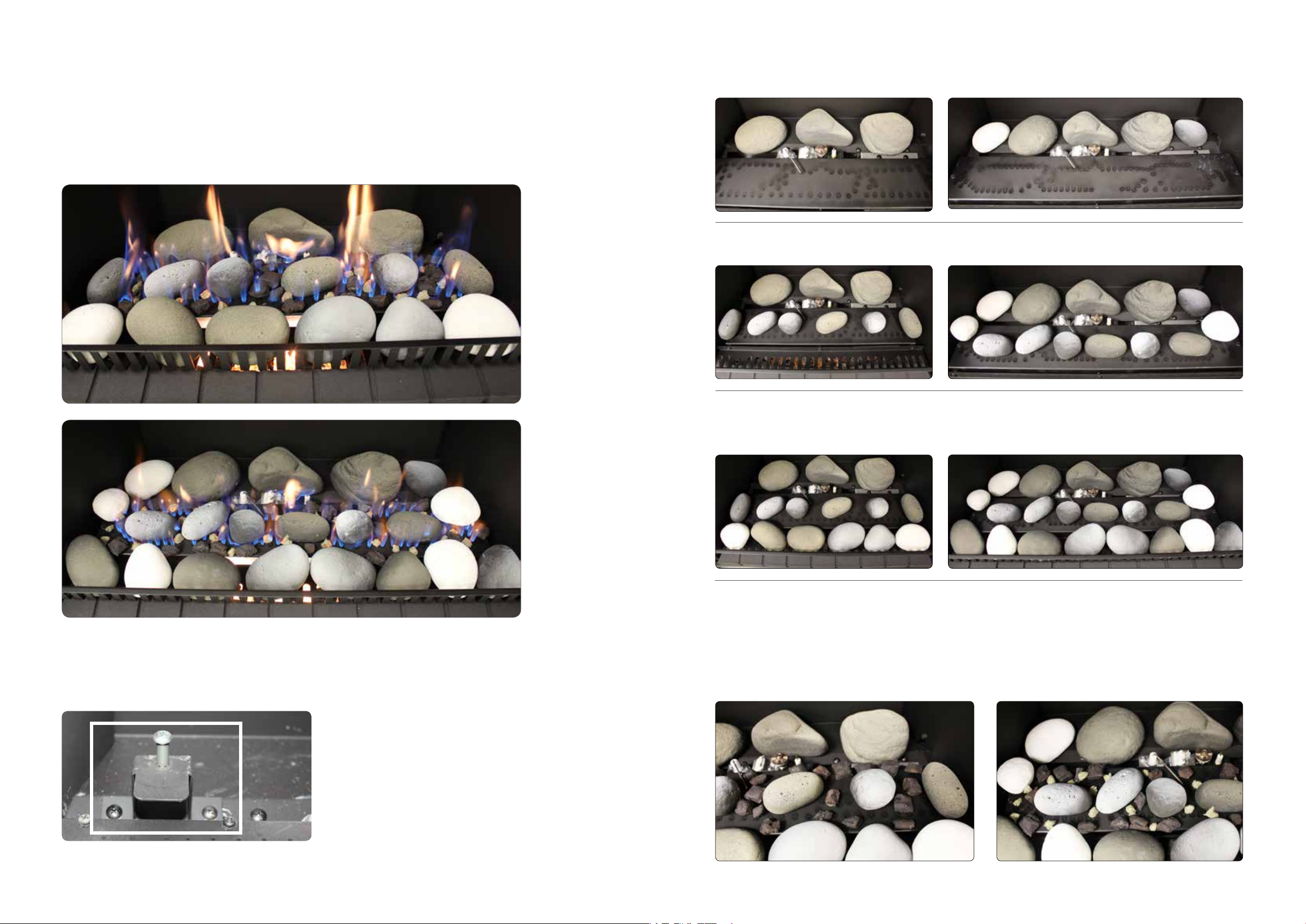
Stone set installation
Step 1: Back row of stones
Place the back row of stones as shown.
The stone set is packaged separately. Use extreme care when handling the stones,
they are made from fragile material and will damage easily. While the stone sets
for the Ember 600 and 700 are different (Ember 600 has six less stones), the
installation steps are the same. Refer to p. 20 for the correct installation order.
Ember 600
1
2
3
4
Ember 700
Ember 600 Ember 700
Step 2: Middle row of stones
Place the middle row of stones BETWEEN the burner ports as shown.
Ember 600 Ember 700
Step 3: Front row of stones
Add the front row of stones inside the grill. A few of these will be angled slightly to cover the
front of the burner bed.
1
2
3
Before adding the stone set make sure the vermiculite and glass packets have been added into
the burn media tray (refer p.21), and that it has been secured back in place. Also remove the two
back log locating pins and bracket (not needed for the stone set)—replace the black screws
holding the bracket back into the burner.
Ember 600 Ember 700
Step 4: Adding the granules and rockwool
Place, DO NOT POUR, the granules, ensuring even coverage around the burner ports (so as not to
cause blockages). You will use approx. one bag of granules for both models (a bag will be leftover).
Pinch and roll the rockwool into pea-sized balls (600 ≈ 20, 700 ≈ 30) and place in-between the
granules. These can go over the burner ports as the material is designed for the flame to penetrate
through the ceramic fibres to enhance the flame picture and produce a glow effect.
Back log location pin and bracket
24 | Ember Installation Guide: 12890-B 02-18
Ember Installation Guide: 12890-B 02-18 | 25
Page 14
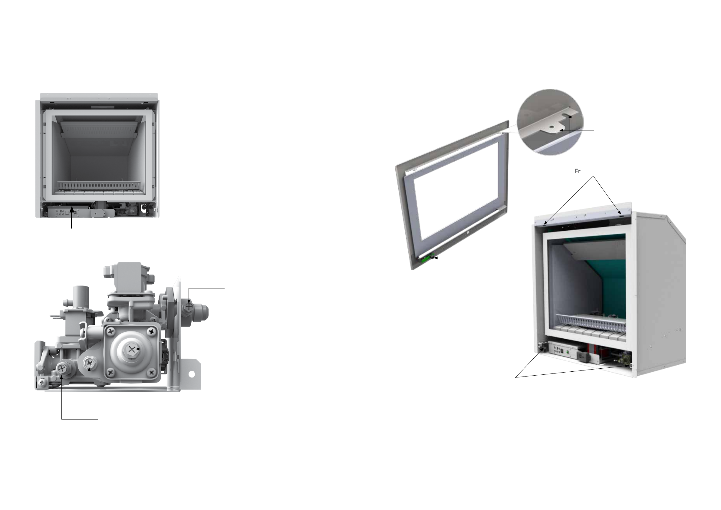
Commissioning
Installing the frame
The gas pressures must be checked against those printed on the data plate of the
appliance. The pressures are factory set and may not require adjustment. When
checking the operating pressures the combustion chamber glass must be on.
The commissioning sheet, and a 19 mm small
spanner for the gas connection, is located in a
plastic pouch inside the unit on top of the PCB
cover.
Follow the commissioning instructions to complete
the gas pressure checks. When commissioning is
complete check for full and correct operation of the
appliance, and return the commissioning sheet to
its plastic pouch.
Commissioning sheet (and small 19 mm
spanner) located on top of the PCB cover
Easy four stage process, which will be the same regardless of frame type, for
example 3-sided frame, 4-sided frame, or the 700 masonry frame.
U-shaped fixings (1 of 3) for
screwing the frame in place
Frame hanger (1 of 2)
Frame slots
Pilot pressure test point
Main burner pressure test point screw
CAT5 connection
Inlet pressure test point screw
Pilot pressure adjustment screw
Lower screw position
1. Position the frame assembly in front of the engine and connect the CAT5 cable to the frame.
This connects the push button control panel to the engine’s box.
2. Slide the two top frame hangers into the corresponding frame slots on the Ember engine
and push the lower section into the recess of the engine.
26 | Ember Installation Guide: 12890-B 02-18
3. Secure the top section in place, using the screws provided, via the three U-shaped fixing
positions on the frame.
4. Secure the lower section of the frame in place using the two bottom side screws.
Ember Installation Guide: 12890-B 02-18 | 27
Page 15
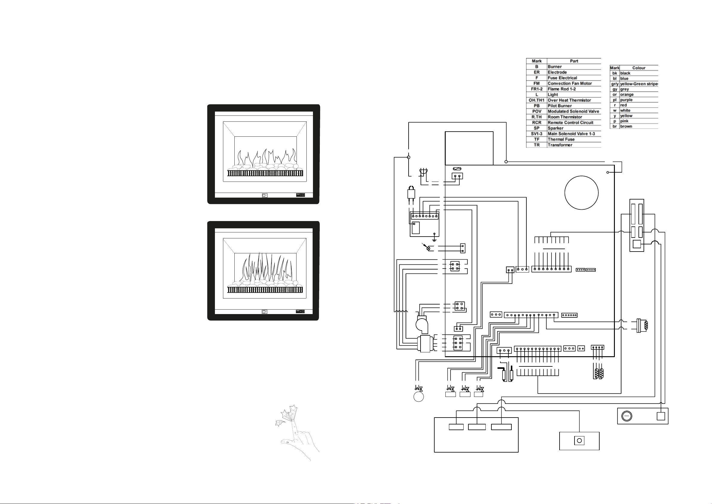
Test operation and lighting sequence
It may take approximately two hours of operation for the burn media to achieve their full
flame pattern and glow. During the initial burning in period, some smoke and smell may
be experienced. The appliance should run on the high setting in a well ventilated room
until these dissipate. It is important to check the flame pattern during this time.
Abnormal flame pattern
Abnormal flame performance and/or pattern can
indicate a problem with your fire, such as blocked
gas injectors, or that the burn media has shifted.
There are some warning signs that could indicate
a problem.
- Unusual smell from the appliance
- Continued difficulty or delay in establishing a
flame
- Flame appears either very short or very long
Normal flame pattern
- Flame only burns part way across the burner
- Severe soot building up on the inside of the
glass door
Important
It is the responsibility of the installer to check that
under normal conditions of the appliance, all flue
gases are exhausted to the outside atmosphere,
and that there is no spillage of combustion gases
into the room.
If the appliance cannot be made to perform
correctly please contact Rinnai.
Abnormal flame pattern
Wiring diagram (part of commissioning)
gr/y
AC 230-240V
gr/y
ER
w w
1 2 3 4 5 6 7 8
SP
Light Only for
RDV600-700
gr/y
p w
FM
TR
5A
F
1
br
2
bl
gy
or
bl
r
L
r
bl
bk
br
bl
w
HI
bl
COM
w
LO
y
pl
gy
or
y
or
2
1
3
2
1
bl w
N
2
1
4
3
2
1
3
1 2
6
5
y w
w y
1 2
13 12 11 10 9 8 7 6 5 4 3 2 1
12 11 10 9 8 7 6 5 4 3 2 1
3 2 1
r bl
bl bl r
FR2 FR1
1 2 3
r bl bl
1 2 3 4 5 6 7 8 9
OH.TH1
gr/y
4 3 2 1
w w bk bk
R.TH
TF
w
w
Installation checklist and customer handover
Complete the installation checklist in the customer operation guide, and
make sure you leave the guide with the customer. Add a touch of magic
by taking the time to explain to the customer about the use and care of
the unit, and that they understand the instructions.
28 | Ember Installation Guide: 12890-B 02-18
POV
SV 3 SV 2
SV 1
CONTROL DISPLAY UNIT
ON
OFF
ON/OFF DISPLAY UNIT
RCR
WIRING DIAGRAM UNI CONTROL MODEL 3
1 Burner
Issue B
Ember Installation Guide: 12890-B 02-18 | 29
Page 16
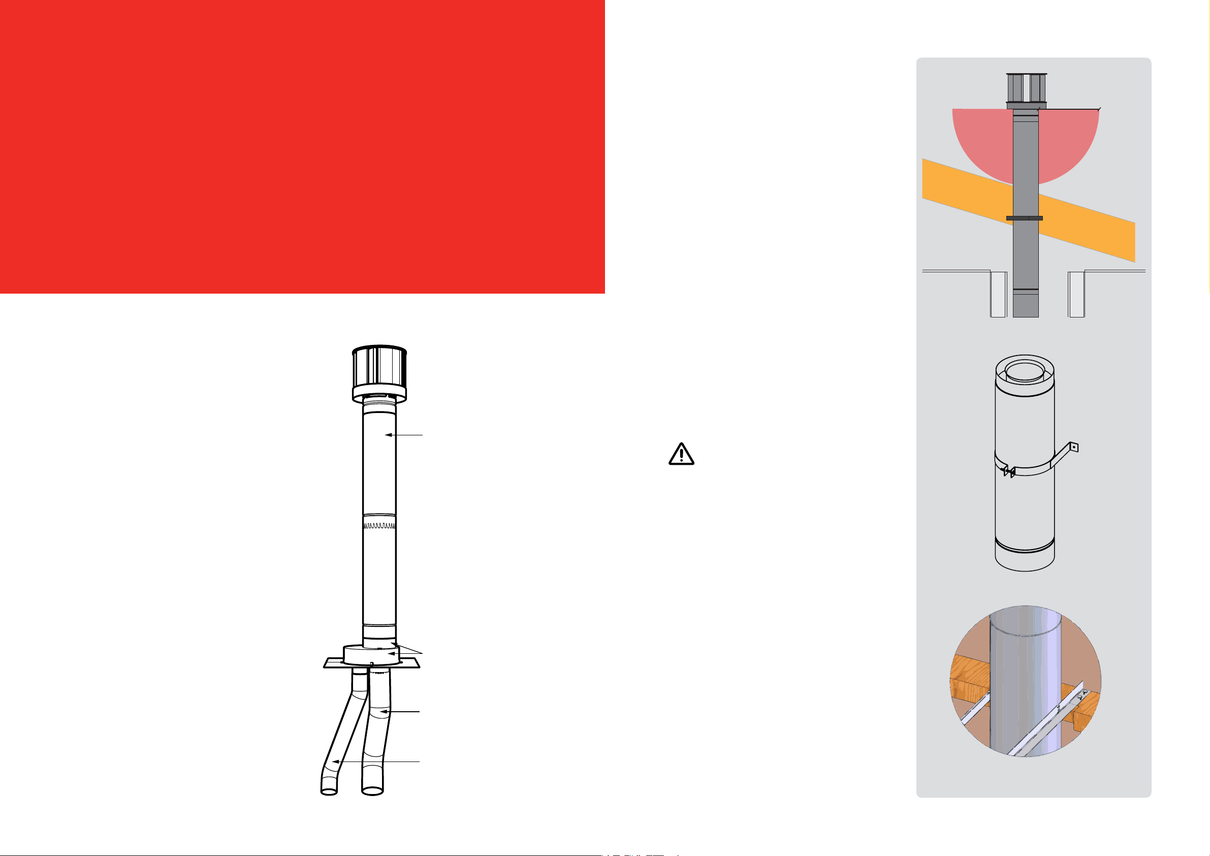
Ember ueing
WARNING
Flue terminal locations
Flue terminals must be compliant with the flue
terminal locations shown in AS/NZS 5601.1.
Every gas re requires a ue system that will draw eectively and clear
ue products safely under all potential wind and climatic conditions. It
is the responsibility of the installer to ensure the appliance is provided
with an eective ue.
Some guidelines to assist with ue design are detailed below. These
must be read and modied as necessary depending on the installation.
The Ember must be installed with an approved ue system, approved
components are shown in this guide.
General ueing guidelines
Flue clearance to combustibles
Flueing for the Rinnai Ember, depending on
the installation is comprised of three main
components:
- flexible aluminium flues that come straight
off the fire
- galvanised steel colinear to coaxial adaptor
(stainless steel inner)
- galvanised steel outer, aluminium inner
coaxial flue
These all have slightly different clearances to
combustibles.
Flue cowl clearance
To ensure products of combustion are
cleared, adequate clearance from the building
is required.
The flue cowl should have a 500 mm clearance
from any part of the building. This also applies
to steeped and pitched roofs where the flue
cowl should be 500 mm clear of the ridge
line. An adequate flow of fresh air must exist
around the flue cowl following installation.
Coaxial flue
10 mm from the outer flue to
a combustible surface to allow
for expansion and contraction
of the outer flue components.
Ember adaptor (transition)
25 mm clearance to a
combustible surface―the
underside of the adaptor has
zero clearance and can be
installed straight into wooden
support joists.
Ø 100 mm exhaust flexi flue
Requires a 50 mm clearance
to combustibles.
The flue cannot terminate under a floor or in a
roof space.
Self-supporting flue
The weight of the flue system should not be
supported by the appliance—it should be selfsupporting.
Supporting the flue is usually completed
during the framing stage with flue supports
or straps within the cavity. Wall straps have
been included in the Rinnai vertical flue kits.
Elbow straps are also available as a separate
component to prevent excess weight on the
flue elbow.
Horizontal runs of flue pipe
Horizontal runs of flue pipe must be
supported to prevent any downward sags.
Horizontal pipe sections should be supported
every 1.2 m. Wall straps can be used for this
purpose.
The horizontal run of flue pipe must
have a 20 mm rise for every 1 m of run
towards the flue termination, NEVER
allow the flue pipe to run downwards
towards the horizontal flue terminal.
A downward slope can trap heat and
become a fire hazard.
Shared flues
Gas appliances must not be connected to
a chimney or flue serving a separate fuel
burning appliance.
Flashings
Flashings are not included with the Ember
flue kits, these must be specified. The only
exception is the flashing kit provided in the
horizontal flue kit.
500 mm to
nearest part
of roof
Min. clearance of 500 mm to the nearest part of the roof
Self-supporting coaxial flue using a wall strap
Minimum clearances are shown in
AS/NZS 5601.1.
30 | Ember Installation Guide: 12890-B 02-18
Ø 75 mm intake flexi flue
Requires a 50 mm clearance
to combustibles.
Self-supporting flue using straps within the cavity
Ember Installation Guide: 12890-B 02-18 | 31
Page 17
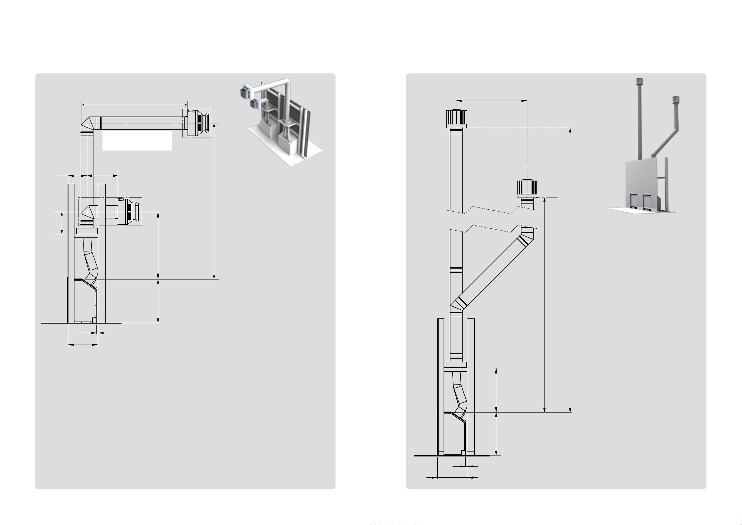
Flueing options
Flueing options
Horizontal terminations (mock chimney)
Dimensions are in mm unless otherwise stated
255
295
4 3
Important
The horizontal flue length must
not be greater than the vertical.
3
245-410*
1
20
400
2 m max.
Flue cowl slides depending on wall thickness
2
900 min.
590
Unit height
5 & 6
Flue components
1. Ember adaptor (R3653)
Refer p. 30 for clearance to
combustible information for
2 m max.
the Ember adaptor.
2. Mock chimney horizontal
flue kit (R3654)
3. Flue pipe(s) 150-1000 mm
4. Flue elbow 90 ° (R3643)
Max. number of 90 ° bends
= one.
5. Horizontal flashing kit
(R3646)
6. Horizontal wall terminal
(R3650)
Vertical terminations (mock chimney)
Dimensions are in mm unless otherwise stated
2 m max.
4
2
4
2
Flue components
3
2
2
10 m max.
3
8 m max.
2
1
1. Ember adaptor (R3653)
Refer p. 30 for clearance to
combustible information for the
Ember adaptor. N.B: Can’t be
more than 600 mm maximum, as
shown, due to the heat from the
colinear flexi flues.
Flue pipe(s) 150-1200 mm or
Flue extension(s)
If doing a straight short vertical
flue (no bends) for a single
storey dwelling the mock
chimney vertical flue kit 3.6 m
can be used (R3665).
Important notes
• For the horizontal flue terminal to comply with the required flue clearances, and to fit
under a 2.4 m eave, the maximum the fire can be installed above the floor is 400 mm.
Check clearances first before installation.
• The horizontal run of flue pipe must have a 20 mm rise for every 1 m towards the flue
termination. NEVER allow the flue pipe to run downwards towards the flue terminal. A
downwards slope can trap heat and become a fire hazard.
• The horizontal flue length must not be greater than the vertical.
32 | Ember Installation Guide: 12890-B 02-18
2. Flue elbow 45 ° (R3642)
Maximum number of 45 ° bends
= 2
600 max.
3. Roof cowl (R3651)
590
Unit height
20
400
Ember Installation Guide: 12890-B 02-18 | 33
Page 18
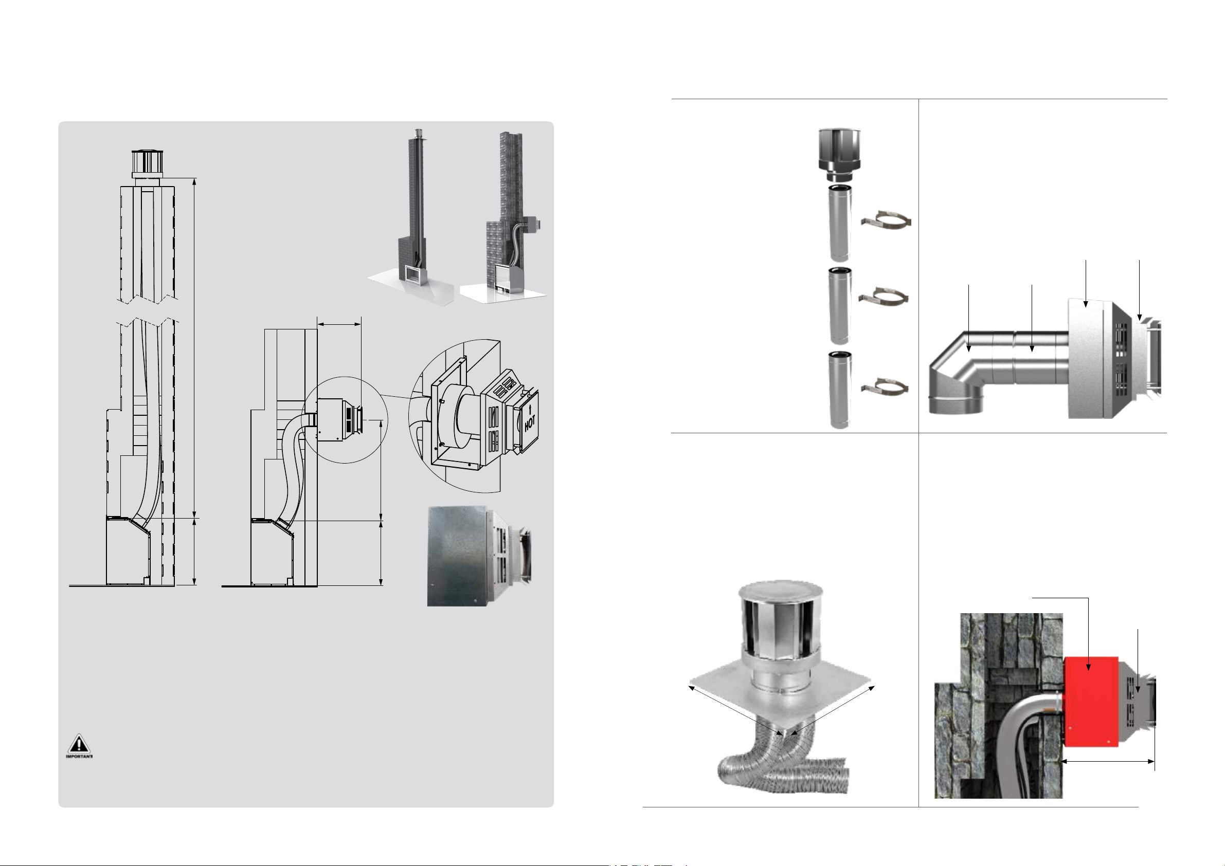
Unit height
Flueing options
Unit height
Vertical and horizontal termination (masonry only)
Flue kits and components
Dimensions are in mm unless otherwise stated
8 m maximum
400
Mock chimney vertical flue kit 3.6 m
Code: R3665
Coaxial vertical flue kit
that attaches to the Ember
Adaptor.
Kit includes; high wind roof
cowl, flue pipes 1200 mm x 3,
wall straps x 3.
If longer flueing is required,
order additional flue pipes.
Mock chimney horizontal flue kit
Code: R3654
Coaxial horizontal flue kit that attaches to the
Ember Adaptor.
If longer flueing is required order additional flue
pipes.
90 ° bend
Horiz.
flashing
kit
300 mm
flue pipe
Horiz.wall
terminal
900 min.
1200 max.
590
590
Vertical termination flue component
Masonry chimney flexi vertical flue kit (R3652)—actual chimney size needs to be at least
200 x 200 mm for the flexi flues to fit down the chimney.
Horizontal termination flue components
1. Ember adaptor (R3653), stretches out to 1.2 m
2. Masonry horizontal flue box (R2449)
3. Horizontal wall terminal (R3650)
Masonry chimney flexi vertical flue kit
Code: R3652
For installation into a masonry fireplace. Allows
the fire to perform more effectively by achieving a
better draw. Extends out to 8 m.
Kit includes; flue cowl, chimney flashing plate,
intake flexi Ø 75 mm (LHS), exhaust flexi Ø100 mm
(RHS).
455 mm
455 mm
Masonry horizontal flue box
Code: R2449
Horizontal flue box that joins the Ember
adaptor to the horizontal wall terminal. Used in
installations where the chimney has been capped
off. Refer previous page for detail drawing.
Kit includes; masonry chimney plate, and masonry
box.
Horizontal flue
box (R2449)
Horizontal
wall terminal
(R3650)
These flueing options are available for non-combustible openings only.
34 | Ember Installation Guide: 12890-B 02-18
400 mm
Ember Installation Guide: 12890-B 02-18 | 35
Page 19
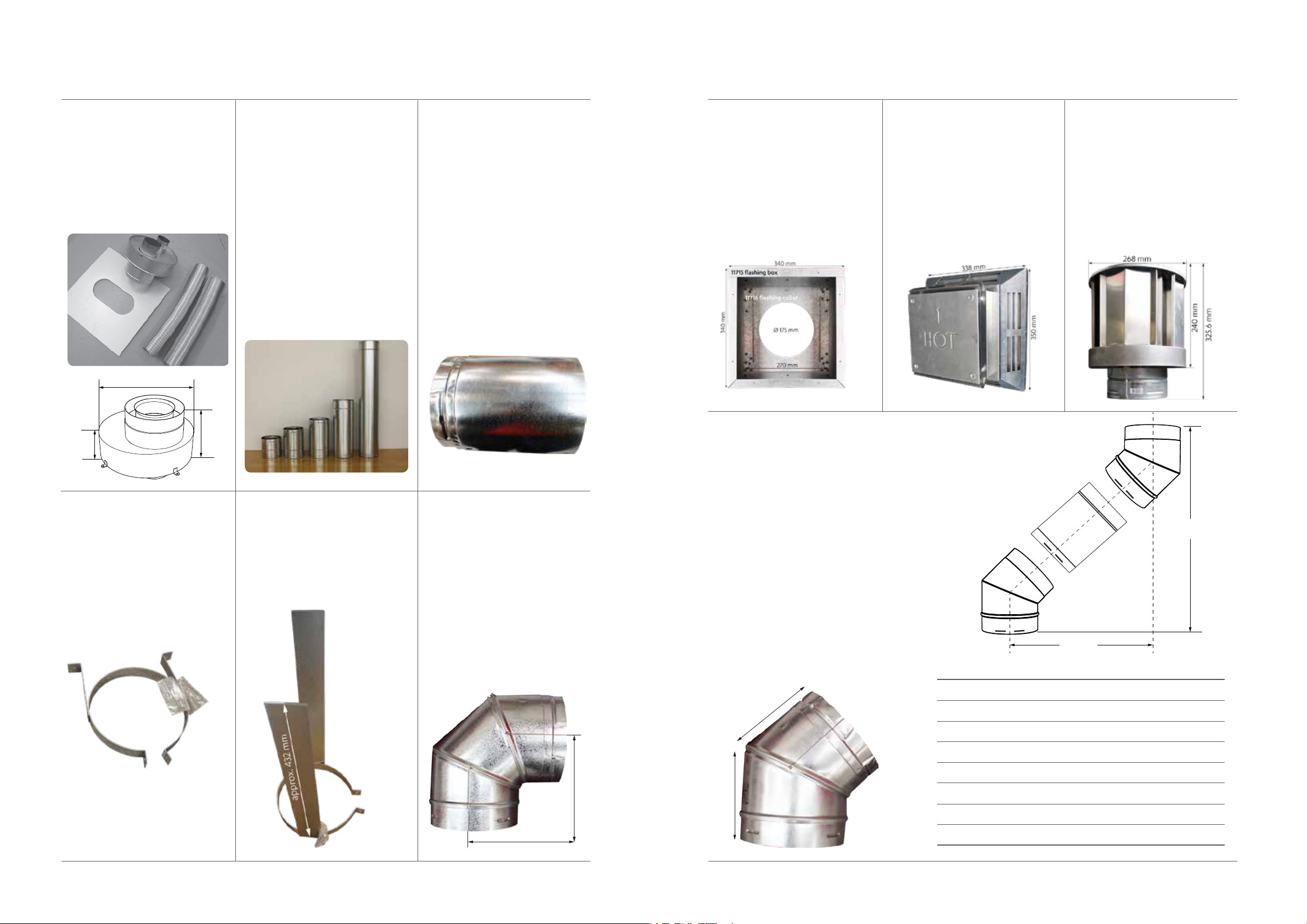
Rise
Offset
Flue kits and components
Ember flue adaptor
Code: R3653
Colinear to coaxial adaptor.
Contains; adaptor, locating plate
(455 x 455 mm), Ø 75 mm and
Ø 100 mm flexi flues, and four
flue clamps. Stretches out to
1.2 m.
280 mm
Flue pipes
150 mm: R3630
230 mm: R3631
300 mm: R3632
450 mm: R3633
600 mm: R3634
900 mm: R3635
1200 mm: R3636
Pipe used to construct
horizontal and vertical flueing.
Cannot be cut to size. Once
joined nominal length reduces
approx. 35 mm.
Inner - aluminium Ø 100 mm
Outer - galvanised steel Ø 170 mm
Flue extension
75-175 mm: R3638
75-360 mm: R3639
Used for extended straight
lengths of flue.
Available in two lengths
extending to 175 mm or
360 mm.
Inner - aluminium Ø 100 mm
Outer - galvanised steel Ø 170 mm
Horizontal flashing kit
Code: R3646
Flashing components used
to join the internal flue to the
outside flue—to provide a
weathertight seal in horizontal
flue installations. Refer
horizontal wall terminal for
installed dimensions. Box depth
is 100 mm.
Horizontal wall terminal
Code: R3650
Aluminium flue terminal
required for all horizontal
terminations.
Depth with horizontal flashing
kit installed—252 mm.
Roof cowl
Code: R3651
Aluminium flue terminal
required for all vertical flue
installations—part of all vertical
flue kits.
78 mm
165 mm
Wall flue strap
Code: R3647
Adjustable strap used to add
lateral support to the flue.
Provides a 50-200 mm clearance
to combustible walls.
Elbow flue strap
Code: R3644
Flue support for elbows and
offsets.
Flue elbow 90 °
Code: R3643
Used to facilitate between
vertical and horizontal flueing.
Elbow swivels 360 ° at base.
Once joined effective length
reduces 35 mm to approx.
130 mm.
Inner - aluminium Ø 100 mm
Outer - galvanised steel Ø 170 mm
Flue elbow 45 ° (x2)
Code: R3642
Offsets obstructions.
Elbow swivels 360 ° at base.
Once joined effective length
reduces 35 mm to approx.
73 mm.
Inner - aluminium Ø 100 mm
Outer - galvanised steel Ø 170 mm
108 mm
Flue pipe (length and code) Offset Rise
None (bend to bend) N/A 124 mm 340 mm
150 mm R3630 203 mm 419 mm
230 mm R3631 257 mm 473 mm
36 | Ember Installation Guide: 12890-B 02-18
165 mm
165 mm
108 mm
300 mm R3632 311 mm 527 mm
450 mm R3633 417 mm 633 mm
600 mm R3634 524 mm 740 mm
900 mm R3635 737 mm 953 mm
1200 mm R3636 949 mm 1165 mm
Ember Installation Guide: 12890-B 02-18 | 37
Page 20

Page 21
Rinnai.co.nz
Experience our innovation
0800 746 624
http://www.youtube.com/rinnainz
http://www.facebook.com/rinnainz
Ember Installation Guide: 12890-B 02-18
 Loading...