

Page 1
These instructions are a
guide to assembling
and using the Alfresco
barbecue.
Please read carefully and retain
for future reference.
Only to be used outdoors.
Illustration may vary from barbecue
contained in carton.
FOR YOUR SAFETY.
1. Do not store or use
petrol or other flammable
vapours and liquids in the
vicinity of this or any other
appliance.
2. A gas cylinder not connected
for use must not be stored
in the vicinity of this or any
other appliance.
FOR YOUR SAFETY.
IF YOU SMELL GAS:
1. Shut off gas to the appliance,
if possible.
2. Extinguish any open flame.
3. Open hood.
4. If odour continues,
immediately call your gas
supplier or fire department.
Operating and assembly instructions
Portable Gas Barbecue
Page 2
General 2
Safety 3
Outdoor Areas 4
Pre-Assembly 5
Assembly 6-11
Inspection 12-13
Accessory Assembly 13
Operation 14-16
Fault Finding 17
Maintenance 18-20
Parts Diagram and Lists 22-23
TABLE OF CONTENTS
Barbecues must be used in accordance with the installation
requirements of your local gas supply authority, and the
appropriate installation standard AS5601/AG601.
Barbecues for use with bottled gas are labelled
‘Universal
LPG’. Barbecues for use with natural gas are labelled ‘Natural
Gas’ and must be installed by a qualified person. Check the
gas type sticker attached to the barbecue. Check that the label
matches the gas type to be used.
GAS INSTALLATION CODES
FAILURE TO COMPLY WITH THESE
INSTRUCTIONS COULD RESULT IN A
FIRE OR EXPLOSION WHICH COULD
CAUSE SERIOUS BODILY INJURY,
DEATH OR PROPERTY DAMAGE.
ACCESSIBLE PARTS MAY BE VERY HOT.
KEEP YOUNG CHILDREN AWAY.
ANY MODIFICATION OF THIS
APPLIANCE MAY BE DANGEROUS.
DO NOT MOVE THIS APPLIANCE
DURING USE.
TURN OFF THE GAS SUPPLY AT THE
GAS CYLINDER AFTER USE.
READ THE INSTRUCTIONS BEFORE
USING THE APPLIANCE.
PARTS SEALED BY THE
MANUFACTURER MUST NOT BE
MANIPULATED.
THIS BARBECUE IS ONLY TO BE USED
OUTDOORS.
NEVER OPERATE THIS BARBECUE
WITHOUT A REGULATOR.
Appliance specifications can be found on the data label
attached to the rear panel of the barbecue body.
SPECIFICATIONS
GENERAL
2
2
Purchased from
Date purchased
Serial No.
NOTE:
Sales docket must be kept as proof of purchase date.
FOR CUSTOMER REFERENCE
(Record and file in a safe place)
This barbecue is also certified for use on natural gas. It must be
converted and installed by a qualified person if not provided in
the correct condition for use on natural gas. Contact your place
of purchase for advice in relation to using your barbecue on
natural gas if not already provided in natural gas specification.
NATURAL GAS INSTALLATION
The regulator and hose assembly supplied with the barbecue is
suitable for use with bottled gas – POL connection.
A gas regulator adjusted to have an outlet pressure of 2.75
kPa is supplied for connection to the gas cylinder. The regulator
and hose assembly supplied with the appliance must be used.
Replacement regulator and hose assemblies must be those
specified by the appliance manufacturer.
When connecting the hose and regulator assembly to the
gas cylinder, take care to avoid unnecessary twisting of the
flexible hose. After the assembly has been secured, turn on the
gas and check for leaks by brushing a soap and water solution
over all visible and accessible gas line connections. The presence
of bubbles will indicate a gas escape. DO NOT TEST FOR GAS
ESCAPES WITH AN OPEN FLAME.
If you are unable to correct the leak by tightening the
connection, turn off the gas and contact your place of purchase
immediately.
Always ensure the appliance is kept away from flammable
materials and the gas cylinder clear of any heat source.
When changing over from an empty gas cylinder to a full
one, make sure this procedure is carried out in a flame free
atmosphere.
Inspect the gas hose when replacing the gas cylinder or
once a year whichever is more frequent. If the hose is cracked,
cut, abraded or damaged in any way, the appliance must not be
operated. The hose must be replaced if damaged or when
statutory conditions require it. Contact your place of purchase
if uncertain.
The POL fitting of the hose and regulator should be
disconnected from the gas cylinder valve when the outdoor
appliance is not in use.
HOSE AND REGULATOR SAFETY
Height – hood closed 1235 mm, hood open 1605 mm
Width – 1840 mm
Depth – hood closed 660 mm, hood open 785 mm
Openings at the rear and sides of the appliance provide air
for combustion, and must not be obstructed.
Minimum clearances from combustible materials must be
maintained: top and rear – 800 mm, sides – 250 mm, bottom of
firebox – 300 mm
(inbuilt model).
DIMENSIONS AND CLEARANCES
5
/8"-18 UNF (3/8" SAE FLARE).
HOSE CONNECTIONS
Page 3
SAFETY
3
3
FOR YOUR SAFETY:
DO NOT STORE OR USE PETROL OR
OTHER FLAMMABLE VAPOURS AND
LIQUIDS IN THE VICINITY OF THIS OR
ANY OTHER APPLIANCE.
DO NOT STORE EMPTY OR FULL SPARE
GAS CYLINDERS IN STORAGE
COMPARTMENT OR NEAR THIS OR ANY
OTHER APPLIANCE.
KEEP THE GAS HOSE AWAY FROM HOT
SURFACES. PROTECT GAS HOSE FROM
DRIPPING GREASE.
AVOID UNNECESSARY TWISTING OF
HOSE. VISUALLY INSPECT HOSE PRIOR
TO EACH USE FOR CUTS, CRACKS,
EXCESSIVE WEAR OR OTHER DAMAGE.
REPLACE HOSE, IF NECESSARY.
NEVER TEST FOR GAS LEAKS WITH A LIT
MATCH OR OPEN FLAME.
NEVER LIGHT BARBECUE WITH HOOD
CLOSED.
NEVER LEAN OVER COOKING
SURFACE WHILE LIGHTING BARBECUE.
USE GOOD QUALITY INSULATED OVEN
MITTS WHEN OPERATING BARBECUE.
NEVER ALTER OR MODIFY THE
REGULATOR OR GAS SUPPLY ASSEMBLY.
THIS BARBECUE MUST NOT BE USED
INDOORS.
DANGER – IF YOU SMELL OR HEAR THE
HISS OF ESCAPING GAS FROM THE GAS
CYLINDER:
KEEP CLEAR OF THE GAS CYLINDER.
DO NOT ATTEMPT TO CORRECT THE
PROBLEM YOURSELF.
CALL YOUR FIRE DEPARTMENT
(DO NOT MAKE THE CALL FROM
ANYWHERE NEAR THE GAS CYLINDER –
YOUR TELEPHONE IS AN ELECTRICAL
DEVICE, AND COULD PRODUCE A SPARK).
READ CAREFULLY BEFORE
ASSEMBLING AND OPERATING
YOUR BARBECUE.
NEVER CONNECT AN UNREGULATED
GAS CYLINDER TO YOUR BARBECUE.
NEVER STORE YOUR GAS
CYLINDER INDOORS.
FOR STORAGE AND CYLINDER
EXCHANGE, DISCONNECT HOSE AT
THE CYLINDER ONLY – DO NOT
DISCONNECT HOSE FROM
THE APPLIANCE.
DO NOT use your barbecue in garages, porches, breezeways,
sheds or other enclosed areas. Your barbecue is to be used
OUTDOORS ONLY. Refer to page 5. The barbecue is not
intended to be installed in or on recreational vehicles
and/or boats and should not be placed under any surface
that will burn. Do not obstruct the flow of combustion and
ventilation air around the barbecue while in use.
LOCATION OF YOUR BARBECUE
Keep children away from barbecue during use and until
barbecue has cooled after you are finished. Do not allow
children to operate barbecue, or to swing on handle.
PROTECT CHILDREN
NEVER TEST FOR LEAKS WITH AN OPEN FLAME.
Prior to first use, and at the beginning of each new season
(or, if using bottled gas, whenever gas cylinder is changed), you
must check for gas leaks.
Follow these steps:
1. Make soap solution by mixing one part liquid detergent
and one part water.
2. Turn burner control(s) to
‘OFF’, then turn on gas at
source.
3. Apply the soap solution to all visible and accessible
gas connections. Bubbles will appear in the soap
solution if connections are not properly sealed.
Tighten or rectify as necessary.
4. If you have a gas leak you cannot rectify, turn off the
gas at the source, disconnect hose from barbecue and
immediately contact your place of purchase for
assistance.
Refer to page back cover.
CHECKING FOR GAS LEAKS
The gas cylinder should be filled by a reputable gas dealer,
or exchanged at a reputable cylinder exchange outlet. Gas
cylinders should be visually inspected and requalified
periodically.
Always keep gas cylinder in an upright position.
Always close the cylinder valve when the barbecue is not in use.
Do not subject gas cylinder to excessive heat.
If you store your barbecue indoors, ALWAYS disconnect
and remove gas cylinder FIRST, and store gas cylinder safely
outside. Gas cylinders must be stored outdoors in a well
ventilated area out of reach of children, and must not be
stored in a building, garage or any other enclosed area.
This is a low pressure barbecue and must only be used with
the hose and regulator supplied.
Your barbecue is designed for use with a 9 kg gas
cylinder. Ensure gas cylinder conforms to Australian
standards.
DO NOT CONNECT YOUR BARBECUE TO A GAS
CYLINDER LESS THAN OR EXCEEDING THIS CAPACITY.
GAS CYLINDER USE AND SAFETY
IF YOU SMELL GAS:
1. SHUT OFF GAS TO THE APPLIANCE
AT ITS SOURCE, IF POSSIBLE.
2. EXTINGUISH ANY OPEN FLAME.
3. OPEN HOOD.
4. PERFORM GAS LEAK CHECK
PROCEDURE.
5. IF ODOUR CONTINUES,
IMMEDIATELY CALL YOUR GAS
SUPPLIER OR FIRE DEPARTMENT.
Page 4
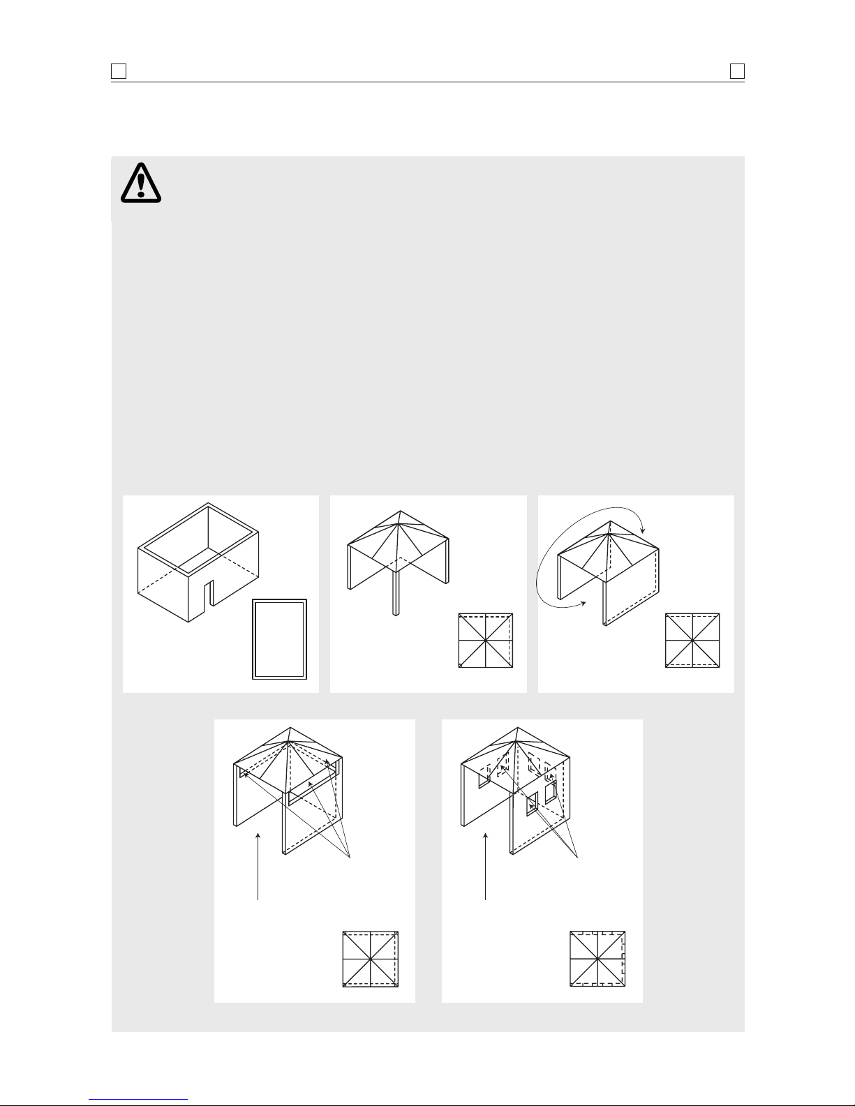
The following diagrams are examples of outdoor areas.
These same principles apply to canopy or shaded cloth areas.
THIS APPLIANCE SHALL ONLY BE USED IN AN ABOVE GROUND OPEN AIR SITUATION WITH NATURAL
VENTILATION, WITHOUT STAGNANT AREAS, WHERE GAS LEAKAGE AND PRODUCTS OF COMBUSTION
ARE RAPIDLY DISPERSED BY WIND AND NATURAL CONVECTION.
ANY ENCLOSURE IN WHICH THE APPLIANCE IS USED SHALL COMPLY WITH ONE OF THE FOLLOWING:
OUTDOOR AREAS
4
4
• AN ENCLOSURE WITH WALLS
ON ALL SIDES, BUT AT LEAST
ONE PERMANENT OPENING AT
GROUND LEVEL AND NO
OVERHEAD COVER
• WITHIN A PARTIAL
ENCLOSURE THAT INCLUDES
AN OVERHEAD COVER AND NO
MORE THAN TWO WALLS
• WITHIN A PARTIAL
ENCLOSURE THAT INCLUDES
AN OVERHEAD COVER AND
MORE THAN TWO WALLS, THE
FOLLOWING SHALL APPLY:
(i) AT LEAST 25% OF THE TOTAL
WALL AREA IS COMPLETELY
OPEN: AND
(ii) AT LEAST 30% OF THE
REMAINING WALL AREA IS
OPEN AND UNRESTRICTED
• IN THE CASE OF BALCONIES,
AT LEAST 20% OF THE TOTAL
OF THE SIDE, BACK AND FRONT
WALL AREAS SHALL BE AND
REMAIN OPEN AND
UNRESTRICTED
• DO NOT USE YOUR BARBECUE
IN GARAGES, PORCHES,
BREEZEWAYS, SHEDS OR OTHER
ENCLOSED AREAS.
YOUR BARBECUE IS TO BE
USED OUTDOORS ONLY.
Refer below
• THE BARBECUE IS NOT
INTENDED TO BE INSTALLED IN
OR USED ON RECREATIONAL
VEHICLES AND/OR BOATS AND
SHOULD NOT BE PLACED
ADJACENT TO OR UNDER ANY
SURFACE THAT WILL BURN
• DO NOT OBSTRUCT THE FLOW
OF COMBUSTION AND
VENTILATION AIR AROUND
THE BARBECUE HOUSING
WHILST IN USE.
Both ends
open
30% or more in total
of the remaining wall
area is open and
unrestricted
30% or more in total
of the remaining wall
area is open and
unrestricted
Open side at
least 25% of
total wall area
Open side at
least 25% of
total wall area
Page 5
PRE-ASSEMBLY
5
5
Before attempting to assemble your barbecue, check
that all the necessary parts have been included using the
parts list opposite. Inspect barbecue and trolley parts as
you proceed.
Contact your place of purchase for assistance
regarding replacement of any damaged or missing
parts. Supplier contact details are on the back cover of
the instruction manual.
Do not assemble or operate a barbecue that
appears damaged.
Check that the barbecue supplied is correct for the
gas type being used. There is a label on the side panel
of the barbecue above the gas connection. Barbecues for
use with gas cylinders are labelled
‘Universal LPG’.
Barbecues for use with natural gas are labelled
‘Natural Gas’.
CHECK BARBECUE FOR ANY DAMAGE
While it is possible for one person to assemble the
barbecue, we recommend asking for the assistance of
another person when manoeuvring some of the larger
or heavier pieces.
GENERAL
Description Qty
Trolley side panel – right 1
Trolley side panel – left 1
Bottom shelf 1
Castor seat 4
Castors 4
Trolley bracket – front 1
Gas cylinder housing 1
Door hinge bracket – top left 1
Door hinge bracket – top right 1
Doors 2
Door guide 1
Door support bracket – upper 1
Barbecue body assembly 1
Side shelf – left 1
Side burner assembly – right 1
Shelf brackets – A: LF/RR 2
Shelf brackets – B: RF/LR 2
Hardware pack 1
Hot plate 1
Grill plate 4
Flame tamer
4
CARTON CONTENTS
Standard Phillips-head screwdriver.
Adjustable spanner
(open end shifter).
TOOLS YOU WILL NEED
1. Flatten cardboard packaging and use this as a
protective work surface to assemble upon.
2. Some protective coating may need to be removed
from components prior to assembly.
3. Do not tighten screws and nuts until trolley is fully
assembled.
4. Pre-screwing of connection points for securing the
side shelves will assist in securing shelves smoothly.
ASSEMBLY TIPS
• PARTS AND COMPONENTS MUST
NOT BE MODIFIED OR ALTERED IN
ANY WAY. THIS COULD LEAD TO A
HAZARDOUS SITUATION
• MODIFYING OR ALTERING ANY PARTS
OR COMPONENTS WILL VOID THE
WARRANTY.
Page 6
ASSEMBLY
6
6
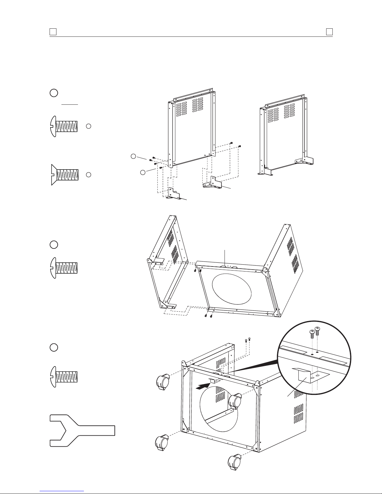
Phillips-head screw 1/4" x 1/2"
Qty: 8
Attach side panels to bottom shelf.
2
Door magnets
to front
LF / RR
Phillips-head screw 1/4" x 1/2"
Qty: 8
Countersunk flat-head screw 3/16" x 3/8"
Qty: 8
Attach castor seats to side panels.
NOTE: Castor seats are labelled for
correct location
1
A
A
B
B
LF
LR
Screw castor wheels into castor seat.
Attach door guide.
3
Phillips-head screw 3/16" x 3/8"
Qty: 2
Castor wheel spanner Qty: 1
Door guide
Page 7
ASSEMBLY
7
7
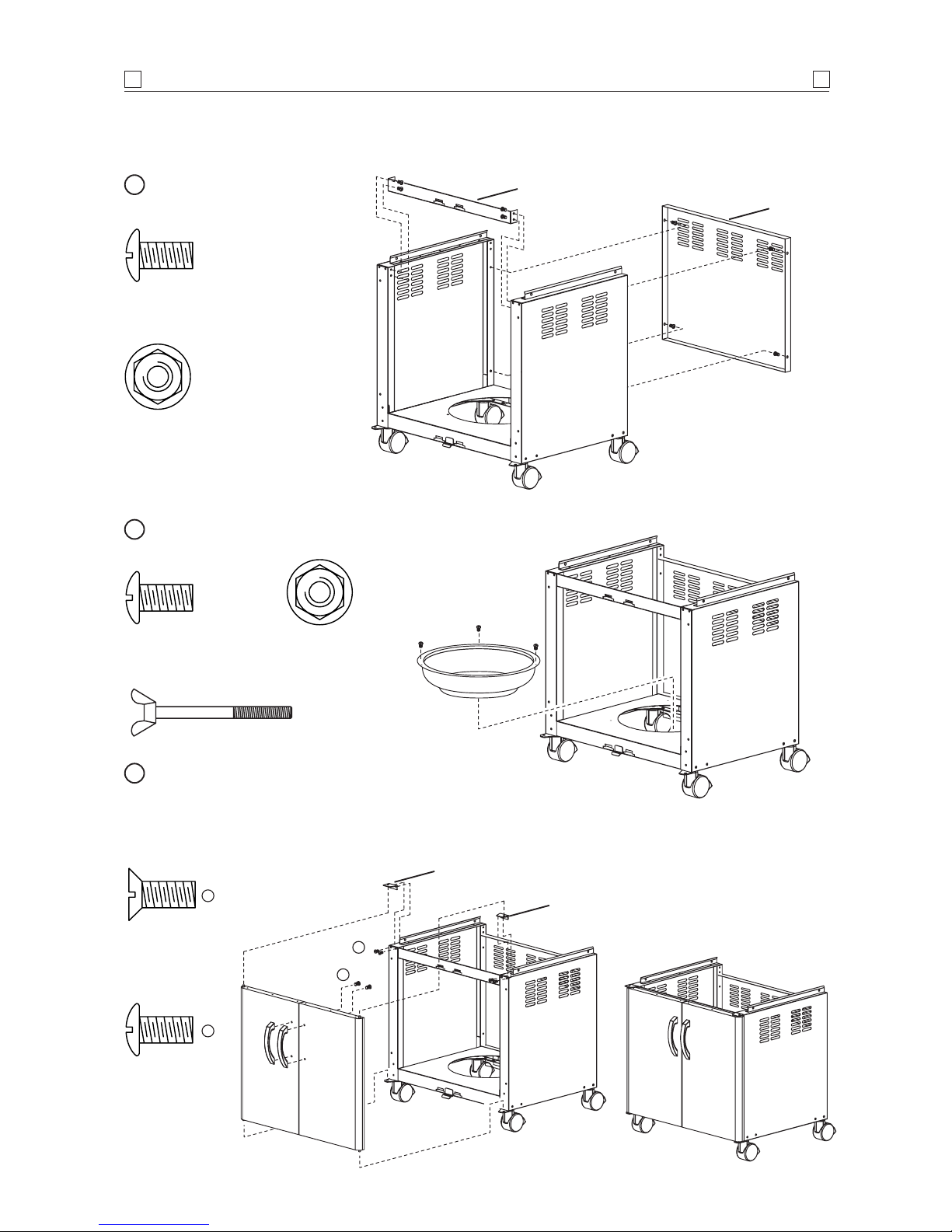
Phillips-head screw 3/16" x 3/8"
Qty: 8
Flange nut 3/16"
Qty: 8
Rear panel
Trolley bracket front
Phillips-head screw
3
/16" x 3/8" Qty: 3
Flange nut 3/16"
Qty: 3
Phillips-head
screw
3
/16" x 1/4"
Qty: 4
Gas cylinder
housing
Door hinge bracket –
top left
Door hinge bracket –
top right
Countersunk flat-head
screw 3/16" x 3/8"
Qty: 4
B
A
A
B
Attach body support brackets and gas cylinder
housing, facing wing bolt to rear.
5
Attach the trolley bracket
front and rear panel.
4
Attach top right and left door hinges. Insert the
bottom door hinge pin into the lower door hinge
bracket holes. Depress the spring loaded top door
hinge pin and line up with the top hinge bracket
holes, and release the pin.
6
Wing bolt
Qty: 1
Page 8
ASSEMBLY
8
8
Phillips-head screw 1/4" x 13/16"
Qty: 4
Washer 1/4"
Qty: 4
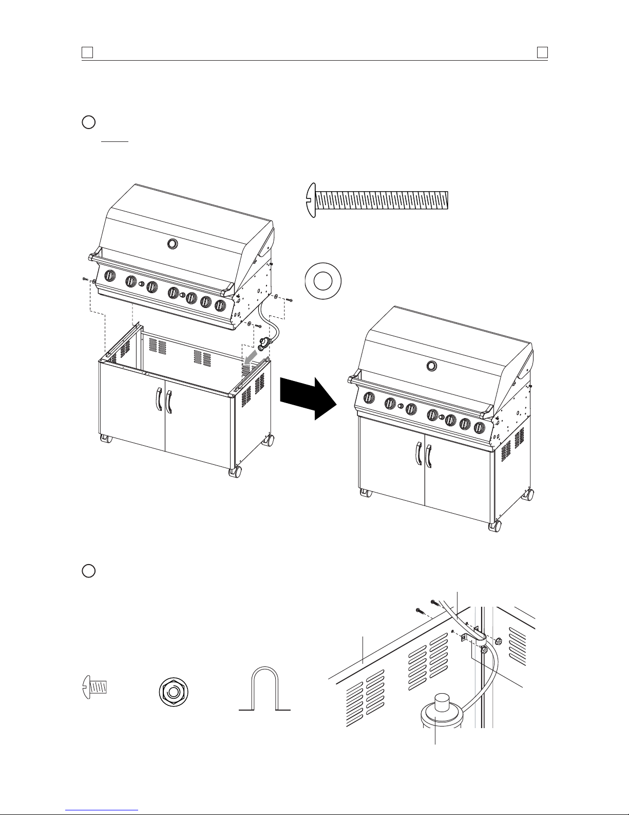
Attach barbecue body to trolley.
NOTE: Cut cable tie from underneath the barbecue
head to release the gas regulator before assembling
onto trolley.
7
Phillips-head
screw
3
/16" x 3/8"
Qty: 2
Flange nut
3
/16"
Qty: 2
Hose holder
Qty: 1
Regulator assembly
Place the LPG regulator inside the trolley through
the opening above trolley rear panel. Press the
hose of the LPG regulator into the hose holder
above trolley rear panel. secure firmly using two
(2)
3
/16"x 3/8" Phillips-head screws and two (2)
3
/16" x flange nuts.
8
Hose
LPG regulator
Trolley rear
panel
Hose
holder
Page 9

Install side shelf brackets.
From the rear of the barbecue, and below the gas
hoses, slide the grease tray side tabs over the side
rails underneath the barbecue body.
Install the grease receptacle under the grease
tray from the front of the barbecue.
9
ASSEMBLY
9
9
Grease
tray
Side shelf
bracket – B
(RF / LR)
Side shelf
bracket – B
(RF / LR)
Side shelf
bracket – A
(LF / RR)
Side shelf
bracket – A
(LF / RR)
Phillips-head
screw
1
/4" x 1/2"
Qty: 8
Grease
receptacle
• DO NOT LINE THE GREASE DRAINING
TRAY WITH FOIL OR ABSORBENT
MATERIALS
• THE GREASE RECEPTACLE MAY BE
LINED WITH FOIL FOR EASY CLEANING
• GREASE / FAT FIRES ARE NOT
COVERED BY WARRANTY.
Page 10

ASSEMBLY
10
10
Install connection hose
Install connection tube to gas fitting and secure
firmly the brass nut of connection tube.
11
Connection hose
Gas fitting
Install left side shelf and side burner frame
Place the side shelf over the left side shelf brackets
and side burner frame over the right side shelf
brackets using four (4)
1
/4"x 1/2" Phillips-head
screws and four (4)
1
/4" flange nuts.
Tighten the left side shelf and side
shelf brackets using four (4)
1
/4"x
1
/2" Phillips-head screws and four (4)
1
/4" flange nuts. Repeat for side
burner frame.
10
Flange nut 1/4"
Qty: 8
Phillips-head screw
1
/4" x 1/2"
Qty: 8
Page 11

ASSEMBLY
11
11
TEST FOR LEAKS WITH A
SOAP SOLUTION, NEVER WITH AN
OPEN FLAME (Refer pages 3 and 4) .
CONNECTING TO, AND DISCONNECTING
FROM GAS SOURCE
2. Attach cylinder connection
device of regulator and hose
assembly to cylinder
valve outlet.
Tighten firmly.
3. Open the gas
cylinder valve
fully to allow gas to flow.
4. Leak test all accessible
connections thoroughly
using a soapy water
solution prior to lighting
the barbecue.
Refer to Safety information, pages 3.
5. If a leak is found, turn gas cylinder valve off and do
not use barbecue until repairs or replacement can
be made.
DISCONNECTING FROM GAS SOURCE
1. Turn the burner control ‘OFF’.
2. Turn the gas cylinder valve off fully.
3.
Detach the regulator assembly from gas cylinder
valve.
CONNECTING TO GAS SOURCE
1. Place the gas cylinder into
the gas cylinder
housing
‘A’ and face
the gas cylinder
valve to the
right rear corner.
Secure with the
wing bolt.
CAUTION: When the appliance is not in use, the
gas must be turned off at the gas cylinder.
This barbecue is also certified for use on natural gas.
Contact your place of purchase for advice in relation to
using your barbecue on natural gas.
Refer to back cover
for contact details.
Barbecues for use on natural gas must be installed
by an authorised person.
NATURAL GAS INSTALLATION
IMPORTANT: Before connecting and disconnecting
barbecue to gas source, ensure burner controls are in
‘OFF’ position.
NOTE:
The ‘OFF’ position on the control panel is
identified by either a small black dot / a short vertical
black line / or the word ‘OFF’.
When the marking, or the word ‘OFF’ printed on
the control knob, aligns with the printed marking on the
control panel, then the burner is in the fully off position.
CAUTION:
When the appliance is not in use, the gas
must be turned off at the gas cylinder
.
Familiarise yourself with the general information and
safety guidelines located at the front of this booklet.
Check to see that gas cylinder is filled and that end of
each burner tube is properly located over each valve
orifice. Set burner controls to
‘OFF’ position.
ENSURING BURNER CONTROLS ARE OFF
• DISCONNECT AND REMOVE GAS
CYLINDER WHEN MANOEUVRING THE
BARBECUE OVER UNEVEN SURFACES
OR CARRYING UP AND DOWN STAIRS
• IF THIS INFORMATION IS NOT
FOLLOWED EXACTLY, A FIRE
CAUSING DEATH OR SERIOUS INJURY
MAY OCCUR!
• DO NOT STORE A SPARE GAS
CYLINDER UNDER OR NEAR THIS
APPLIANCE
• THIS BARBECUE IS ONLY TO BE
USED OUTDOORS.
Direction for
tightening
A
Page 12

INSPECTION
12
12
Product shipping can reposition the rotisserie burner
spark electrode. If your barbecue and side burner are
completely assembled and this rotisserie burner
electrode does not continuously
spark, then conduct
this adjustment.
1. Turn the gas supply off at the gas cylinder.
2. Be sure the AA battery is installed and ensure the
connections are secure.
3. Push the ignition button and watch for a small blue
spark at the rotisserie burner electrode tip. If there is
no spark you must adjust the gap between the
electrode tip and the stainless steel rotisserie burner
screen. The gap should be adjusted to approximately
5 mm or closer.
4. Adjust the gap using needle nose pliers. DO NOT
adjust the gap by hand or touch the white ceramic
electrode insulator. Using one set of needle nose
pliers, securely hold the electrode as shown above.
With another set of pliers, gently bend the tip
end of electrode to within 5 mm of the stainless
steel screen. Be careful not to puncture the screen or
break electrode tip.
5. Try spark electrode test again. Re-adjust if necessary.
BACK BURNER SPARK ELECTRODE TEST
AND ADJUSTMENT – 5012 model
Do not touch the
white ceramic
electrode insulator
1. With burner controls in ‘OFF’ position, open the gas
cylinder valve or connect to gas supply.
2. Upon first assembly the gas lines and burners will
be full of air. In order for the burners to light
properly the lines must fill with gas. It may require
several attempts at lighting the burners before you
are successful.
3. Push the igniter button and check for sparking at
the stainless steel gas collector, located adjacent to
each burner.
4. If a spark is not evident at the gas collector, check
that the ignition lead is firmly attached to the spark
plug.
5. With sparking established at collector box, turn the
burner control to
‘HI’ to establish a flame on the
burner.
6. Push and turn the required burner control as
required in an anti-clockwise direction to the
‘HI’
position. Cross lighting channels inside the barbecue
body enables the flame to transfer across to the
centre and opposite side burners to ignite them.
7. If any burners fail to light after several attempts,
turn off gas supply at source.
Wait until burners cool and inspect for obstructions to
gas flow.
See also Safety instructions (pages 3, 4), Lighting
and Operating instructions (pages 14, 15)
.
BURNER OPERATION
AND IGNITION SYSTEM CHECK
Piezo igniter
5mm
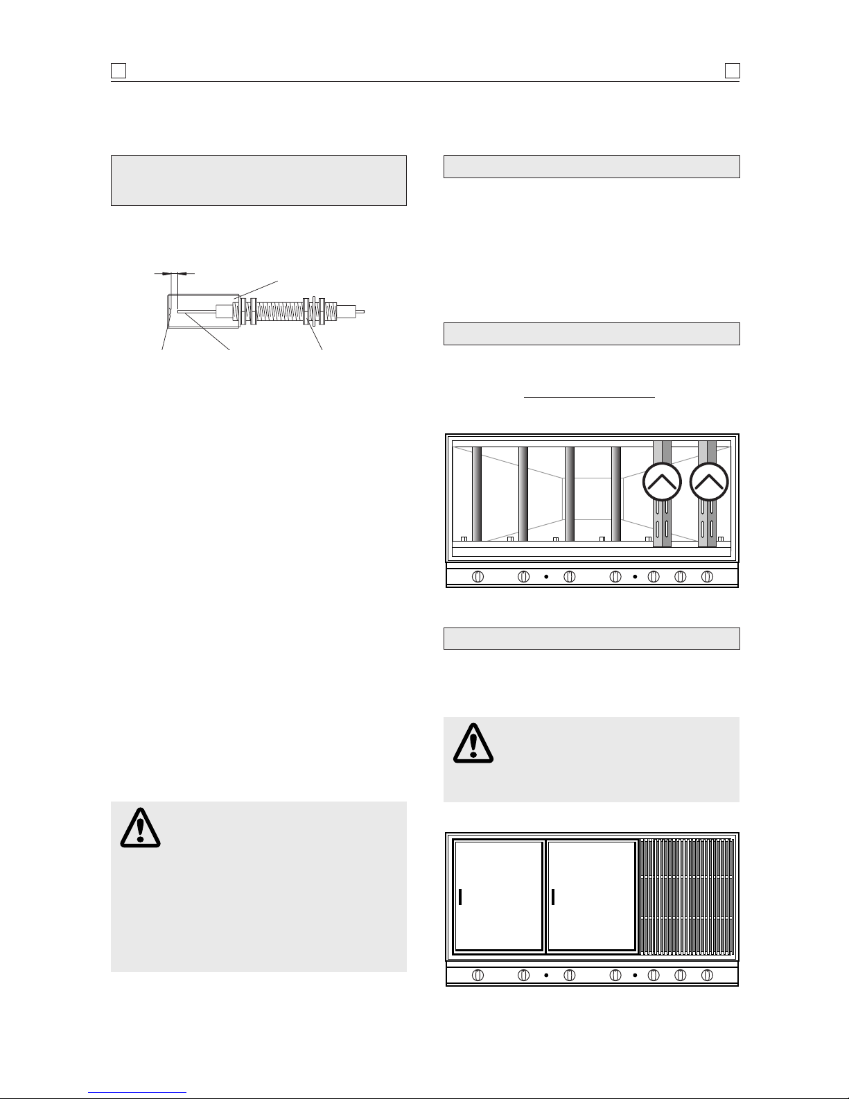
Gas valve assembly Orifice Burner tube
Gas collector /
electrode
AA
battery
Spring
Igniter
cap
Contact
IGNITION BATTERY
Page 13
ASSEMBLY– GENERAL
13
13
The flame tamer plate is designed to reduce flaring. The
plates fit onto the ledge at the front and rear of the barbecue
body. Position with the slots to the front
as shown below.
FLAME TAMERS
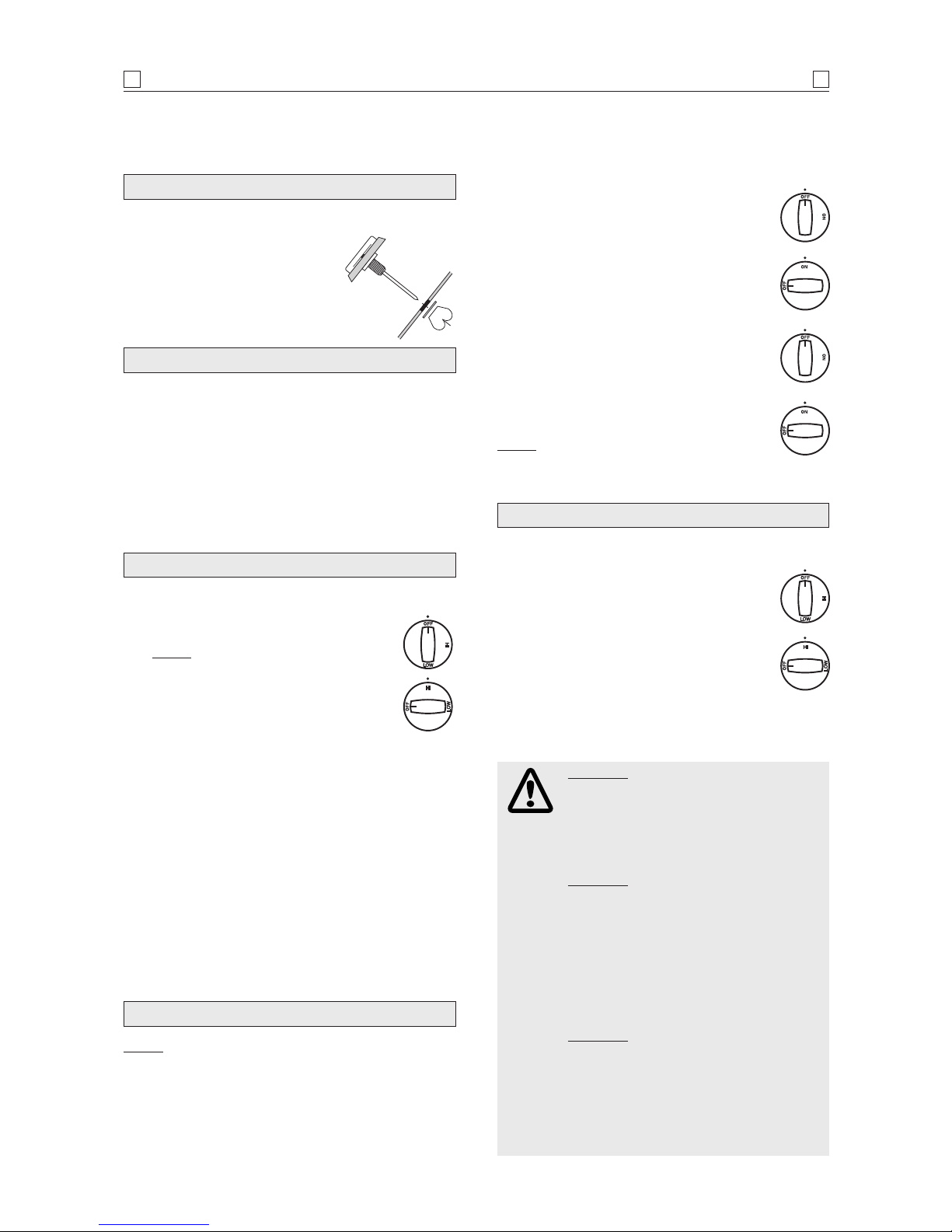
This test will ensure that the spark electrode tips are properly
positioned so your barbecue lights easily and properly.
WITH THE ASSISTANCE OF ANOTHER
PERSON, PERFORM THIS ELECTRODE CHECK
BEFORE PROCEEDING.
Ensure the gas source is turned off – or is disconnected and
all burner control knobs are set to
‘OFF’– and open the lids
/ side shelves.
Have your assistant stand behind to the right of the
barbecue and look toward the front of the barbecue. Never
put your face inside the barbecue.
Press the igniter cap. You should hear a ‘clicking’
sound. Your assistant should see a blue spark within each
gas collector box. If a spark is present the electrode tips
are properly positioned.
If no spark is seen, the spark gap needs to be adjusted as
follows:
• Using an adjustable spanner, loosen the inside nut
until the gas collector box can be turned upward. If
the gap between the spark electrode tip and receiver is
more than 4 - 5 mm use long nose pliers to gently
squeeze the gas collector box to narrow gap. Return
the gas collector box to its original position, secure the
inside nut and try the electrode check again.
If no ‘clicking’ sound is heard:
• AA battery may be installed backwards.
• Electronic wires may be loose. Remove the AA battery
and inspect the igniter junction box found behind the
control panel and reconnect any loose wires.
• CHECK PERFORMANCE OF
BURNERS PRIOR TO INSTALLING
BARBECUE PLATE COMPONENTRY.
Refer pages 14 and 15 for lighting
instructions
• DO NOT SMOKE WHEN ATTEMPTING
TO IGNITE BARBECUE
• NEVER USE VOLCANIC ROCK,
HEAT BEADS OR OTHER MATERIAL
• ALWAYS USE PROTECTIVE GLOVES
WHEN HANDLING HOT COMPONENTS.
• Open side burner lid. Remove plastic shipping band
from burner and pot support.
• Push and turn side burner control knob to
‘HI’. Look
for spark between tip of electrode and burner.
• If you don’t see a spark from side burner electrode,
adjust gap between electrode and burner surface to
4 - 5 mm.
SIDE BURNER ELECTRODE CHECK
+
-
4-5 mm spark
gap
Gas collector
box
Spark
electrode tip
Spark
receiver
Inside
nut
The grill plates must be positioned over the flame tamers.
Position hot plate and grill
plates as indicated below.
COOKING PLATES
DO NOT COVER ENTIRE COOKING
SURFACE WITH SOLID PLATES,
AS THIS WILL RESULT IN POOR
COOKING PERFORMANCE, OR THE
BURNERS MAY GO OUT, CREATING A
HAZARDOUS SITUATION.
Page 14
2. Set burner control knobs to ‘OFF’ and open
the gas cylinder valve.
3. Push and turn back burner control knob to
‘
HI’.
4. Then immediately press the continuous
spark igniter for 3 - 4 seconds to light the
burner.
5. If the burner does not light, turn the control
knob to ‘
OFF’, wait 5 minutes, then retry.
6. Once the burner is ignited, the back burner
will reach cooking temperature quickly.
The orange / red glow will even out in about
5 minutes.
7. For best results, always rotisserie cook with
the hood down.
NOTE: If extra heat is required, then any of the
main burners may be used on the ‘LOW’ setting
only. Do not exceed 250º with hood closed.
NOTE: The location of the back burner makes it more
susceptible to wind conditions that will decrease the
performance of your rotisserie cooking. For this reason
you should not operate the back burner during windy
weather conditions.
1. Open barbecue hood before attempting to light back
burner.
BACK BURNER IGNITION
1. Open barbecue hood before attempting to light burners.
2. Set burner control knobs to
‘OFF’ and open
the gas cylinder valve.
NOTE:
Upon first assembly the gas lines
and burners will be full of air. In order
for the burners to light properly the lines
must fill with gas. It may require several
attempts at lighting the burners before
you are successful.
3. Push and turn the required burner control knob to
‘HI’.
4. Immediately press the continuous spark igniter for
up to 15 seconds to light the burner.
5. If the burner does not light, turn the burner control
knob to
‘OFF’, wait 5 minutes for gas to clear, then
retry.
6. Once the burner is ignited, the adjacent burner can be
lit by simply turning its control knob to ‘
HI’.
7. Adjust burner control knobs to your desired cooking
temperature.
8. If ignition cannot be achieved, perform ignition check
procedure.
Refer to pages 12 and 13.
MAIN BURNER IGNITION
1. Open side burner lid before attempting to light
side burner.
2. Set burner control knobs to
‘OFF’ and
open the gas cylinder valve.
3. Push and turn the control knob anticlockwise until a “click” is heard
.
4. Immediately the piezo igniter will be
triggered to light the burner.
5. If the burner does not light, turn the
control knob to
‘OFF’, wait 5 minutes, then retry.
6. Adjust burner control knob to desired flame level.
SIDE BURNER IGNITION – All models
OPERATION
14
14
Before first use and at the beginning of each barbecue season:
1. Please read
Safety, Lighting and Operating instructions
carefully.
2. Check gas valve orifices, burner tubes and burner
ports for any obstructions.
eg. spiders, webs, insects.
3. Check and ensure the gas cylinder is full.
4. Ensure all connections are securely tightened. Check
for gas leaks.
See pages 3.
NOW YOUR BARBECUE IS READY TO USE
The temperature gauge is used as a guide to cooking
temperatures when cooking with
the hood closed. When an opening
is provided in the hood, this
allows for the installation of the
temperature gauge.
Install as shown
in the diagram, if not factory fitted.
TEMPERATURE GAUGE
CAUTION: IF BURNERS GO OUT DURING
OPERATION, CLOSE GAS SUPPLY AT
SOURCE, AND TURN ALL BURNER
CONTROLS OFF.
OPEN HOOD AND WAIT 5 MINUTES
BEFORE RE-ATTEMPTING TO LIGHT
(ENSURE ACCUMULATED GAS FUMES
HAVE CLEARED).
CAUTION:
SHOULD A GREASE FIRE
OCCUR, ATTEMPT TO CLOSE GAS SUPPLY
AT SOURCE, TURN OFF ALL BURNERS AND
REMOVE FOOD IF POSSIBLE.
KEEP THE VENTILATION OPENINGS OF
THE CYLINDER ENCLOSURE FREE AND
CLEAR FROM DEBRIS.
THE HOOD MUST BE IN THE OPEN
POSITION FOR LIGHTING.
DO NOT SMOKE AT ALL TIMES WHEN
ATTEMPTING TO IGNITE BARBECUE.
CAUTION:
DO NOT MOVE TROLLEY WHILE
BARBECUE IS IN OPERATION.
THE SIDE BURNER IS DESIGNED FOR USE
WITH A WOK UP TO 360 mm DIAMETER,
AND COOKING PAN OF UP TO 200 mm
DIAMETER.
USE OF VERY LARGE POTS MAY RESULT IN
DISCOLOURATION OF THE SURFACE
FINISH, OR CAUSE POOR COMBUSTION.
Page 15

OPERATION
15
15
‘HI’ setting – Use this setting only for warm up, for
searing steaks and chops, and for burning food residue
from the grill plates after the cooking is over. Rarely, if
ever, do you use the ‘
HI’ setting for extended cooking.
‘MEDIUM’ setting (mid-way between ‘HI’ and ‘LOW’).
Use this setting for most grilling, and for cooking
hamburgers and vegetables.
‘LOW’ setting – Use this setting when cooking very lean
cuts such as fish.
Actual cooking surface temperatures vary with
outside temperature and the wind conditions.
COOKING TEMPERATURES
BURN-OFF
Before cooking on your barbecue for the first time,
burn-off any residual oils or foreign matter from the
cooking plates.
ENSURE THE LID IS REMOVED OR
THE HOOD OPEN,
and operate at ‘HI’ setting for
approximately 15 minutes. Allow to cool then wash
grill/plate/pan thoroughly with soap suds and
scrubbing brush. Rinse thoroughly and wipe clean
with a cloth. Your grill/plate/pan is ready to use.
PREHEATING
It is necessary to preheat the barbecue before cooking.
Operate the burner(s) under the cooking surface to
be used at
‘HI’ for approximately 10 minutes before
cooking. Hooded barbecues should be pre-heated with
the hood down.
OPERATING PROCEDURE
If for some reason, igniters fail to produce a spark at the
electrode, barbecue can be lit carefully with a match.
Insert lit match or long-necked butane lighter
through lighting hole located on right side of barbecue
body, after turning the right burner control to the
‘HI’
position.
Sequentially light the remaining burners from right
to left.
MANUAL LIGHTING
Lighting hole
Lit match
• THE SIDE BURNER IS DESIGNED FOR
USE WITH A WOK UP TO 360 mm
DIAMETER AND COOKING POTS UP
TO 200 mm DIAMETER
• USE OF VERY LARGE POTS MAY
RESULT IN DISCOLOURATION OF THE
SURFACE FINISH, OR CAUSE POOR
COMBUSTION.
The fats and juices that drip from the meat may cause
flare-ups. Since flare-ups impart the distinctive taste
and colour for food cooked over an open flame, they
should be expected and encouraged within reason.
Nevertheless, uncontrolled flaring can result in a
ruined meal.
FLARE-UPS
Cooking with the hood in the closed position helps to cook
food more quickly than in conventional barbecues with a
simple lid. The hood
(when closed) helps to retain the heat
more evenly and conserves energy.
IMPORTANT: Never use any burner or combination of
burners on ‘HI’ for extended periods when cooking with the
hood down.
High direct heat when the hood is down may result in
burnt food, or damage to painted surfaces.
When roasting in your barbecue, food should be
positioned over the centre burners either on a roasting
rack with the cooking pan underneath, or directly in the
cooking pan, or placed in a disposable aluminium foil
dish on top of a flame tamer. Remove other grill plate
and hot plate not being used, and ignite burners 1, 2,
5 & 6.
It is recommended not to exceed 250˚C when cooking
with the hood down. The heat from the selected burners
circulates gently throughout the barbecue, cooking the
meat or poultry without any direct flame touching it.
This method greatly reduces flare-ups when cooking
extra fatty cuts, because there is no direct flame to ignite
the fats and juices that drip during cooking.
PRE HEATING
With the hood open, ignite the outer left and right burners.
Once ignition is established, close the hood. Leave the
burners on ‘
HI’ for 10 minutes or until the temperature
reaches a suitable level for cooking. Modulate the
required temperature by turning the left and right burners
progressively to ‘
LOW’.
COOKING WITH THE HOOD DOWN
EXTENDED PERIODS OF PRE-HEATING
WITH THE HOOD DOWN MAY DAMAGE
THIS APPLIANCE.
Page 16

ROTISSERIE COOKING
• Rotisserie cooking produces foods that are moist,
flavoursome and appealing. The rotating food self
bastes. Although the rotisserie is best for larger
pieces of meat or poultry, most cuts can be used if
prepared properly.
• The balancing of the food requires the most attention
in rotisserie cooking. The rotisserie must turn
evenly otherwise the stopping and starting action
will cause the food to cook unevenly and possibly
burn the heavier side.
Refer to the diagram below.
• The easiest foods to balance are those of uniform
shape and texture. To test if the food is balanced
correctly when secured, place the ends of the
rotisserie skewer loosely in the palm of your
hands. Give the spit a quarter turn and if there is
no tendency to roll and it is stable give it a another
quarter turn. It should rest without turning in each
of these positions.
It can then be attached to the barbecue.
• When using poultry, truss the bird tightly so that
wings and drumsticks are close to the body of the
bird. The cavity of the bird can be stuffed prior to
this, if you wish. Pull the neck skin down and
using a small skewer fix to the back of the bird.
Push the rotisserie skewer through lengthwise,
catching the bird in the fork of the wishbone.
Centre the meat and tighten the holding forks. Test
the balance as described above.
• A rolled piece of meat only requires the rotisserie
skewer to be inserted through the centre of the
length of meat, then secured and balanced using
the forks.
• For meats which are un-boned, it is best to secure
the rotisserie skewer diagonally through the
meaty sections. If protruding bones or wings
brown too quickly, cover with pieces of foil.
SETTING UP THE BARBECUE
• Remove all the cooking plates from the barbecue
and position the flame tamer centrally. Place either
an oven proof cooking pan or disposable aluminium
foil dish on top of the flame tamer under the food
being cooked so that it catch any drips from the
food above. The drippings can be used to make
gravies and other sauces to accompany the cooked
meat.
• Once the barbecue has been set up, pre-heat the
barbecue according to the manufacturer instructions.
Close the hood when you start to cook.
• For foods with little fat you may wish to cook them
directly over lit burners to give a charred effect.
This should only be done towards the end of the
cooking for no longer than the time required to
give the desire visual effect. Do not attempt this
with fatty foods as this will cause flare-ups and
excessive smoke.
COOKING TIMES
• This will vary according to the type and weight
of food you are cooking. However as a guide the
cooking times on a rotisserie are similar to
conventional oven cooking.
OPERATION
16
16
SAFETY POINTS
• Do not operate damaged rotisserie.
• Do not use rotisserie in poor weather conditions.
• Avoid contact with hot surfaces.
• Always load rotisserie to barbecue before switching
motor on.
• Always turn rotisserie
‘OFF’ before removing from
barbecue.
• Do not leave rotisserie on barbecue when not in
use.
LOADING THE SPIT RODS
• Assemble rotisserie rod as shown.
• Centre food on the spit rod.
• Use butcher string to secure loose portions.
Rotisserie is available as an optional extra from your place of
purchase.
ROTISSERIE
Page 17

• SHOULD A FLASHBACK FIRE OCCUR
IN OR AROUND THE BURNER TUBES,
FOLLOW THE INSTRUCTIONS BELOW.
FAILURE TO COMPLY WITH THESE
INSTRUCTIONS COULD RESULT IN A
FIRE OR EXPLOSION THAT COULD
CAUSE SERIOUS BODILY INJURY,
DEATH, OR PROPERTY DAMAGE
• SHUT OFF GAS SUPPLY TO THE GAS
BARBECUE
• TURN THE CONTROL KNOBS TO OFF
POSITION
• OPEN THE BARBECUE LID.
PUT OUT ANY FLAME WITH A FIRE
EXTINGUISHER
• ONCE THE BARBECUE HAS COOLED
DOWN, CLEAN THE BURNER TUBES
AND BURNERS ACCORDING TO THE
CLEANING INSTRUCTIONS IN THIS
OPERATOR'S MANUAL.
1. Turn gas off at source and turn burner control
knobs to
‘OFF’. Wait at least five (5) minutes for
gas to clear, then retry.
2. If your barbecue still fails to light, check gas supply
and connections.
3. Repeat lighting procedure. If your barbecue still
fails to operate, turn the gas off at source, turn the
control knobs to
‘OFF’, then check the following:
•
Misalignment of burner tubes over orifices
Correction: Reposition burner tubes over orifices.
•
Obstruction in gas line
Correction: Remove fuel line from barbecue. Do not
smoke! Open gas supply for one second to clear
any obstruction from fuel line. Close off gas supply
at source and reconnect fuel line to barbecue.
•
Plugged orifice
Correction: Remove burners from barbecue by
pulling cotter pin (beneath burner) using long nose
pliers. Carefully lift each burner up and away from
gas valve orifice. Remove the orifice from gas valve
and gently clear any obstruction with a fine wire.
Then reinstall all orifices, burners, cotter pins and
cooking components.
If an obstruction is suspected in gas valves or
manifold, contact your place of purchase or
manufacture.
•
Obstruction in burner tubes
Correction: Follow the burner tube cleaning
procedure on page 20 of this operator's manual.
•
Misalignment of igniter on burner
Correction: Check for proper position of the
electrode tip as shown on pages 12 and 13. The gap
between the spark electrode tip and spark receiver
should be approximately 4 - 5 mm. Adjust if
necessary. With the gas supply closed and all
control knobs set to
‘OFF’ press the electronic
igniter cap and check for the presence of a spark at
the electrode.
•
Disconnected electronic wires
Correction: Inspect the igniter junction box found
behind the control panel. Connect loose electronic
wires to junction box and try to light the barbecue.
•
Weak AA battery
Correction: Unscrew the igniter cap and replace the
battery.
IF THE BARBECUE FAILS TO LIGHT
CAUTION: If burners go out during operation, close gas
supply at source, and turn all gas valves off. Open hood
and wait 5 minutes before re-attempting to light (this
allows accumulated gas fumes to clear).
CAUTION:
Should grease fire occur, close gas supply at
source, turn off all burners and remove food until fire is
out.
KEEP THE VENTILATION OPENINGS OF THE
CYLINDER ENCLOSURE FREE AND CLEAR FROM
DEBRIS.
FAULT FINDING
17
17
Page 18

Before initial use, and periodically, wash your cooking
plates in a mild soap and warm water solution. You can
use a wash cloth or vegetable brush to clean your cooking
plates.
It is recommended the cooking plates be coated with
a thin layer of cooking oil on a regular basis to prevent
rusting. Slight rusting can be removed with a scrubbing
brush before use.
CLEANING THE COOKING PLATES
Proper care and maintenance will keep your barbecue
in top operating condition and prolong its life. Follow
these cleaning procedures on a timely basis and your
barbecue will stay clean and operate with minimum
effort.
CAUTION: Be sure your barbecue is off and cool before
cleaning.
CLEANING AND MAINTENANCE
Before initial use, and periodically thereafter, we suggest
you wash your barbecue using a mild soap and warm
water solution. You can use a wash cloth or sponge for
this process. Do not use a stiff wire or brass brush. These
will scratch stainless steel and chip painted surfaces
(varies by model) during the cleaning process.
CLEANING EXTERIOR SURFACES
To reduce the chance of fire, the grease draining tray
and grease receptacle should be visually inspected
before each barbecue use. Remove any grease and wash
grease tray and receptacle with a mild soap and warm
water solution.
NOTE: Grease / fat fires are not covered by warranty.
CLEANING THE GREASE TRAY
AND RECEPTACLE
MAINTENANCE
18
18
Periodically you should wash the flame tamer in a
soap and warm water solution. Use a vegetable brush
to remove stubborn burnt-on cooking residue. Dry
the flame tamers thoroughly before you re-install
them into the barbecue.
CLEANING THE FLAME TAMERS
FAILURE TO READ AND FOLLOW THE
USE AND CARE INSTRUCTIONS COULD
RESULT IN A FIRE OR EXPLOSION
THAT COULD CAUSE SERIOUS BODILY
INJURY, DEATH OR PROPERTY
DAMAGE.
The stainless steel over time will be affected by ‘tea
staining’
(the brown discolouration of some stainless steel).
Tea staining can be reduced by washing the surface
with mild detergent and warm water. This should then
be followed by rinsing with clean cold water. We
recommend the surface then be wiped dry with a clean
cloth.
CARE FOR STAINLESS STEEL SURFACE
IN COASTAL AREAS, FREQUENT
CLEANING AND THE USE OF A COVER
IS RECOMMENDED TO PROLONG THE
LIFE OF THE APPLIANCE.
SALTY AIR WILL ADVERSELY AFFECT
EXPOSED PARTS.
DO NOT USE OVEN CLEANER TO CLEAN
THE BARBECUE.
Page 19

• KEEP BARBECUE AREA CLEAR AND
FREE FROM COMBUSTIBLE MATERIALS,
GASOLINE AND OTHER FLAMMABLE
VAPOURS AND LIQUIDS
• DO NOT OBSTRUCT THE FLOW OF AIR
FOR COMBUSTION AND VENTILATION
• KEEP THE VENTILATION OPENINGS OF
THE CYLINDER ENCLOSURE CABINET
FREE AND CLEAR OF DEBRIS
• VISUALLY CHECK BURNER FLAMES
OCCASIONALLY TO ENSURE PROPER
FLAME PATTERN AS SHOWN BELOW
• FAILURE TO COMPLY WITH THESE
INSTRUCTIONS MAY RESULT IN A
HAZARDOUS SITUATION WHICH, IF
NOT AVOIDED, MAY RESULT IN
INJURY.
Magnified view
of burner flame
through lighting
hole
Burning-off excess food after every cookout will keep it
ready for instant use. However,at least every 3 months
you must give the entire barbecue a thorough cleaning
to minimise your risk of grease fire and keep the barbecue
in top shape.
Follow these steps:
1. Turn all burner valves to the full ‘OFF’ position.
2. Turn the LP gas cylinder valve to the full
‘OFF’
position.
3. Disconnect the regulator from the gas cylinder.
Inspect the hose with regulator assembly for
cracking, cuts or any other damage, and replace as
necessary.
Refer to the Parts List in this operator's
manual, pages 22 - 23.
4. Remove and clean the flame tamers, cooking plates
and barbecue burners.
5. Cover each gas valve orifice with aluminum foil.
6. Brush the inside and bottom of the barbecue with a
fibre pad or nylon brush and wash with a mild
soap and warm water solution. Rinse thoroughly
and let dry.
7. Remove aluminum foil from orifices and check
each orifice for obstruction.
8. Check each spark electrode, adjusting as needed.
The space between the spark electrode tip and
spark receiver should be approximately 4 - 5 mm.
9. Replace the burners and adjust the gas collector
box. The edge of the collector box should be overlapping the burner port.
10. Reconnect the gas source and observe the burner
flame for correct operation.
11. Replace flame tamers and cooking plates.
ANNUAL CLEANING OF THE
BARBECUE INTERIOR
MAINTENANCE
19
19
• BEWARE OF SPIDERS.
BURNER TUBES SHOULD BE
INSPECTED AND CLEANED
PERIODICALLY.
• SPIDERS AND SMALL INSECTS CAN
OCCASIONALLY SPIN WEBS OR MAKE
NESTS IN THE BURNER TUBES.
THESE WEBS CAN LEAD TO A GAS
FLOW OBSTRUCTION WHICH COULD
RESULT IN A FIRE IN AND AROUND
THE BURNER TUBES
• THIS TYPE OF FIRE IS KNOWN AS
‘FLASH-BACK’ AND CAN CAUSE
SERIOUS DAMAGE TO YOUR
BARBECUE AND CREATE AN UNSAFE
OPERATING CONDITION FOR THE
USER
• ALTHOUGH AN OBSTRUCTED BURNER
TUBE IS NOT THE ONLY CAUSE OF
‘FLASH-BACK’ IT IS THE MOST
COMMON CAUSE AND FREQUENT
INSPECTION AND CLEANING OF THE
BURNER TUBES IS NECESSARY.
We recommend that you minimise the barbecue’s
exposure to the elements. High moisture content in the
air
(rain, mist, salt spray etc.) can affect metal components
and lead to material breakdown. If left in an area
subjected to high moisture content, we strongly
recommend that you observe the cleaning procedure
on a regular basis and cover the appliance whilst not in
use
(covers are available as an optional extra). Material
breakdown from high moisture conditions can be
avoided if the appliance is well protected from the
weather and regular cleaning is carried out.
STORAGE
Page 20

To reduce the chance of FLASHBACK FIRE you must
clean the burner tubes as follows at least once a month
in summer and fall or whenever spiders are active in
your area, and if your barbecue has not been used for an
extended period of time.
1. Turn all burner valves to the full
‘OFF’ position.
2. Turn the LP gas cylinder valve to the full ‘OFF’
position.
3. Detach the LP gas regulator assembly from your
gas barbecue.
4. Remove the cooking plates, flame tamer plates and
grease trays from your barbecue.
5. Remove the screw from the rear of each burner
using a Phillips-head screwdriver.
6. Carefully lift each burner up and away from the
gas valve orifice.
7. Check and clean burner/venturi tubes for insects
and insect nests. A clogged tube can lead to a fire
beneath the barbecue.
8. Refer to diagram 1 and perform one of these three
cleaning methods:
METHOD 1: Bend a stiff wire or wire coat hanger into a
small hook as shown and run the hook through the
burner tube and inside the burner several times to
remove debris.
METHOD 2: Use a bottle brush with a flexible handle
and run the brush through the burner tube and inside
the burner several times to remove any debris.
METHOD 3: Use an air hose to force air through each
burner tube. The forced air should pass debris or
obstructions through the burner and out the ports.
Regardless of which burner cleaning procedure you use,
we recommend you also complete the following steps to
help prolong burner life.
1. Use a fibre pad or nylon brush to clean the entire
outer surface of each burner until free of food
residue and dirt.
2. Clean any clogged ports with a stiff wire, such as
an open paper clip.
3. Inspect each burner for damage
(cracks or holes) and
if such damage is found, order and install a new
burner. After installation, check to ensure that the
gas valve orifices are correctly placed inside the
ends of the burner tubes. Also check the position of
your spark electrode.
CLEANING THE BURNER TUBES
AND BURNER PORTS
FOR SAFE OPERATION ENSURE THE
GAS VALVE ASSEMBLY ORIFICE IS
INSIDE THE BURNER TUBE BEFORE
USING YOUR BARBECUE. See diagram.
IF THE ORIFICE IS NOT INSIDE THE
BURNER TUBE, LIGHTING THE
BURNER MAY CAUSE EXPLOSION
AND / OR FIRE RESULTING IN SERIOUS
BODILY INJURY AND / OR PROPERTY
DAMAGE.
MAINTENANCE
20
20
Gas valve assembly Orifice Burner tube
BURNER IS TO BE INSTALLED
WITH THE CROSS IGNITION HOLES
UNDERNEATH.
Diagram 1.
To clean burner tube, insert hook as indicated by the
arrow.
Burner tubeCross lighting holes Cross lighting holes
Page 21

THIS PAGE HAS BEEN LEFT INTENTIONALLY BLANK
21
21
Page 22

PARTS DIAGRAM
22
22
This diagram is provided to assist you
identify parts if replacement is necessary.
Contact your place of purchase or the
manufacturer to enquire about parts,
availability and or service.
Items included in your barbecue
specification may differ from the parts
list, depending on region or specific dealer
specification.
1
3
4a
53
6
2b
4b
5
2a
4
7
7a
9
16a
8
16b
10
59a
12
13
11
60
61
59b
15b
14b
27
35
37
36
56
46c
42
14
21
28
64
66
65
15a
26
30
18
34
54
55
25
14a
48
22a
22b
38
24b
24a
23a
23b
24c
19
20
62
17
43a
41a
40a
46a
44
49
45
46d
57b
57a
58
63
41b
46b
47
43b
40b
31
29
32
33
51
52
50, 50a
Page 23

PARTS LIST
23
23
Ref Description Part No.
Qty
1 Hood P00145044C 1
2a Hood hinge P05501018A 2
2b Protective pad P05518002I 2
3 Temperature gauge P00601011B 1
4 Hood handle P00206004M 1
4a Hood handle bracket – left P00301086A 1
4b Hood handle bracket – right P00302086A 1
5 Name plate P00415006C 1
6 Grill plate P01615028H 4
7 Hot plate P01702008K 1
7a Cooking pan P05805011F 1
8 Burner – main P02008015A 6
9 Flame tamer P01708033E 4
10 Bowl wind shield P06905028A 1
11 Rear wind shield P0075101IB 1
12 Burner bracket P0220606ED 1
13 Bowl heat shield P06903034A 1
14a Bowl panel – left P0072078NA 1
14b Bowl panel – right P0072179NA 1
15a Bowl panel – front P00738634A 1
15b Bowl panel – rear P00725674A 1
16a Flame tamer bracket – front P03328050A 6
16b Flame tamer bracket – rear P03328051A 6
17 Gas collector with electrode P02609002B 6
18 Wire set P02615081A 1
19 Heat shield P03010121B 1
20 Gas valve – main without jet P03222132A 6
20a Gas jet – main burner P06517005A 6
21 Manifold P05013012A 1
22a Control panel – top P02914021A 1
22b Control panel – bottom with screen print P0291401BA 1
23a Igniter – 6 point P02502075C 1
23b Igniter – 2 point P02502192C 1
24a Control knob – main burner P03419413L 6
24b Control knob seat – main / back burner P03415014S 7
24c Control knob – back burner P03419403L 1
25 Side shelf – left P01106042S 1
26 Control knob – side burner P03401043S 1
27 Side shelf bracket – RF / LR P01206005B 2
28 Control knob seat – side burner P03408053S 1
29 Side shelf lid P0011538P4 1
30 Side shelf body P011020364 1
31 Side shelf pot support P00805010B 1
32 Side shelf trim plate P01108012S 1
33 Side burner P02002012A 1
34 Side shelf bracket – LF / RR P01204005B 2
35 Grease draining tray P02717115B 1
36 Trolley bracket – front P033050194 1
37 Grease receptacle P02701187B 1
38 Regulator P03603008A 1
39 Connection tube P03705084F 1
40a Trolley panel – left P07605005B 1
40b Trolley panel – right P07606005B 1
41a Door hinge bracket – top left P03313006D 1
41b Door hinge bracket – top right P03313007D 1
42 Door bracket – upper P03301037D 1
43a Bowl support bracket – left P03315001D 1
43b Bowl support bracket – right P03315002D 1
44 Trolley bottom shelf P01004065D 1
45 Wing bolt S233G05261 1
46a Castor seat – LF P05327019G 1
46b Castor seat – RF P05327020G 1
46c Castor seat – LR P05327018G 1
46d Castor seat – RR P05327017G 1
47 Castor – 3” P05112002A 4
48 Grease tray track P05330102G 2
49 Gas cylinder frame P04021003C 1
50 Gas valve – side without jet P03226009C 1
50a Gas jet – side burner P06519081A 1
51 Ignition wire set – side P02607002A 1
52 Side burner bracket P03309003F 1
53 Cooking rack – fixed P01508007H 1
54 Tool holder P05212013F 1
55 Tool hook P05514130L 3
56 Trolley rear panel P07702044B 1
57a Door – left P04305004D 1
57b Door – right P04306004D 1
58 Door handle P00201001C 2
59a Back burner P02007014A 1
59b Gas jet – back burner P06531001A 1
60 Back burner extension tube P03717039B 1
61 Back burner wind shield panel P06905029B 1
62 Gas valve – back burner P03222131A 1
63 Door guide plate P05510024G 1
64 Lighting stick P05507031E 1
65 Side burner hose bracket P03327028Q 2
66 Gas fitting P03904001A 1
Page 24

PART N O. P80140220A Printed 06/2007 All specifications are subject to change without notice.
RINNAI NEW ZEALAND. LTD
Head Office: 691 Mt. Albert Rd, Royal Oak, Auckland.
PO Box 24068.
Tel (09) 625 4285. Fax (09) 624 3018.
Internet: www.rinnai.co.nz
Email: sales@rinnai.co.nz
For your local
Service Centre
contact: 0800 RINNAI (0800 746624).
 Loading...