

Page 1
This appliance shall be installed in accordance with:
• Manufacturer’s Installation Instructions
• Current AS/NZS 3000, AS/NZS 3500 & AS 5601
• Local Regulations and Municipal Building Codes
This appliance must be installed, serviced and removed by an Authorised Person.
All Rinnai gas products
are A.G.A. certified.
Distributed and serviced in Australia under a Quality
System certified as complying with ISO 9001 by
SAI Global
CONSTELLATION
Models: 800 / 1000
Decorative Flame Fire
Operation / Installation Manual
Models available: Black (CONB) & Stainless Steel (CONSS)
Primarily a decorative effect appliance. Not certified as a space heater.
Page 2

Rinnai Australia - ii - Constellation Model 800/1000 - Operation Manual
This appliance must be installed by an Authorised person. The installation of gas and electr icity must
conform to local regulations.
The installation must also comply with the instructions supplied by Rinnai.
Your Constellation Flame Fire has been approved by the Australian Gas Association. The A.G.A.
Approval Number is shown on Data plate.
Please keep this instruction booklet in a safe place for future reference.
All dimensions referred to in these instructions are in millimetres, unless otherwise specified.
As a purchaser of a high quality Rinnai product, we provide you with the following warranty
on your new Decorative Flame Fire.
Free Labour Period Free Parts Period
FANS 1 Year 2 Years
COMBUSTION CHAMBER 1 Year 10 Years Pro-Rata*
ALL OTHER PARTS 1 Year 1 Year
* Combustion chamber full replacement parts costs in the first year, reducing 10% per year thereafter.
The benefits conferred by this guarantee are in addition to all other rights and remedies in
respect of the product which you have under the Trade Practices Act and other State and
Territory Laws.
The appliance must be installed correct ly, and the installation must conform to all local
regulations.
The installation must also comply with the instructions supplied by Rinnai.
The appliance must be installed and serviced by an Authorised Person.
No parts or functions should be modified or permanently removed from this appliance.
Please note: General cleaning, maintenance and wear and tear are not necessarily cove red
by the warranty. Service calls of this nature may be charg e ab le.
For future reference please take a moment to complete the following information:
Your Retailer: ______________________________________________
Name: ______________________________________________
Telephone No. ______________________________________________
Date of Purchase: ________ / ________ / _______________________
REGULATORY INFORMATION
WARRANTY
Page 3

Rinnai Australia - iii - Constellation Model 800/1000 - Operation Manual
REGULATORY INFORMATION ..............................................................................ii
WARRANTY ............................................................................................................ii
ABOUT YOUR NEW CONSTELLATION ................................................................4
GENERAL DESIGN LAYOUT..................................................................................4
FEATURES .............................................................................................................4
REMOTE CONTROL ..............................................................................................5
SAFETY POINTS ....................................................................................................6
OPERATION ...........................................................................................................9
OPERATION USING THE CONTROL PANEL ......................................................9
TURNING THE CONSTELLATION ‘ON’ .................................................................9
TURNING THE CONSTELLATION ‘OFF’ ...............................................................9
ADJUSTING THE FLAME .......................................................................................9
ADJUSTING THE FAN ...........................................................................................9
OPERATION USING THE REMOTE CONTROL ...................................................9
USING THE TIMER ................................................................................................9
CARE AND MAINTENANCE ................................................................................10
CONSTELLATION FLAME FIRE OPERATION CHARACTERISTICS .................10
TROUBLE SHOOTING CHECK LIST ...................................................................1
0
CLEANING ............................................................................................................10
SERVICE ..............................................................................................................10
INSTALLATION MANUAL .....................................................................................11
CONTACT INFORMATION ...................................................................................24
CUSTOMER MANUAL
Page 4
Rinnai Australia - 4 - Constellation Model: 800/1000 - Operation Manual
ABOUT YOUR NEW CONSTELLATION
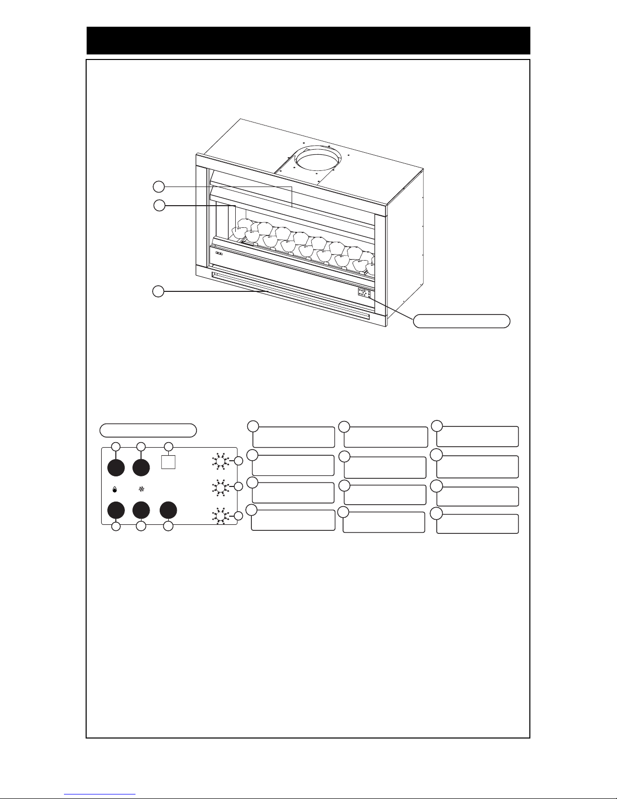
GENERAL DESIGN LAYOUT
FEATURES
• Push Button Operation:
One touch of the ON/OFF button operates the Constellation Flame Fire.
• Remote Control:
Full function cordless remote control incorporates electronic timer, which allows the
Constellation Flame Fire to operate for a set period of 30 minutes.
11
12
10
ON / OFF INDICATOR
2
4
REMOTE CONTROL
RECEIVER
3
6
7
1
5
ON / OFF BUTTON
8
FLAME - UP
ADJUSTMENT
9
FLAME - DOWN
ADJUSTMENT
FAN - UP
ADJUSTMENT
10
FAN - DOWN
ADJUSTMENT
11
FAN - HIGH INDICATOR
12
FAN - LOW INDICATOR
WARM AIR
DISCHARGE LOUVRES
IMITATION
COALS OR PEBBLES
ROOM AIR RETURN
LOUVRE
CONTROL PANEL
CONTROL PANEL
+
+
-
-
17
2
36
4
5
8
9
Page 5
Rinnai Australia - 5 - Constellation Model 800/1000 - Operation Manual
ABOUT YOUR NEW CONSTELLATION
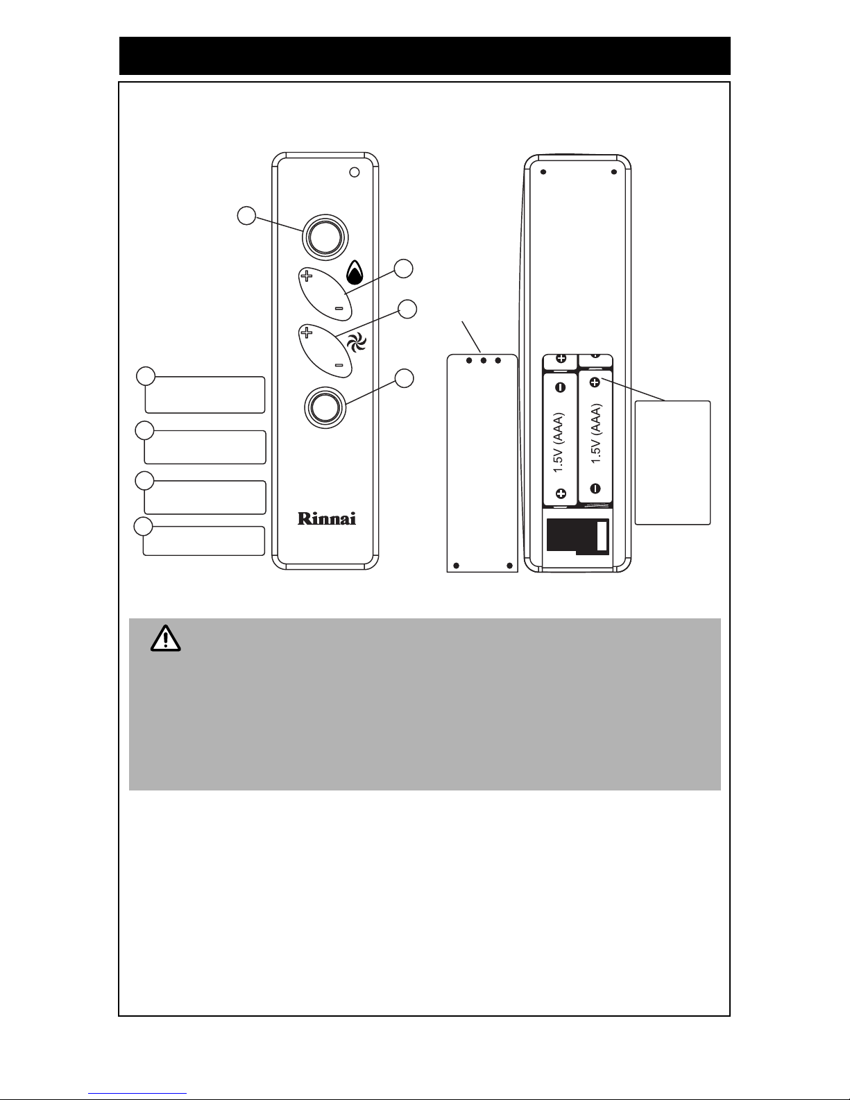
REMOTE CONTROL
The remote control has all the features of the control panel plus the additional Timer Function.
• Uses 4 x 1.5V (AAA) batteries. Do not mix old and new batteries.
• Remove batteries if the remote control is not going to be used for a long
period. This will help avoid damage from leaking batteries.
• Some fluorescent lights may interfere with the transmission of remote control
signals. In this case changing the position from which you are operating the
remote control may help.
• Avoid leaving the remote control in direct sunlight an d do not place it cl ose to
the warm air discharge louvres on the appliance.
• Avoid dropping the remote control or getting it wet.
FLAME BUTTON
2
3
1
FAN BUTTON
1
2
3
ON / OFF BUTTON
4
TIMER BUTTON
4
BATTERIES
The remote contol is
powered by
4 x 1.5V (AAA) type
batteries.
To replace batteries
simply slide open the
cover located on the
back of the remote
control. When installing
new batteries ensure
that the correct
polarity is observed.
BATTERY
COMPARTMENT
COVER
NOTE
Page 6
Rinnai Australia - 6 - Constellation Model 800/1000 - Operation Manual
SAFETY POINTS
UNPACKING THE APPLIANCE:
Check for damage. If your Constellation Flame Fire is damaged, contact your supplier for advice.
Before installing the appliance, check the label for the correct gas type (see gas type label on top of
data plate and on Injector Block bracket). Refer to local gas authority for confirmation of gas type if
you are in doubt.
The following items should also be included in the carton: Operation / Installation manual, remote
control, 4 x AAA batteries, flexitube and reducing flare for gas connection.
IMPORTANT:
IF YOU SMELL GAS:
1. Turn off gas at the meter or LP gas cylinder.
2. Extinguish any open flame.
3. Open windows.
4. Do not touch electrical switches.
5. Do not use the conventional telephone in the building in which the unit is installed.
6. Contact your gas supplier from a neighbours telephone or use a mobile phone away from
the building in which the appliance is installed.
a. The appliance must be installed by an authorised person in accordance with the local
gas and electrical authority regulations.
b. For information on gas consumption, see data plate on the appliance.
c. This appliance must not be installed where curtains or other combustible materials
could come into contact with it. In some cases curtains may need restraining.
d. Ensure that the area in which the appliance is installed has adequate fixed
ventilation. This fixed ventilation must be provided in accordance with AS 5601 ‘Gas
Installations’: Note that the ventilation requirements for a ‘Decorative’ Gas Log Fire
apply.
e. DO NOT connect to an LPG/Propane Gas cylinder indoors. If the appliance requires
conversion to suit LPG/Propane Gas, this must be carried out only by an authorise d
person.
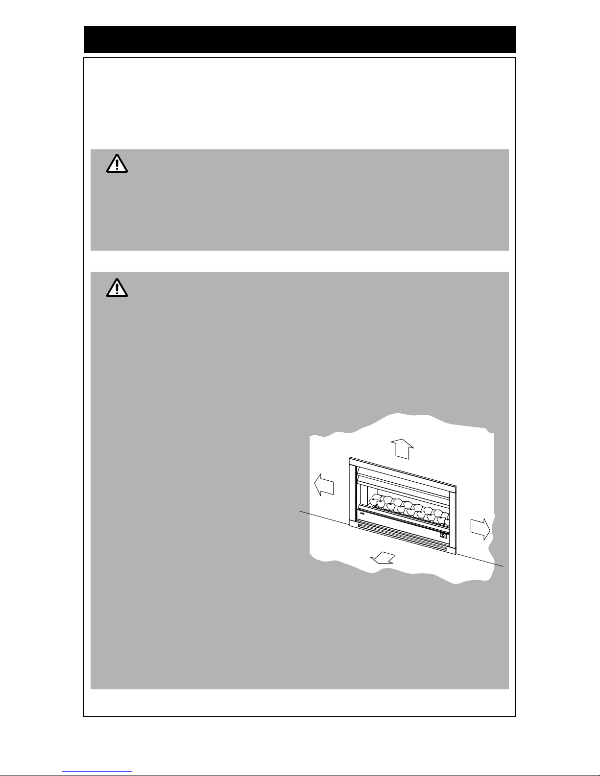
f. Appliance must not be located
below a power socket-outlet.
g. Heat emanating from the front
of this appliance may over
time affect the appearance of
some materials used for
flooring such as carpet, vinyl,
cork or timber. This effect may
be amplified if the air in the
room contains cooking
vapours or cigarette smoke . To
avoid this possibility, it is
recommended that a mat be
placed in front of the
appliance, extending at least
750 mm in front of it.
h. The appliance is not intended
for use by young children or
infirm persons without
supervision.
i. Young children or the infirm should be supervised to ensure they do not play with
this appliance.
j. If the power cord is damaged or requires replacing, it must be replaced by the
manufacturer or the manufacturer's agent or similarly qualified person in order to
avoid a hazard.
k. This appliance must not be modified.
IMPORTANT
IMPORTANT
3
0
0
m
m
1
0
0
0
m
m
3
0
0
m
m
3
0
0
m
m
The above diagram shows the clearances required
around this appliance whilst in operation.
Page 7
Rinnai Australia - 7 - Constellation Model 800/1000 - Operation Manual
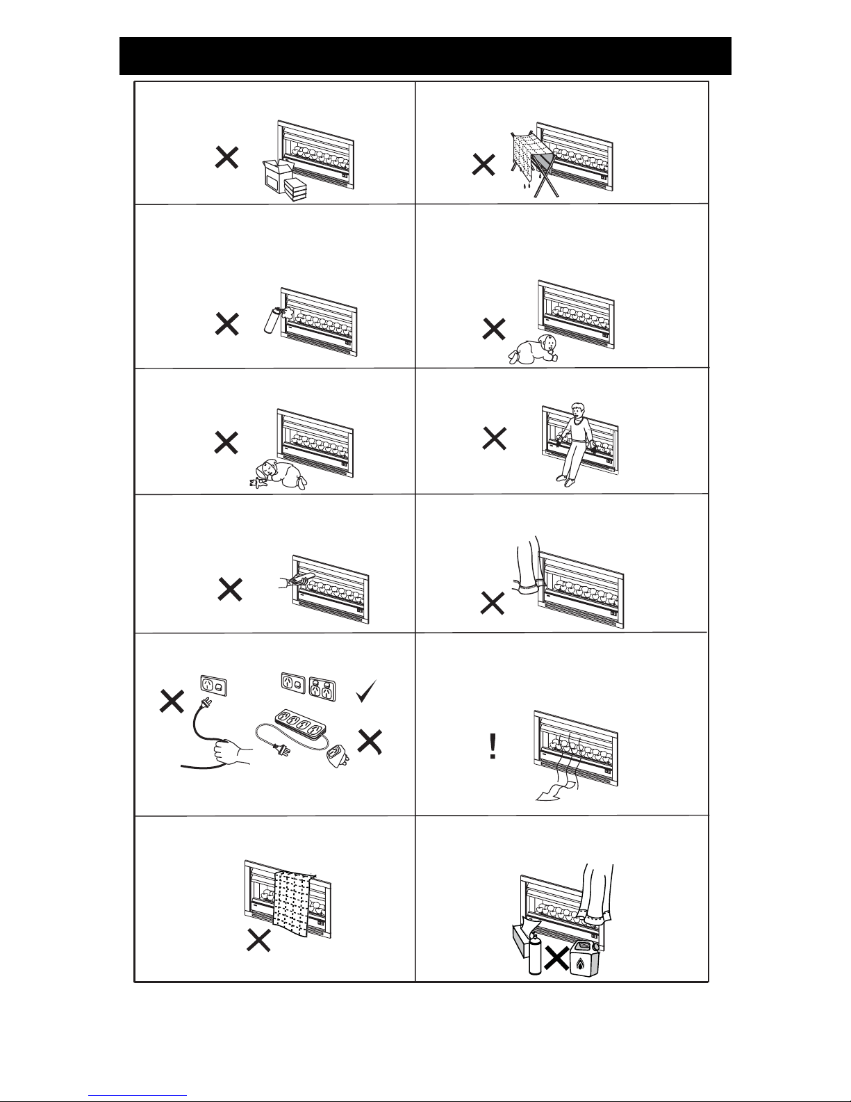
SAFETY POINTS
SAF
Do not spray aerosols whilst the appliance is
operating. Most aerosols contain butane gas,
which can be a fire hazard if used near the
Flame Fire when it is in use.
Do not store flammable material near this
appliance.
Do not restrict the warm air discharge by
placing articles in front of the appliance.
Do not allow anyone to post articles through
the louvres or into the combustible chamber.
Do not attempt to burn paper or other material
in this appliance.
Do not allow young children or the infirm to
sleep directly in front of the appliance.
Young children should be supervised at all
times. Hand or body contact with the louvres
and combustion chamber components must be
avoided at all times.
This appliance must not be used for any purpose
other than heating.
Do not allow curtains or other flammable or
combustible materials to come into contact
with appliance.
Do not allow anyone to sit on or lean against
the appliance.
When the appliance is operated for the first
time or after long periods of non use a slight
odour may be emitted. This is normal, however
if odours persist switch off the unit and contact
Rinnai.
Do not cover or place articles on or against
this appliance.
Do not use or store flammable materials near
this appliance.
Do not unplug the appliance while it is in
operation.
A dedicated 230~240V 10 Amp power point
must be used with this appliance. Do not use
power boards or double adaptors.
Page 8
Rinnai Australia - 8 - Constellation Model 800/1000 - Operation Manual
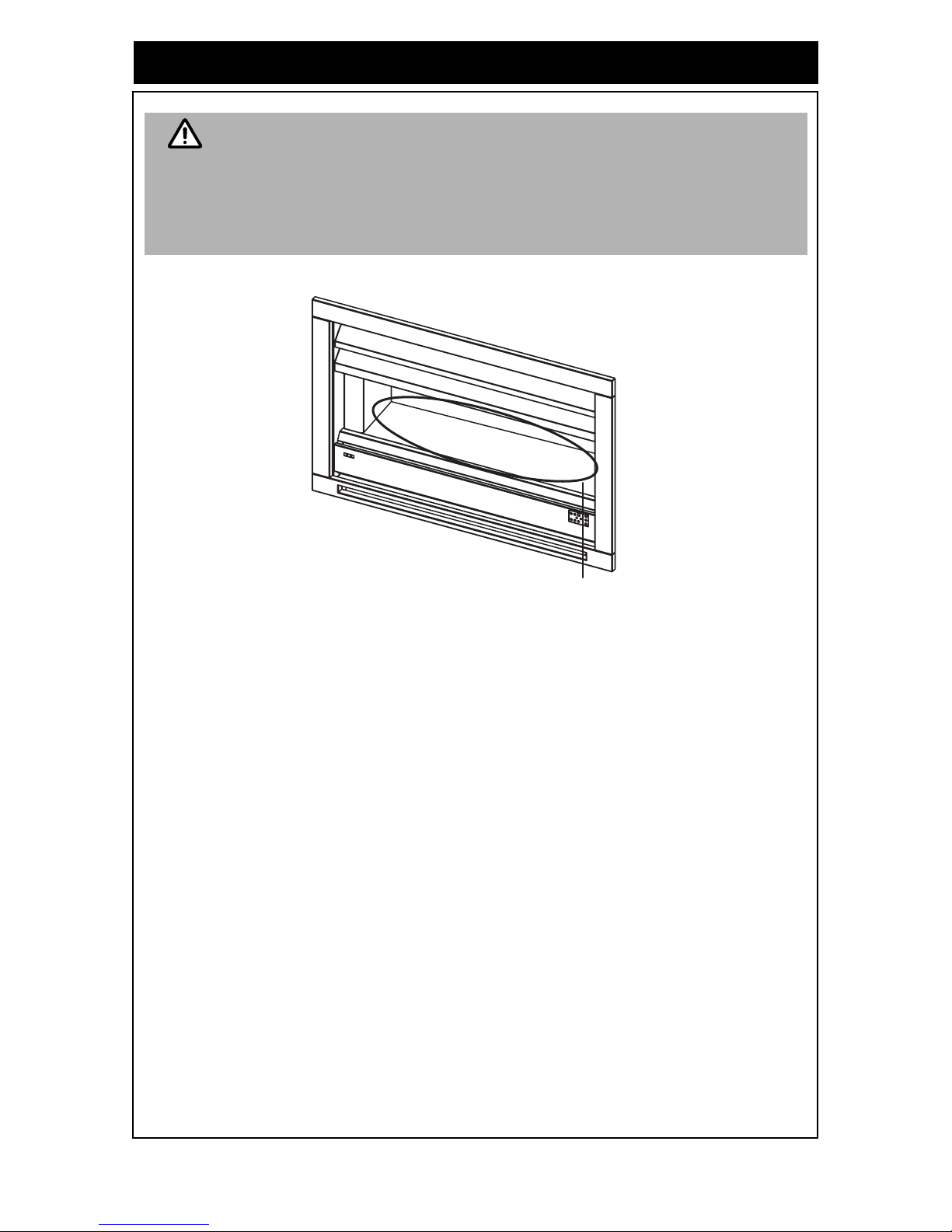
SAFETY POINTS
• The combustion chamber area becomes very hot during operation.
• Ensure young children or the infirm do not gain access to the combustion
chamber or components whether the appliance is in operation or not.
• To reduce the risk of fire or injury from burns and for t he pr otect ion of young
children or the infirm a secondary guard is recommended.
• The secondary guard is not supplied with this appliance and may be
purchased by the owner.
WARNING
Combustion
Chamber area
Page 9

Rinnai Australia - 9 - Constellation 800/1000 Operation Manual
OPERATION
Failure to comply with these instructions could result in a fire or explosion which could
cause serious injury, death or property damage.
Improper installation, adjustment, alteration, service or maintenance can cause
property damage, personal injury or loss of life. Such work must o nly be performed by
an Authorised person.
When using the Constellation Flame Fire for the first time or after long periods of non
use, ignition may not occur the first time due to a ir in the gas pipes. If ignition does not
occur after approximately 30 seconds the unit will cease operation automatically. Try
operating the unit again if this occurs.
The Constellation Flame Fire may make noises after ignition or extinction. This is due
to expansion and contraction of the internal components and is normal.
The Constellation Flame Fire will not ignite if the ‘ON/OFF’ button is pressed
straight after extinction. After approximately 20 seconds has passed the unit will
automatically go into ignition mode.
OPERATION USING THE CONTROL PANEL
The control panel is located on the bottom right hand
side of the front panel of the Constellation Flame Fire.
TURNING THE CONSTELLATION ‘ON’
Press and release the 'ON/OFF' button. The ignition
sequence will commence and the Power indicator LED
will illuminate. The pilot burner will ignite first, followed by the
main burner.
TURNING THE CONSTELLATION ‘OFF’
Press and release the 'ON/OFF' button. This will extinguish all flames and the Power indicator
LED will go out.
ADJUSTING THE FLAME
Two flame settings are available, Low and High.
Pressing the ‘Flame Up’ button will increase the flame. Pressing the ‘Flame Down’ button will
decrease the flame.
ADJUSTING THE FAN
Three fan settings are available, Off, Low and High. The fan operates independently from flame
adjustment.
Pressing the 'Fan Up' button will operate the fan at 'High' spee d. The 'Fan Hi' indicator LED
on the control panel will illuminate.
Pressing the 'Fan Down' button once will operate the fan at 'Low' speed. The 'Fan Low' indicator
LED on the control panel will illuminate.
Pressing the 'Fan Down' button a second time will switch the fan off. The 'Fan Low' indicator
LED on the control panel will go out.
OPERATION USING THE REMOTE CONTROL
The remote control emits an Infra Red (IR) signal and must be aimed at the receive unit located on
the control panel on the bottom right hand side of the front panel . The normal operating range is
approximately 5 metres, up to an angle of approximately 40 degrees to the horizontal. This range
may vary depending on the installation and the strength of the remote control batteries.
USING THE TIMER
Pressing the 'Timer' button on the remote control will activate the timer. The Power indicator
LED will flash and the appliance will now operate for 30 minutes after which it will switch 'off'
automatically. Pressing the 'timer’ button again within the 30 minute period this will cancel the
timer and the Power indicator LED will stop flashing. Whilst operating in timer mode all other
functions are available.
NOTE
NOTE
1
+
+
-
-
17
2
36
4
5
8
9
1
2
1 2
8 9
6 4
7
5
7 5
3
4 2
4
2
Page 10

Rinnai Australia - 10 - Constellation 800/1000 - Operation Manual
CARE AND MAINTENANCE
CONSTELLATION FLAME FIRE OPERATION CHARACTERISTICS
Before asking for a service call please check the following characteristics.
These characteristics are part of the normal operation of the appliance and do not indicate a fault.
TROUBLE SHOOTING CHECK LIST
Use the following chart to help determine whether a service call is required. If you are unsure about the operation
contact Rinnai Australia, or your local agent.
CHARACTERISTIC EXPLANATION
At ignition:
Smoke or smells are produced on the first start up
operation after installation or after an extended
period of non-use.
This is caused by a film of oil on the heat exchanger
from manufacture or dust. This will stop after a short
time.
Clicking noises during ignition or when the flame
setting is changed.
This is noise caused by expansion and extraction of
hot parts and is normal.
Fault Condition
Probable Cause
No ignition or control
panel indicators
Burners fail to ignite
Combustion stops
during operation
Smell of gas
Remote control
does not operate
Possible Remedy
Gas escape 1.Turn off gas at the meter or LP gas cylinder.
2. Extinguish any open flame.
3. Open windows.
4. Do not touch electrical switches.
5. Do not use the a telephone in the building in which the
unit is installed.
6. Contact your gas supplier from a neighbours telephone
or use a mobile phone away from the building in which
the unit is installed.
Not plugged in or turned on
Plug in power cord or press the control panel On/Off button
Air in gas pipe
Re-attempt operation after power is restored.
Mains power failure Re-attempt operation a number of times.
If appliance will not operate contact Rinnai.
Louvres obstructed
Remove the obstruction from louvres.
Gas supply turned off
Turn gas supply on at meter or cylinder.
Flat batteries
Replace the remote control batteries 4 x 1.5v (AAA).
Remote control incorrectly aimed
Change operation position of remote control & try again.
CLEANING
Unplug the power cord before cleaning. All external parts of the
Constellation Flame Fire and remote control can be cleaned
using a soft, damp cloth and a mild detergent, except for the
combustion chamber.
DO NOT clean internal areas such as the combustion chamber.
The combustion chamber area MUST NOT be cleaned as indicated by
SERVICE
Rinnai recommend that this appliance be serviced every 2 years. If the power cord or any other component of
the Constellation Flame Fire is damaged, they must be replaced by Rinnai service staff or a suitably qualified
person. Any service or repair work should only be carried out by an Authorised person. Rinnai has service and
spare parts departments nationally. See back page for contact details.
Service calls for general cleaning, maintenance and wear and tear are not
necessarily covered under the warranty and may be chargeable.
Combustion
Chamber
WARNING
NOTE
Page 11

Rinnai Australia - 11 - Constellation Model 800/1000 - Installation Manual
INSTALLATION GENERAL ......................................................................................12
PRODUCT SPECIFICATIONS .................................................................................12
INSTALLATION CONSIDERATIONS ......................................................................13
MANTLES .................................................................................................................14
DECORATIVE SURROUND FRAMING DIMENSIONS ............................................15
GAS SUPPLY ...........................................................................................................15
FLUE REQUIREMENTS ...........................................................................................15
STEPS FOR INSTALLATION ...................................................................................16
INSTALLATION PROCEDURE .................................................................................17
BLACK COALS / RIVER STONES PLACEMENT ....................................................18
TESTING PROCEDURE............................................................................................19
TO CHECK AND SET BURNER PRESSURES ........................................................19
DIMENSIONS ............................................................................................................21
INSTALLATION AND COMMISSIONING CHECKLIST ............................................23
INSTALLATION / GAS FITTER DETAILS .................................................................23
CONTACTS ...............................................................................................................24
INSTALLATION MANUAL
Page 12

Rinnai Australia - 12 - Constellation Model 800/1000 - Installation Manual
INSTALLATION GENERAL
PRODUCT SPECIFICATIONS
Models: Constellation 800 / Constellation 1000 CONB (Black) / CONSS (Stainless Steel)
General
description:
Inbuilt Radiant Decorative Effect Gas Flame Fire with natural draught flue
system
Gas input rate: Model 800 Model 1000
Natural Gas Propane Natural Gas Propane
High: 30 MJ/hr 30 MJ/hr 40 MJ/hr 38 MJ/hr
Low: 18 MJ/hr 18 MJ/hr 24 MJ/hr 24 MJ/hr
Burner pressure: High: 0.95 kPa 2.00 kPa 0.87 kPa 2.10 kPa
Low: 0.35 kPa 0.72 kPa 0.34 kPa 0.85 kPa
Data plate: On base panel to the right hand side of gas control
Gas control: SIT modulating gas valve
Burners: Intermittent pilot burner and Ceramat® main burner
Warm air
discharge:
Top louvres
Gas connection: 1/2” BSPT male union
Flue terminal: Natural draft round top discharge flue
Inner - 200 mm Diameter
Outer - 250 mm Diameter
Power supply: 230 ~ 240V 50 Hz. Unit is supplied with 3 pin, 10 Amp plug and supply lead,
replace only with Rinnai Australia P/N. 90182065 and Rinnai NZ P/N. 6765B.
Fan: Tangential 2 speed, power rating 60 Watts
Combustion
system:
Ceramat® burner
Black Coals /
River Stones:
Ceramic
Ignition system: Continuous spark intermittent pilot ignition system
Operation: Soft touch buttons and remote control to light pilot and burners
Safety devices: Overheat thermal cutout switch / flame sensors
Combustion
method:
Naturally aspirated burner
Installation type: Inbuilt only
Weight: Constellation 800
Constellation 1000
65 kgs
70 kgs
Flue
requirement:
A minimum vertical flue length of 3.6 m is required.
A minimum of 1.2 m of vertical flue is required before any bends or offsets.
A maximum of two 45° bends may be used.
The manufacturer reserves the right to change or modify specifications without notice.
Ceramat® is a registered trademark of SCHOTT AG gas burner systems, Germany.
• Improper installation, adjustment, alteration, service or maintenance can
cause property damage, personal injury or loss of life.
• Installation and service must be performed by an Authorised person.
WARNING
Page 13

Rinnai Australia - 13 - Constellation Model 800/1000 - In stallation Manual
INSTALLATION GENERAL
INSTALLATION CONSIDERATIONS
2. The Constellation Flame Fire is not suitable for installation in a bathroom or toilet.
3. The installation of the flue system must comply with the requirements of AS 5601 / NZS 5261.
Only Rinnai Decorative Flue components are compatible with the Constellation Flame Fire.
Rinnai Decorative Flame Fire flue component s com prise a flue terminal kit, extension lengths to
make 3.6 m of flue lengths flue mounting plate and connecting collar. Available as an additional
to the standard kit is a 45 degree offset kit. Examples of flue configurations as shown.
Detailed Flue installation instructions are included with the flue terminal kits.
Installation considerations are as follows:
1. The Constellation Flame Fire is designed to
be installed into a decorative surround. This
surround may be constructed of combustible
timber framework with plaster sheeting or
similar materials. The Flame Fire panels
remain cool enough to be in direct contact
with combustible surfaces.
A decorative surround may also be
constructed of masonry brickwork similar to
that used to construct conventional
fireplaces.
Console Installa tio ns with
Direct Vertical Flue
All installations must use the
Rinnai flue system designated for
the Constellation Flame Fire.
The design of this flue is incompatible with most
existing masonry fireplaces. For this reason it is
normally not practical to install the Constellation
Flame Fire into existing masonry fireplaces.
The decorative surround can encompass the
Flame Fire with the flue pipe exposed in the room
(“Console Installation”) or can encompass both
the Flame Fire and flue pipe provided clearance
requirements between flue pipe and decorative
surround material are met (“False Fireplace
Installations”). Refer to the diagrams.
False Fireplace Installations with
Offset Through the Wall
False Fireplace Installations with
Direct Vertic al Flue
NOTE
Page 14

Rinnai Australia - 14 - Constellation Model 800/1000 - In stallation Manual
INSTALLATION GENERAL
4. Since the Constellation Flame Fire is a decorative effect appliance, the space in which the unit
is installed must have adequate fixed ventilation compliant with the requirements of AS 5601.
For Decorative Gas Log Fires this requires that one or more openings with a combined free
ventilation area of not less than 314 cm² (31400 mm²) shall be provided for each appliance.
Notes regarding ventilation: *
The opening may be provided by any of the following options, provided that there is a ventilation path to
outside that is unobstructed by building material or insulation:
i. a) Directly through an outside wall (preferred option).
b) Through to an outside wall but offset.
c) Into a cavity ventilated to outside.
d) Into an underfloor space ventilated to outside.
e) Into a roof space ventilated to outside.
5. The Constellation Flame Fire comes
supplied with power cord and 3 pin plug
passing through the insulating bush in the
lower right hand side of the rear panel as
shown. This is suitable for plugging into a
10A earthed power point if this power
point is accessible to the end user with
the appliance in the installed condition.
This power point must not be located
above the appliance. If the power supply
is to be concealed, the appliance can be
directly hard wired by an Authorised
electrical tradesperson with an isolating
switch accessible to the end user with the
appliance in the installed condition. Refer
to AS 3000 and AS 5601 for details.
6. The Constellation Flame Fire must not
be installed where curtains or other
combustible materials could come into
contact with it. In some cases, curtains
may need restraining.
See diagram for minimum clearances
required.
MANTLES
A mantle is allowable providing that it conforms
to the dimensions and clearances shown.
* Derived from AS 5601 - 2005.
POWER CORD
INSULATING BUSH
300 mm
1000 mm
300mm
300 mm
300 mm minimum
500 mm
from top glass
50 mm Maximum
at 300 mm above
150 mm maximum
Page 15

Rinnai Australia - 15 - Constellation Model 800/1000 - In stallation Manual
INSTALLATION PROCEDURE
DECORATIVE SURROUND FRAMING DIMENSIONS
The Constellation Flame Fire must be placed on a solid hearth placed under the
appliance. This hearth must be capable of supporting the appliance. Material such as
cement sheet or medium density fibreboard are suitable examples. The height of this
hearth must be added to any framing dimensions shown.
For successful installation the framing dimensions must be strictly adhered to.
GAS SUPPLY
The gas supply to the appliance must be positioned as shown in
the framing dimensions and should terminate 145 mm back from
the front face of the appliance.
Gas pipe sizing must consider the gas input to this appliance as
well as all other gas appliances in the premises. The gas meter
and regulator must be specified for the total gas rate. An approved
sizing chart such as the one in AS 5601 should be used.
Purging the Gas Supply
All foreign materials such as filings must be purged from the gas
supply, as they may cause the gas control valve to malfunction.
FLUE REQUIREMENTS
The Constellation Flame Fire flue system is a 'twin wall flue'
system as defined in AS 5601 with a 200 mm inner wall diameter
and 250 mm outer wall diameter. As such, the clearance between
the outer wall and combustible surfaces must be a minimum of 25
mm to conform with the requirements of AS 5601.
There is no limit to the height of the flue, however, the vertical
height from the appliance flue sp ig ot to th e 'o ff se t' (if used) must
be at least 1.2 metres.
Only one 'offset' can be used (2 x 45 degree bends).
The minimum vertical flue height must be at least 3.6 m.
NOTE
A
C
B
Hearth
E
F
D
Hearth
450 mm
Model 1000:
-1000 mm
Model 800:
- 800 mm
136 mm
665 mm
+ Hearth
Height
104 mm
+ Hearth
Height
450 mm
Framing and Gas Pipe Entry Dimensions
A
B
C
E
D F
145 mm
Appliance
Pipe
COMBUSTIBLE MATERIAL
FLUE
Inner wall
Outer wall
50mm from inside
>
must be
25mm from outside
>
must be
B
E
F
O
R
E
A
N
Y OFFSET OR
B
E
N
DS
MAXIMUM
2 X 45° BENDS
MINIMUM VERTICAL HEIGHT 3.6 m
'OFFSET'
MINIMUM VERTICAL HEIGHT 1.2 m
Page 16

Rinnai Australia - 16 - Constellation Model 800/1000 - In stallation Manual
INSTALLATION PROCEDURE
STEPS FOR INSTALLATION
1. Determine the preferred location of the Constellation Flame Fire. Check roof space for any flue
obstructions.
2. Construct the decorative surround in accordance with the Framing Dimensions.
3. Install the flue in accordance with the Instructions supplied with the flue terminal taking note of the
following:
a. Flue termination above the roof must comply with AS 5601.
b. Vertical flue height must be no less than 3.6 metres.
c. The vertical height from the appliance to the first 45 degree bend must be at least 1.2 metres.
d. A maximum of 2 x 45 degree bends may be used.
e. The inner and outer flue pipes must be supported independently of the flame fire and the flue
installation guide in accordance with AS 5601.
4. Run the gas supply. For pipe sizing, use a gas pipe sizing chart such as the one in AS 5601.
The gas supply pipe should be run leaving a ½” BSP socket connection at the position shown on
Framing Dimensions.
5. Purge the gas supply of air and debris. All foreign materia ls such as filings must be p urged from the
gas supply as they may cause the gas control valves to malfunction.
6. Prepare and install the appliance as follows:
(Refer Diagram 1).
a. Place the appliance on a flat surface.
b. Remove the two screws from the bottom
horizontal edge of the applian ce surround .
Lift the appliance surround to disengage
from the two clips on the top horizontal edge.
c. Pull appliance surround away from
appliance.
d. Remove the four screws holding the front
panel assembly in place.
e. Disconnect the Communication Cable from
the rear of the remote control sensor .
f. Remove the two screws holding the Flue
Cover Assembly in place. Remove the
flue cover assembly to provide access for
flue attachment.
g. Remove the flexible gas hose and reducing
flare from the packaging carton. Ensure that
the hose, flare and gas supply pipe are free
of damage and debris. Attach flexible gas
hose pipe and reducing flare to the BSP
connection of the gas regulator assembly.
(Refer Diagram 2).
h. Slide the appliance into the decorative
surround, whilst routing the flexible gas hose
through the supply access opening at the
rear on the left hand side as shown. Ensure
no components are damaged during this
process. Use the two levelling screws
fastened by locknuts in the base at the front
of the appliance to level and stabilise the appliance.
i. Connect appliance to the electrical supply.
This applies only if the appliance is direct wired.
2
3
4
6
6
5
NOTE:
DECORATIVE FASCIA ONLY
COMES WITH CONSTELLATION
BLACK MODEL
5
1
DIAGRAM 1
1
1
2
3
Q
Q(1:4)
305
P
138
P(1:4)
1/2"BSPT MALE UNION
DIAGRAM 2
4
Page 17

Rinnai Australia - 17 - Constellation Model 800/1000 - In stallation Manual
INSTALLATION PROCEDURE
Installation Continued
j. Slide the appliance into the decorative surround,
whilst routing the flexible gas hose through the
supply access opening at the rear on the left hand
side as shown. Ensure no components are
damaged during this process. Use the two levelling
screws fastened by locknuts in the base at the front
of the appliance to level and stabilise the
appliance.
k. When the appliance is stable and level fasten it
against the decorative surround using the two
holes on each front flange (four holes in total).
l. Attach the flue pipe to the appliance flue spigot in
accordance with the Flueing Installation
Instructions.
m. Attach the flexible gas supply hose from the
appliance to the ½" BSP socket connection on the
gas supply pipe.
7. Fit the two stainless steel side reflectors by placing
the right and left reflector brackets on the burner tray
support with the top angle section facing upwards as
shown.
8. To re assemble carry out the above in the reverse
order.
• Ensure the power supply to the appliance is isolated.
A gas leak test must be carried out in accordance with AS 5601. Use a soapy
solution on all gas connections. Leaks will be visible when the soapy solution
forms bubbles. When finished wipe the soapy solution off with a rag.
WARNING
Fastening
holes
NOTE
Top
Top
Top
Left
Reflector
Top
Right
Reflector
6
6
6
Page 18

Rinnai Australia - 18 - Constellation Model 800/1000 - In stallation Manual
BLACK COALS / RIVER STONES PLACEMENT
• Remove 2 bags of Black Coals / River Stones (24 pieces) and 2 bags of granules from the
accessory box.
• Stack 18 pieces of Black Coals / River Stones evenly in two rows of 9 pieces each
(Approx. Gas 15 mm) on top of Ceramat® Burner as shown in Diagram A.
• Place all the granules evenly on top of the Ceramat® Burner in the space between the Black Coals /
River Stones. Avoid pouring the granules directly onto the Ceramat® Burner as this may cause
blockage and poor combustion. Take care not to drop the Black Coals / River Stones on the Base
Panel, which contains Electronic Components.
• Stack the remaining 6 Black Coals / River Stones on top of the bottom layer of Black Coals / River
Stones as shown in Diagram B.
• Whilst placing the Black Coals / River Stones take care not to damage the
Ceramat® Burner.
• Do not operate the appliance if you observe any damage to the Ceramat®
Burner during installation or after use.
• A damaged Ceramat® Burner could be dangerous. The Bur ner may need to be
replaced.
• DO NOT operate the Constellation without either the Bla ck Coals and/or River
Stones in place.
• Use ONLY the Black Coals / River Stones provided.
• DO NOT use heat beads or any other materials. Ensure to advise Customer of
this.
DO NOT FORGET TO PLACE GRANULES.
• Place granules evenly on top of the Ceramat® Burner in the space between
the Black Coals / River Stones. Other materials must not be used.
WARNING
NOTE
CONSTELLATION
CONSTELLATION
CONSTELLATION
CONSTELLATION
Page 19

Rinnai Australia - 19 - Constellation Model 800/1000 - In stallation Manual
TESTING AND COMMISSIONING
TESTING PROCEDURE
TO CHECK AND SET BURNER PRESSURES
•
Refer to Data Plate and the Technical Specification section in this manual.
• Connect the CAT5 Cable to the control receiver in the rear right hand side of the front panel
assembly. Don’t fit front panel assembly to the appliance yet.
• Loosen the outlet test point screw and attach manometer to the test point. The outlet test point is on
the right hand side of gas control (shown below).
• Turn the appliance ‘ON’. Adjust to the ‘high’ flame setting. Check the high pressure setting adjust as
detailed below. Adjust to the ‘low’ flame setting. Adjust as detailed below if required.
If adjustments are necessary, remove Cap C. The pressure adjustment screw and nut are on th e front side of the
gas control as shown and should be set to the pressures on the appliance data-plate.
• After chec king the pressures, turn the applian ce off, remove manometer and tighten the test point
screw.
• Turn the appliance on and off a few times to confirm correct ignition and operation.
• When satisfied that the appliance is igniting and operating correctly, refit the burner cover assembly
and front panel assembly.
• Refit the flame fire surround.
• If the Constellation will not operate correctly, refer to the Trouble Shooting section on page 10.
• It may take approximately 2 hours of operation for the black coals/river stones to achieve their full
flame pattern and glow.
• During the initial burn in period, some smoke and smell may be emitted. The appliance should be
run on the high position in a well ventilated room until these dissipate.
• Installation and commissioning must be carried o ut by an Authorised person.
• Wiring inside this appliance may be at 240 V potential.
• Do not test for gas escapes with an open flame.
High Pressure Setting:
• Use a 10 mm spanner to turn nut A. Turning
clockwise increases the outlet pressure whilst
turning anti-clock wise decreases the outlet
pressure.
Low Pressure Setting:
• Turn off the power to the POV by disconnecting
the POV test connection in main harness and
keeping Nut A stationery.
• Use a screwdriver for setting Screw B. Turning
clockwise increases the outlet pressure whilst
turning anticlockwise decreases the outlet
pressure.
• Replace Cap C after pressure adjustments.
• Reconnect the POV test connection.
• Burner aerations are factory preset and cannot
be adjusted.
To ensure the correct operation of the POV it is necessary that the plastic Cap C
is returned to its original location.
WARNING
C: CAP
INLET
TEST POINT
OUTLET
TEST POINT
GAS
OUTLET
B: LOW PRESSURE
ADJUSTING SCREW
A: HIGH PRESSURE
ADJUSTING NUT
GAS CONTROL AND IGNITION PACK ASSEMBLY
WARNING
Page 20

Rinnai Australia - 20 - ConstellationModel 800/1000 - Installation Manual
TESTING AND COMMISSIONING
INSTALLATION AND COMMISSIONING CHECKLIST
•
Complete the Installation Check list and the installer details on page 23.
• Instruct customer on Constellation operation.
• Ensure the customer understands the content of this booklet.
• Ensure this booklet is left with the Customer.
Ensure the Customer understands that:
• The Constellation Flame Fire has no primary guard and therefore the Safety
Instructions on pages 6 and 7 must be followed to prevent the risk of injury from
burns.
• No part of this appliance should be permanently removed.
• Paper or other material must not be burnt in this appliance.
• Young children and the infirm should be supervised at all times.
WARNING
Page 21

Rinnai Australia - 21 - Constellation Model 800/1000 - In stallation Manual
DIMENSIONS
CONSTELLATION 800 and CONSTELLATION 1000
(Note: All Dimensions are in mm)
All Models Black Models Stainless Steel Models
MODELS A B
CONSTELLATION 800 790 825
CONSTELLATION 1000 990 1025
400
20
660
253
1
0
4
358
494
358
C
L
POWER CORD
INLET
GAS SUPPLY
INLET
32
136
Page 22

Rinnai Australia - 22 - Constellation Model 800/1000 - In stallation Manual
WIRING DIAGRAM
If the power cord is damaged or requires replacing, it must be replaced by the manufacturer or the
manufacturer’s agent or similarly qualified person in order to avoid a hazard. The power cord must
only be replaced with a genuine Rinnai spare part.
12
11
10 9
8
7
6
Modulating Coil
(Gas Contr ol)
Sparker Earth
Flame Rod
Sparker
54 231
1
2
PN 10659
ISSUE: A
HI
LO
–
++
–
CONTROL PANEL RECEIVER
CONTROL UNIT
IGNITION PACK ABC 537 SIT
FAN MOTOR
OH SWITCH
1
2
2
1
ACTIVE
NEUTRAL
AC 230V -240V
50 Hz
HI
LO
2
3
4
1
FUSE 3A 250V
(BN)
(GN)
(GN)
(RD)
(YW)
(YW)
(GY)
(GY)
(BK)
(BE)
(RD)
(BE)
(WE)
(BN)
(BN)
(BE)
(GN)
BNYWRDGYBKBEWE
GN
=BROWN
=YELLOW
=RED
=GREY
=BLACK
=BLUE
=WHITE
= GREEN
CABLE CAT 5
WIRING DIAGRAM IBOF
NEUTRAL
ACTIVE
LOW
HIGH
IGN
RESET
MOD
NEUTRAL
1
2
(BN)
(RD)
(BE)
(WE)
(BN)
(BN)
(BN)
(BE)
(BK) (BK)
1
2
FLAME ROD
TEST CONNECTION
POV TEST
CONNECTION
Page 23

Rinnai Australia - 23 - Constellation Model 800/1000 - In stallation Manual
(To be completed by the Installer)
Models: (Constellation 800 / Constellation 1000)
Serial No: _______________________________
NO YES
1. Has a gas leak test procedure been carried out?
2. Was a Rinnai flue system installed in accor dance with the
instructions?
3. Have specified gas pressures been checked and set?
4. Are the black coals / river stones located correctly?
5. Have ember granules been placed and free of dust and
powder?
6. Has the appliance been test fired for correct operation?
7. Is the end-user fully aware of operation and safety
issues?
Company name: ____________________________________________________
Installers name: ____________________________________________________
Address: ____________________________________________________
____________________________________________________
____________________________________________________
Phone: __________________ Mobile: __________________________
Certificate of Compliance / Certification Number:__________________________
(* where applicable)
Authorised Persons – Licence Number: _______________________________
Signed
:________________________ Date:___________________
INSTALLATION / COMMISSIONING CHECKLIST
INSTALLERS / GAS FITTER DETAILS
Page 24

24 Constellation Model 800/1000 RA TSD Issue No. 2 05-021 - 28/08/07
Head Office
10-11 Walker Street,
Braeside, Victoria 3195
P.O. Box 460
Tel: (03) 9271 6625
Fax: (03) 9271 6622
National Help Line
Spare Parts & Technical Info
Tel: 1300 555 565*
Fax: 1300
300 141*
*Cost of a local call Higher from mobile or public phones.
Australia Pty. Ltd.
ABN 74 005 138 769
Internet: www.rinnai.com.au E-mail: enquiry@rinnai.com.au
Internet: www.rinnai.co.nz E-mail: sales@rinnai.co.nz
Head Office, New Zealand
691 Mt. Albert Road,
Royal Oak, Auckland
P.O. Box 24-068
Tel: (09) 625 4285
Fax: (09) 624 3018
24 Hour Service
Tel: 0800 746624 (0800 Rinnai)
CONTACT INFORMATION
 Loading...