

Rinnai 37AHA04508KA5, 37AHA06012KA5, 37AHA07514KA5, 37AHA09016KA5 Installation, Operation And Maintenance Manual
37AHA SERIES
HYDRONIC AIR HANDLER
SIZES 045 THRU 090
Installation, Operation, and Maintenance Manual
Consumer Safety Information................................ 2
Overview of the Rinnai Hydronic Air Handler........ 3
Model Number Nomenclature ...............................3
Physical Data......................................................... 4
Receiving & Checking Equipment......................... 5
Installation
Clearances .................................................... 5
Locating and Mounting............................... 6-9
Plumbing.................................................10-13
Electrical Connections............................14-16
Dip Switch Options...................................... 17
Thermostat Installation........................... 17-18
Start-Up Procedure ..................................... 19
Troubleshooting...................................... 20-23
Sequence of Operation .................................. 24-26
Maintenance.................................................. 26, 27
Selection Guide............................................. 27, 28
Specifications ...................................................... 29
Air Delivery Performance .................................... 30
Accessories......................................................... 31
Hydronic Air Handler Output..........................32-34
Wiring Diagrams............................................. 35-37
Parts List......................................................... 38-39
Limited Warranty ............................................40-41
To register your hydronic air handler or tankless water heater,
please visit www.rinnairegistration.com
.
Quality Assurance
This product is manufactured in a
facility registered by UL to ISO 9001.
File No. A6887.
UL recognized
component
2100-500
Consumer Safety Information
SAFETY DEFINITIONS
Indicates safety alerts. When this symbol is seen on the Hydronic Air Handler and in all instructions
and/or manuals, be alert to the potential for personal injury. Recognize signal words DANGER,
WARNING, and CAUTION. These words are used with the safety alert symbol.
DANGER
WARNING
CAUTION
NOTICE
SAFETY CONSIDERATIONS
Before any work is undertaken, it is imperative to
observe all precautions as stated in this manual, on
tags, and/or labels, together with any other safety
measures that may apply.
Indicates an imminently hazardous situation which, if not avoided, will result in death or
serious injury.
Indicates a potentially hazardous situation which, if not avoided, could result in death or
serious injury.
Indicates a potentially hazardous situation which, if not avoided, could result in minor or
moderate injury. It may also be used to alert against unsafe practices.
This is used to highlight important information which will aid in installation, improve
reliability or enhance operation.
• Wear safety glasses and work gloves.
• When practical, objects to be brazed shall be
moved to a designated safe location or, if the
objects to be brazed cannot be readily moved, all
movable fire hazards in the vicinity shall be taken
to a safe place, or otherwise protected.
• Use quenching cloth for all brazing and un-brazing
operations.
• Suitable fire extinguishing equipment shall be
immediately available in the work area and shall
be maintained in a state of readiness for instant
use.
WARNING
Before installing or servicing the Hydronic Air Handler,
always turn off all power to unit. There may be more
than 1 disconnect switch. Electrical shock can cause
personal injury or death.
CAUTION
Failure to follow this caution may result in personal
injury. Sheet metal parts may have sharp edges or
burrs. Use care and wear appropriate protective
clothing.
Read these installation instructions carefully and
adhere to all WARNINGS and CAUTIONS. Consult
local building codes, Occupational Safety & Health
Administration (OSHA) and National Electrical Code
(NEC) for special requirements.
Improper installation, modification, service,
maintenance, or use of Hydronic systems can cause
electrical shock, burns or other conditions which may
cause personal injury or property damage. Consult a
qualified installer, service agency, or your distributor
for information or support. The qualified installer or
agent must use factory authorized kits and/or
accessories when installing this product. Refer to the
appropriate Rinnai® literature for listing.
Read the entire instruction manual before starting the installation.
2
NOTICE
Application of this Hydronic Air Handler should be
indoors. Special attention should be given to unit
sizing and piping, filling, and purging.
Rinnai Corporation Hydronic Air Handler Manual

Overview of the Rinnai Hydronic Air Handler
INTRODUCTION:
The optimum in hydronic technology: the newly
designed Rinnai® multi-position Hydronic Air Handlers
offer a unique solution for a wide variety of small and
medium sized residential and light commercial
applications. They are compact and ready to fit in tight
spaces which may include, but not limited to, attics,
basements, closets, crawlspaces, and utility rooms.
The 37AHA units are equipped with an intelligent
microprocessor control that allows for domestic hot
water priority and adapts to available hot water flow for
space heating by automatically regulating the pump
and blower sequence to maximize comfort.
These unique Hydronic Air Handlers are designed to
work in combination with our line of Rinnai® tankless
products to deliver a wide variety of heating capacities
that cover the entire residential and light commercial
heating spectrum.
Because our units are designed specifically to the
Rinnai® tankless products, our stated capacities are
fine tuned and are based on the “Air Handler / tankless
water heater” match set and NOT a given water flow
rate.
CODES AND STANDARDS:
It is the responsibility of the installer to follow all
national codes, standards and local ordinances, in
addition to instructions laid out in this manual. The
installation must comply with regulations of the local
building, heating, plumbing, and other codes. Where
local codes are not applicable, the installation must
comply with the national codes and any and all
authorities having jurisdiction.
The following is a suggested list of codes and
standards for the United States and Canada:
General Installation
Installation of Air Conditioning and Ventilating Systems
NFPA 91 (latest edition)
Duct Systems
Sheet Metal and Air Conditioning Contractors National
Association (SMACNA)
American Society of Heating, Refrigeration, and Air
Conditioning Engineers (ASHRAE)
2001 Fundamentals Handbook Chapter 34 or 2000
HVAC Systems and Equipment Handbook Chapters 9
and 16
US and CANADA: Air Conditioning Contractors
Association (ACCA) Manual D
Acoustical Lining and Fibrous Glass Duct
US and CANADA: current edition of SMACNA; NFPA
90B as tested by UL Standard 181 for Class I Rigid Air
Ducts
Electrical Connections
US: National Electrical Code (NEC) ANSI/NFPA 70
(latest edition)
CANADA: Canadian Electrical Code CSA C22.1
(latest edition)
Plumbing Systems:
US and CANADA: ICC International Plumbing Code
(IPC); Uniform Mechanical Code (UMC); Uniform
Plumbing Code (UPC)
Model Number Nomenclature
37AH A 045 08 K A 5
Model
37AH - Multi-speed Hydronic Air Handler
Series
Denotes a major design change in the
product line (i.e. capacity)
Nominal Heating Capacity (BTU/h)
045 = 45,000
060 = 60,000
075 = 75,000
090 = 90,000
Cooling / Heating Air Flow Range (CFM)
08 = 800 (650-800)
12 = 1200 (650-1200)
14 = 1400 (1000-1600)
16 = 1600 (1200-1750)
Multi-position
5 = Yes
2 = No
Engineering Digit
Denotes minor change
(not present in sales or service
literature)
Voltage Code (V-Ph-HZ)
K = 115 - 1 - 60
L = 240 - 1 - 50 (export models)
Rinnai Corporation Hydronic Air Handler Manual 3
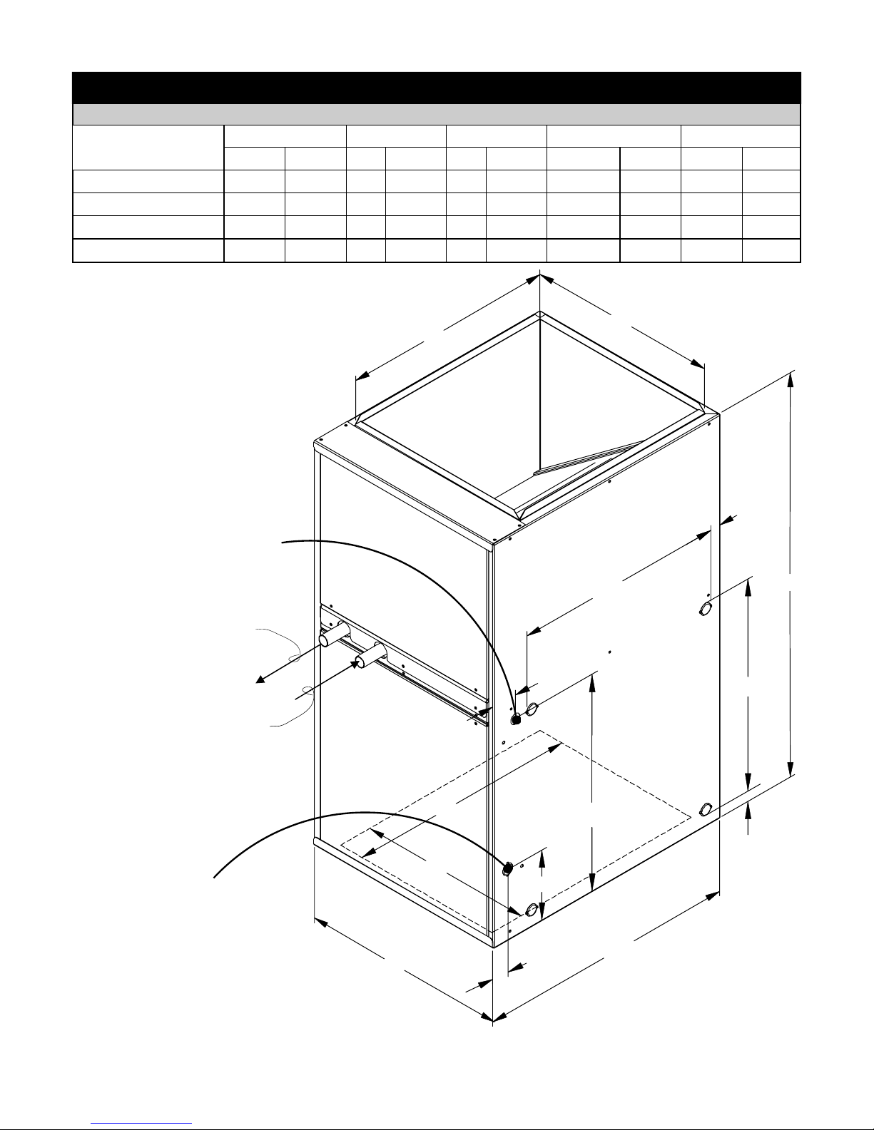
Table 1 - Physical Data
DIMENSIONS
UNIT SIZE
37AHA04508KA5 14 355.6 18 457.2 12 304.8 10 - 1/2 266.7 19 482.6
37AHA06012KA5 17 -1/2 444.5 18 457.2 16 406.4 16 - 11/16 423.9 19 - 1/4 489.0
37AHA07514KA5 21 533.4 18 457.2 20 508 18 - 11/16 474.7 19 - 1/2 495.3
37AHA09016KA5 24 - 1/2 622.3 18 457.2 24 609.6 21 - 1/8 536.6 19 482.6
A B C D E
in. mm in. mm in. mm in. mm in. mm
C
B
7/8” Dia. KO Thermostat Wire
Entry (Typ. for both sides)
Water Out
Water In
7/8” Dia. KO Supply
Power Wire Entry
(Typ. for both sides)
1"
17 13/16"
34"
21/8"
17 13/16"
E
18 5/16"
1"
D
6"
4
A
13/8"
22"
Figure 1
Rinnai Corporation Hydronic Air Handler Manual
Receiving and Checking Equipment
IDENTIFY UNIT
The unit model number and serial number are stamped
on the unit identification / name plate (located on the
top right side of unit). Check this information against
shipping papers and job requirements.
INSPECT SHIPMENT
Upon receipt of a 37 Series Hydronic Air Handler the
packaging should be checked for peripheral sign s of
transportation damage while unit is still in the shipping
package. If unit appears to be damaged or is torn
loose from its anchorage, the unit shall be immediately
examined by the receiving party before removal. If
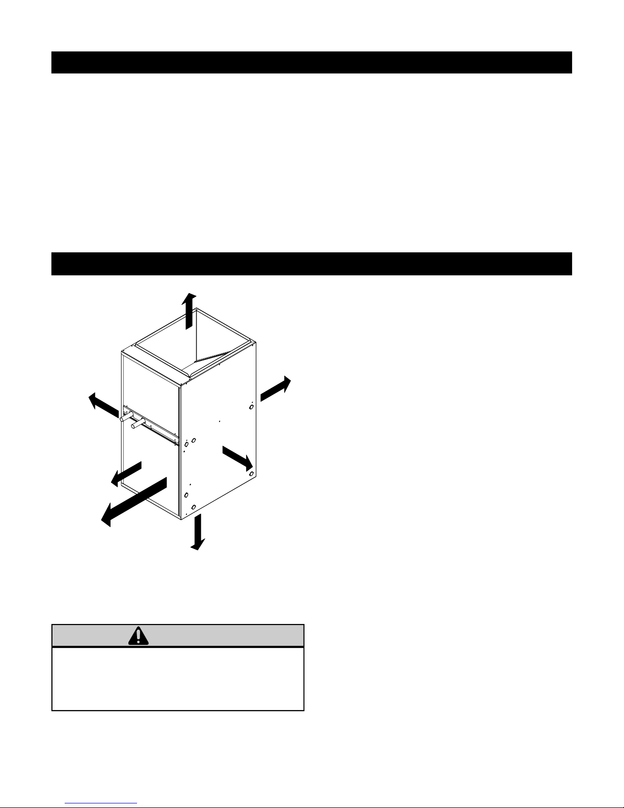
Installation
TOP/PLENUM
zero
BACK
SIDE
zero
zero
damage is found, the receiving party must sign the
driver’s delivery receipt noting all damage (i.e. carton
damage and/or product damage) as well as contact the
last carrier immediately, preferably in writing,
requesting inspection by the carrier’s agent. All claim
papers MUST be forwarded to Rinnai® America
Corporation for processing. In general, upon receipt of
product, be sure to check all items against shipping list;
if items are found to be missing, it should be noted as
such on the driver’s delivery receipt; and the receiving
party shall also immediately notify the area
distributor. To prevent loss or damage, leave all parts
in original packages until installation.
The 37AHA Series hydronic Air Handler needs to be
installed and commissioned by a knowledgeable
qualified professional.
NOTES:
1. This Air Handler is approved for upflow, downflow,
and horizontal configurations.
2. Clearance arrows do not change with Air Handler
orientation.
FRONT
zero
SERVICING
24” (610 mm)
BOTTOM
zero
SIDE
zero
Figure 2: Minimum Clearance to Combustible
Construction
WARNING
Do not install this unit if the unit is damaged.
Do not install this unit if any part or all of unit has been
under water. Refer to the Receiving and Checking
Equipment section.
3. This Air Handler is for indoor installation only.
4. Unit(s) shall be installed in such a way as to
ensure that the electrical components are
protected from any contact with water.
5. Unit(s) shall not be installed directly on any
combustible material other than wood flooring.
6. This unit is designed to be used with an air
distribution system (ductwork). Refer to the Air
Distribution Ductwork section.
7. The installer shall provide ample space for
servicing and cleaning. Always comply with
minimum fire protection clearances shown in
Figure 2.
8. The 37AHA units are designed to be installed
vertically or horizontally on the floor; units may
also be hung from the ceiling or wall. Be sure to
allow appropriate clearances for wiring, piping,
and servicing.
Rinnai Corporation Hydronic Air Handler Manual 5

Installation
LOCATING AND MOUNTING THE HYDRONIC AIR
HANDLER
General
The multi-position 37AHA Series Hydronic Air
Handlers are shipped in packaged configuration. This
means that the units may be installed without
assembly and/or modifications when configured for
bottom return air inlet application; however, some
modifications and assembly are necessary if units are
to be installed in an application that requires side
return air inlet arrangement. For instructions on
required modifications and assembly refer to Figures 3
and 4.
17 15/16"
NOTE: For side return application, obtain Side Filter
Rack” and “Bottom Fill Plate from your area
authorized Rinnai® distributor.
CUT SIDE RETURN OPENING
IN UNIT USING THE (4)
LOCATING KOCKOUTS
21 11/16"
3/8"
USE EXISTING SCREW HOLE
TO LOCATE FILTERRACK
Figure 4: Side Filter Rack Installation
17 3/4"
1/8"
23/16"
SIDE FILTER
INSTALL RETURN BLANK OFF
PLATE (BOTTOM FILL PLATE)
AHA045: P/N 603000011
AHA060: P/N 603000012
AHA075: P/N 603000013
AHA090: P/N 603000014
RACKASSEMBLY
P/N 603000015
Figure 3: Modification of Unit to Accommodate
Side Filter Rack Installation
6
SHARED UNIT SCREW
USE TO LOCATE
FILTERASSEMBLY
Rinnai Corporation Hydronic Air Handler Manual
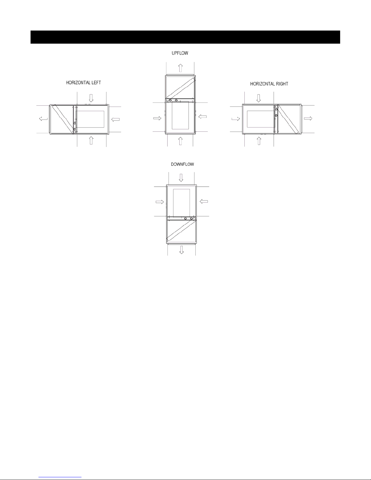
Installation
Blower located below coil
section. Conditioned air is
discharged upward.
Blower located to the right of
coil section. Conditioned air is
discharged to the left.
Figure 5: Multi-Position Orientation
Upflow Installations
The 37AHA Hydronic Air Handler is ready to install in
the up-flow position without modifications.
The unit MUST be supported on the bottom ONLY and
set on a field supplied supporting frame or plenum.
Supporting frame or plenum must be anchored to the
unit and to the floor or wall.
Blower located to the left of coil
section. Conditioned air is
discharged to the right.
Blower located above coil
section. Conditioned air is
discharged downward.
Downflow Installation
The 37AHA Hydronic Air Handler is ready to install in
the down-flow position without assembly or
modifications when configured for bottom return air
inlet installation. If side return air inlet installation is
desired refer to Figures 3 and 4.
Horizontal Left and Right Installations
The 37AHA Air Handlers are shipped without a bottom
fill plate. If side return installation is desired, the return
opening (Bottom) must be blanked off. If a bottom fill
plate is required, install only a factory authorized
bottom fill plate. Refer to the Rinnai Accessory list for
details. For side filter rack installation instructions
refer to Figures 3 and 4.
Without Cased Coil:
If a cased coil is NOT being installed, the cabinet can
be placed on either side for horizontal airflow as
shipped, when configured for bottom return air inlet
installation. If side return air inlet installation is desired
refer to Figures 3 and 4.
With Cased Coil (Field Supplied):
Refer to the manufacturer’s Cased Coil installation
instructions for details.
Rinnai Corporation Hydronic Air Handler Manual 7
Installation
CLOSET INSTALLATION (RETURN AIR THRU
OPENING OR GRILL)
The 37AHA Hydronic Air Handler can be installed in a
closet on a supporting stand or be mounted from the
closet wall using the closet as the return air plenum.
Unit should be high enough from the floor to provide
unimpeded return air flow into the bottom of the
cabinet.
Closet return air opening can be on the front (in closet
door), side (thru the wall) or a combination of both,
providing there is clearance on the sides between
unit’s cabinet and closet. Refer to ACCA Manual D or
SMACNA for sizing and free area recommendations.
NOTE: Local codes may limit application of systems
without a ducted return to single story dwellings.
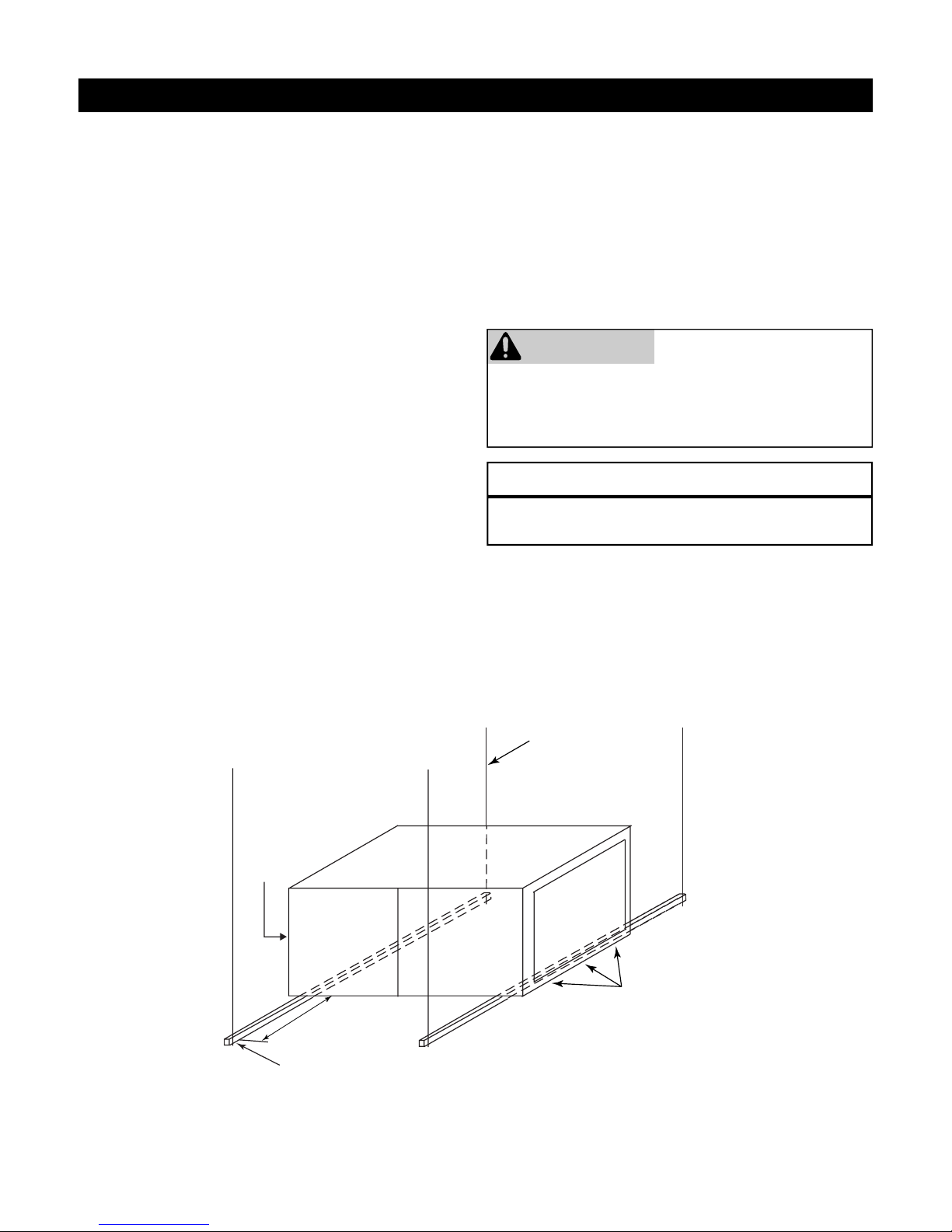
SUSPENDED CABINET INSTALLATION
If the cabinet cannot be supported on a frame or
supported from the wall, it may be suspended.
Use metal strapping or threaded rod with angle iron
supports under cabinet for support. These supports
MUST run parallel with the length of the cabinet (see
Figures 6 and 7).
IMPORTANT: When a 37AHA unit is matched with an
evaporative type (cased coil/condensing unit) split
system for cooling application and the system is
installed above a finished ceiling and/or an occupied
space, building codes may call for a secondary
insulated condensate pan (by others) to be installed
under the entire unit. In other instances, some local
codes may allow the running of a separate, secondary
condensate line in lieu of the required drain pan. It is
the responsibility of the installer to consult local codes
for compliance.
WARNING
It is the installer’s responsibility to use an appropriate
hanging method capable of supporting the unit’s
weight. Refer to the specification section of this
document for the respective unit’s installed weights.
NOTICE
For seismic hanging requirements, refer to local
codes.
Ensure that there is adequate room to remove service
and access panels after installing supporting brackets.
If an auxiliary drain pan is required, the support is to
be placed under a drain pan. In such installations the
unit will need to be supported on vibration isolators
(rubber or Styrofoam blocks).
DOOR
ASSEMBLY
8” MIN FOR
DOOR REMOVAL
(2) HEX NUTS, (2) WASHERS & (2)
LOCK WASHERS REQ. PER ROD
1/4” THREADED ROD
(4 REQUIRED)
SECURE ANGLE
IRON TO BOTTOM
OF AIR HANDLER
WITH 3 #8 x 3/4”
SCREWS TYPCIAL
FOR 2 SUPPORTS
USE 1” SQUARE, 1-1/4 x 1-1/4 x 1/4
ANGLE IRON OR EQUIVALENT
8
Figure 6: Horizontal Unit Suspension
Rinnai Corporation Hydronic Air Handler Manual
Installation
Attachment Methods Using Straps
Method 1
Use (4) #8 x 3/4 sheet metal screws for each strap.
The straps should be vertical against the Air Handler
sides and not pull away from the Air Handler sides.
Method 2
Fold all straps under the Air Handler and secure with
(4) #8 x 3/4 sheet metal screws (2 screws at the side
and 2 screws at the bottom. (Care must be taken not
to drive the screw through the coil.)
1 INCH x 22 GAUGE
GALVANIZED STRAPS
TYPICAL FOR 4 STRAPS
RETURN AIR
OPENING
DOOR
ASSEMBLY
AIR DISTRIBUTION SYSTEM
Existing Ductwork
It is the responsibility of the installer to inspect all
previously installed air distribution system to determine
its suitability for the new heating and/or cooling
system. Existing ductwork may have to be modified
and/or insulated to provide satisfactory air distribution.
Ductwork Installation
Connect the supply-air duct over the outside of 3/4-in.
flange on the unit’s discharge side. Secure the duct to
the flange with proper fasteners for the type of duct
used. Support the duct independently.
Use flexible connectors (if desired between the
ductwork and the unit to prevent transmission of
vibration.
Use insulation with vapor barrier for ductwork passing
through unconditioned spaces.
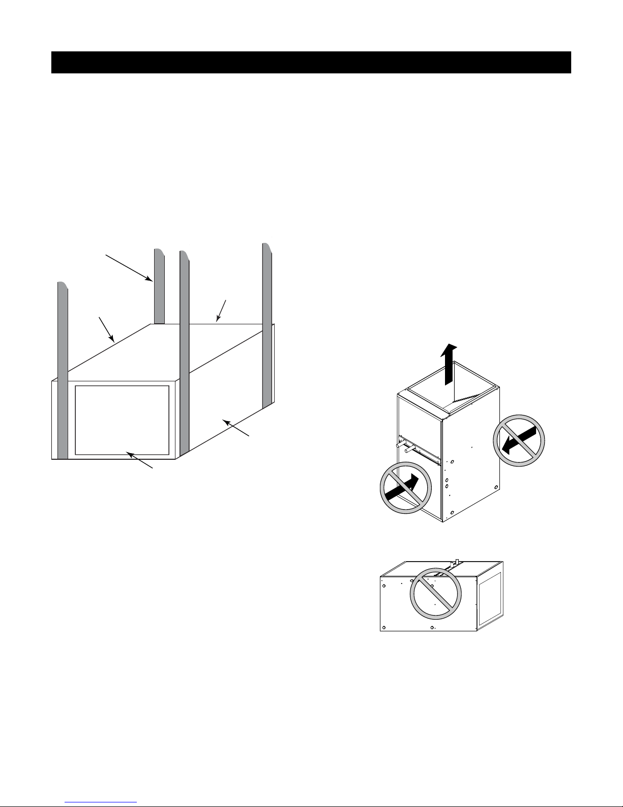
PROHIBITED INSTALLATIONS
COIL
INTERFACE
AREA
BACK OF AHU
SUPPLYAIR OPENING
Figure 7: Horizontal Unit Suspension with Straps
DUCT CONNECTIONS
Supply Duct
The supply ductwork must be attached to the outside
of the flange on the air discharge end of unit. Flexible
connectors may be used if desired.
Return Duct
The return ductwork should be attached to the air
return side (bottom or side) of unit using sheet metal
screws or other fasteners.
For side return air inlet installation see the Figures 3
and 4.
FILTER INSTALLATION
Internal filter rack and a 1 inch disposable filter are
standard on all models. Refer to the Specifications
section for dimensions.
Back
Front
Figure 8:
The air inlet is not allowed to be at
the front or back of the Air Handler
Figure 9:
Do not position the Air Handler on
its back or with it face down.
NOTE:
Multiple Air Handlers configured for installation with a
single Rinnai Tankless Water Heater is prohibited.
Rinnai Corporation Hydronic Air Handler Manual 9

Installation
PLUMBING
Codes:
Observe all local sanitary codes when installing water
lines. The water supply mating connection to the
37AHA Hydronic Air-Handling Units are made via the
two (3/4 in. Dia. X 2-1/2 in. Long) copper stubs to the
front-left of the unit labeled “WATER IN” and “WATER
OUT” (see Figure 1). Mating connectors to be two
field supplied 3/4 in. FNPT-sweat ends or two fieldsupplied 3/4 in. SharkBite type FNPT-push fitting ends
or equivalent.
All associated hydronic piping MUST comply with ICC,
UPC and any other local codes or ordinances having
jurisdiction. USE POTABLE GRADE COPPER
PIPING AND BRASS APPURTENANCES ONLY.
NOTE: Recommended piping, fittings, valves and
other appurtenances (exclusive of those indicted as
accessories that are available through Rinnai
distribution) called for in piping schematics to be fieldsupplied.
Flow Sensor Installation:
(Required for Open Loop Systems)
Care must be taken to ensure that the flow sensor is
not damaged due to excessive tightening. The torque
must not exceed the maximum limit stated below. The
installation should be checked to ensure that no
leaking is evident.
Mating connectors to be (2) 3/4” FNPT fittings (field
supplied).
Pipe-work/connector alignment is imperative (avoid
bending stress).
Polytetrafluoroethylene (PTFE) thread seal tape (teflon
tape), or equivalent, is recommended.
Tighten fittings to maximum torque of 15lb/ft (20Nm).
Soldering Copper Tubing:
The common method of joining copper tubing in
hydronic heating systems is soft soldering. Plumbing
codes do not allow solders containing lead to be used
for domestic water service. USE ONLY 95/5 tin/
antimony solder for all piping systems that incorporate
a domestic water supply.
Note: Precautions must be taken during soldering to
avoid debris or solder from lodging in piping
system.
Mechanical Joining of Tubing:
Where used, refer to respective mechanical system
manufacturer’s installation instructions.
Tubing Insulation:
Any tube conveying fluid at a temperature greater than
that of the surrounding air releases heat.
Insulate all accessible hot water lines and associated
valves with material, such as expanded neoprene or
polyurethane 3/8-in. to 1⁄2-in. thick.
Match the pipe sleeve's inside diameter to the pipe’s
outside diameter for a snug fit. Place the pipe sleeve
so the seam will be face down on the pipe. Tape,
wire, or clamp insulation every foot or two to secure it
to the pipe. If taping is desired, use acrylic tape
instead of duct tape.
Copper Tubing Support:
Copper tubing must be properly supported to prevent
sagging or buckling. On horizontal runs with hard
temper tubing, the following maximum support spacing
is suggested:
• 1/2 in. to 3/4 in. tube: 5 feet maximum spacing
• 1 in. to 1-1/4 in. tube: 6 feet maximum spacing
• 1-1/2 in. to 2 in. tube: 8 feet maximum spacing
The above suggested spacing does not account for
extra weight of piping components such as an
expansion tank, etc. When such components are
present the piping should be supported immediately
adjacent to the component.
On vertical runs, copper tubing should be supported at
each floor level or at a maximum of every 10 feet.
Thermal Expansion of Piping:
In all hydronic systems, piping undergoes temperature
swings as the system operates. This causes changes
in the length of the piping due to thermal expansion.
If the piping is rigidly mounted, this expansion can
cause annoying popping or squeaking sounds and in
extreme cases, the piping can even buckle.
To counter expansion movement, design piping
circuits with sufficient elbows, tees or expansion loops
(only used in large systems) or piping supports that
allow the tubing to expand and contract freely.
Another alternative is to install an expansion
compensator fitting capable of absorbing the
movement.
10
Rinnai Corporation Hydronic Air Handler Manual

Installation
Hydraulic Resistance of Fittings, Valves, and Other
Devices:
Before the total hydraulic resistance of a piping circuit
can be found, the individual hydraulic resistances of all
fittings, valves, or other such components must be
determined. One approach is to consider each fitting,
valve, or other device as an equivalent length of
copper tube of the same pipe size (see Table 2).
By using the equivalent length of piping for all
components in the circuit, the circuit can be treated as
if it were a single piece of pipe having a length equal
to the sum of the actual pipe length, the total
equivalent lengths of all fittings, valves, or other
devices. Refer to Figure 10 and the calculation of
equivalent lengths.
Pipe Sizing Considerations:
When selecting a pipe size for a given flow rate, the
resulting average flow velocity should be between 2
and 4 feet per second.
At water flow velocities of approximately 2 feet per
second, flowing water will carry air bubbles along a
vertical pipe. Average flow velocities of 2 feet per
second or higher can draw along air bubbles in a
downward flow. At the above stated velocities air
bubbles shall be routed to an air separator where they
can be collected and discharged from the system.
Use Taco 4900 series air separator, Model 49-075, or
equivalent (field supplied).
Average flow velocities higher than 4 feet per second
could cause flow noise and should be avoided.
Expansion Tanks:
All liquids used in hydronic heating systems expand
when heated. For all practical purposes, liquids are
incompressible. Any container completely filled with a
liquid and sealed from the atmosphere will experience
a rapid increase in pressure as the liquid is heated.
To prevent this from occurring, all closed loop hydronic
systems MUST be equipped with an expansion tank.
Refer to expansion tank manufacture’s instructions for
proper sizing and installation.
Rinnai Corporation Hydronic Air Handler Manual 11
Installation
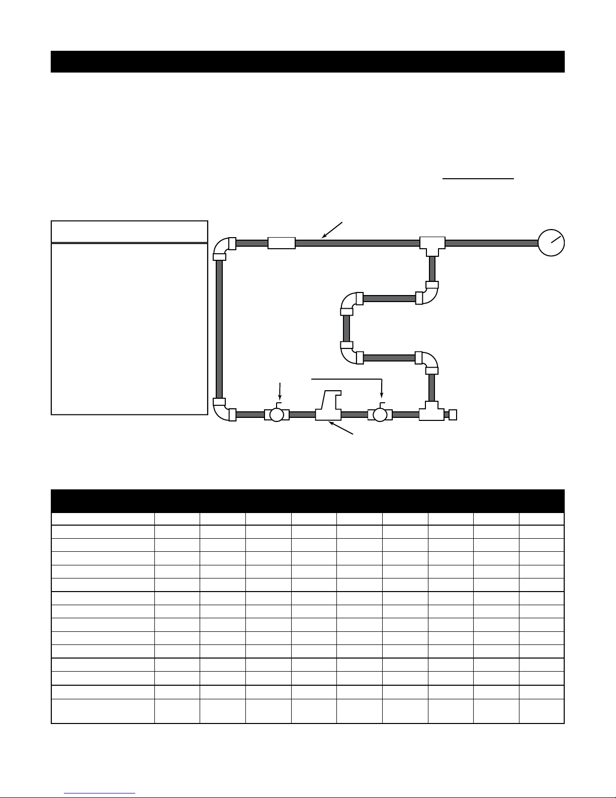
PROCEDURE FOR CALCULATING THE TOTAL
EQUIVALENT LENGTH OF PIPE
Given piping assembly as shown in Figure 10 below,
what is the total equivalent length of the system?
First determine the total straight pipe lengths; next
refer to table 2 to determine the equivalent straight
pipe length for each fitting shown. Add together the
equivalent lengths of piping and fittings.
Rinnai Flow Sensor
NOTICE
Where possible the length of pipe
4 ft
FS
should not exceed 150 feet total
equivalent length.
Any piping running through
unconditioned space MUST be
insulated to prevent heat loss,
and possible freezing of the line.
12 ft
Stickers indicating direction of
flow, (WATER IN, and WATER
OUT) are labeled on the outside
of the cabinet. DO NOT reverse
ball valves
these lines, as this will cause the
unit to malfunction.
¾” Tubing (total straight pipe length)....68 ft.
(6) ¾” 90 deg. Elbows….……..6(2) = 12 ft.
(2) ¾” Side port tee……….…..2(3) = 6.0 ft.
(1) ¾” Taco air separator….1(0.3) = 0.3 ft.
(1) ¾” Rinnai flow sensor.....1(3.2) = 3.2 ft.
(2) ¾” Ball valves….….….....2(2.2) = 4.4 ft.
Total Equivalent length……..……93.9 ft.
3/4 in. type M copper tubing
9 ft
3 ft
10 ft
5 ft
10 ft
3 ft
3 ft3 ft3 ft3 ft
15 ft
cap
gauge
T ACO Model 49-075
Air Separator
Figure 10 Equivalent Length Calculation
Table 2: Equivalent Length of Straight Pipe for Valves and Fittings (ft)
Fitting or Valve 3/8" 1/2" 3/4" 1" 1 1/4" 1 1/2" 2" 2 1/2" 3"
90 deg. Elbow 0.5 1 2 2.5 3 4 5.5 7 9
45 deg. elbow 0.35 0.5 0.75 1 1.2 1.5 2 2.5 3.5
Straight thru tee 0.2 0.3 0.4 0.45 0.6 0.8 1 0.5 1
Side port tee 2.5 2 3 4.5 5.5 7 9 12 15
Reducer coupling 0.2 0.4 0.5 0.6 0.8 1 1.3 1 1.5
Gate valve 0.35 0.2 0.25 0.3 0.4 0.5 0.7 1 1.5
Globe valve 8.5 15 20 25 36 46 56 104 130
Angle valve 1.8 3.1 4.7 5.3 7.8 9.4 12.5 23 29
Ball valve 1.8 1.9 2.2 4.3 7 6.6 14 0.5 1
Swing check valve 0.95 2 3 4.5 5.5 6.5 9 11 13
Flow check valve NA NA 83 54 74 57 177 85 98
Butterfly valve NA 1.1 2 2.7 2 2.7 4.5 10 15.5
Rinnai Flow Sensor NA NA 3.2 NA NA NA NA NA NA
Taco 49-075 Air
NA NA 0.3 NA NA NA NA NA NA
12
Rinnai Corporation Hydronic Air Handler Manual
Installation
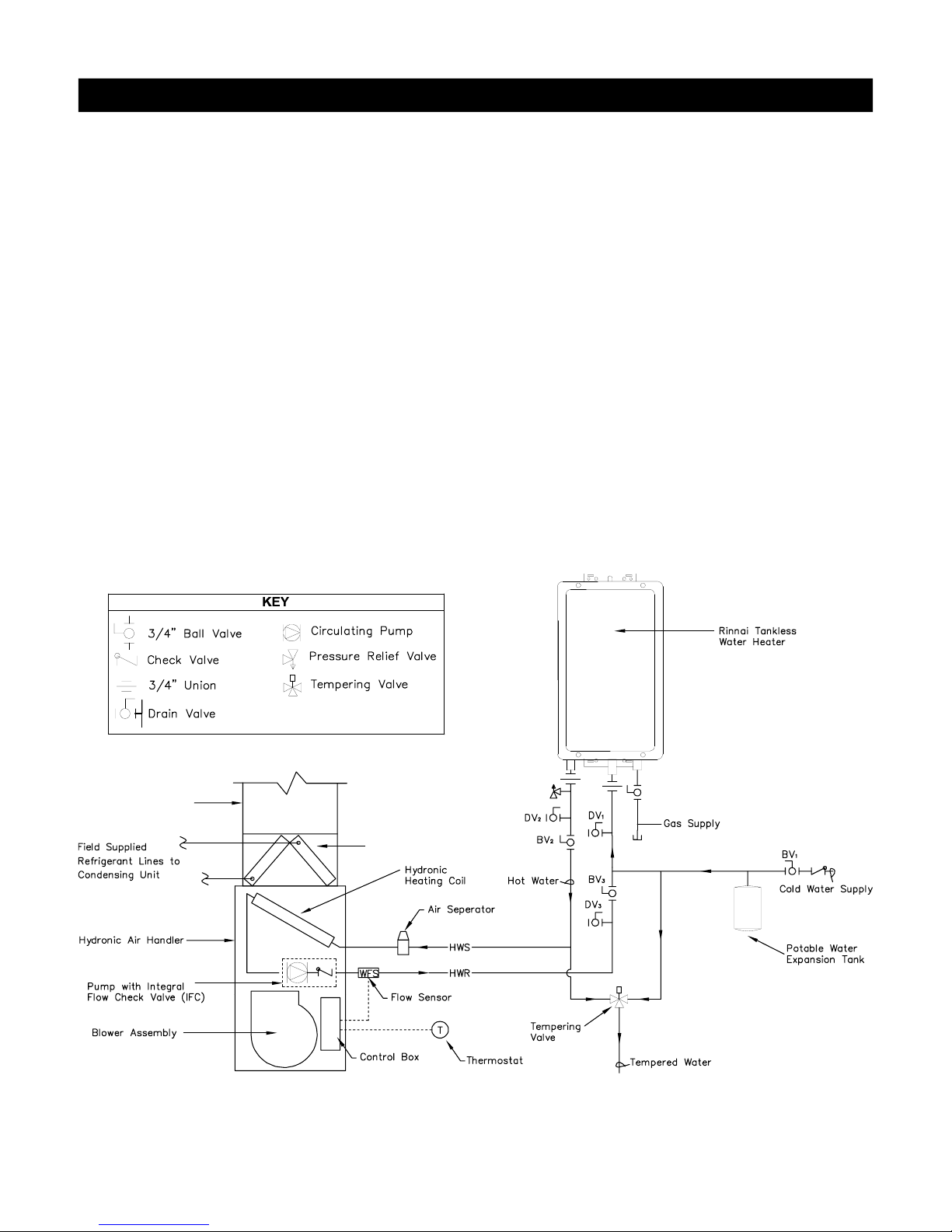
Piping Configuration
When employing a Tankless Water Heater in a
hydronic system, the system is considered an Open
Loop System when configured to simultaneously
deliver both domestic hot water and space heating.
By definition, if the circuit is sealed off from the
atmosphere at all locations (as is true for most modern
hydronic systems) it is called a closed loop system. If
the circuit is open to the atmosphere at any point, it is
called an open loop system. Current Rinnai tankless
products are not certified for closed loop applications.
Open Loop System
If piping is done in accordance with the recommended
schematic diagram shown in Figure 11, the following
purge and priming procedure applies.
PURGING AND PRIMING THE SYSTEM:
The following procedure describes how the Rinnai®
system may be piped to eliminate the need for a
“purge cart” to fill the system and remove entrapped
air bubbles.
STEP 1: CLOSE the air separator venting valve.
STEP 2: CLOSE ball valve 3 (BV
STEP 3: OPEN drain valve 3 (DV
);
3
) to which a hose
3
MUST be connected and draining to a sink, drain or
outdoors.
STEP 4: CLOSE drain valves 1 & 2 (DV
and OPEN ball valve 2 (BV
2
).
and DV 2)
1
STEP 5: OPEN cold water supply main valve (ball
valve 1 - BV
). The system will begin the prime/purge
1
process using the street pressure. Entrapped air
bubbles being pushed out of the system will be evident
by a slight vibration of the discharge hose connected
to drain valve 3 (DV
). The hose will stop vibrating
3
when laminar flow is achieved.
STEP 6: CLOSE drain valve 3 (DV
STEP 7: OPEN ball valve 3 (BV
);
3
). The system is now
3
purged, primed and ready to go.
STEP 8: OPEN the air separator venting valve.
Note: For an open loop system, use expansion tank
approved for potable water use only.
Field Supplied Ducting
(DV)
(BV)
All piping to be 3/4 inch.
Field Supplied
Evaporator Coil
Figure 11 - Typical Piping Arrangement For Dire ct Space Heating and Domestic Water Supply with Tankless
Rinnai Corporation Hydronic Air Handler Manual 13
Installation
ELECTRICAL CONNECTIONS
Line-Voltage Connections:
U.S. INSTALLATIONS: Make all electrical connections
in accordance with National Electrical Code (NEC)
ANSI/NFPA 70 and all local codes or ordinances
having jurisdiction.
CANADIAN INSTALLATIONS: Make all electrical
connections in accordance with Canadian Electrical
Code CSA C22.1 and all authorities having
jurisdiction.
Check all factory wiring per unit wiring diagram and
inspect factory wiring connections to be sure none
were loosened in transit.
WARNING
Before installing or servicing system, always turn off
all power to system. There may be more than 1
disconnect switch. Electrical shock can cause
personal injury or death.
CAUTION
If a disconnect switch is to be mounted on the unit,
select a location where a drill or fastener will not
contact electrical or hydronic components. Electrical
shock can cause personal injury or death.
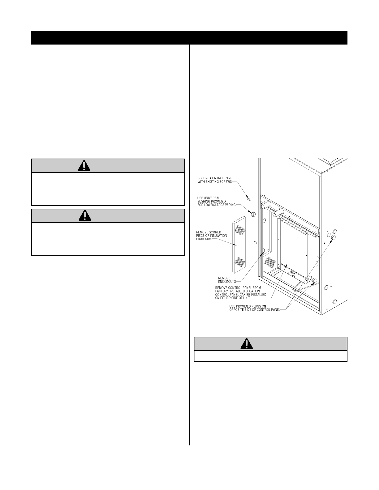
side) follow steps 1 thru 7 below:
1. Remove and keep one screw and cover from the
Control Box.
2. Remove and keep two screws holding Control Box
to casing of 37AHA unit (See Fig. 12.).
3. Remove wire tie from looped wires attached to
Control Box.
4. Before Control Box is reinstalled, remove the
scored piece of insulation from the desired side.
Remove two knockouts in the casing where the
Control Box is to be installed.
NOTE: Prior to making any electrical connections,
ensure that supply voltage, frequency, and phase are
as specified on unit rating plate.
Check to ensure that the existing electrical service is
adequate to handle the additional load imposed by the
Hydronic Air Handler. Refer to unit wiring diagram for
proper electrical connections.
All electrical connections MUST comply with NEC and
any other local codes or ordinances having
jurisdiction. USE COPPER WIRE ONLY. Provide
separate branch electric circuit with field supplied
disconnect switch.
Location of disconnect switch to be in clear site,
accessible and in close proximity to the unit.
Correct polarity MUST be maintained for 115 V wiring.
If polarity is incorrect unit will NOT operate.
Control Box Relocation:
The Control Box is factory installed in the blower
compartment upper left corner (see Figure 12); if
factory location of Control Box is suitable, proceed to
next section. To relocate the Control Box to an
alternate location (blower compartment upper right
Figure 12: Control Box Relocation
WARNING
Do NOT remove ground screw inside control box.
5. Secure Control Box to casing with the two screws
removed and kept from Step 2.
6. Reinstall two plastic plugs (from spare parts bag)
where indicated in openings on adjacent side of
Control Box.
7. Route Control Box wiring within unit away from hot
surfaces, sharp edges and rotating parts.
14
Rinnai Corporation Hydronic Air Handler Manual
 Loading...