

Page 1

Rinnai
Convector
412/314
Unflued Room Heater
CUSTOMER’S OPERATING
INFORMATION
AND
INSTALLATION INSTRUCTIONS
This
appliance shalt be installed in accordance with:
Manufacturer’s Instructions
Local Gas Fitting Regulations.
Rinnai
GAS SPACE
HEATERS
Municipal Building Codes
A.G.A. Installation Code for Gas Burning Equipment.
Any other Relevant Statutory Regulation.
This appliance should be installed, serviced and removed
by an authorised person
R
8
Page 2
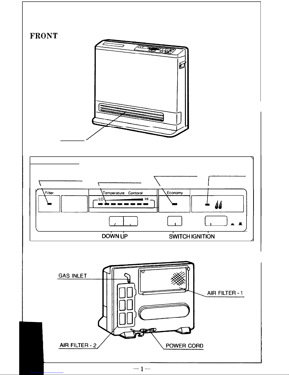
PARTS DESCRIPTION
LOUVRE
CONTROL PANEL
ROOM
ECONOMY COMBUSTION
FILTER
TEMPERATURE SWITCH LAMP
LAMP
WARNING LAMP
INDICATOR
-
\
\
I
I
I
I
ON OFF
rn
\
/
DOkN
U’P
ECONOMY
ShTCH IGNlTlbN
BUTTON
REAR
-l-
Page 3
IMPORTANT POINTS
Unpack heater:
Check for damage. If heater is damaged, contact your supplier for advice. Before
installing the heater, check it is labelled for the correct gas type. Refer to local
gas authority for confirmation of gas type if you are in doubt.
Included in Carton:
Customers Operating Information/ Guarantee
IMPORTANT
1.
2.
3.
4.
5.
6.
7.
8.
The appliance must be installed to the requirements of the local gas authority.
For information on gas rate, see data plate on the appliance.
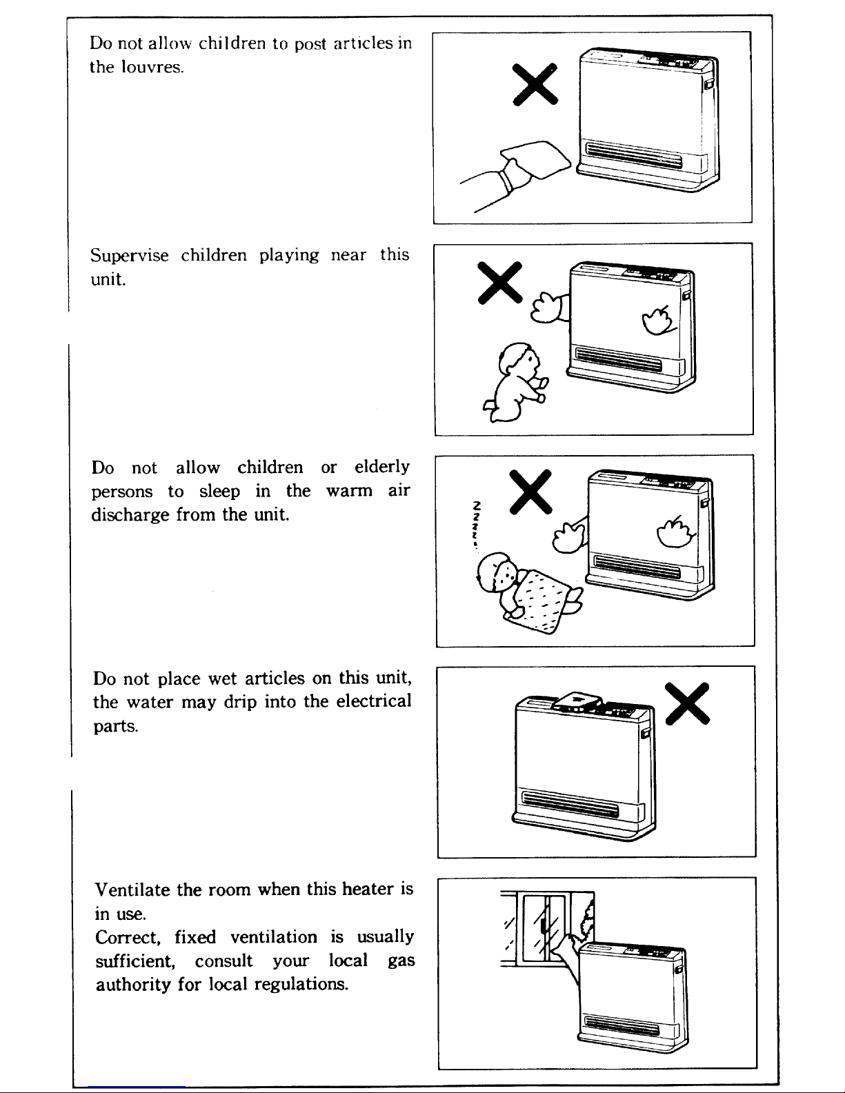
When installing this appliance, ensure that the room is correctly ventilated.
Check AG 601 or the Local Authority for information on ventilation
requirements.
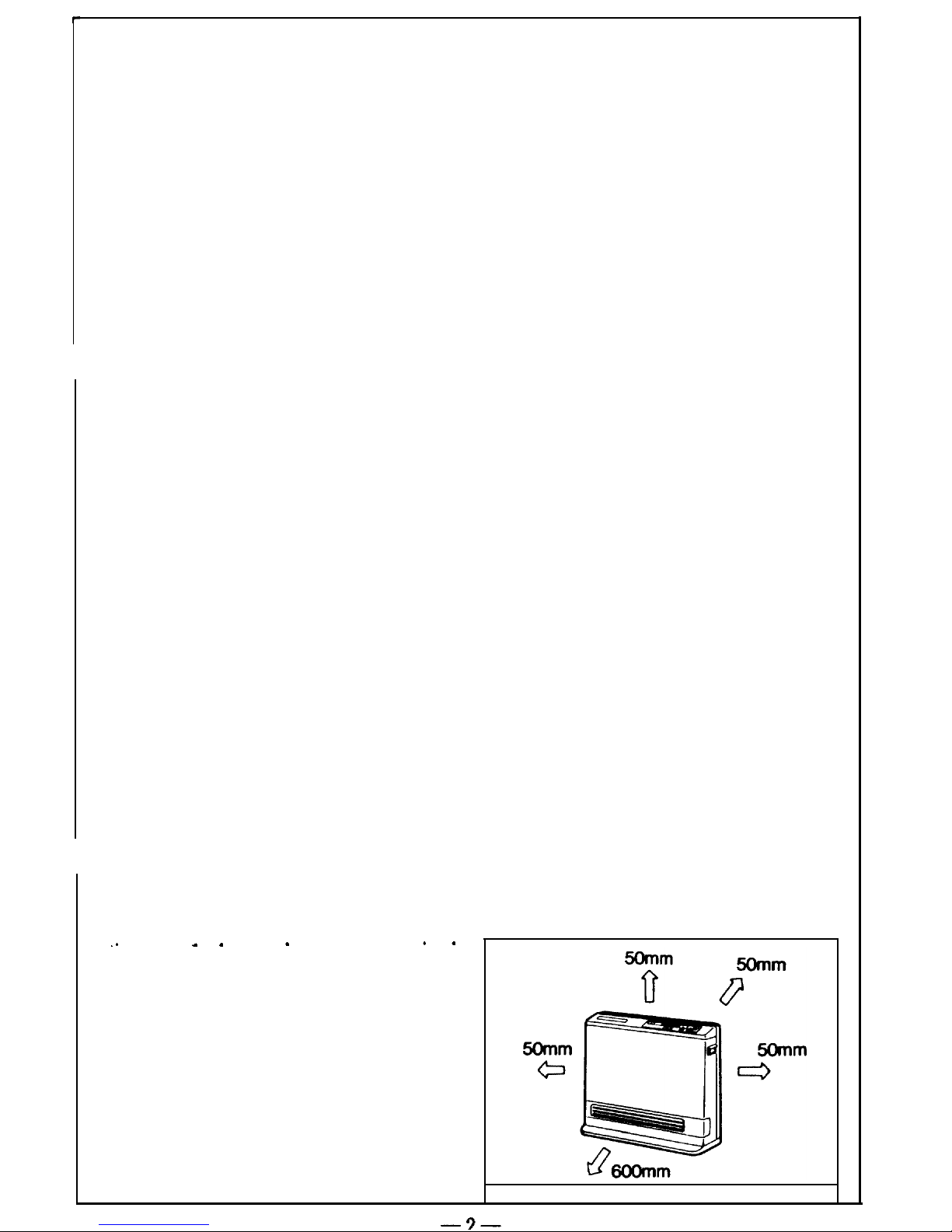
DO NOT install in bedroom or bathroom.
This appliance must not be installed in close proximity to flammable
materials, e.g. curtains, and must be 50mrn clear of side walls.
This appliance is not designed to be built in.
If you move house, check the gas type in the area where you are moving to.
The Local Authority will be able to advise on local regulations.
This heater discharges a large volume of warm air at low level to provide
even heat distribution. If the air in the room contains cooking vapour or
cigarette smoke, and the heater is used on a carpet, the surface of the carpet
may become discoloured.
In addition, some nylon carpets contain dyes which may be affected by the
warm air flow.
Some soft vinyl surfaces are also subject to discolouration by warm air.
To prevent discolouration of carpets etc., a mat should be placed under the
appliance, extending about 750 mm in front of it.
. .
a .
.
. .
Diagram
1 shows clearances required
around this unit whilst it is in operation.
-?-
Page 4
Page 5
Page 6
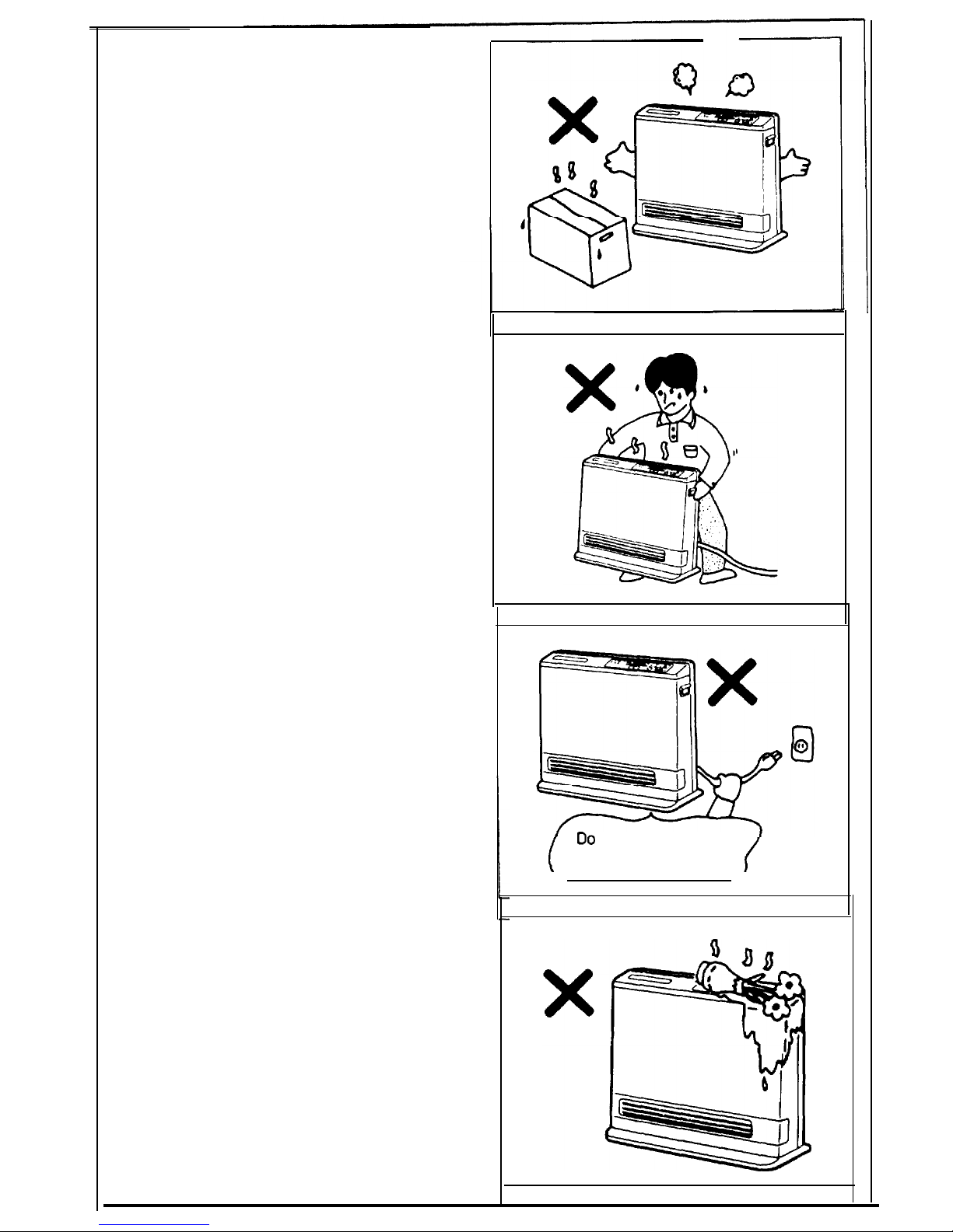
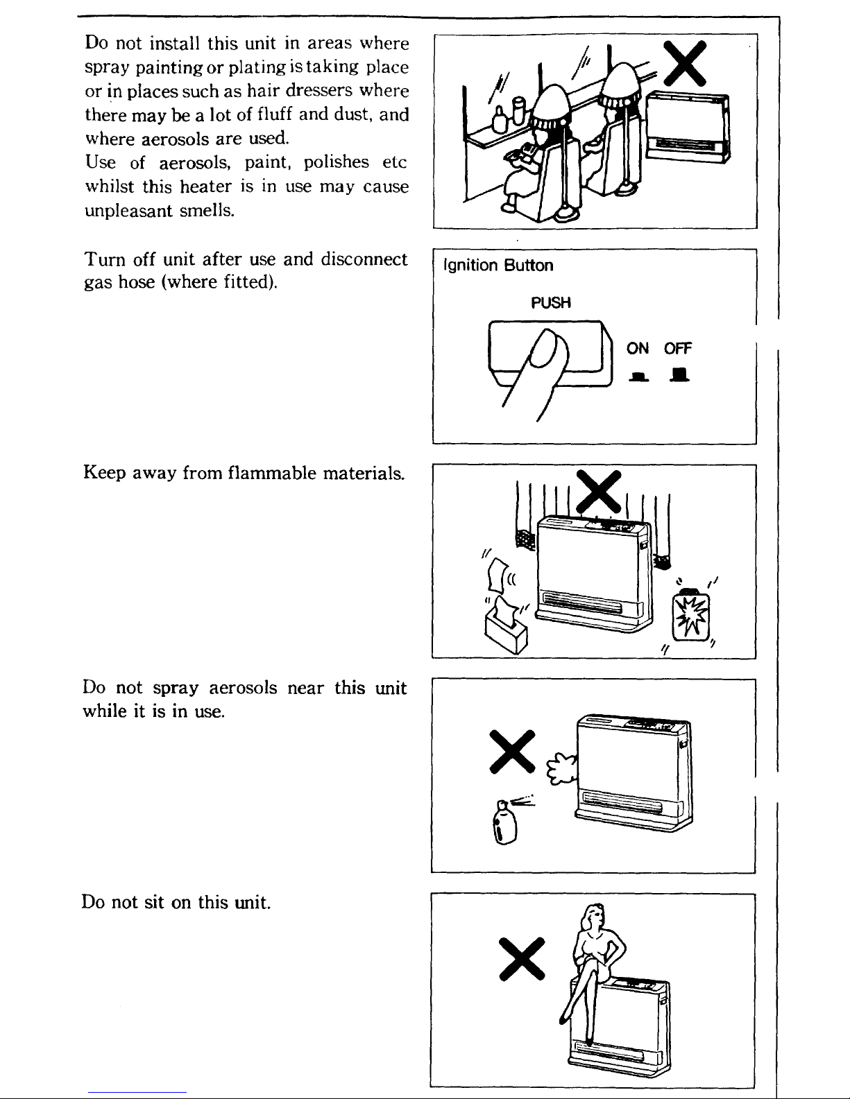
Do not place articles in front of the
louvres.
Do not move the unit whilst it is turned
on.
Do not turn the unit off by unplugging
it from the wall, or whilst the fan is
cooling the unit off.
This unit is not suitable for use with a
plug in type timer.
Do not place containers
top of the unit. Water in
cause extensive damage.
of
liquid on
the
unit can
Do
not unplug
during operation.
Page 7

CUSTOMERS OPERATING
INFORMATION
INSTALLATION
Check room size: This heater must not be installed in a room smaller than 30 m3.
Your Convector 314 is fitted with a flexible lead and bayonet type plug in
fitting, simply plug into your bayonet floor fitting.
Check room size: This heater must not be installed in a room smaller than 42.5
m3.
Your Convector 412 is fitted with a flexible lead and bayonet type plug in
fitting, simply plug into your bayonet floor fitting.
Page 8

CUSTOMERS OPERATING
INFORMATION
INSTALLATION
Check room size: This heater must not be installed in a room smaller then 30 m3.
Your Convector
314 is fitted with a flexible lead and bayonet type plug in
fitting, simply plug into your bayonet floor fitting.
IGNITION
Plug the heater into both the gas and
the power points. Room must be
ventilated when using this heater.
Depress the ignition button slowly and
firmly.
When you release the ignition button
the ‘Temperature Level’ lamps will
illuminate, the spark will ignite the
main burner and the convection fan
will begin to run. If the unit does not
ignite in 15 seconds the spark will
stop and the display will flash. Turn
off and repeat ignition operation.
(See page 7).
,
This heater has an automatic ignition
system, when the main burner has lit,
the combustion indicator will glow, and
the spark will stop.
There may be a smell of burning dust
the first time the heater is lit or when
the heater has been out of operation
for a long time, this is normal. You
may need to repeat the ignition
operation the first time the heater is
plugged in, due to air in the hose.
PUSH
ON OFF
mma
Temperature Level
ROOM TEMP SET TEMP
(Flashing)
(Steady)
Combustion Indicator
Page 9

TEMPERATURECONTROL
The
thermostat
automatically
modulates the burner and the fan to
maintain the room temperature which
you have selected.
To change the room temperature,
simply adjust the temperature control
knob to the desired setting.
The heater will run on high for 1 to 2
minutes after ignition no matter where
the temperature control is set.
The temperature range from LO to HI
is about
12’C
to
36’C.
Temperature
control may be affected by the
positioning of the heater.
Temperature Control
DOWN
UP
CONTROL BUTTONS
ROOMTEMPERATURE
DISPLAY
Temperature
is indicated by the
L.E.D. display on the control panel.
The room temperature is indicated
by the flashing L.E.D., and the set
temperature by the steady L.E.D. When
the set room temperature is reached,
the flashing L.E.D. disappears and the
temperature is indicated by the steady
L.E.D. You will notice the fan speed
changing as the heater modulates to
match the room temperature.
TO TURN
Depress ignition button again.
The switch will return to the “off”
position.
Disconnect hose after use.
Do not turn off by unplugging at the
power-point. Convection fan continues
to run until heater is cool.
The convection fan may start again
after a few minutes to remove residual
heat.
Temperature Level
cld;#~pDmoo
/
\
ROOM TEMP
SET TEMP
(Flashing) (Steady)
I
UNIT OFF
Ignition Button
PUSH
ON OFF
mm
Page 10

ECONOMY SWITCH
1
To change to “Economy Mode”, push
the “Economy” switch, the green lamp
will glow.
30 min after the room temperature
reaches the preset temperature (set with
the thermostat), the Economy Mode, if
set, reduces the temperature by
l”C,
after another 30 min it reduces the
temperature by a further
l’C,’
this is an
energy saving feature. When the heater
is running only on low, the “Economy
Mode” does not operate. It does not
operate if the unit is under capacity for
the room size.
, Economy Mode Lamp
I
Economy Switch
FILTER LAMP
If filter lamp glows during operation
check both air filters for dust. If there
is dust present, clean filters. See section
on care of unit. Turn heater off before
cleaning filters.
Check Both Filters
The filter lamp is not a safety cut off,
so the heater will continue to run with
the light on. Left in this condition the
heater may overheat and shut off
automatically.
1
FILTER - 2
.
Page 11

SAFETY DEVICES
Over Heat Switch
When the heater gets too hot during operation (for example when the filters
or air outlet louvres are blocked) this device turns the gas off automatically.
Remove cause of overheat (clean filters) allow heater to cool, then re-ignite.
Fuse
The electrical circuits are protected by a fuse. When the fuse blows, the
heater will not operate at all. The fuse must be replaced by an authorised
person.
Flame Failure Device
This device automatically cuts the gas supply to the heater in the event of
a gas failure. To restore the gas supply to the heater, turn it off, then follow
the ignition procedure.
Oxygen Depletion Safety Device
If the oxygen level in the room drops below a pre-set limit, this device cuts
the gas supply to the heater. If the oxygen depletion device operates, turn
the heater off, ventilate the room, then follow the ignition procedure to
relight. Heater will not relight until room is fully ventilated.
Tilt Switch
If the heater is knocked over, the tilt switch will cut the gas supply. The
fan keeps running. To restore the gas supply, stand the heater up and
follow the ignition procedure. The tilt switch may also operate if the
heater is jolted or picked up whilst in
operation.
Page 12

CARE OF HEATER
n
Your
Convector
needs very little maintenance, but the following
information will help you to keep it looking good, and working efficiently.
Unplug unit before cleaning.
All parts of the heater can be cleaned using a soft, damp cloth.
Do not use solvents to clean any parts.
Do not spray aerosols in the vicinity of this appliance while
it is in operation.
Do not place articles on or against this appliance.
Do not store flammable materials near this appliance.
AIR FILTERS
n
Clean
both air
filtcrs
at least
once a
week.
Do not wait for filter warning lamp to come on before cleaning filters.
Dusty filters reduce the air flow through the heater and reduce the heater’s
effectiveness.
Do not use the heater with the filter warning lamp on, it may cause the unit
to overheat.
\
FILTER
1
1
FILTER 2
Clean both air filters with vacuum
cleaner at least once a week.
Page 13

RINNAI GUARANTEE OF QUALITY
As a purchaser of a high quality Rinnai product, we provide you with the
following guarantee on your new Convector RCE-412.
FAN
All other parts
FREE LABOUR FREE PARTS
PERIOD PERIOD
1 Year
2 Years
1 Year
1 Year
The benefits conferred by this guarantee are in addition to all other rights and
remedies in respect of the product which you have under the Trade Practices
Act and other State and Territory Laws.
The unit must be installed correctly by an
authorised
person, and the installation
must conform to all local regulations.
The installation must also comply with the instructions supplied by Rinnai.
The unit must be serviced, installed or removed by an authorised person.
No parts or functions should be modified or permanently removed from the unit.
Please Note: general cleaning, maintenance and wear and tear are not
necessarily covered by the guarantee. Calls of this nature may be chargeable.
Your Rinnai Convector 412 has been approved by the Australian Gas Association.
A.G.A.
Approval Number 4589.
Please
keep these instructions in a safe place for future reference.
Pleaserecord below:
Your Retailer:
NAME
ADDRESS
TELEPHONE
Date of Purchase:
Page 14

FAULT FINDING CHART
PROBLEM
NOT PLUGGED IN
AIR IN THE HOSE
WRONG GAS TYPE
OPERATION INCORRECT
LOUVRE IS BLOCKED
DUST ON THE AIR
FILTERS
DUST INSIDE
THE HEATER
ROOM TOO LARGE
is
2
?t
d
*
-
-
-
-
-
-
-
e
-
-
REMEDY
I
I
PLUG THE HEATER IN
I
I
REPEAT IGNITION
PROCEDURE
I
I
SERVICE CALL
I
SEE THE CUSTOMER’S
OPERATING INFORMATION
REMOVE OBSTRUCTION
I
l
I
CLEAN THE AIR
FILTERS
I
I
SERVICE CALL
I
CHECK WITH RETAILER
1
If you need service on your convector please contact the Rinnai office in your
state or your local agent for information.
Page 15

Specification
Dimensions
Dimensions in mm
-13-
Page 16

Specification
Dimensions
Dimensions
in mm
.
- 13-
Page 17

1
WIRING DIAGRAM]
D
a
[
BLOCK
DIAGRAM
1
$
I
I
I
I
-----
-.I
- 14-
Page 18

Page 19

SPECIFICATIONS
Description
:
Convector 412 (RCE-412).
Type:
Forced convection unflued space heater.
Input:
N.G.
-
17
MJ/h
Propane - 17 MJ/h (15 MJ/h
(Vic.))
Gas
Control
:
Integrated electronic.
Burner
:
Rinnai Ceramic plate burner.
Test Point Pressure:
N.G.
- 0.82kPa
Propane - 17
MJ/h
1.82kPa
Gas Inlet: Supplied with hose and plug.
Ignition:
Electronic.
Power Supply:
240V 50 Hz unit is fitted with a supply lead and 3 pin
plug, replace only with Rinnai part number 548206.
Injectors & Gas Type: Please see data plate.
Dimensions:
Width 560 mm, Height 440 mm, Depth 200 mm.
15 MJ/h
Version for Victoria only (Propane)
Input:
15 MJ/h
You can rely on
Test Point Pressure:
1.57
kPa
Inlet: Hose Fitted.
Rinnai
hd
Australia
PTV.
LTD.
(Incorporated in Victoria)
Headoffice:
l(tl1
Walker Street, Braeside, Victoria
3195
Telephone: (03)
!%Cb7811,
Facsimile: (03)
58U8096
For Service ring: ((X3)
-7948
or
-7918
N.SW.
&raw&
SA.
Branch:
18-22 Clyde Street,
Flydalmere,
New South Wales.
Zl16
Telephone: (02) 638-7333, Facsimile: (02) 684-2029
134 Frederick Street,
Welland,
South Australia 5007
Telephone:
(08)346-8lll,
Facsimile: (08)
340-2001
Page 20

SPECIFICATIONS
Description
:
Convector
314
(RCE-314).
Type:
Forced convection unflued space heater.
Input:
N.G. - 12 MJ/h
Propane - 12
MJ/h
Gas
Control
:
Integrated electronic.
Burner:
Rinnai Ceramic plate burner.
Test Point Pressure:
N.G.
-
0.87
kPa.
Propane - 1.41
kPa.
Gas
Inlet:
Supplied with hose and plug.
Ignition
:
Electronic.
Power Supply:
240V 50 Hz unit is fitted with a supply lead and 3 pin
plug, replace only with Rinnai part number 548206.
Injectors & Gas Type:
Please see data plate.
Dimensions:
Width 540 mm, Height 410 mm, Depth 190 mm.
You can rely on
Rinnai
Rind
Australia
PTY.
LID.
(Incorporated in Victoria)
Iiead office:
10-11
Walker Street,
Braeside,
Victoria. 3195
Telephone: (03)
580-7811,
Facsimile: (03) 5808098
For Service ring: (03)
-7948
or
586-7918
N.S.W.
0rancht
UBnmdr:
l&22 Clyde Street,
Rydalmere,
New South Wales.
2116
Telephone: (02) 636-7333, Facsimile: (02) 684-2029
134 Frederick Street,
Welland,
South Australia
5007
Telephone:
(06)346-8111,
Facsimile: (06)
340-2001
 Loading...