

Page 1
ENERGYSAVER
RHFE-308FTR
SERVICE MANUAL
High Efficiency Power Flued Gas Space Heater
Page 2

Proudly a member of The Australian Gas Association.
All of our products are AGA tested and approved.
Distributed and serviced in Australia under a
Quality System certified as complying with ISO
9002 by Quality Assurance Services.
Rinnai New Zealand has been certified to ISO 9001
Quality Assurance by Telarc.
Certified to Australian Standard 3498 by Quality
Assurance Services. Watermark certification is
awarded to products with suitable fittings
complying with safety and water contamination
standards.
Comparative Energy Consumption tested to The
Australian Gas Association requirements of Australian
Gas Code AG 102. An energy rating of 5 stars refers to
an efficiency of approximately 80%, that is, 80% of gas
consumed is converted to useful heat.
ISO 9001 Model for Quality Assurance in design/development, production, installation and servicing,
aimed primarily at achieving customer satisfaction by preventing nonconformity at all stages
from design through to servicing.
ISO 9002 Same as ISO 9001 but excluding design.
AS 3498 Authorisation requirements for plumbing products - water heaters and hot-water storage tanks,
aimed at ensuring safe, quality products.
AG 102 Approval requirements for gas water heaters as set by The Australian Gas Association and
Australian Liquefied Petroleum Gas Association Ltd, to ensure proper safety performance and
quality levels are achieved.
Page 3

© Copyright Rinnai Australia Pty Ltd
A.C.N. 005 138 769 All rights reserved
Produced by Customer Technical Services
July 1998
No portion or part of this manual may be copied without prior permission from Rinnai Australia.
Rinnai Australia takes no responsibility for the accuracy or otherwise of information contained in
this manual, and reserves the right to make modifications and change specifications without notice.
WARNING
Failure to comply with these instructions may result in serious personal injury or damage to the appliance.
ALL WIRING INSIDE THIS APPLIANCE MAY BE AT 240 VOLTS POTENTIAL
ALL SERVICE WORK MUST BE CARRIED OUT BY AN AUTHORISED PERSON.
DO NOT TEST FOR GAS ESCAPES WITH AN OPEN FLAME
This manual has been compiled by Rinnai Australia Customer Technical Services. While
many individuals have contributed to this publication, it will be successful only if you - the
reader and customer - find it useful. We would like to extend an invitation to users of this
manual to make contact with us, as your feedback and suggestions are valuable resources
for us to include as improvements. Rinnai are constantly working toward supplying
improved appliances as well as information, and specifications may be subject to alteration
at any time.
SRV308
Issue No1
Page 4

Table of Contents
Glossary of Terms and Symbols .......................................................................... i
1. Introduction .................................................................................................... 1
2. Dimensions ..................................................................................................... 2
3. Specification .................................................................................................... 3
4. Cut-Away Diagram ........................................................................................ 4
5. Installatio ...................................................................................................... 5
6. Performance Characteristics ......................................................................... 7
7. Schematic Diagram ..................................................................................... 10
8. Control Panel Layout .................................................................................. 11
9. Operating Principles ................................................................................... 12
10. Intelligent Timer [Pre-hea t ...................................................................... 14
11. Safety Devices ........................................................................................... 15
12. Operation Flow Chart .............................................................................. 18
13. Diagnostic Points ....................................................................................... 21
14. Wiring Diagram ........................................................................................ 22
15. Block Diagram ........................................................................................... 23
16. Time Charts ............................................................................................... 24
17. E2 PROM .................................................................................................. 27
18. Error Coded Messag e ............................................................................. 29
19. Fault Finding .............................................................................................. 30
20. Fault Analysis ............................................................................................ 33
21. Electrical Component Analysis ............................................................... 36
22. Testing ........................................................................................................ 40
23. Gas Conversion ......................................................................................... 42
24. Gas Pressure Setting Procedur ............................................................... 43
25. Dismantling for servic ............................................................................. 44
26. Exploded Diagram .................................................................................... 51
27. Parts List ..................................................................................................... 56
Appendix............................................................................................................ 59
-
Page 5
Glossary of Terms and Symbols
This glossary of terms and symbols is provided to assist you in understanding some of the language
used throughout this manual.
dB(A) - sound pressure level in decibels, “A” range
DC - direct current
AC - alternating current
Hz - Hertz
IC - integrated circuit
kcal/h - kilocalorie per hour
kPa - kilopascals
LED - light emitting diode
L/min - Litres per minute
mA - milliamps
MJ/h - megajoule per hour
mm - millimetres
mmH
NO
O - millimetres of water (gauge pressure)
2
X
- oxides of nitrogen (NO & NO2)
OHS - overheat switch
PCB - printed circuit board
CPU - central processing unit
POT - potentiometer
rpm - revolutions per minute
SV - solenoid valve
ø - diameter
∆
POV - modulating valve
TH - thermistor
-
Page 6

1. Introduction
Background
The RHFE -3 08FTR in co rpo ra te s an impr ov e d modulating control syste m t o provide comfo r table heating.
Other features of these appliances are improved safety, operation, installation, and maintenance features.
Characteristics
• Built into the main PCB is the software for connection to a central ON-OFF control.
• Gas flow modulates in 7 steps between High and Low ensuring comfortable and efficient heating.
• Incl u d es a 24 ho u r d ig ital cl ock and dual timer, a n d an economy mode functi on. This reduces gas con-
sumptio n w i thout af fect ing comfort.
• Temperature control is monitored by “fuzzy logic” t ec h n ology - relevanc e to each other.
• All operation and temperature control is with user-friendly push buttons.
• Improvements have been made to the rear convex section for clean-cut design.
• If a prob lem occur s or ser v ic e is requir ed, an error coded mes sa ge appears o n th e digital display to
direct the service technician to the cause of the problem.
• Info rmation about any previous f a u l t s is sto r e d in the PCB and can be re c a lled during servicing.
About the 308FTR
The bodywork is formed from 0.6 mm galvanised steel sheet, which forms a box to which the components,
heat exch an gers and bl o wer s a re at ta ch e d . T h is i s th en covered by an outer ca se which is constr ucted from
0.6 mm galvanised steel sheet, and plastic mouldings.
The combustion chamber is constructed from 1.0 mm hot dip aluminium coated steel sheet, located in the
lower centre of the appliance.
The heat e xchanger is com posed of two sub-he at exc hanger se ts . The left hand set, N
1.0 mm alu mi n i s ed s t ee l . T he ri ght ha nd set, N
heat exchange r No1 is c onne cte d to the outlet of t he combus tion c hamb er, the outlet is co nnect ed to subheat exchanger No2. Sub-heat exchanger No2 consists of 3 “sub” sections, constructed from 0.8 mm
stainless steel. The outlet of sub-heat exchanger No2 is constructed from 0.5 mm stainless steel and
connected to the flue by a concertina stainless steel tube.
The combusti on air fan d ra ws combus ti on a ir from the ou t s ide atmosphere through the flue manifold pipe.
Air is then blown into th e c o mb u sti on chambe r via a rubber tube. Com b u stio n pr o ducts in the combus tion
chamber are pushed out into sub-heat exchanger N
flue pipe which is connected through the flue manifold to the outside atmosphere.
The flue system is connected with stainless steel concentric pipe. The inner pipe (34 mm diameter.) is the
combus tion gas outlet, and is connect ed to the outlet of sub-he at exchanger N
diameter ) is the co m b usti o n a i r i nlet and is connected to t h e inlet o f t h e com busti on fan a i r p ipe. Various
flue lengths are avail abl e.
Ignition is continuous spa rk i n conju nct ion with an electrically operate d solenoid a n d cont rol is monitored
by the PCB. Ga s pa ss es th r ou gh the R½ 15 (BSP) inlet fitt ing , then via a flan g e connec ti o n to the solenoid
valves N
o
1, No2, a regulator modulating valve, aluminium injector manifold, before entering the burner.
o
2 is co nstr ucted of 0.8 m m st ainless steel. The inlet of sub-
o
1, to sub-heat exchanger No2, and then into the 34 mm
o
o
1 is constructed of
2. The outer pipe (70 mm
-
-
-
i
i
Page 7
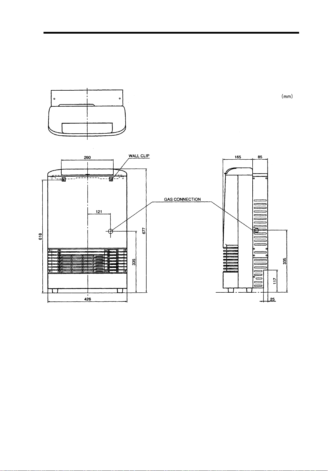
2. Dimensions
Note: All dimensions are in millimetres
-
-
-
Page 8
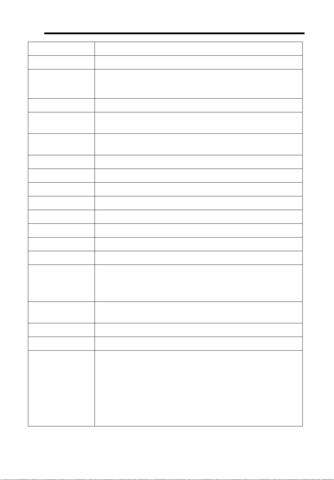
3. Specification
Type of applia nce Fan forced flued g as s pace heater
Model RHFE-308FTR
Dimensions Width - 425 mm
Depth - 165 mm (with back spacer 250 mm)
Height - 677 mm
Weight Approx 17 kg
Connections Electrical - AC 240 V 50 Hz / 60 Hz
Gas - R½ 15 BSP male threa
Electrical
High: 39 W Low: 30 W
Consumption
Output 10.5 MJ/h
Combustion system Stainless steel bunsen burne
Ignition system Continuous electrical spark, direct to main burner
Operati on Fi ng e r touch cont rol buttons
Temperature control Electronic thermostat, modulating HI-LOW/OFF
Temperature range LOW (10
o
C), 16 ~ 26oC (1oC incre ment s), HIG H (co ntin uous)
Warm air outlet Bottom of appliance
Air volume control HI ~ LOW (automatic)/OFF
Timer operation Dual Timer - 24 hour, ON & OFF Timer
Operation - 24 hour
Clock - 24 hour digital display
Temperature control - 26
o
C limit when using timer program
Indicator Burner ON, child lock, filter, economy, digital display, over-ride, clock
setting, timer setting, timer, temperature display
Operating buttons ON-OFF, up-down, child lock, economy, timer, clock setting, over-ride.
Humidifier tray Capacity - 0.8 Litres
Safety devices Flame failure - flame rod
Over heat - bi-metal switch (130
o
C, 90oC)
- thermal fuse (216oC)
- thermistor (130~90oC)
Power failure - PCB
Power surge - 3 Amp fuse
Fan delay - micro computer timer (Max 210 secs
Pre-purge - combustion fan, pre-purge timer, spark sensor
Room over heat - automatic cut off at 40
-
-
-
o
C after 10 mins
i
i
Page 9
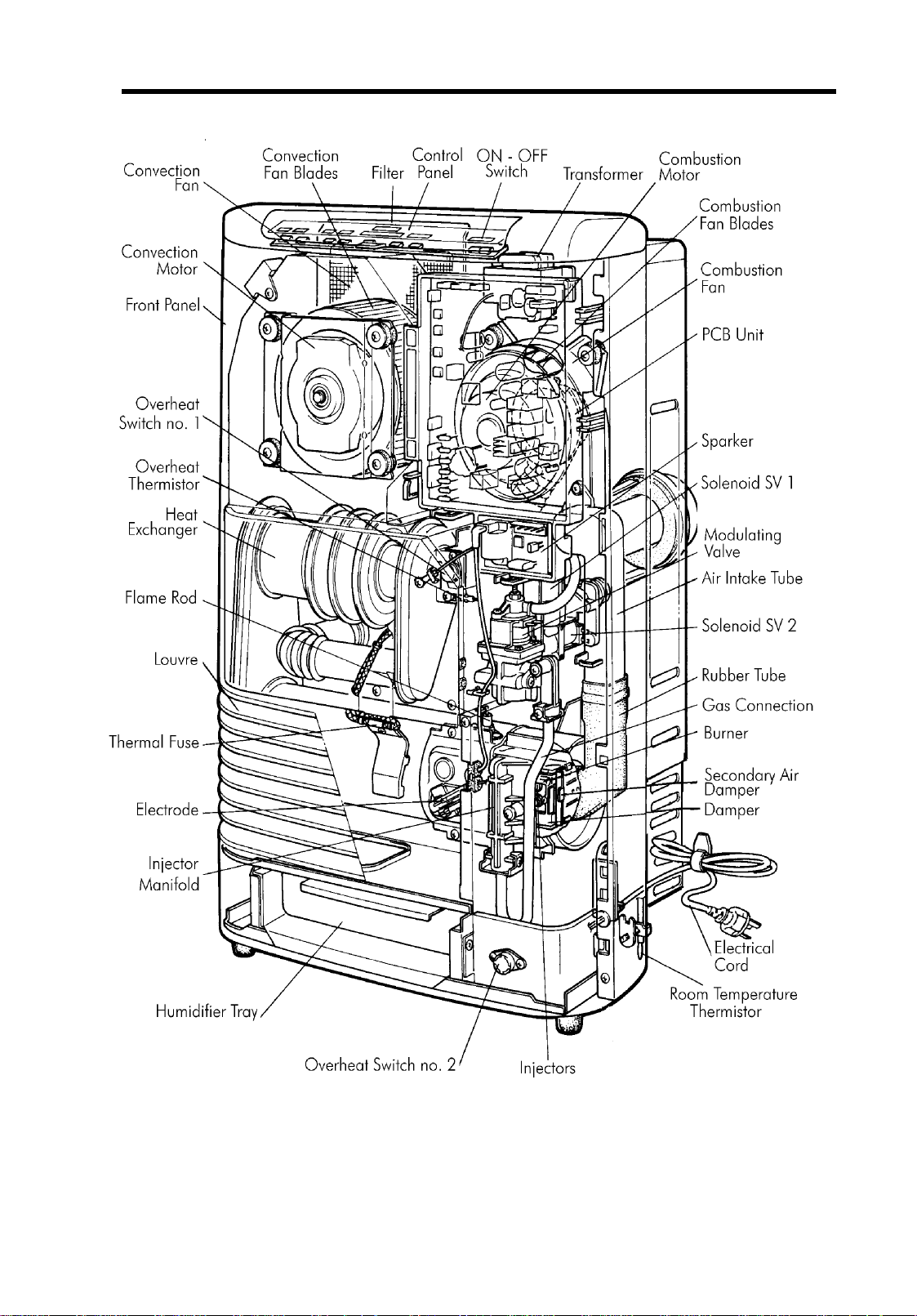
4. Cut-Away Diagram
-
-
-
Page 10
5. Installation
NOTE:
refer to the installation instru ctions in the custome r’s operating instructions.
The informa tion provided he re is on ly a guide. F or full det ails on installa tion proc edures, please
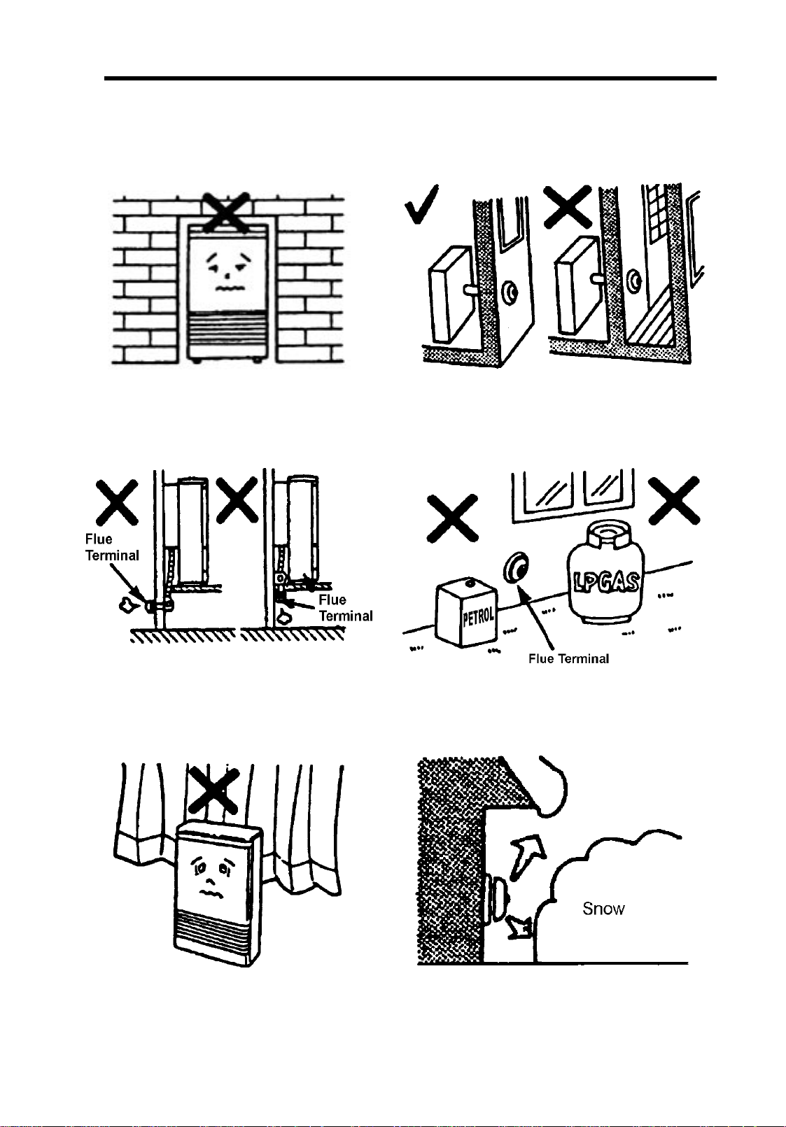
This heater is not designed to be built in. The flue may be positioned directly under opening
windows, with a minimum clearance of 150 mm.
The flue is not designed to be positioned unde
floors or below the level of the heater.
Flue fittings must be kept clear of flammabl
materials.
The flue terminal should be positioned away from
flammable materials.
In areas subject to heavy snowfall, keep snow
clear of flue termin al at all times.
-
-
-
i
i
Page 11
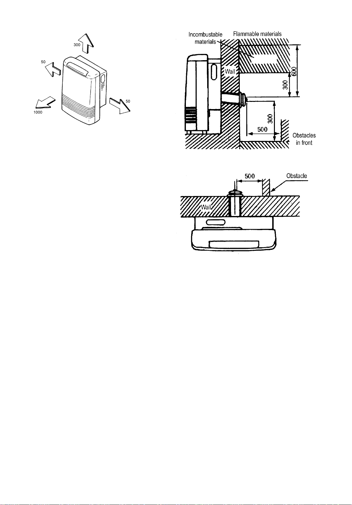
Recomme nded mi nimu m cle ara nce s an d dist anc es from obs truc tions.
-
-
-
i
i
Page 12

6. Performance Characteristics
1. Basic Combustion Specification
Item Specification
Rinnai model number RHFE-308 FTR
Gas typ NG Propane/LPG
Gas consumption MJ/h
Injector size (∅ mm) 1.30 0.90
Injector quantity 2 2
Regulator pressure (kPa)
Burner marking P P
Combustion method Bunsen burner
Burner type Stainless slit style
Solenoid valve Direct s i n g le seated valve type
Modulating solenoid valve Direct single seated valve type
HI
LO
HI
LO
13 13
55
0.60 1.04
0.12 0.19
2. Combustion Fan Speeds (rpm)
Natural Propane/LPG
Ignition 1710 1560
Re-ignition 1800 1680
Normal - High 3000 3090
Normal - Low 1440 1440
-
-
-
i
i
Page 13
3. Warm Ai r Discha rge Temperature Di stribution
Condition: < High Combustion >
Test gas: Natural
Measured input: 12.55 MJ/h
Nominal input: 13 MJ/h
Room temperature: 25oC
(Unit
24 24 55 9
45 72 64 18
56 81 83 36
62 66 77 42
68 43 70 45
42 39 57 45
Condition: < Low Combustion >
o
∆
C)
Test gas: Natural
Measured input: 5.27 MJ/h
Nominal input: 5 MJ/h
Room temperature: 25oC
10 17 30 9
23 39 38 13
29 48 42 28
35 44 46 37
37 28 43 34
22 26 31 28
4. Measurement Points
(Unit
o
∆
C)
-
-
-
i
i
Page 14

5. Warm Air Discharge Velocity
Convection Fan rpm HIGH: 740
LOW: 550
Room Temperature: 22oC
(Unit: m/sec)
1.62
1.46
1.99
1.78
3.20
2.61
3.35
2.66
3.27
2.47
3.13
2.37
2.57
1.32
2.57
1.92
3.54
2.53
3.44
2.60
3.37
2.52
2.11
1.23
1.70
1.34
2.89
2.15
3.12
2.44
3.14
2.28
3.33
2.62
3.33
2.54
Air Flow: Average air velocity on High: 2.784 m/sec
Average air velocity on Low: 2.10 m/sec
Air flow rate on High: 3.82 m3/min
Air flow rate on Low: 2.89 m3/min
Air flow outlet area: 0.0229 m
2
6. Noise Level
1.08
0.84
2.12
1.58
2.51
1.91
2.75
2.08
3.32
2.46
3.42
2.58
Unit: dB(A).
High 36.5
Low 31.5
7. Th ermal Eff iciency
Conditions: Horizontal mushroom flue with unit installed with back spacers.
Gas Type Combustion Thermal Efficiency (%)
Natural
High 81.3
Low 84.8
High 83.5
Propane
Low 88.1
8. Humidifier Capacity
Method Tray Capacity Evaporation
Evaporation 0.8 Litres 0.1 Litres/hour
Note: Evaporation rate varies depending on conditions of use.
Conditions: Standard setting: High combustion
Measurement Method: According to JIS (Japanese Industrial Standard)
-
-
-
i
i
Page 15
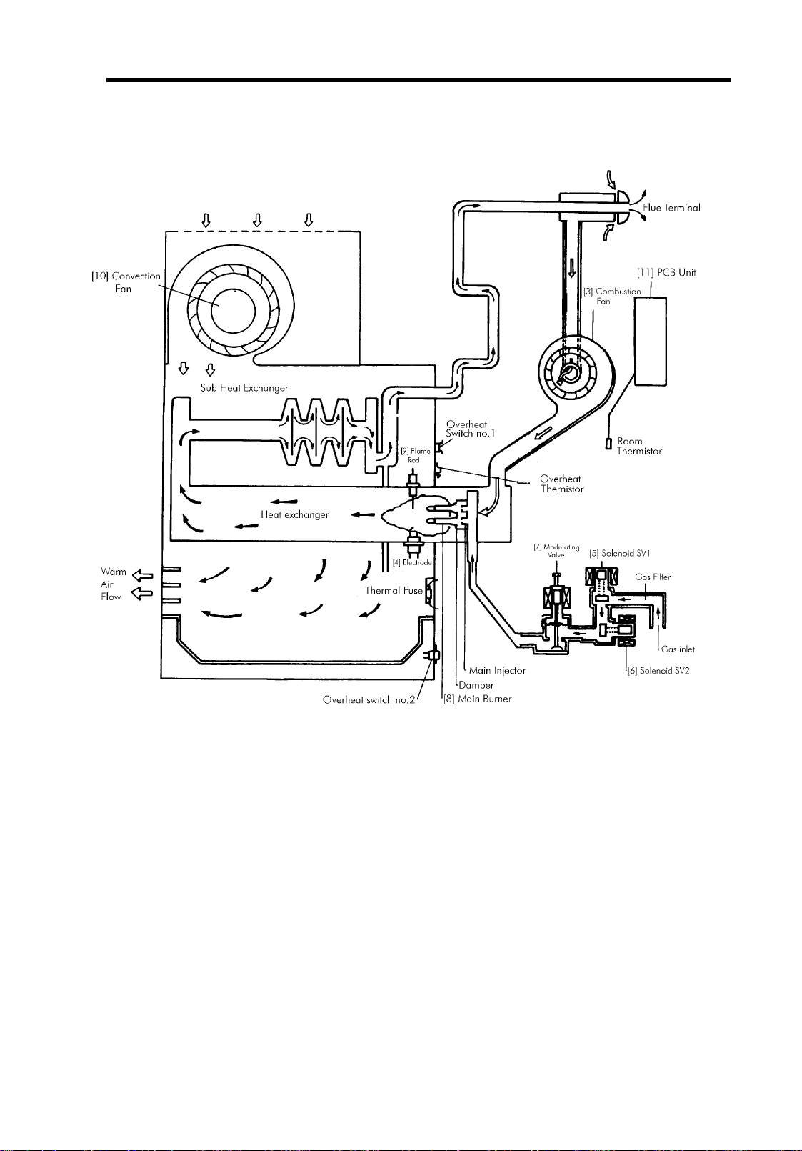
7. Schematic Diagram
-
-
-
i
i
Page 16
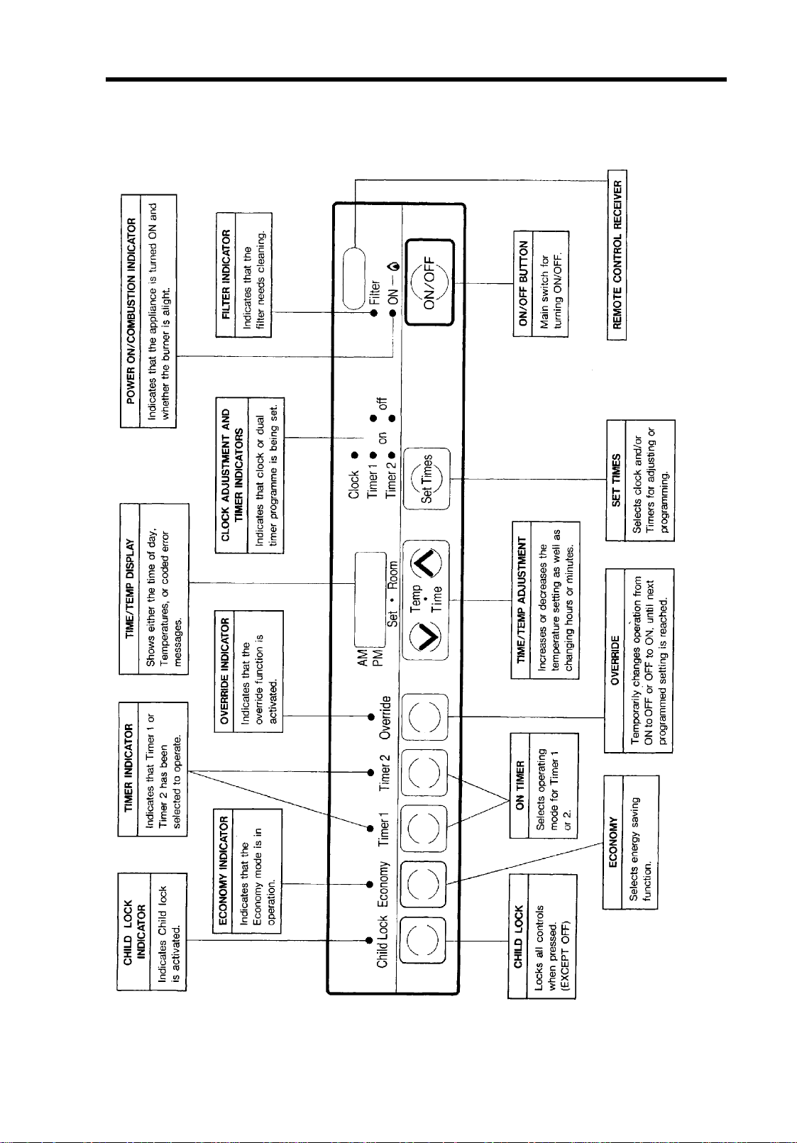
8. Control Panel Layout
* Refer to “Appendix” on page 59 for explanation on setting clock and programming timers.
-
-
-
i
i
Page 17

9. Operating Principles
1. Normal Operation
Push the ON/O FF Button to operate the a ppliance. T h e Po wer ON/Combustio n Ind i c a t or will glow green.
The comb ust ion fan will run o n high until p re-purge is completed.
Pre-purge is completed after approximately 15 seconds, following which, the c ombustion fan will decrease
revolutions to enable ignition to occur. After the combustion fan reaches a pre-determined speed,
(depend ing on gas type) the electrode pr od u c e s the sp a r k to begin t he i gnition cycle.
After the spark i s sen sed as having crosse d the spark gap by t he PCB, the solenoids (SV
as the modulati ng valve will open and allow ga s to flow to the burner.
The flame rod senses the flame on the main burner. After the flame is sensed, the Power ON/Combustion
Indica tor chang es to red and the spark stops. After an additional 15 secon ds the convect ion fan begins to
operate.
The room temperature is se nsed by the temperature thermistor located at the rear of the appliance. The
printed c ircuit b oard cont rols th e air/gas ratio to the optimu m level according t o the select ed temperature.
The combustion fan is adjusted in conjunction with the opening degree of the modulating valve. The
convection fan is adjusted in the same manner.
& SV2) as well
1
2. Thermostat Control
The selected and room tem peratures are display ed on th e Time/Temp Display. T ime and temperature are
displayed alternately depending whether the heater is running or not. The selected temperature is altered by
pressing the Time/Temperature Adjustment buttons.
3. Turnin g Off
Simply press the ON/OFF Button. The solenoids, together with the modulating valve will close. The
combus tion f an will also sto p, and all indi cat ors will go out. After the burner ex t i n gu is h es, the convection
fan will c ontinue to run for up to 210 seconds, ensur in g the appliance is cool.
4. Economy Mode
To enga ge t he economy funct io n press the Economy b u tt on while the heater is operational. The Economy
Indicator will glow. Once the selected temperature has been reached, the economy function is designed to
drop this temperature by a total of 2oC over a period of one hour. Aft er 3 0 min u te s t he tem p eratu re will be
reduced by 1oC. After a further 30 minutes the temperature will be reduced by another 1oC. This does not
result in a loss to th e heatin g effect ivene ss , and is an e nergy s avi ng feat ure. Y ou may press the Economy
button again at any time, to cancel the economy function.
5. Child Lock
To act iv ate th e chi ld lock press the Child Lock b ut t on. The Lock Indic a tor will glow.
If the child lock is activated during normal operation, then no functions other than the ON/OFF Button will
be operable until the lock is released.
If the child loc k is activated whi lst the appliance is OFF, then the complete range of functions will be
locked.
-
-
-
i
i
Page 18
6. Fi lter Indicator
When the air filter becomes covered in dust and the temperature inside the appliance rises, the Filter
Indicator will glow.
7. Fu zzy Logic
a. The Purpose of Auto Comfort [Fuzzy Logic]
The main aim of the Auto Comfort function is to heat a room by controlling the flow of the warm air coming
from the heater. This increases heating efficiency as well as improving control over the flow of warm air
being disch ar ged by th e app liance.
In order to achie ve comfortable heating, it is preferable to avoid cold d ra fts o r draughts from the appliance.
Also, for incre as ed efficien c y i t is import ant to redu ce ove r h e ati ng i n the room an d concen trate heating in
the area where people are most oft en situated.
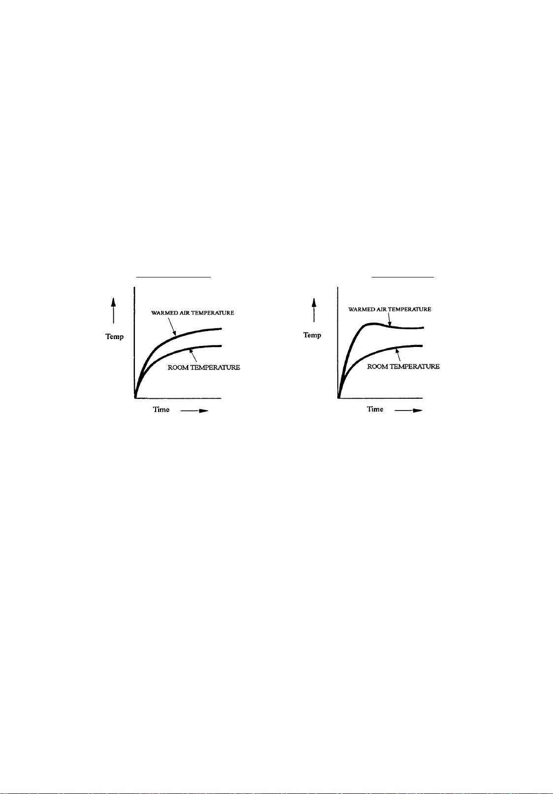
Fuzzy Logic is us ed i n order to ac h ie ve the followi ng impro ve d h eati ng pattern.
Standard Control
'Room temper ature' and 'the time elapsed since the start of combustion’ are the basis for fuzzy logic. Th
means of contro l is t he s pe ed of the convection fan and modulation of gas combustion.
Fuzzy Co ntrol
b. Fuzzy Logic Summarised
In the case of a conventional fan heater, the convection fan operates normally from the time of ignition, and
a cold draught may accompa ny the flow of air from the appliance. To solve thi s problem, fuzzy logic
controls the speed of the convection fan after taking into consideration the room t emperature at the time of
ignition. For example, in the case of t he room temperature being low, the fan is made to rotate at a low
speed, raising the dis charge air temper ature. As the room temperature rises, the speed of the convection
fan is g radua lly incre as ed. In this way i t is possible to e nsure a comforta ble volume of warmed a ir whilst
decreas ing the possibility o f cold draughts immedi ate ly after ignition.
The fan s p eed incre as es proportiona l ly as time passes and the room gradu a lly he a t s u p. This improves the
warm air distribution, assisting in a reduction of stratification throughout the room and resulting in more
effective heating conditions. The PCB then continually monitors the room temperature, and adjusts the fan
speed according t o t he conditions at the time.
8. Clock and Timer Setting and Operation
Refer to “Appendix” on pa ge59 of this manual.
9. Intelli gent Timer [Pre Heat]
This func tion en a bl e s th e room to be heate d t o the pr e- se t temper a tur e pr ior t o the time pro grammed in the
On Timer. See Intelligent Timer [Pre-heat]” on pa ge14 for more information.
-
-
-
i
i
Page 19
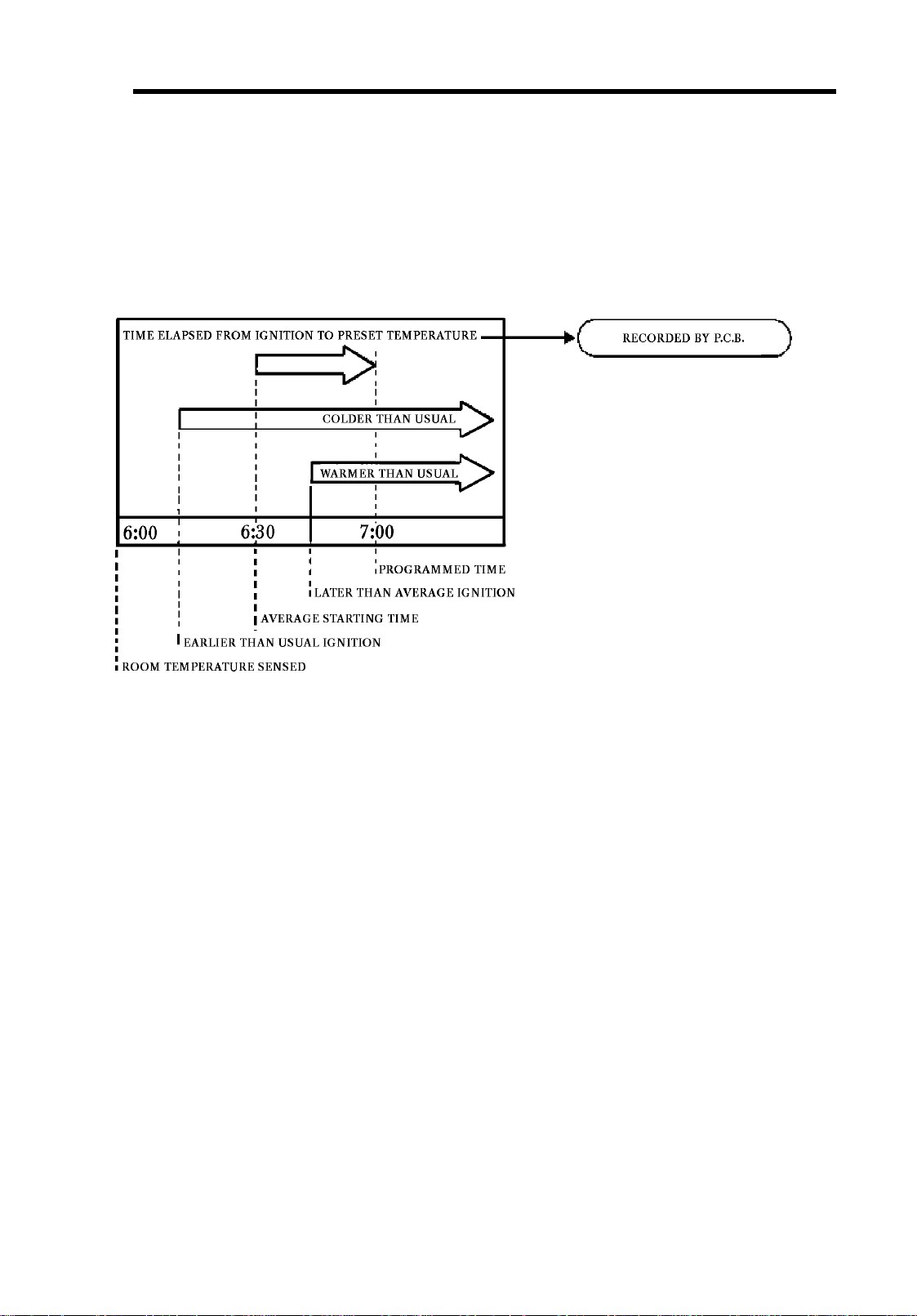
10. Intelligent Timer [Pre-heat]
The Intelligent 2-way 24-hour programmed dual digital Timer [Pre-Heat] function operates in
conjunction with either “On-Timer”. It enables the pre-set temperature to be reached by the time
programmed by starting ignition up to an hour before the time programmed to start heating.
The actual ignition time is calculated using the difference between the room temperature and set
temperature and the warming-up time which elapsed the last time the appliance was used. The
maximum time ignition will precede the pre-set time is 1 hour. The following chart illustrates how
the intelligent timer operates.
The two timers can be programmed and used individually, or sequentially. Timer operation, once
set, will remain on stand-by for the next day after the final OFF sequence, unless ON/OFF switch is
pressed.
-
-
-
Page 20

11. Safety Devices
Flame rod sensor
Senses main burner ignition an d s huts off the solenoid v al ves when the flame cu r r ent drops below 0.1 µA.
Spark sensing circuit
Senses the location of spark a nd opens the solenoid v alve s only whe n the spark locat ion is confirmed as
correct.
Pre-purge circuit
Purges heat exchanger and flue prior to spark commencing.
Combustion fan rpm s ensing circuit
Senses the operation of the combustion fan and maintains a pre-determined rotation speed.
Overheat protecti on switches
Shuts of f th e so len o i d valves and cut off gas supply in the case of over heating.
i) Bimetal OHS1
Operates at 130 ± 5°C
Recovery at 115 ± 7°C
ii) Bimetal OHS2
Operates at 90 ± 5°C
Recovery at 75 ± 7°C
iii) Thermal Fuse
Cuts o u t at 21 6 ± 2°C (one shot)
iv) Thermistor
Operates at 130 ~ 90
o
C (High ~ Low).
Fan delay
The convection fan starts after a short delay to avoid cold draughts, and keeps running after burner
extinction to allow the uni t to cool down.
ON AT 15 sec, after ignition commences
OFF AT max. 210 sec, after combustion
Power failure circuit
Shuts off the solenoid valves if a power p ower failure occurs. The unit will relight afte r the power is
restored , and t he c lo c k t i m e will be slow by the amount of tim e the p o we r was off.
Thermistor Type Temperature Control
Controls r oom temperatur e wit h i n the ran ge of 16~26oC in 1oC steps.
-
-
-
i
i
Page 21

10.Overheat Control Method
The overheat thermistor activates the overheat sensor and the filter indicator, as well as increasing the fan
rpm.
(A) Overheat Sensor
The overh ea t thermistor act iv ates at different temperatures for dif f eren t g as r ates ( c omb ustion).
(B) Filter Indicator
Note 1: Once the over h eat li mit t emp eratur e has been se nsed and the f ilter in dic ato r be gins f lash ing, it
will not go o ut , even if th e temperature falls b elow t he limit.
Note 2: Once the filter indicator begins flashing, gas input is limited to roughly 88% of high combustion.
-
-
-
i
i
Page 22

(C) Convection Fan RPM Increas
The fan rpm increas es t o compen sa te for a redu ction in a ir flow due to a clogged air filt er or other causes.
The convection fan rpm is normally determined by combustion level. The speed increases by
approxim at e ly 100 rpm at High.
-
-
-
i
i
Page 23

12. Operation Flow Char t
p
ON/Comb
O.H
R
C
)
)
)
)
(
)
(
(
ON/Comb
1
Turn ON/OFF switch ON
A
i
Room temp. displayed
2
3
4
6
Combustion Fan HI ON
Connect power cord
ower ON
and turn
EProm trans-
mission Normal
Yes
ustion
i
SV circuit
Normal
Yes
OHS & TF
Normal
Yes
Thermistor
Yes
oom
Temp.Thermistor
Yes
Flame rod
current below
A
0.1
Yes
No
a
No
No
After 2 Sec from a
No
(After 2 Sec from a)
No
(After 20 Sec from a)
No
Problem eliminated
73
ON/Combustion
71
ON/Combustion
indicator flashes red
14
Filter indicator flashes
ON/Combustion
indicator flashes red
33 (open circuit
34 (short circuit
ON/Combustion
indicator flashes red
33 (open circuit
34 (short circuit
ON/Combustion
indicator flashes red
72
ON/Combustion
indicator flashes red
Problem eliminated
All indicators OFF
Turn ON/OFF
switch OFF
Combustion
15
Fan >1710
Combustion Fan LOW
Flame rod
current below
6
Combustion
9
fan > ignition +
Sparker activates
10
Spark sensing
Solenoid SV1 Opens
11
Solenoid SV2 Opens
12
Mod. Valve half opens
Flame sensed
6
above >1
ON/Combustion
indicator flashes red
Sparker OFF
Combust'n fan (med) ON
0.1A
60 rpm
Normal
(After 15 Sec)
No
rpm
Yes
Yes
Yes
No
No
No
(After 10 Sec)
After 20 Sec)
(After 30 Sec)
After 2 Sec)
Combustion Fan OFF
Combustion Fan OFF
Combustion Fan OFF
Combustion Fan OFF
Sparker OFF
Yes
61
ON/Combustion
indicator flashes red
72
ON/Combustion
indicator flashes red
61
ON/Combustion
indicator flashes red
53
ustion
indicator flashes red
b
Solenoids SV1, 2 close
No
No
c
A
Yes
15 sec after b
Yes
Spark sensor
Normal
Yes
Solenoids SV1, 2 close
No
(After 1 sec)
11
ON/Combustion
indicator flashes red
53
ON/Combustion
-
-
-
Page 24

C
(POV) C
O
O
(
)
p.
(
)
(
)
(
)
N
Modulating Valve HI
g
(
)
g
No.
30
C
No.
90C
Combustion Fan HI
Convection Fan HI
Temp. control begins
Convection Fan ON
14
4
OH Thermistor
Temp. normal
Filter indicator
flashes red
Room temp.
within 2C of
set tem
Modulating Control
POV
Modulating Control
Combustion Fan
Modulating Control
Convection Fan
Safety Devices
Operate
Less than 255 sec
o
Yes
12
ON/Combustion
Power reinstated
Operation stops
Power failure
Less than
5 times
Combustion
rate < medium
90 secs>ignition
Flame Senser
Device Operates
Convection Fan
FF
Convection Fan
MED OFF
Combustion Fan
FF
Solenoid Valve
Modulating Valve
losed
> 90 Sec
from c
Room temp >
Set temp by over
4
4
1C
Temperature Control OFF
Solenoids SV1, 2 OFF
Modulating Valve Closed
Combustion Fan OFF
ON/Combustion
indictor
Convection Fan
MED ON
Convection Fan OFF
Room temp
> Set temp
reen
Room temp.>40C
4
for over 10 mins
ON/Combustion
indicator flashes red
d
Less than 60 sec
4
16
Room >Set temp
within 2C
16
2
Yes
O.H. Thermistor
Overheat Switch
Overheat Switch
Thermal Fuse melts
ON/Combustion
indicator flashes red
within ran
1 > 1
2 >
14
Filter indicator
flashes red
e
ON/OFF SW failure
1
ON/Combustion
indicator flashes red
Combustion Motor
rpm abnormal
70
61
ON/Combustion
10 mins after d
-
-
-
Page 25

OFF
(
)
ECONOMY
TIMER OPERATION
ON/OFF Switch OFF
Temperature
Control ON
Yes
Solenoids SV1,2 OFF
Modulating Valve OFF
Combustion Fan OFF
Convection Fan MED
Operation/Combustion
Indicator OFF
Change from Room
& Set Temp to clock
All Indicators OFF
Convection Fan
No
Less than 255 sec
Economy Switch ON
Economy Indicator ON
Room Temperature
drops max. 2C
Economy Switch OFF
Economy Indicator OFF
Temperature Control
Operates
ON/OFF Switch ON
Timer Switch ON
Timer Indicator ON
Pre-Heat set
up Time
Yes
Timer indicator flashes
Normal operation start
Set-up Time
Yes
Normal Operation Stops
No
No
-
-
-
Page 26

13. Diagnostic Points
* “Flow” denotes references on the “Operation Flow Chart” on page 18.
* “CN” denotes connector number on the “Wiring Diagram” on page 22.
Flow CN Component Wire Colour Value (Normal)
1 I ON-OFF Switch red - blue
blue - blue
H Overheat Circuit white - black
H1 Overheat SW 1 white - red
H2 Overheat S W 2 red - black
2
H3 Thermal Fuse white - white
3 A Overheat
Thermistor
4 A Room Temp.
Thermistor
6 E1 Flame Rod yellow-yellow < DC 0.1 µA
7 G Combustion Fan red -black
9 G Combustion Fan
white - white
temperature
yellow-yell ow
temperature
white - black DC 1 ~ 4 V; > 3420 pulse/min (> 57 Hz
black - whi te below ignitio n revolution + 120 rpm
initial ignition LP: 3480, NG: 3600 pulse/min
0.6 ~ 523 k
20°C: 78 k
1.8 ~ 844 k
DC 3 ~ 10 V, resistance 1
(current flows when switched on)
Less than DC 1 V; < 4
< DC 1 V
(current flows)
< 1
Ω
( < 0.6 kΩ: short, >523 kΩ: open
Ω
, 100°C: 3.6 kΩ, 150°C: 1.1 k
Ω
( < 1.8 kΩ: short, >844 kΩ: open
Ω
0°C: 123 k
, 20°C: 39 kΩ, 40°C: 14 k
Ω
DC 7 ~ 40 V; > 10 M
Ω
Ω
(current flows)
Ω
Ω
Ω
re-ignition LP: 3720, NG: 3780 pulse/min
10 F Sparker blue-red AC 85 ~ 110 V
11 F Solenoids 1 & 2 black - yellow
12 H Modulating Valv grey - grey
Over-heat
14 A
15 G
16 A
17 D Convection Fan grey - pink
Thermistor
Combustion
Fan
Over-heat
Thermistor
white - white
(filter
indicator
white - black
(normal rpm)
white - white
(OHS on)
high
low
high LP: 5760, NG: 5700 pulse/min
low LP: 3000, NG: 3240 pulse/min
high
low
DC 78 ~ 100 V, 1.3 ~ 2.2 k
DC 1 ~ 15 V (low ~ high) 8 0 ~ 100
flashes below 50 Hz; 2.2 k
flashes below 8.6 k
operates belo 1.7 k
operates below 5.3 k
AC 50 ~ 108 V (low ~ high ) , 9 0 ~ 180
Transformer Values
Wiring Diagram Australia [240 V] New Zealand [230 V]
Yellow - Blue
AC 130 ~ 180 V; 200 ~ 400
Ω
AC 130 ~ 180 V; 200 ~ 400
Ω
Ω
Ω
Ω
Ω
Ω
Ω
Ω
E
B Grey - Grey AC 216 ~ 264 AC 207 ~ 253 V
Blue - Black
Red - Red
-
AC 10 ~ 16 V; 1 ~ 3
AC 25 ~ 50 V; 1 ~ 3
-
Ω
Ω
-
AC 10 ~ 16 V; 1 ~ 3
AC 25 ~ 50 V; 1 ~ 3
Ω
Ω
i
i
Page 27

14. Wiring Diagram
-
-
-
Page 28

15. Block Diagram
-
-
-
Page 29

16. Time Charts
-
-
-
Page 30

-
-
-
Page 31

-
-
-
Page 32

17. E2 PROM
Memory Function for Error History, Estimated Combustion Time, and Estimated Number of Operations
E2 PROM (Electrically Eraseable and Programmable Read Only Memory) is a ROM in which data
is electronically programmed or erased. Programmed data will be stored semi-permanently even if
the power fails or is disconnected.
The most recent data on the past nine errors, estimated combustion time and estimated number of
operations are included in the information stored in E
2
PROM.
• How to Read the Data
Confirm the unit is off, press “/\”, “\/” and “Economy” buttons at the same time for at
least 2.5 seconds (a beep will be heard once). The data will be displayed on the LED display in the following order: Error Messages, Estimated Combustion Time, Estimated
Number of Operations.
• Data Display
The most recent error message (No. 1) will be displayed first, then it will be followed by
up to eight previous errors (No. 2~9) displayed for 2 seconds each, as shown below. Following this, Estimated Combustion Time and Estimated Number of Operations data will
be displayed for 4 seconds each as in the example below (No error messages “-- . --” will
be displayed if no errors were recorded).
Estimated Combustion Time will be displayed as below if between 0 ~ 9,999 hours. However, if it
is more than 10,000 hours, then “H” is added to the beginning of the display. Hours will be rounded
up to the nearest 100 as shown below.
9999 hours 10000~10099 hours 10100~10199 hours
Estimated Number of Operations will be displayed as below (1=10 times) if between 10 ~ 99,999
times. However, if it is more than 100,000 times, then “H” is added to the beginning of the display.
Operations will be rounded up to the nearest 1000.
99990~99999 times 100000~100999 times 101000~101999 times
*
Note:
Estimated Number of Operations is the number of ON-OFF movements on the solenoid
valve.
-
-
-
Page 33

• Deleting Data from E2 PROM
Confirm the unit is turned off, and press “/\”, “\/”, “Economy” and “Lock” buttons at
the same time for at least 1 second. (Lock beep will be heard once and another beep wil
be heard a second later).
Digital display turns off and displays “- - : - -” when the data is deleted completely. However, the data on Estimated Combustion Time and Estimated Number of Operations
cannot be deleted.
Once recorded in E2 PROM, the data is protected from power failures.
Permanent Data Deletable Data** (initial settings)
• Modulating Valve Supplement
Current Value (HIGH)
• Modulating Valve Supplement
Current Value (LOW)
• Convection Fan Supplement
Current Value (HIGH)
• Convection Fan Supplement
Current Value (LOW)
• Estimated Combustion Time
• Estimated Number of Operations
This data can be deleted as described above.
**
• Error History (none)
• Clock (12:00 am)
• Economy Operation (OFF)
•Lock (OFF)
• Preset Room Temperature (22oC)
• ON Timer (06:00 am)
-
-
-
Page 34

18. Error Coded Messages
Error is displayed as a number on clock flashing. (Filter indicator will also flash in the case of overheat.)
Error Code Probable Cause Comments Ref †
--:--
11
12
14
16
31
32
33
34
Power failure When power failure is sensed operation
stops.
Miss ignition Flame current does not reach 0.1µA within
the given time, after solenoid valve opens.
Flame failure Flame rod current remains below 0.1 µA for
3 seconds during initial combustion.
Over heat safety
device
Over temperature
cut off
Room temperature
thermistor
disconnection
Room temperature
thermistor short circuit
High-limit thermistor
disconnection
High-limit thermistor
short circuit
High-limit temperature thermistor or
thermal fuse has activated.
Room temperature is sensed as being above
o
C for longer than 10 minutes.
40
Room temperature thermistor open circuit 4
Room temperature thermistor wire trapped,
touching bare metal
High limit thermistor open circuit for over 2
seconds
High limit thermistor short for over 2
seconds
-
6
6
2
4
4
3
3
Sparker not OFF within 20 seconds at time
of ignition
53
61
70
71
72
73
† Refers to the number on the operational flow chart, page 18, and diagnostic points, page 21.
Abnormal spark
sensed
Abnormal combustion
fan motor rpm
ON/OFF switch
failure
Solenoid valve check Solenoid valve(s) (SV1, SV2) signal and
Flame rod failure Flame rod current should not go below
Communication
failure
1st spark sensed not within 2 seconds
2nd spark sensed spark not continuous for 1
second after solenoid valve opens
Speed is not achieved within time or goes
over speed level
ON/OFF switch on continuously for more
than 15 seconds
response signal are different.
0.1µA within 20 seconds of starting.
2
Data transfer between CPU and E
fails.
PROM
-
15
1
11
6
-
* To reset error codes, press the ON switch while the error code is showing. This will not reset error codes “71"
and “73"; power needs to be reset to erase these codes.
-
-
-
Page 35

19. Fault Finding
Main Faults and their Remedies
* Numbers on the right hand side of this table refer to “Causes of Faults and Suggested Remedies” on pa ge31.
Fault Sym ptom Error Codes Check Points / Remedy
The Economy
indicator will not
come ON.
After having
pressed the ON OFF switch the
appliance will not
operate.
Insufficient he a ting. * Check s el ected roo m temperatur e setting
Burner goes out
during operation.
11
12
14
16
* Confirm t ha t Economy M o de has been selected
* Confirm e l ectr ical co rd is s ecur el y in to the power point
* Check ga s s upply
* Confirm no gas escapes
* Check for air in the gas supply
* Reconfir m ga s t yp e specified
* Check for blocked air filter
* Check fo r an obstructi o n i n the warm air flow
* Reconfir m ga s pressure at appliance
* Ensure flue terminal is not blocked
* Ensur e air filter is not b lo cked
* Power Failure
* Check fo r an obstructi o n i n the warm air flow
* Reconfirm gas type specified
* Confirm no gas escapes
* Check for flash back
* Check for high room temperature
* Reconfirm electrical supply at power point
. . . . . . . . . . . . . . . . . . . . . . . . . . . 1
. . . . . . . . . . . . . . . . . . . . . . 1
. . . . . . . . . . . . . . . . 1
. . . . . . . . . . . . . . . . . 1
. . . . . . . . . . . . . . . . . . . 3
. . . . . . . . . . . . 1
. . . . . . . . . . . . . 5
. . . . . . . . . . . . . . . . 3
. . . . . . . . . . . . . . . . . . . . . . . . . . . . . 8
. . . . . . . . . . . . . . . . . . . . . . 1
. . . . . . . . . . . . . . . . . . . . . . . . 6
. . . . . . . . . . . . . . 7
. . . . . . . . 2
. . . . 4
. . . . 4
. . . . . . 8
Gas odour. * Confirm no gas escapes (at connection)
* Product of combustion leak
Power failure.
† Error is displayed as roo m tempe ratu r e LEDs flashing
-
--:--
* Power failure ( > 0.2 seconds
. . . . . . . . . 1
. . . . . . . . . . . . . . . . . . . 9
. . . . . . . . . . . . . . . . 8
-
-
i
i
Page 36

Causes of Faults and Suggested Remedies
1. Gas supply
In cases of miss ignition, insufficient heating and gas
smell, ch eck that:
• The gas supply pressure is correct.
• The specified gas type is correct for the area.
• There are no breaks/escapes in gas supply.
• There is no air in the gas supply .
⇒
Check the gas pressure at both the meter and the
appliance.
⇒
Air in the gas line will prevent the appliance from
igniting.
2. Thermostat sett ing
When the room does not reach the selected temperature, or
the appliance will not remain alight, check that:
• The selected temperature is not set lower than the
room temperature.
⇒
Select the required temperature setting with the UP/
DOWN se l ec tion buttons.
3. Blocked air filter
If insufficient hea ting or l ockout occurs, ch eck that:
• The air filter is not blocked with dust.
⇒
If the air filter is blocked, the safety device will operate.
..... 14 flashing
⇒
The filter must be cleaned at least once pe r month.
4. Air flow obstruction
If insufficient hea ting or l ockout occur red, check that:
• There are no obstacles in front of the appliance or
louvres.
..... 14 flashing
⇒
There should be no articles within one (1) metre of the
front of the appliance.
5. Flue termi nal
If flame failure occurs during normal operation, check
that:
• The flue terminal on the exterior wall is not
obstructed in any way.
..... 12 flashing
⇒
Check in particu lar for shrubs growing over the flue
terminal or a thick build up of spider webs.
6. Flash back protection
If flame failure occurs during normal operation, check:
• The flue terminal air intake is not blocked.
• For dust or foreign material on the burner.
• Combustion specification and gas type.
..... 12 flashing
7. Room temperature
• Is the room temperature unusually high?
⇒
10 minutes after having sensed 40°C the appliance will
automatically go out.
..... 16 flashing
8. Power failure
• If there has been a power failure for 0.2 seconds
or longer. Current time will be displayed on display when “set times” button is pressed once.
(Time will be slow by duration of power failure).
..... -- :-- flashing
9. Smell of products of combustion
If there is a smell of gas or products of combustion, check
that:
• The flue manifold behind appliance has not come
undone.
⇒
The pro duc ts of co mb ustio n a re leav ing t h e a ppliance
through the flue terminal.
-
-
-
i
i
Page 37

Before conta cting Rinna i, please c h eck the following p oi nt s . T hese p oints are part of the nor ma l ope ration of the unit.
At Ignition
Is the heater plugged in? Is there a power failure?
Have the fuse or breaker blown at the switchboard?
Heater does not o pera t e.
Warm air does not flow when the burner lights. The fan is started automatically after a short delay.
Are the air filter, flue, or warm air outlet blocked?
Are Timers set? Clear Timers and operate again.
Is the central timer on? (where fitted)
This is to allow the heat exchanger to warm up.
Smoke or strange smells are produced on the first trial
light u p after in stallation.
Sharp clickin g noises at ign it ion , o r wh en the unit cuts
down on the thermostat, or goes out.
This is caused by grease or oil and dust on the heat
exchanger a nd will s top af te r a short time.
This is simply expansion noise from the heat exchanger.
During Combustion
Clunking noise when the therm ostat operates. This is the sound of th e solenoid gas valves.
Is the air filter or warm air outlet blocked?
Unit is not heating room?
Air filter or louvres are blocked or obstructed. Allow heater to cool, clean air filter, ope rate again.
Heater will not reignite after overheating. Heater does not reignite. Repair is necessary.
Is the set temperature high enough?
Are the doors and windows of the room closed?
When the Unit is Turned Off
Convection fan cont inues to r un after tu rning off. This is to remove the residual heat f ro m the heat exchanger,
the fan will stop when the heater cools down.
Other Points
Steam is discha rged from the flue terminal. High efficiency appliances tend to discha rge water vapo ur
on cold days, this is normal.
Check is central timer is switched off (where fitted), or
Unit cuts off without apparent reason.
Power failure.
Remote control does not operate. Check battery. Try moving closer to the heater.
-
-
whether filters are blocked, (dirty filters will cause the
heater to overheat).
When power is restored, the appliance will begin to heat if it
was on at the time of power failure. Clock will be delayed by
the length of the power failure.
-
i
i
Page 38

20. Fault Analysis
After having operated the appliance and:
A.
i) The combustion fan doesn’t begin to rotate, or suddenly stops after running for a short time.
ii) There is no spark (after 30 seconds).
iii) The solenoids do not open, preventing gas flow to the burners.
iv) The convection fan does not begin to rotate, approximately 15 seconds after ignition.
Is there electrical supply NO 1. Confirm the connection at the wall socket
2. Is the 3 amp fuse blown?
YES
a. The appliance does not operate.
i) Open circuit or loose pin connector on PCB or wiring loom.
ii) ON/OFF button faulty. ...
iii) Faulty Printed Circuit Board.
iv) Control panel PCB faulty.
v) OHS is ‘OPEN’. (‘CLOSED’ Normal) ...
vi) Thermal fuse has melted.
vii) Solenoid circuit is faulty. ....
70 flashing
14 and filter indicator flashing
71 flashing
b. The combustion fan doesn’t rotate, or the appliance fails after a short time.
i) Combustion fan shaft allen screw loose.
ii) An obstruction in the combustion fan is preventing it from rotating.
iii) Combustion fan does not go over 1710 rpm. ...
iv) The flame rod current is greater than 0.1 µA during pre-purge....
v) The combustion fan rpm not below ignition rpm + 60. ...
vi) Faulty spark generator. ...
vii) Faulty PCB.
c. There is no spark.
i) High tension cord disconnected or broken.
ii) Insulation leak from the high tension cord, (Spark sound is not regular).
iii) The spark gap is not correct (normal spark gap is 3.5 ± 0.5 mm).
iv) Weak or shorting spark.
v) Faulty PCB.
61 flashing
72 flashing
61 flashing
53 flashing
d. The solenoids do not open, preventing gas flow to the burners.
i) Open circuit or loose pin connectors on PCB or wiring loom.
ii) Faulty solenoid, or coil.
iii) Faulty sparker, (no spark is sensed).
iv) Faulty PCB (no current to SV).
-
-
-
Page 39

e. The convection fan doesn’t rotate.
i) Convection fan shaft allen screw loose.
ii) An obstruction in the convection fan is preventing it from rotating.
iii) Flame rod faulty.
iv) Faulty PCB.
B. After repeated efforts to operate the appliance, it will not ignite. ...
11 flashing
i) Air in the gas supply line.
ii) Incorrect gas pressure.
iii) Incorrect gas type, or a kink or break in the gas supply.
iv) Faulty or weak spark.
v) Blocked injector. Is the combustion specification correct?
C. There is the sound of ignition, however the ‘combustion’ injector does not glow red.
After 15 seconds the spark stops and mis-ignition occurs.
Miss-ignition Ignition OK
Confirm the flame rod current.
Has the current risen above 1.0 µA.
Ye s
Faulty PCB
-
No
1. Faulty indicator/incorrect wiring.
2. Faulty PCB.
1. Check combustion specification, gas
type, and gas pressure.
2. Check the combustion condition.
3. Check flame rod is firmly positioned.
4. Check the flame rod lead.
-
-
Page 40

D. The flame fails during normal operation.
: ” flashing when power reinstated
1. Power failure for 0.2 seconds or longer. ...
“
2. Safety devices are activated.
* Room temperature is sensed at above 40°C for 10 minutes. ...
* Air filter is blocked and the OHS is activated. ...
* Obstruction in the flue terminal. ...
* Blockage or insufficient gas supply. ...
14 and filter indicator flashing
12 flashing
12 flashing
* Gas pressure is abnormally low.
* The area surrounding the flue terminal may be restricted.
* Obstruction in front of the heater. ...
14 and filter indicator flashing
3.
Safety Devices activated
no fault evident.
Have you ensured that the connectors are in the correct positions, and also the wiring is not disconnected anywhere?
Flame failure 30~60 mins after ignition. “12” flashing.
16 flashing
Is flame rod current > 1.0 µA?
Ye s
Faulty PCB.
1. Confirm specification of regulator, restrictor, injector, etc..
1. Confirm specification of regulator, restrictor, injector, etc..
2. Check condition of flame rod and burner.
2. Check condition of flame rod and burner.
No
4.
Flame failure (makes a loud noise).
1. Blocked flue terminal).
2. Dust in the burner terminal
3. Incorrect gas type or pressure setting
5.
Flame faillure occurs between 2 and 3 minutes after ignition. “12” flshing.
No
Is flame rod current greater than 1.0 µA?
*Is the gas pressure normal?
*Is the flame rod faulty?
Yes
Combustion fan motor control may be faulty
PCB faulty
-
-
-
Page 41

21. Electrical Component Analysis
* Before starting inspection, check wiring harness and double check that all connectors are tight.
* Before carrying out checks marked
∗
, remove power cord from wall socket.
Nature of
Fault
A. "12:00" fa ils to
flash when power
cord is pugged in,
and temperature
is not displayed
when unit is
turned on (normal
sequen ce can not
proceed).
Examination
Point
1) Is the voltage
correct?
((2) Blow n or
defective fuse?
Diagnostic
Point
Check electric socket
and voltage.
1. Measure fuse
resistance.
2. Measure convection
*
motor coil resistance
after removing 2P connector.
3. Measure combus-
*
tion motor coil resist ance after removing 4
connector.
4. Me asure res is tanc e
*
of transformer after
removing 8P connector.
Values Y/N Action
AC 230 - 240 V Yes Go to (2).
No Repair electric source.
< 1
Ω
(D) Grey - Pink
90 - 180
(G) Red - Black
> 1 M Ω
(E) White - White
(E) Red - Red
(E) Black - Blue
0.5 - 3
(E) Blue - Yellow
250-450 Ω.
Ω
5-20 Ω.
1 - 8 Ω.
Ω
Yes Go t o (3) .
No Replace fuse.
Go to (2) - 2.
Yes Go to (2) - 3.
No Replace convection
motor .
Yes Go to (2) - 4.
No Replace combustion
motor.
Yes Go to (2) - 5.
No Replace transformer.
(3) Is the transformer
OK?
5. Remove solenoid
*
valve lead w ires (SV
SV
) and measure coil
2
resistance between
terminal s.
6. Remove modulat-
*
ing va lve l ead wi re( s)
(POV) and measure coil
resistance bet wee n
terminals.
Check t r ansformer
sec onda ry volt ag e.
(F) Black - Yel-
,
1
low
SV
1.3-2.2KΩ.
1
SV
1.3-2.2KΩ.
2
(H) Grey - Grey
80 - 100
(E) Red - Red
AC 24 - 41V
(E) Black-Yellow
AC 10 -17V
(E) Blue-Yellow
AC 130 - 180 V
Yes Go to (2) - 6.
No Replace solenoid
valve.
Yes Replace PCB.
Ω
No Replace modulating
valve.
Yes Replace PCB.
No Replace transformer.
-
-
-
i
i
Page 42

B. Error code
appears soon
after turning
heater on (normal
sequence cannot
proceed).
(4) Is overheat switch
1 or 2 OFF?
(... 14 flashing)
If unit over heated, it
will turn back ON once
the unit cools down.
With ON/OFF switch
∗
OFF, check continuity
between both terminals.
(H1) White-Red
< 1 Ω
(H2) Black - Red
< 1
Ω
Yes Go t o (6) .
No Replace overheat
switch 1 and/or 2.
(5) Overheat thermistor broken/short
circuit?
(broken. ..33 fl ashes
(short...34 f l ashes)
(6) Has the thermal
fuse melted?
(... 14 flashing)
(7) Is the combustion
motor wiring OK?
(... 61 flashing)
C. No spa rk (8) Is there any spark
leakage due to lo ose or
disconnected hig h
tension lead
(9) Is the spark unit
voltage low?
D. Spark fails to
produce igni ti on
(stops after
approx. 15 sec.)
(... 11 flashing)
(10) Are the solenoid
valves (SV
ON?
, SV2)
1
Measure resistance
∗
between unit and
thermistor (Differs
according to temperature)
With ON/OFF switch
∗
OFF, check continuity
between both terminals.
Check combustion
∗
motor coil resistance
using same procedure
as (2)-3 above.
Check connection visually and by hand.
Measure sparker input
voltage.
1. Check solenoid
∗
valve coil resistance
using same procedure
as (2)-5 above.
2. Check solenoid
valves terminal voltage.
(A) White-White
o
20
C 78 k
Ω
o
100
C 3.6 k
Ω
) White-White
(H
3
0
Ω
Red - Yellow
>1 M Ω
Good connection
and no l eakage.
(F) Blue - Red
AC 85 - 110 V
(F) Black - Yel-
low
SV
1.3 - 2.2 k Ω.
1
SV
1.3 - 2.2 k Ω.
2
(F) Black - Yel-
low DC 78 - 100
V
Yes Replace PCB
No Replace thermistor
Yes Replace PCB.
No Replace temperature
fuse.
Yes Go t o (9) .
No Replace combustion
motor.
Yes Go t o (10 ).
No Conn ect p roperly.
Yes Re pl a ce s p ark er.
No Replace PCB.
Yes Go to (11) - 2.
No Replace solenoid
valve.
Yes Go t o (12 ).
No Replace PCB.
E.Ignition
occurs, but combustion indicator
does not operate.
(Sparker stops
after approx. 15
sec)
(... 11 flashing)
(11) Is the modulating
valve (POV) OK?
(12) Is the modulating
valve OK?
(13) Is the current of
the flame rod (FR)
circuit >1.0 µA .
1. Check test point
pressure.
(Modulat ing valve P
2. Check position of
SW6 switches on PCB.
3. Check modulating
∗
valve coil resistanc e.
Measure test point
pres sure as in (12)-1
above.
Check flame rod cir-
∗
cuit cur rent. (Dis connect, measure between
connect or and l ead.)
2
Is it at th e specified
pressure?
)
Refer to
(Gas changeover
switch)
(H) Grey - Grey
80 - 100
Is it at the preset
pressure?
2
(E1) Yellow -
Yellow flame rod
>1.0 µA.
Yes Check injector /
damper.
No Go to (12) - 2.
Yes Go to (12) - 3.
No S et to proper position
Yes Adjust regulator
Ω
pressu re. If it does no
match, replace PCB.
No Replace modulat ing
valve.
Yes Go to (14) after
checking injector and
damper.
No Adjust regulator
pressure.
Yes Replace PCB.
No Replace flame rod.
-
-
-
i
i
Page 43

F. Heat er does not
reach preset room
tempera ture.
(14) Is the thermistor
OK?
Disconnect thermis-
∗
tor from unit and measure resistance between
terminal s. As ther e may
be some variance due to
temperature s etting, use
the chart at the right as a
guide.
(A) Yellow -
Yellow
o
0
C : 123 k
o
20
C : 39 k
Yes Replace PCB.
No Replace thermistor.
Ω
Ω
G. Heater stops
during use (t urns
off prematurely:
broken indicator
motor).
(15) Shut off m echanism activated.
(... 12 flashing)
(16) OFF function
activat ed.
(... 16 flashing)
(17) Overh eat switch
activated.
(... 14 flashing)
Check flame rod circuit
current .
Was the heat er used f o r
a long period at a high
temp erature?
1. Check for dust on air
filter, convection fan
and air outlet.
2. Check combustion
specifications
3. Is the convection fa
revolution speed
correct?
Measure motor coil
resistance. See (2)-2.
4. Check voltage at 2P
terminal D on PCB
(convection fan) .
(E1) Yellow -
flame rod > 1.0
A.
µ
(Disconnect,
measure between
connecto r and
lead.)
Over ten minutes
at above 40
Is the dust build
up extrem e?
Correct? Yes Go to (18) - 3.
(D) Grey - Pink
90 - 180
HIGH - LOW
AC 50 - 108 V
Ω
Yes Check for dust, FR
wire and connector.
No Replace PCB
Yes Explain usage .
o
C.
No Replace PCB.
Yes Cl ean.
No Go to (18) - 2.
No Adjust accordingly
Yes Go to (18) - 4.
No Replace motor.
Yes Check fan lock /
obstruction, spin, etc.
No Replace PCB.
H. All other
problems.
Note:
If a problem is not remedied by replacing the appropriate part, the wiring harness is defective (short
circuit, open circuit and/or de fective connector s). Check for any short or o pen circuit. Lightly
wiggle wires and harness to check for loo s e or f au l ty connectors.
Are there any loose or
defective
connections?
Yes Repair
-
-
-
i
i
Page 44

22. Testing
Test Mode Summary
Test Mode 1 - This mode cancels temperature control, and starts combustion mode.
Test Mode 2 - This mode controls the modulating valve and convection fan (Normally, this test
mode is used when converting gas type and changing the PCB).
* Operating Procedures and Indicator
(A) Test Mode 1
Operating Procedures Illuminated Indicators
1. Turn the appliance on (combustion indicator illuminates).
Press test mode switch (SW 5) at top of the PCB (combustion
mode changes to “Low” test mode).
2. Change combustion and convection fan mode using the
Temperature/Time setting switch located on the control
panel.
The mode changes from LOW
time the “/\” switch is pressed.
The mode changes HIGH
“\/” switch is pressed.
3. Return operation to normal by pressing the test mode switch
(SW 5) again.
Note:
Indicators (digital display “00" and “22", “24", “26" and “HIGH” indicators) show that
→
MED → HIGH each
→
MED → LOW each time the
LOW
MEDIUM
HIGH
Displays temperature.
modulating valve and/or convection fan adjustment is complete.
Digital Display
Sections of the digital display show that the
following adjustments have been completed:
1) Modulating Valve (LOW)
2) Modulating Valve (HIGH)
3) Convection Fan (LOW)
4) Convection Fan (HIGH)
The indicators will be off when the PCB unit is replaced.
Indicators will illuminate after test mode 2 adjustment is completed.
2. Indicators (digital display “LO”, “Cu”, “Hi” and “LO”, “16", “18", “20" indicators) may be flashing
at times. This means the combustion mode is in transition (eg. Changing from LOW
→
MED). The
indicators will glow steadily once combustion mode stabilises.
(B) Test Mode 2
(Adjusting Modulating Valve)
See “Gas Pressure Setting Procedure” on pag e43.
-
-
-
Page 45

(C) Test Mode 2
(Adjusting Convection Fan rpm)
Convection fan rpm is prerecorded in the PCB unit software. Therefore, adjustment is not required
when the PCB unit is replaced.
Operating Procedure Indicators
1. Turn the appliance on (combustion indicator
illuminates). Press test mode switch (SW 5) at the
top of the PCB (combustion mode changes to
“LO” Test mode).
2. Press convection fan adjusting switch LO (SW).
Sections of the indicators will flash to show that
adjustment is in progress.
3. Adjust by using the Temperature/Time setting SW
located above the control panel. “/\” SW increases
and “\/” decreases the rpm.
4. Once the adjustment is complete, press SW2 again.
Low current supplement value is recorded in
2
E
PROM and will be confirmed. Indicators will
stop flashing and will glow steadily.
5. Press convection fan adjustment SW HI (SW1)
located at top of PCB unit. (Combustion mode
changes to “HI” test mode)
6. Adjust by using the Temp/Time setting SW located
above the control panel. “/\” SW increases and “\/
” decreases the rpm.
7. Press SW1 again, once the adjusting is completed.
2
High current supp valve is recorded on E
and will be confirmed. Indicators will stop flashing
and will glow steadily.
8. Return operation to normal by pressing the test
mode SW (SW 5) again.
Note:
The convection fan rpm changes by approximately 10~15 rpm each time “\/” or “/\” SW is
PROM
Displays tempera ture.
pressed.
-
-
-
Page 46

23. Gas Conversion
* Disconnect electrical supply and isolate gas supply.
1. Remove bottom trim. (see diagram 1)
2. Remove screws inside bottom louvre, pull complete
front panel forward at bottom, unclip from escutcheon
panel and remove from heater.
3. Replace small gas label on gas inlet.
4. Replace large gas label on back of appliance.
5. Place “new” very small gas label (indicating new gas
type) over existing one on data plate.
6. Complete details on conversion sticker, place sticker on
the inside front cover.
7. Undo main gas tube connection at manifold, push tube
down.
8. Remove “O’ ring from manifold connection and refit to
main gas tube (to avoid trapping “O” ring when reassembling).
9. Remove manifold. Take care with gasket (see diagram 3).
10. Remove damper (3 screws). (see diagram 4)
11. Replace the damper.
Diagram 1.
Diagram 2.
Diagram 3.
12. Remove 2 injectors.
13. Fit new injectors (see diagram 4)
14. Refit manifold, secure with screws. Take care with gasket.
15. Connect main gas tube; take care with “O” ring.
16. Reconnect appliance to electricity and gas.
17. Follow gas pressure setting procedure, (see next page).
18. Check for gas escapes.
19. Replace front cover
Diagram 4.
Diagram 5
Diagram 6
-
-
-
Page 47

24. Gas Pressure Setting Procedure
1. Set dip switch (SW6) to correct position (see diagram
opposite).
2. Remove test pressure point screws from heat exchanger
manifold (B) and gas valve (A). Connect pressure gauge
to both test points (connect one side of gauge to one point,
and the other side of the gauge to the opposite point). If
using an electronic manometer, connect th
heat exchange r t est point and
point.
3. Turn appliance ON.
LOW
4. When the comb u sti o n in di cator comes on, pu s h SW5
once (see PCB dip switch posit i on opposite).
5. Adju st the LOW pressure to the correct pressure (see
table below) wi th the “/\” and “\/” butto ns on t he control
panel. (The RHFE-308FTR has E
there should be no need to adjust the modulating valve
screw).
6. Press SW4 ag ain to l ock in t he l o w pressure set ting.
side to the gas valve test
2
PROM operation;
side to the
HIGH
7. Press SW3 t o se t th e ap p li ance o n forc e d HIGH.
8. Adju st the HIGH pressure to the correct pressure (see
table below) us i n g the “\/” and “/\” buttons on th e control
panel.
9. Press SW3 ag ain to l ock in t he h i gh pressu re setting.
10. Press S W 5 ag ain to re t ur n the a ppl iance to normal
operation.
11. Turn the ap pl i an ce OFF.
12. Disconne ct the p res su re gauge and r e pl a c e the test point
screw.
Natural Gas Propane Gas
HIGH 0.60 kPa 1.04 kPa
LOW 0.12 kPa 0.19 kPa
-
-
-
i
i
Page 48

25. Dismantling for service
NOTE: Before proceeding with dismantling, be sure to follow
the
CAUTION instructions before each explanation.
Item
1. Removal of the Front Panel . . . . . . . . . . . . . . . . . . . . . . . . . . . . . . . . . . . . . . . . . . 45
2. Removal of the Top Panel, Control Panel / PCB Unit . . . . . . . . . . . . . . . . . . . . . 45
3. Removal of the Convection Fan Motor. . . . . . . . . . . . . . . . . . . . . . . . . . . . . . . . . 46
Page
4. Removal of the Heat Exchanger . . . . . . . . . . . . . . . . . . . . . . . . . . . . . . . . . . . . . . 46
5. Removal of the Burner. . . . . . . . . . . . . . . . . . . . . . . . . . . . . . . . . . . . . . . . . . . . . . 47
6. Removal of the Flame Rod . . . . . . . . . . . . . . . . . . . . . . . . . . . . . . . . . . . . . . . . . . 48
7. Removal of the Main PCB. . . . . . . . . . . . . . . . . . . . . . . . . . . . . . . . . . . . . . . . . . . 48
8. Removal of the Combustion Fan. . . . . . . . . . . . . . . . . . . . . . . . . . . . . . . . . . . . . . 49
9. Removal of the Sparker PCB. . . . . . . . . . . . . . . . . . . . . . . . . . . . . . . . . . . . . . . . . 49
10. Removal of the Main Transformer . . . . . . . . . . . . . . . . . . . . . . . . . . . . . . . . . . . . 49
11. Removal of the Gas Control . . . . . . . . . . . . . . . . . . . . . . . . . . . . . . . . . . . . . . . . . 49
12. Removal of the Room Temperature Thermistor . . . . . . . . . . . . . . . . . . . . . . . . . . 50
13. Removal of the Thermal Fuse . . . . . . . . . . . . . . . . . . . . . . . . . . . . . . . . . . . . . . . . 50
Unless otherwise stated, re-assembly is the reverse of dismantling
-
-
-
Page 49

1) Removal of Front Panel
CAUTIO
240 volt potential inside applaince.
Disconnect electrical supply.
a. Grip sides of skirt and pull forward to
remove.
2) Removal of Top Panel, Control Panel,
and Control Panel PCB.
CAUTION
240 volt potential inside applaince.
Disconnect electrical supply.
a. Remove front panel assembly, see section
1.
b. Remove (2) two screws, one on each side of
control panel.
c. Release (3) three multi-pin connectors
from main PCB, releasing the control panel
PCB harness from wire clip on main PCB
casing.
d. Lift both sides of ocntrol panel and pull
forward to remove.
b. Remove seven (7) screws to release louvre
& front panel.
c. Grip bottom left and right hand corners of
front panel, pull forward to release.
e. Grip control panel cover and lift up,
applying light strength on one side to
disconnect the hinge pin from control
assembly.
f. Unscrew seven (7) screws to remove
control PCB from control panel.
-
-
-
Page 50

3) Removal of Convection Fan Motor
4) Removal of Heat Exchanger
CAUTIO
240 volt potential inside appliance
Disconnect electical supply.
a. Remove front panel assembly, see section1.
b. Remove top panel and control panel
assembly, see section 2 b)~d).
c. Loosen allen screw securing the fan blade
to the fan motor shaft using a 3 mm allen
key (from back of unit).
CAUTION
240 volt potential inside appliance
Disconnect electical supply.
a. Remove front panel assembly, see section 1.
b. Remove one (1) earth connection on front
heat shield.
c. Release fusible link (pull down) on front of
heat shield.
d. Release five (5) screws securing heat shield.
e. Disconnect overheat switch and
thermistor, two (2) screws.
d. Remove four (4) screws securing the motor
to the casing and remove fan motor cover.
f. Disconnect flame sensing lead (pull hard).
g. Remove spark sensing lead, and high
tension lead (pull off gently).
-
-
-
Page 51

h. Remove blanking panel, one (1) screw.
n. Remove flue spigot, three (3) screws.
i. Remove side panel, one (1) screw.
j. Remove one (1) gas supply tube securing
screw and one (1) air intake tube securing
tube.
o. Remove five (5) heat exchanger securing
screws.
p. Grip heat exchanger and pull forward to
remove.
k. Rotate clip at end of gas supply tube and
push down on tube to release from
manifold.
l. Disengage gas supply tube.
m. Remove two (2) burner securing screws
and cable tie, to remove gas supply tube.
-
Refer section 5 f)~g) to disconnect burne
Note:
from heat exchanger complete assembly.
5) Removal of Burner
CAUTION
240 volt potential exposure. Isolate the
applaince and reconfirm with a neon
screwdriver or multimeter.
a. Remove front panel assembly, see section
1.
b. Remove front heat shield, see section 4 b)
~ d).
c. Remove blanking panel, one (1) screw.
d. Remove spark sensing lead, and high
tension lead (pull off gently).
e. Remove one (1) gas supply tube securing
screw.
-
-
Page 52

f. Remove six (6) burner cover screws.
g. Gently manoeuvre burner and cover
forward and out of burner chamber by
pulling on manifold. Take care not to
damage gasket.
7) Removal of Main PCB
CAUTION
240 volt potential exposure. Isolate the
applaince and reconfirm with a neon
screwdriver or multimeter.
a. Remove front panel assembly, see section
1.
b. Release PCB by removing two (2) screws
on left hand side.
6) Removal of Flame Rod
CAUTIO
240 volt potential exposure. Isolate the
applaince and reconfirm with a neon
screwdriver or multimeter.
a. Remove front panel assembly, see section
1.
b. Remove front heat shield, see section 4
b)~d).
c. Remove two (2) screws (using a stubby
phillips screwdriver).
c. Lift PCB on right hand side and gently
manoeuvre it out.
d. Disconnect all multi-pin connectors, and
wire harness from clips of PCB casing.
e. Remove one (1) earth connection on front
heat shield and one (1) earth connection on
convection fan housing.
-
-
-
Page 53

8) Removal of Combustion Fan
10) Removal of Main Transformer
CAUTIO
240 volt potential exposure. Isolate the
applaince and reconfirm with a neon
screwdriver or multimeter.
a. Remove front panel assembly, see section
1.
b. Remove main PCB, see section 7 b)~e).
c. Remove four (4) combustion fan securing
screws.
CAUTION
240 volt potential exposure. Isolate the
applaince and reconfirm with a neon
screwdriver or multimeter.
a. Remove front panel assy, see section 1.
b. Remove main PCB, see section 7 b)~e).
c. Remove one (1) securing screw from
transformer mounting bracket.
d. Grip fan motor plate and pull forward to
remove fan from casing.
e. Remove connector from fan motor.
Arrow should be aligned when fan
Note:
assembly is replaced.
9) Removal of Sparker PCB
CAUTIO
240 volt potential exposure. Isolate the
applaince and reconfirm with a neon
screwdriver or multimeter.
a. Remove front panel assembly, see section
1.
b. Remove one (1) earth lead from heat
shield.
c. Disconnect 5-pin power supply connector.
d. Unclip sparker PCB from main PCB
housing from securing lugs on side.
d. Pull forward.
11) Removal of Gas Control
CAUTION
240 volt potential exposure. Isolate the
applaince and reconfirm with a neon
screwdriver or multimeter.
a. Turn off gas supply at the meter and
disconnect appliance from installation.
b. Remove front panel assy, see section 1.
c. Release solenoid connectors and gas
supply tube securing screw (1), release gas
supply tube. Take care with O-ring.
-
-
-
Page 54

d. Remove four (4) screws surrounding the
gas inlet flange at back of heater.
e. Pull gas control assembly forward to
remove from appliance.
Ensure test point screw is fitted to gas
Note:
controls, if fitting new control.
12) Removal of Room Thermistor
Room temperature thermiator and heat
Note:
exchanger overheat thermistor are connected
together as one harness.
13) Removal of Thermal Fuse
CAUTION
240 volt potential exposure. Isolate the
applaince and reconfirm with a neon
screwdriver or multimeter.
a. Turn off gas at meter and disconnect
appliance from installation.
b. Remove front panel assembly; see section
1.
c. Unclip thermal fuse from support bracket
(pull down).
CAUTIO
240 volt potential exposure. Isolate the
applaince and reconfirm with a neon
screwdriver or multimeter.
a. Remove front panel assembly; see section
1.
b. Remove top and right hand side rear
spacer panels.
c. Reach in behind appliance and unclip
thermistor from purse locks.
d. Remove five (5) screws securing heat
shield and lift heat shield off; see section 4c)~d).
e. Remove overheat thermistor; see section
4-e).
d. Disconnect wire connector along harness
to release completely from appliance.
-
-
-
Page 55

26. Exploded Diagram
-
-
-
Page 56

-
-
-
Page 57

-
-
-
Page 58

-
-
-
Page 59

-
-
-
Page 60

27. Parts List
No Part Name RA Part No RN Z Part No QTY
001 Rear Panel Assembly A 90104367 1
002 Top Panel Support 1
003 Filter Clip, Side 90102161 2
004 Filter Clip 90102179 1
005 Rear Panel Heat Shield 1
006 Floor Mounting Bracket 3541 2
007 Back Spacer Bracket 3542 2
008 Control Cover Assembly 90115114 3545 1
009 Front Panel B 90113358 3546 1
010 Louvre Assembly 90113887 3547 1
011 Bottom Trim Ass embly B 90115106 3548 1
012 Strike 3038 2
013 L/H Side Panel B 90113317 3549 1
014 R/ H Side Panel B 90113333 3553 1
015 Humidifier Tray 90113390 3554 1
016 Latch 3028 2
017 Front Foot 90165663 3403 2
018 Foot 90165655 3405 2
019 Air Filter Assembly B 90113150 3576 1
020 Bush 1
021 Bush 1
023 Electrical Cord Fixing Plate 90177114 1
024 Cable Clip 6698 2
025 Thermistor Holder 90165267 4252 1
026 Wiring Clip 2043 2
027 Back Spacer, Top B 90103409 3577 1
028 Cord Bush 90177106 2048 1
029 Clip 6684 2
030 Back Spacer, R/H Assembly 90103417 3578 1
031 Back Spacer, L/H Assembly 90171026 3579 1
100 Heat Exchanger Complete Assembly 90120387 3580 1
101 OHS Bracket 1
102 Flame Rod Bracket 1
103 Flame Rod Packing 90173113 3 069 1
104 Flame Rod 4299 1
105 Combustion Chamber Fixing Bracket 1
-
-
-
Page 61

No Part Name RA Part No RN Z Part No QTY
106 Heat Exchanger Bracket 1
107 Sealing Bracket Assembly 2
108 Flange 2
109 Burner Box Assembly 1
110 Burner Assembly 90170630 3091 2
111 Burner Clip Assembly 1
112 Burner Box Packing 90175662 4231 1
113 Primary Air Damper (Propane/LPG) 90179144 3588 1
113 Primary Air Damper (NG) 90179466 3592 1
114 Secondary Air Damper (Propane/LPG) 90179474 3593 1
114 Secondary Air Damper (NG) 90179482 3594 1
115 Fixing Plate Packing 90175670 1
116 Electrode Bracket 3096 1
117 Electrode 90175696 3097 1
118 Electrode Packing 90173105 309 8 1
119 Injector Manifold 90121757 1
120 Main Injector (Propane/LPG) 90159658 2393 2
120 Main Injector (NG) 90159633 3092 2
121 Manifold Packing 3094 1
122 Warm Air Sealing Bracket 1
123 Burner Box Mounting Plate Assembly 1
124 Heat Exchanger Packing B 90175563 4306 1
125 Gas Control Assy A (Prop / LP G-prod uction only) 9012 0312 359 5 1
125 Gas Control Assy C (NG - common spare) 90176520 3596 1
126 Pressure Test Point Screw 3
127 O-Ring 2239 3
128 Gas Supply Connection Tube Assembly 90123134 3856 1
129 O-Ring 2389 2
130 Pressure Test Point 4204 2
132 Combustion Fan Complete Assembly 90117029 3995 1
133 Combustion Fan Casing Assembly 1
134 Mounting Rubber 4364 7
135 Motor Fixing Screw 3
136 Combustion Chamber Connection Tube Top 3996 1
137 Connection Tube Packing 3997 1
138 Combustion Chamber Connection Tube Bottom 3998 1
139 Rubber Connection Tube Clip 3103 1
140 Air Inlet C 90123043 4367 1
141 Air Inlet Packing 4053 1
-
-
-
Page 62

No Part Name RA Part No RN Z Part No QTY
144 Flexible Intake Hose 90122961 4041 1
145 Air Inlet Elbow 90122953 4040 1
146 Flue Elbow Assembly 3999 1
147 Stopper Clip Assembly 90165358 3455 1
148 E lbo w Cove r 4371 1
149 Ring 9016 5 374 4171 1
150 Clamp 90178146 4373 2
151 Mushroom Flue A 1
400 Convection Fan Casing Assembly 1
401 Sirroco Fan Assembly 90116872 4391 1
402 Motor Base 1
403 Convection Fan Motor & Harness 90116328 4392 1
404 Capacitor 90179490 3107 1
405 Heat Shield 1
406 Thermal Fuse Fixing Panel 1
407 OHS 2 Mounting Bracket 1
408 P.C.B. Mounting Bracket 1
700 P.C.B. 90120288 4393 1
701 Control Panel PCB Assembly 90179136 4394 1
702 Tr ansformer - Austral ia 90117011 1
702 Transformer - New Zealand 3116 1
703 Sparker 90175829 2958 1
704 High Tension Cord Assembly B 4383 1
705 Electrode Sleeve 3395 1
706
Over Heat Switch (130
707
Over Heat Switch (90
708 Room Temperature & Overheat Thermistor Assy 90177502 4386 1
709 Solenoid Valve Harness 4389 1
710 Thermal Fuse Harness 90120544 4395 1
o
C)
o
C)
90178567 4385 1
90178575 4384 1
711 Main Harness Assembly 4387 1
712 Electrical Cord Assembly 4396 1
713 Power Cord Assembly 3115 1
714 Top Panel Complete Assembly 4397 1
715 Flame Rod Lead 4398 1
716 Combustion Motor Harness A 4399 1
717 Co r d Packi ng 1
-
-
-
Page 63

Appendix
-
-
-
i
i
Page 64

SERVICE CONTACT POINTS
A.C.N. 005 138 769
AUSTRALI A PT Y . LTD.
Internet:
Victoria : Helpline: Tel: 1300 366 388
New South Wales: Service
South Australia: Service
Western Australia: Service
http://www.rinnai.com.au
Service
Spare Parts
Sales
Emergency Hot Water
Sales
Emergency Hot Water
Emergency Hot Water
Emergency Hot Water
E-mail:
Tel: (03) 9271 6699 Fax: (03) 9271 6688
Tel: (03) 9271 6600 Fax: (03) 9271 6688
Tel: (03) 9271 6666 Fax: (03) 9271 6611
Tel: (1800) 632 386
10-11 Walker Street, Braeside, VIC 3195
Tel: (03) 9271 6625 Fax: (03) 9271 6622
Tel: (02) 9609 2600 Fax: (02) 9729 0467
Tel: (02) 9609 2888 Fax: (02) 9609 5260
Tel: (02) 9729 0468
62 Elizabe t h Street, Wetherill Park , NSW 2164
Tel: (02) 9609 2111 Fax: (02) 9609 5260
Tel: (08) 8345 0292 Fax: (08) 8345 4760
Tel: (08) 8345 5185
140 Day s Roa d, F err yden Pa r k, SA 5010
Tel: (08) 9478 3355 Fax: (08) 9277 2531
Tel: (08) 9324 4145
enquiry@rinnai.com.au
18 Belgravia Street, Be lmon t, WA 6104
Queen s la n d : Service
Emergency Hot Water
Tasmania: Contact Rinnai Melbourne on:
Service
NEW ZEALAND LTD.
Internet:
http://www.ralenti.co.nz/rinnai
24 hr Serv ic e
Tel: (07) 3209 4622 Fax: (07) 3209 4722
Tel: 1800 255 266.
1/6 Booran Drive, Logan Central, QLD 4114
Tel: (03) 9271 6699 Fax: (03) 9271 6688
Tel: (03) 9271 6625 Fax: (03) 9271 6622
E-mail:
Tel: (09) 625 4285 Fax: (09) 624 3018
Tel: 0800 74 6 6 24 (08 0 0 R innai)
691 Mt. Albert Road, Royal Oak, Auckland
P O Box 24-068
fernerr@rinnai.co.nz
 Loading...