

Page 1
Page 2
Page 3
CONTENTS
BACKGROUND
DISTINGUISHING FT & FT/VA
SPECIFICATION
PERFORMANCE CHARACTERISTICS
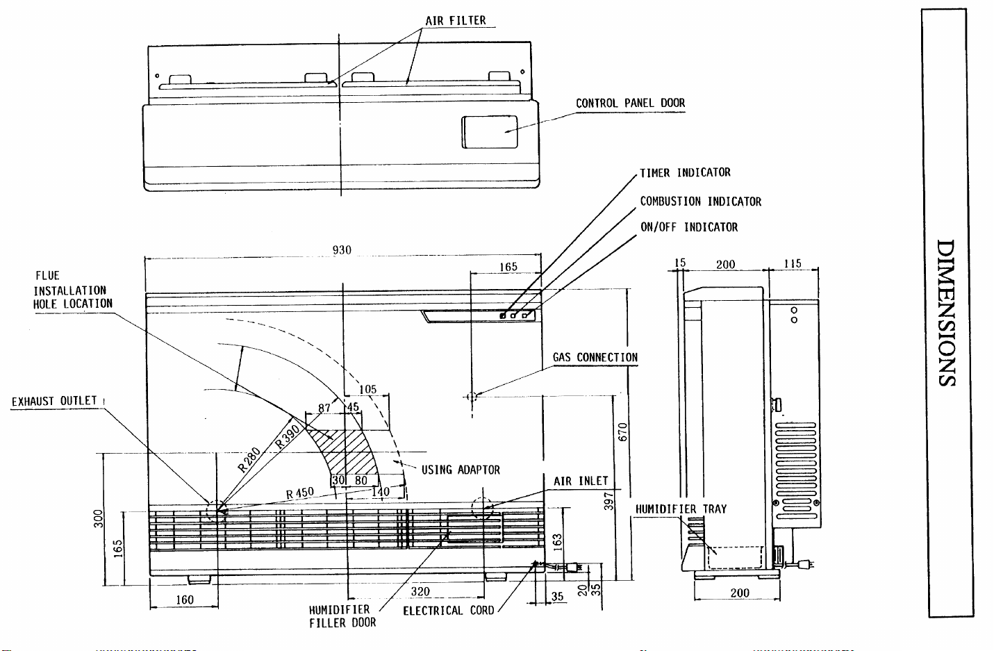
DIMENSIONS
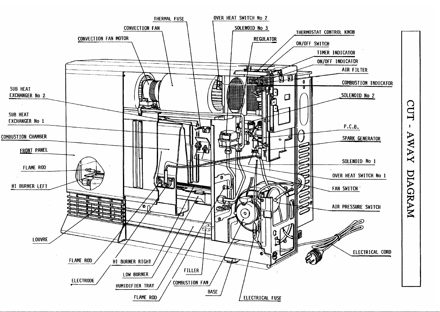
CUT-AWAY DIAGRAM
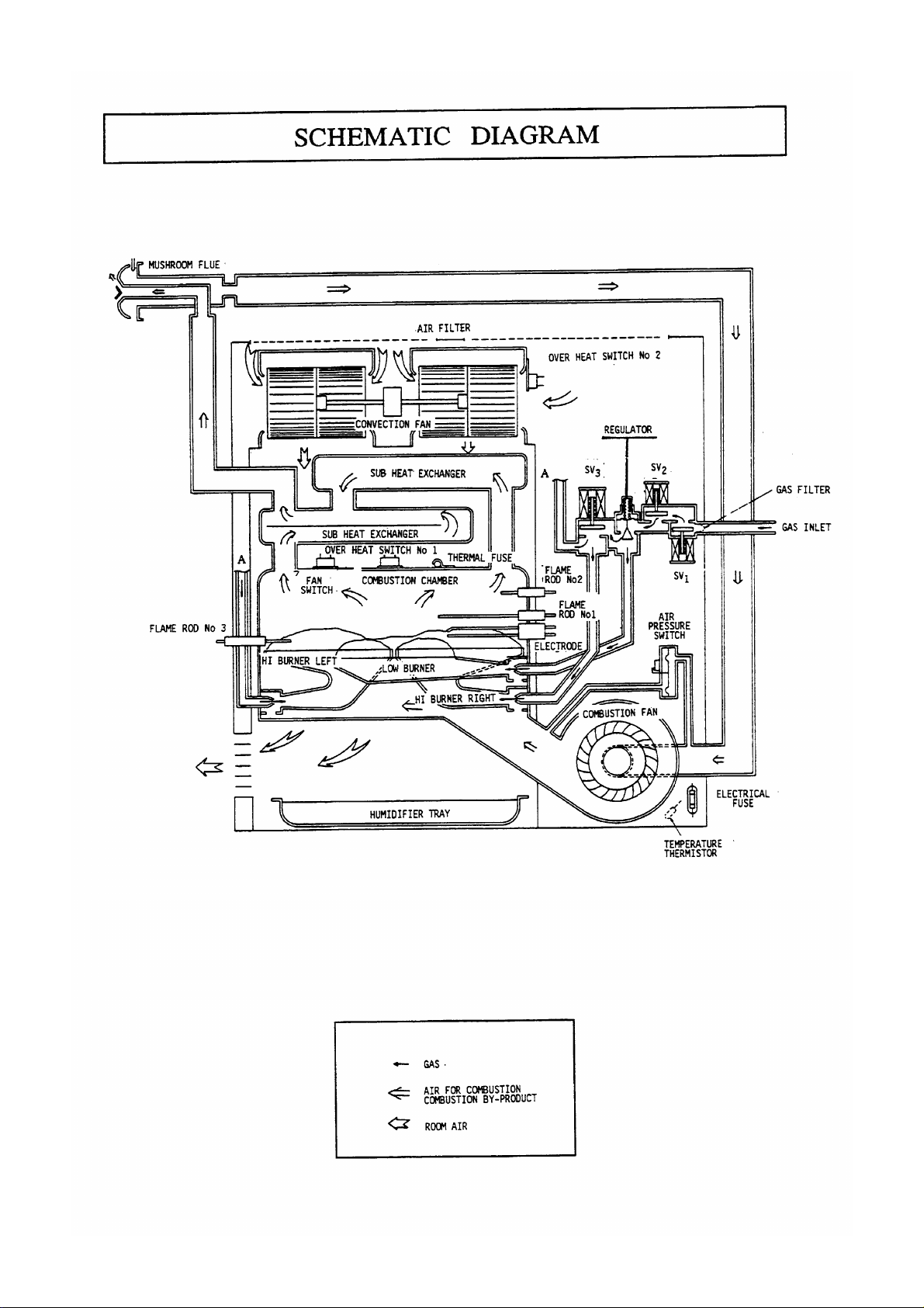
SCHEMATIC DIAGRAM
OPERATION
IGNITION SEQUENCE ANALYSIS
TIME CHARTS
TIME CHARTS
DIAGNOSTIC POINTS
WIRING & BLOCK DIAGRAMS
DIAGNOSTIC POINTS
-T
- FT/VA
-T
-T
- FTfVA
14 - 15
2
3
4
5-7
8
9
10
11
12 - 13
16 17
18
19
20
WIRING & BLOCK DIAGRAMS
OPERATIONAL FLOW CHARTS
SAFETY DEVICES
OPERATION OF SAFETY DEVICES
FAULT FINDING
FAULT ANALYSIS
INSTALLATION
TRANSFORMER VALUES
ELECTRICAL COMPONENTS ANALYSIS
EXPLODED DIAGRAM
PARTS LIST
CONVERSION INSTRUCTIONS
DISMANTLING FOR SERVICE
CUSTOMERS OPERATING INSTRUCTIONS
- FTIVA
21
22 - 23
24 - 25
26 - 27
28 - 29
30-31
32
32
33- 37
38- 44
45- 49
50
51
-63
64- 65
FLUE SYSTEM
SERVICE NOTES
SERVICE CONTACT POINTS
66- 67
68
BACK COVER
Page 4
BACKGROUND
In 1983 the The RHF 1000 was launched onto the market in Australia. This was followed in
1986 by the launch of the RHFE-lOOlF, a completely new appliance with a new control system,
and compact lightweight design. The RHFE-lOOlT, released in 1991 is an updated version of
the
RHFE-1001F with the addition of a 12 hour slide timer. The
suited to commercial applications such as schools and small
domestic applications.
RHFE-1OOlFT
offices,
it is also ideal for large
is particularly
INTRODUCTION
* One
touch ON/OFF control.
*
Warm air distribution is from the bottom of the heater.
*
Three step automatic heat and fan control with the electronic thermostat.
*
Installation of the flue system requires only an 80 mm hole through a wall to the exterior of
the building.
*
The thermistor controls the room temperature within the range of 12.5 * 3°C to 35 + 7°C
with a differential of 1.5 +
*
In the event of a malfunction, one or more of the various safety devices will be activated,
ensuring complete safety.
OST.
The outer casing of the appliance is formed from 0.8 mm galvanised and painted steel, secured
to the main body assembly. The bodywork is formed from 1.2 mm galvanised steel sheet,
forming a casing to which the heat exchanger, blower assembly, solenoid valves, printed circuit
board and other componentry is attached.
The general layout of components is shown in the cut-away diagram on page 9. The heat
exchanger is composed of two (2) sub-heat exchangers which are constructed from 0.5 mm
stainless steel sheet. A combustion chamber is connected to the sub-heat exchangers, which in
turn are connected to the flue system.
The combustion chamber, constructed
occupies the middle of the appliance. Its dimensions are 622 mm wide x 94 mm deep x 319 mm
high. The burner is composed of two (2) large burners and one (1) small burner. The large
burners are slit port
0.5 x 7 mm, and the number of slits is 103 for each burner. The small burner is also a slit port
bunsen
The air for combustion, both primary and secondary is supplied by a 134 mm diameter Sirocco
fan. The air is drawn
right hand side of the combustion chamber. The primary air ports are adjustable within the range
of 0 to 135
by a screw.
type made of 1 mm stainless steel sheet, with 95, 0.5 x 7 mm slits.
mm2
bunsen
by means of the aeration shutters. The aeration shutter adjusting rod is fixed
type, made of 1 mm stainless steel sheet. The burner slit sizes are
from
the outside enviroment through the flue system and into the lower
f?om
1.0 mm hot dip aluminium coated steel sheet,
Three injectors are mounted inside the gas connection tubes, where they connect to each burner.
The gas inlet connection is an R
%“/
15 male thread, located at the rear on the
left
hand side
Page 5
[viewed from the rear] and situated approximately 400 mm
through the inlet to the double block solenoid valve No.1 and No.2 , then on to the regulator
which supplies the gas to the (central )
connection tube, injector and finally into the lower part of the combustion chamber where it is
ignited on the burner. When the appliance is operating on HI, the gas also passes through
solenoid valve No.3 whic h in turn allows the gas suppl y to the HI burners to be ignited.
Prior to ignition any combustion product or raw gas remaining in the combustion chamber is
purged by the combustion fan, preventing explosive ignition or flame vitiation by any remaining
by-products.
Ignition is by the continuous spark method in conjunction with the solenoid valves and micro
switch. The spark is monitored and controlled by the printed circuit board. The spark gap is 3.0
f
0.8 mm. [Generated voltage is llkv]
The products of combustion pass through the combustion chamber and sub-heat exchangers,
heating the room air before being expelled outside via the concentric dual pipe flue system.
Ai r is drawn in through the steel mesh filters located at the top of the rear panel by the
centrifugal convection fans and blown onto the outer surface of the combustion chamber and
sub-heat exchangers, before passing over the open vessel type humidifier out into the room
through the louvres, located at the bottom front of the outer cover. The average humidification
is 300 cc/h WI setting].
LOW
operating burner via a 10 mm diameter alurninium
fro m
floor level. The gas passes
The humidifier tray is fabricated from 0.6 mm cold rolled carbon steel sheet, black enamellecl
with a maximum capacity of 3 litres of water. Any condensation in the flue manifold is drained
into the humidifier tray.
The warm air outlet consists of six (6) fixed horizontal louvres and eight (8) vertical adjustable
air guides.
DISTINGUISHING T & FT/VA
The
RHFE-1OOlF T
main difference is in the printed circuit board
The RHFE-lOOlFT/V A can be identified by the
appears printed on the printed circuit board. The
1OOlF A
This manual provides information on servicing and fault finding for both FT and
versions. Where data differs between the appliances, seperate sets of information are provided.
The differing information is: time charts; diagnostic points; block and wiring diagrams;
operational flow chart; electrical component analysis; and parts list.
and has a ceramic resistor attached to it by 2 white wires.
and the RHFE-1OOlFTN A are basically the same appliance. However, the
P.C.B. ]
markin,,
and its related wiring harnesses.
a
Rinnai-RBC
RHFE-1OOl T
RHF-lOOlF(VA) ,
P.C.B. is marked
which
RHFE-
FTNA
All other information is common to both appliances.
Please ensure that yo u have identified the heater correctly before attempting servicing as
well as when ordering spare parts.
Chang e to FT/VA model
occure d
in September 1992
Page 6
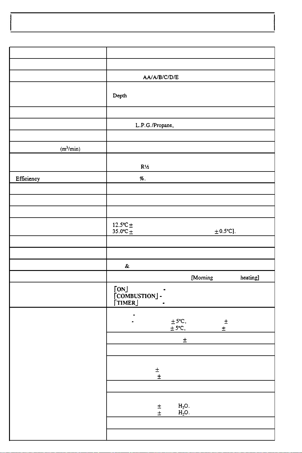
SPECIFICATION
Type of appliance
Model
Exhaust system
Dimensions
Weight
Gas type
Gas controls
Heated air volume
Connections
Efficiency
Combustion system
Ignition system
Temperature control
Temperature range
(m3/min)
Forced flue gas space heater.
-
1001 FT. RHFE - 1001 FTNA.
RHFE
Mushroom -
Width = 930 mm.
Depth
Height
41 Kg [Standard].
Natural,
Solenoid and combined regulator.
HI - 8.1 LOW
Electrical - 240 V
Gas
Approx 85
Forced combustion with stainless bunsen burner.
Automatic flame sensing continuous spark.
OFF
-
12.s0c + 3°C [LOW).
35.O”C k
AA/A/B/C/DIE
= 330 mm with spacers.
= 670 mm.
L.P.G./Propane,
-
5.0
50
Hz.
-
RX
(l5mm).
%.
MED - HI [Slide mechanism]. Electronic thermostat control.
7°C [HI-j.
Differential of 1.5
Co-axial approved.
T.L.P.
[NZ:
230 V 50 Hz].
& OYC].
Warm air outlet
Humidifier tray capacity
Fan control
Timer operation
Indicators
Safety devices
Bottom of appliance at front. [Adjustable]
Approx 3 Iitres. Evaporation rate 300 cc/h.
& Fan switch.
PCB
12 hr delay slide operated timer.
-
rONJ
rCOMBUSTION] -
rTlMERJ
O.H.S.- Bi-metal.
No.1- OFF app 130 +
No.2 - OFF app 65 +
Thermal fuse Flame failure - flame rod. Flame rectification]
Fan switch - Bi-metal.
ON- 60 + 5°C.
OFF Power failure -Power failure circuit.
Air pressure -
- 6.0 & 2mm
ON
OFF - 4.8 + 2mm H,O.
green.
red.
-
green.
Melt s at 152
+ 5°C.
43
Air pressure differential.
Morning
ON app 110 + 10°C.
YC,
ON app 50 + 10°C.
5”C,
+
2°C.
H1O.
or evening
heati@
Power surge- 5 Amp fuse.
Pre-ignition
- Spark sensor.
Page 7
I
1,
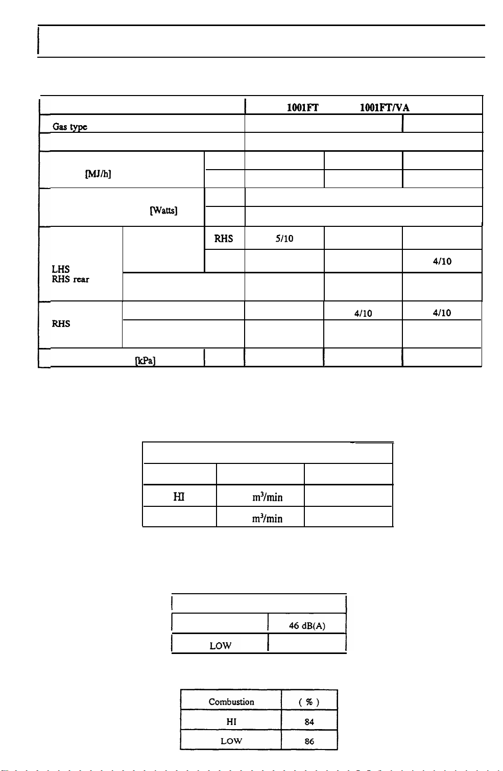
COMBUSTION SPECIFICATION
PERFORMANCE CHARACTERISTICS
I
Model
G=typc
Combustion method
Input
Electrical Consumption
HI burners
LIiS
RI-iSX-ar
burner
LOWburner
R&IS front
Regulator pressure
mJ/h]
Damper
Opening
burner
Injector
Damperopening
injector
Fprt]
HI
LOW
HI
watts]
LOW
RI-IS
LHS
size
size
HI
RHFE - 1OOlFT
Natural
Stainless steel
37
14.5 18.6
s/10
5/10
1.65 mm
x2
7110
1.75 mm
Xl
0.98
RHFE-
I
bunsen
I
1OOlFTNA
T.L.P.
type burner.
37 38
110
65
5/10
5/10
3.25 mm
x2
4110
3.25 mm 1.05 mm
xl xl
0.45
Propane/L.P.G.
16.5
4110
4110
0.95 mm
X2
4/10
I
2.75
2.
OPERATING NOISE LEVELS
3. EFFICIENCY
Convection Fan
Air Flow
HI
LOW
I
I
8.1
m3/min
5.0
m3/min
Standard noise levels
HI
I
35 dB(A)
Fan Speed
840
510 rpm
_
rpm
Page 8
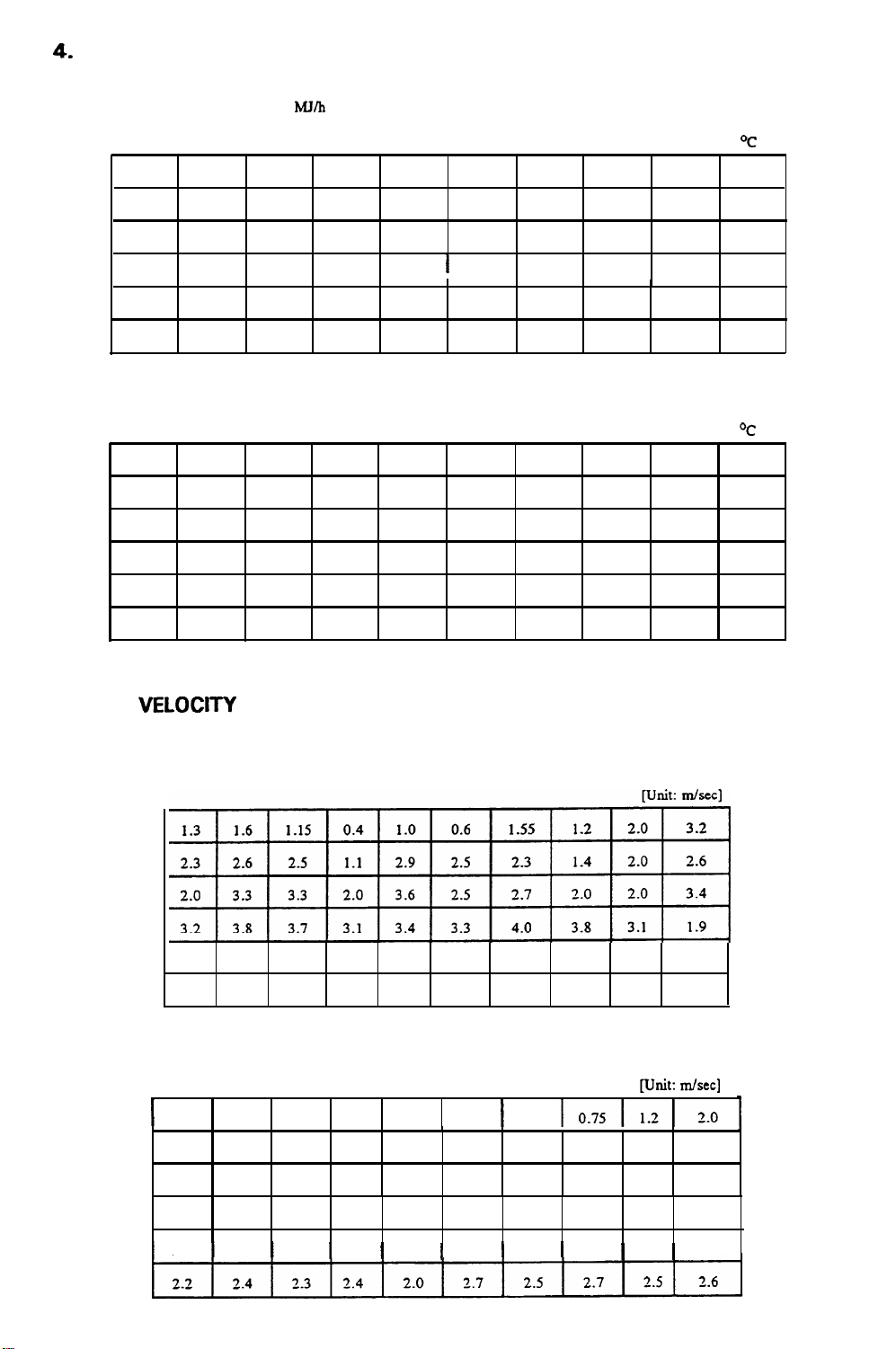
LOUVRE TEMPERATURES
4.
HI Combustion
54
80
78
58
61
60
LOW Combustion
30
38
38 35
31
30
30
59 66
82
62
54
53
54
36
45
30
28
29
:
38
Input
Input
MJRI
36 32
86 80
63 94
55
52 70
52
:
14.5 MJ/h
46 36 34
60
40
33
29
28
77 75 ’ 63
74
61
68 46
47 44
40
40
52
69 85
72
76
73
60
42 34
42
77 64 68
61
57
43
71
51
34
33
Temperatures are above ambient.
72
85 63
61
59
55
49 26
59
39
33
32
31
45
59
59
58 58
36
37 30
31
31
30
37
67
53 56
55
55
34
35
30 29
30
31
unit: oc
Unit:
OC
44
51
52
56
26
30
30
30
5.
AIR
VELCKXI-Y
HI Combustion
LOW Combustion
I
3.8 4.0 3.8
3.4
4.1
0.7 0.7 0.65
1.55 1.7 1.7
1.05 1.95 1.9
1.8
2.2 2.2 1.7 2.1 1.95 2.5 2.0 1.7 1.3
3.7
3.8 3.6 3.9 4.2 4.3 3.5
3.9 3.9 3.9
3
._
0
0.7
1.0 2.0
0.7 0.6
1.45
4.1 4.1
1.35
1.5
0.95
1.45
1.8
0.8
I.15
4.2
[Unit:
1.2
1.0
3.8
m/set]
I
1.7
1.9
2.2 2.4 2.3
1
2.3
1
2.0
2.5 2.6 2.5
1
1
2.0
1
Page 9
SURFACE TEMPERATURES
6.
Temperatures were taken with the appliance operating on Natural Gas at 38
AI1
temperatures shown are “C above ambient.
In
x
II
x
In
X
c
W/h.
X
N
%
-11
Page 10
Page 11
Page 12
Page 13
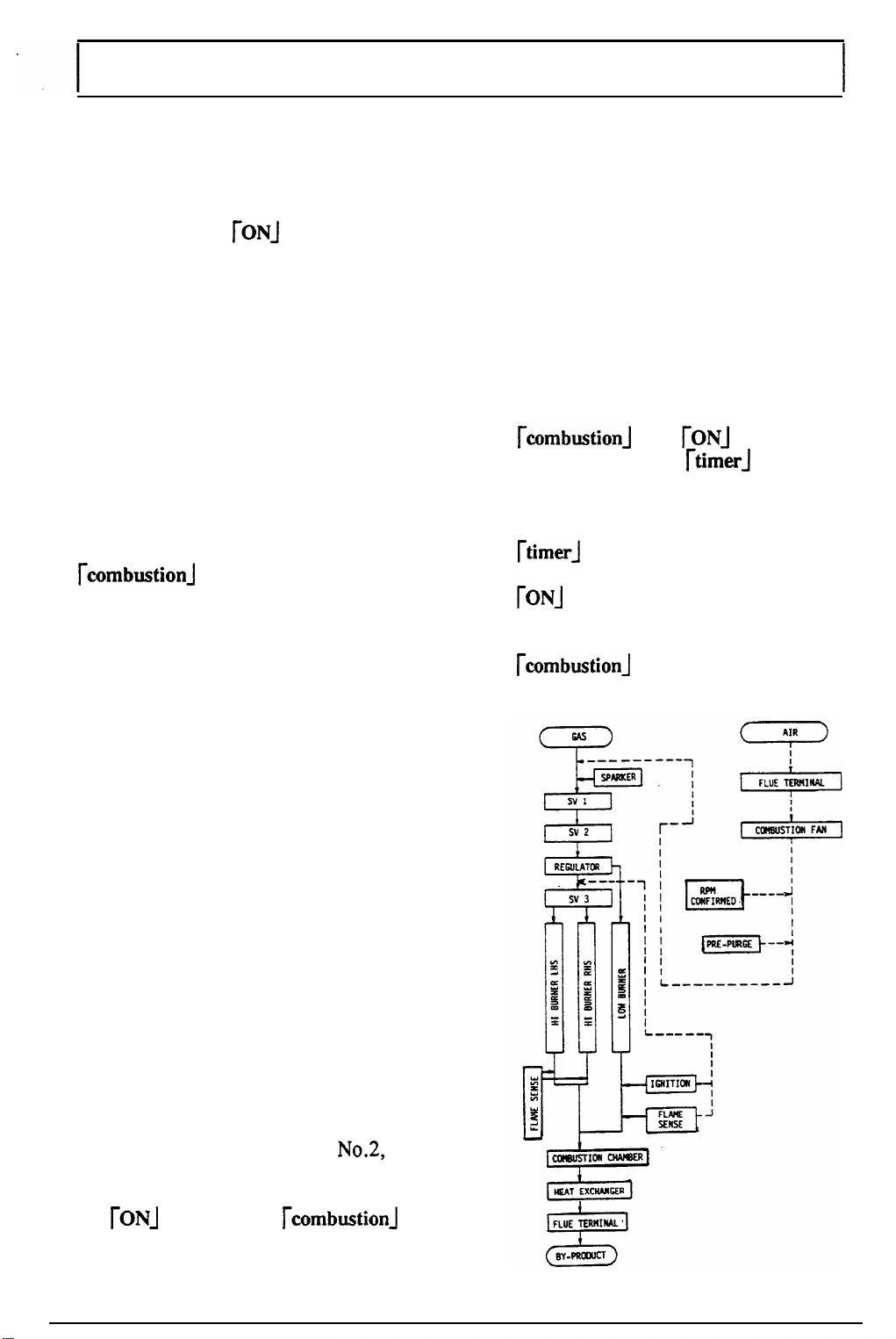
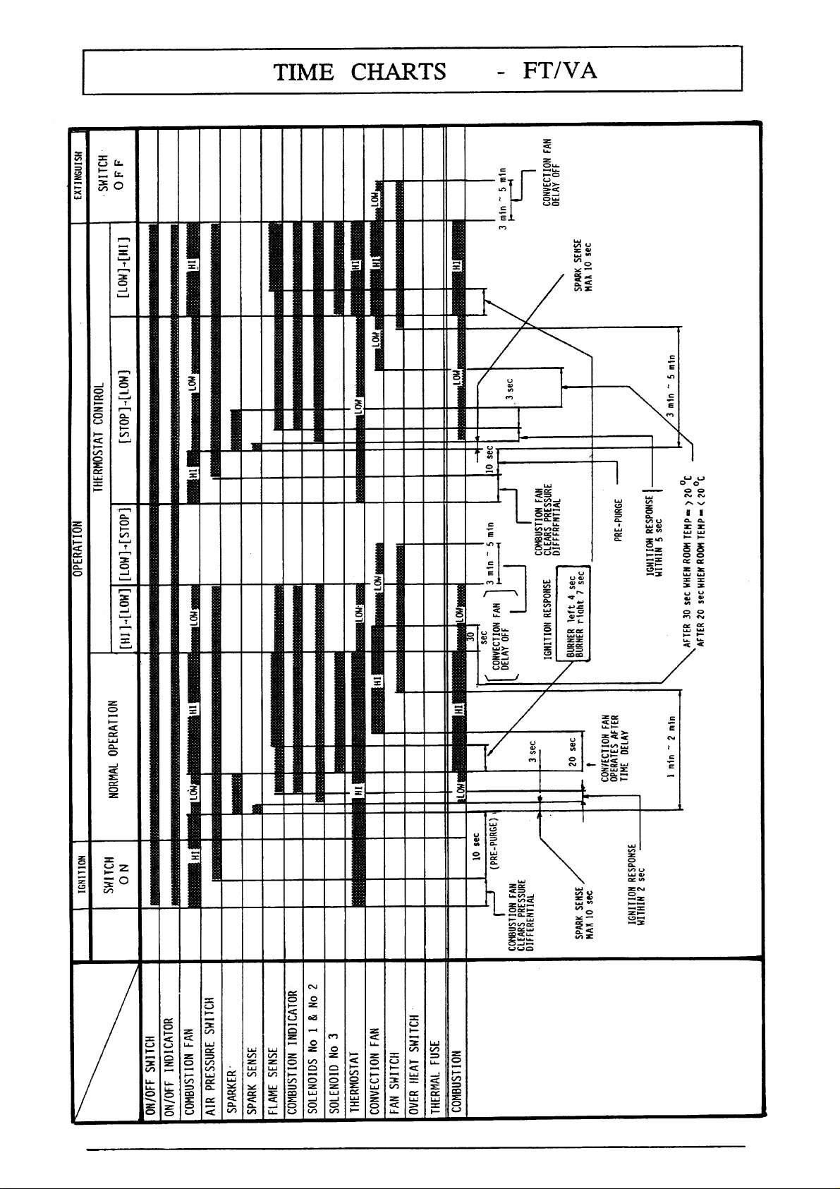
OPERATION
Normal Operation Operating the Timer
After the ON/OFF button is set to the
ON position, the
glow. The combustion fan will begin to
rotate, and pre-purge begins.
As pressure rises in the heat exchanger
the pressure switch will operate, and
after approximately 10 seconds the spark
will occur.
The spark sensor checks that the spark
has
occured
Solenoids No.1 and No.2 will open to
allow the gas to flow and ignite on the
LOW burner [LOW combustion]. When
the flame rod senses the flame, the
rcombustionj
As the spark ceases, solenoid No.3 will
open allowing the gas to
on the HI burner
depending on the thermostat position.
Approximately 30 seconds after the flame
rod senses the flame, the convection fan
will begin to operate, and warm air will
flow through the louvres at the front of
the appliance.
across the spark gap.
rONJ indicator will
indicator will glow.
flow
and ignite
[HI
combustion],
Press the ON/OFF button to the ON
position. Position the thermostat control
knob in the desired position. Decide upon
the number of hours delay after which
you would like the heater to begin
heating, and move the vertical slide timer
select knob accordingly. If the delay is
less than 2 hours, the slide timer
should be moved to 12 hours then back
to the desired delay. The
rcombustion]
will go out and the
will glow.
When the time of ignition arrives, the
[timer1
ignition sequence will occur and the
[ON] indicator will glow.
When
rcombustionj
and
rONj
indicators
[timer-J
indicator will go out, the
the burner ignites, the
indicator will glow.
indicator
Room Temperature Control
Temperature is selected by positioning
the horizontal thermostat control knob to
the desired locationalong the slide.
Turning OFF
After the ON/OFFbutton is set to the
OFF position, solenoids No. 1,
No.3 will shut off the gas supply to the
burners and the combustion fan will stop.
The
rONA
indicator and
indicators will go out. Several minutes
later the fan switch will turn off, and the
convection fan will stop.
rcombustion]
No.2, &
Page 14
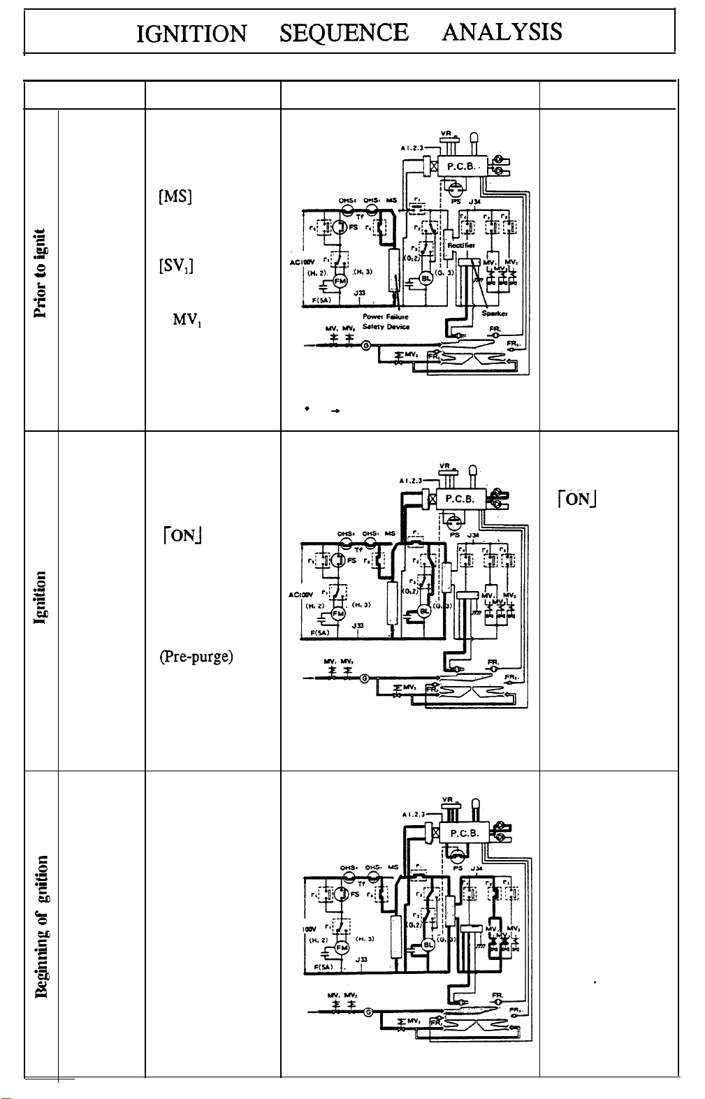
Action
Operation
Gas passage & electrical circuitry
Remarks
Insert
plug into
wall
socket.
c
0
.I
Y
rrl
5
.-
0
b
.I
k
ON/OFF
button to
ON
Current
through to
micro switch.
[MS]
Gas through
to solenoid.
ISVJ
= sv,
MV,
MV, = SV,
MV, = SV,
Micro switch
[MS] is
activated.
*
240 + 100 inside appliance
position.
TONJ
indicator
5
.-
d
.C
&
glows green.
AC
Combustion
fan operates
on HI.
(Pre-purge)
No obstacles
in gas supply
connection tube.
If there is air
in the supply
line, then it
will take time
to ignite the
appliance upon
initial ignition.
Confirm power
supply if
r0NJ
indicator
doesn’t glow.
If ON/OFF
button is in
ON position at
time of placing
electrical
plug into wall
socket, unit
won’t operate
due to power
failure safety
circuit.
Air pressure
switch is
activated. Spark
g
.II
Y
.I
5
.I
CL
0
z
-4
z
.L
2
#
occurs
approximately
10 seconds after
current passes
through the
P.C.B. unit.
Solenoids SV,
&
gas ignites on
the LOW
burner.
SV, open and
AC
Spark sense
checks that the
spark has
occured
across the
spark gap.
Combustion
fan operates
from HI to
*
LOW
Page 15
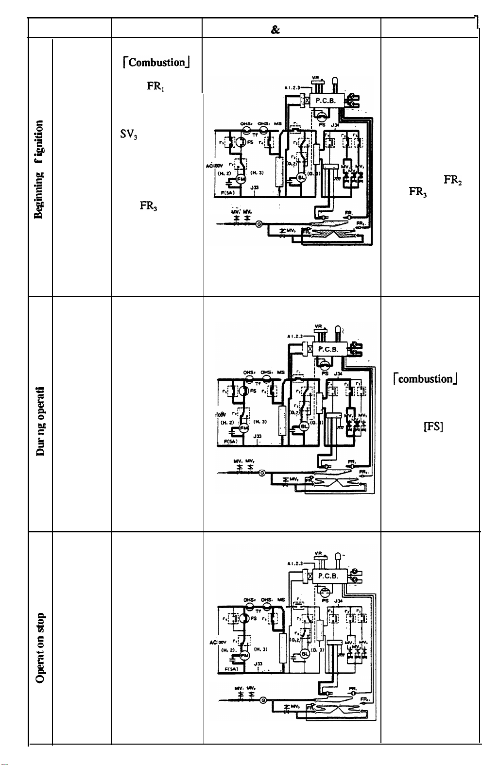
Action
Operation
Gas passage & electrical circuitry
Remarks
[Combustionj
indicator glows
after
senses a flame.
5
.-
U
.”
EE
.cr
0
z
.C
g
‘Eb
&
2 seconds later
SV,
combustion fan
operates on HI.
Combustion
continues as FR,
and
flame.
Convection fan
operates with in
32 seconds of
flame sense.
Position
the temp
control
knob to
the
desired
8
.-
position.
3
As the
thermistor
senses the room
temp, the
P.C.B. adjusts
the burner
setting
automatically.
$
?
.I
L
a’
The convection
fan operates for
30 seconds on
HI after burner
setting changes
to
FRI
opens and
FR,
sense a
LOW.
AC
Mu; uvr
Two attempts at
ignition occur.
Appliance will
lock out if
ignition does not
occur the second
time.
Appliance
locks out if
FR2
and FR, cease to
sense a flame.
When the
appliance
modulates from
LOW to OFF,
the
rcombustionj
indicator goes
out, within a few
minutes the fan
switch
IFS]
goes
OFF and fan
stops.
ON/OFF
Solenoids close.
button to
OFF
position.
3
m
E
.I
z
%
0”
Combustion fan
stops operating.
After a delay,
fan switch goes
OFF and the
convection fan
stops.
The electrical
plug must not be
removed from the
wall socket whilst
the convection
fan is operating.
Page 16
Page 17
Page 18
Page 19
Page 20
DIAGNOSTIC POINTS -FT
Note:
Main switch Blue - Red
Over heat switch No. I
Over heat switch No.2
Thermal fuse Blue
LED 1 Yellow
LED 2
LED 3 Red
Combustion fan
Air pressure switch white - White
Numbers under wire colours indicate pin markers on wiring diagram. See page 19
MEA- POINTS
COMPONENT
I
WIRE
coLouRs
Blue - Blue
Red
White
White - Orange
4
VOLTAGE OR
RESISTANCE
VALUES
I
I
-
Blue
-
White DC 14 - 23 Volts
-
White
-
Black
-
Black
- 5
I
I
Below AC 1 Volt
Below AC 1 Volt
Below AC 1 Volt
Above 1 M
DC
30 - 40 Volts
AC 90 -
AC 90 -110 Volts LOW
Below DC 1 Volt
110 Volts HI
120 - 180
200-3OOs2
Q
Q
Flame rod No.
Flame rod No.2
Flame rod No.3 Blue - F R
Solenoid
SolenoidvalveNo.2
SolenoidvalveNo.3
Convection fan
Sparker
Fan switch
1
valveNo.
1
I
Yellow
White -Blue
White
White-Black
White - Red
White
Red
White - White
-
F R
13
Red
-
F R
12
11
29 -30
-
Blue
29 -30
29-31
-
Black
-
White
-
29
28
AC 90 -
AC 90 -
I
Above 0.8
DC 80
DC 80-
DC 80
DC 80 -
-
110 Volts
1.3
-1.8 k
110 Volts
1.3
-1.8 k
100 Volts
-
1.3
-1.8 k
110 Volts LOW
100 - 140
110 Volts HI
50 - 70
100 Volts
Above 1 M
Below AC 1 Volt
PA
Q
Q
Q
f2
Q
Q
Thermistor Yellow - Yellow
-
Red
Slide control
Ceramic resistor
White
9
-
8
White - Black
9
-
10
White
-
White 1.8 k
Approx 30 k
10°C
=$
app 65 k
20°C 9 app 39 k
Q
- 0
OQ- approx 30 k
C?
Q
Q
Q
!I
Page 21
Page 22

DIAGNOSTIC POINTS
-
FT/VA
N0t.C
FC - refers to the numbers in circles on the flow chart at the Iefi of the sequence. [see page
WD - refers to the position of the connections on the wiring
Numbers under wire colours indicate pin markers on
MEAsuREMEhT
FC COMPONENT
113
PI ’
PI
[41
Main switch
O.H.S. No.1
Thcxmal
fuse
O.H.S. No.2
Timer
transformer
LED 2 assembly
Combustion fan
Air pressure switch
POINTS
F,
G,
G,
G,
C*
C,
G,
Sparker
diagram.[see
wiring
diagram.
WIRE
COLOIJR
Brown - Red Below AC 1 Volt
Grange - Orange Below AC 1 Volt
Orange - Orange
Orange - Blue
Yellow - Yellow AC 20
white -
Yellow
-
Black
White
white -
orange
Brown
-
Brown
6 7
Blue
- Grey
37
38
page
211
VOLTAGE
VALUES
Below AC
Below AC I Volt
DC 14
AbovelMO
AC90
120 - 180
-
AC 90
200 -
Below DC 1 Volt
DC 80
AbovelMQ
OR
RESISTANCE
I
Volt
-
28 Volts
-
23 Volts
110 Volts HI
-
110 Volts LOW
3000
-
100 Volts
231
n
Solenoid No. 1
Solenoid No.2
Flame rod No.1
1111
LED 1 assembly
Slide thermostat
w1
Thermistor
1131
Solenoid No.3
1141
’
Convection fan
WI
Fan switch
Air pressure switch
Black - Grey
33 SV, 36
Blue
34
Yellow - FR,
C,
A
B
H
F,
White - Red DC 14 - 23
White -
white -
Yellow - Yellow
white
35
White - Black AC 90
White - Red AC 90 -110 Volts LOW
Yellow
Brown
-
Grey
SV, 36
16
Red
Black
4 5
- Grcy
SV, 36
-
Yellow
-
Brown
6
-
7
DC 80 -
DC80 -
App 30 k 0 - 0
OR
10°C =
2K *
DC 80 - 100 Volts
Below AC 1 Volt
Below DC 1 Volt
lOOVolts
1.8 k
1.3
-
lOOVolts
1.5 k
1.0
-
Above 0.8
Above 1 M
- app30kO
app 65 k
app 39 k
1.8 k
-
1.3
110 Volts HI
-
50 - 70
100 -
1409
Above 1
R
R
/LA
Volrs
Q
Q
Q
M R
fl
Q
Q
Flame rod No.2
Flame rod No.3
LED 3 Assembly
Red
- FR,
15
Blue - FR,
14
-
Black DC 30 - 40 Volts
Red
Above 0.8
Above 0.8
fi
PA
Page 23

Page 24

Page 25

Page 26

SAFETY DEVICES
PRE-PURGE
This circuit ensures that fresh air is provided for mixing with the gas supply before ignition
occurs, as well as clearing the combustion chamber of any previous products of combustion
which may have remained since the last combustion cycle.
AIR PRESSURE SWITCH
The air pressure switch confirms the operation of the combustion fan, and confirms that
sufficient air for combustion isflowing through the appliance.
-
ON pressure differential
OFF pressure differential
SPARK SENSOR
6.0 * 2mm
-
4.8 + 2mm
H,O }
H,O ]
Water
Guage
Confirms that the spark has crossed
the solenoid valves are opened only
FLAME FAILURE SYSTEM
Confirms that the main burner is alight (or extinguished). If the ignition cycle is incomplete or
the flame fails, and the flame rod current drops below 0.1
Ignition sensing occurs above 0.8
OVER HEAT SWITCH
Shuts
blockage or convection fan breakdown.
CONVECTION FAN DELAY CIRCUIT
The PCB turns the fan ON, however after the flame is extinguished, the fan switch will remain
ON, depending upon the residual heat inside the appliance, this is to prevent overheating
occuring
off the
Over Heat Switch No.1
Over Heat Switch No.2- OFF app 65 &Thermal Fuse
as well as increasing efficiency. The fan will remain ON until 43 + 5°C is reached.
gas
supply by closin,
the spark gap correctly. In order to prevent miss ignition,
after the spark location has been sensed as being correct.
PA,
then the solenoid valves close.
PA.
0
the solenoids in the event of any overheating, louvre
-
OFF app 130 + 5°C ON app 110 +
5”C,
ON app 50 k 10°C
-
Melts at 152 + 2°C
10°C
from
POWER FAILURE SAFETY DEVICE
In the event of a power failure or power cut the solenoids will close immediately. After the
power is re-instated the appliance must be operated manually. ie: Turn OFF then ON again.
OVER CURRENT PROTECTION
5 Amp fuse will blow and the appliance will lock out.
Page 27

THERMISTOR
The thermistor is a semiconductor which reacts
to changes in temperature by altering its
RELATIONSHIP BETWEEN
RESISTANCE
&
TEMPERATURE
resistance. The relationship between temperature
and resistance is outlined in the graph. The
resistance value is detected electronically, and
activates the amplification circuit, which in turn
operates the gas input control circuit [temperature
control].
I
TEMPERATURE
b
Compared to the previous types of thermostats [Vapour pressure and Liquid expansion],
thermistors offer increased sensitivity, as well as a lower
differentiaI
enabling precise
temperature control.
FLAME RECTIFICATION
Flame rectification is
utilised
to check flame presence. A flame sensing electrode consisting of
a stainless steel rod supported in a ceramic insulator [flame rod] is positioned above the main
burner. An
body of the burner and the flame guard amplifier
a.Itemating
current is applied to the flame rod by the flame guard amplifier. The
FGA]
are both earthed.
The principle of flame rectification relies on the ability of the flame to conduct positively
charged ions more easily than negatively charged ions. This characteristic is called flame
rectification, as the current leaving the burner, having passed through the flame, is no longer
an alternating current. The signal returning to the FGA has been rectified by the flame, this
signal is used to determine flame presence.
The signal can only be produced by the flame. Short circuits, dirty contacts and other fault
situations cannot simulate the rectified signal. The FGA section of the P.C.B. sends an amplified
signal to the main P.C.B. to indicate flame presence,
n
FLAME ROD
e
t) ’
IOY -
DIRECTION OF
ALTERNATING CURRENT
AC 200 VOLTS
allowing the gas valves to remain open.
MAIN
\
BURNER
FLAME GUARD
AMP
-I
P.C.B.
c---
GAS VALVE CIRCUIT
1-4
SOLENOID
1
Page 28

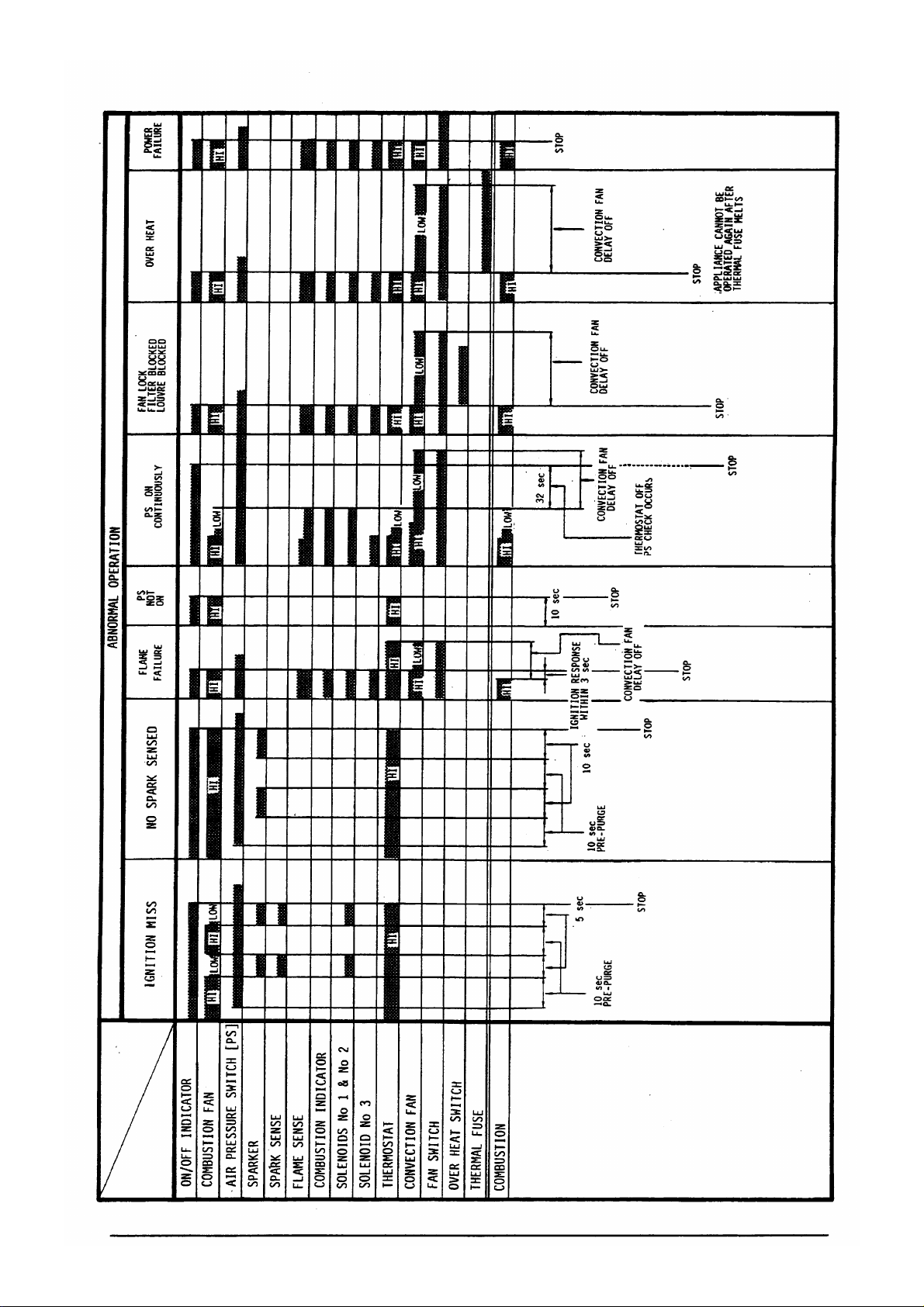
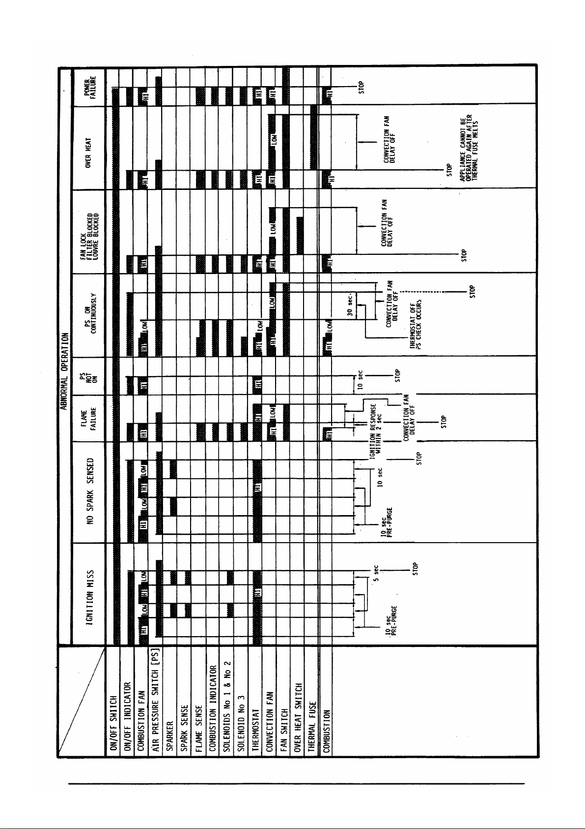
OPERATION OF SAFETY DEVICES
NATURE OF FAULT
FLAW FAILURE
* No gas.
* Miss ignition.
OVER
HEAT
*
Fan not
operating.
*
Over gassed.
*
Blocked filter
or louvre.
* Obstruction at
front of
appliance.
POUER
FAILURE
* Power cut
during normal
operation.
* Power cord
disconnected.
SAFETY DEVICE SEQUENCE
ACTION REQUIRED
*
Check for any kinks,
blockages or breaks in the
gas supply.
*
Check that the flue
terminal is not obstructed
in any way.
* Reset ON/OFF button and
try to operate appliance
again.
*
Check for blocked injector
and aeration shutter.
over heating.
*
Check fan.
*
Check injectors.
*
Reset ON/OFF button and
try to operate appliance
again.
FUSE
BLOWN
*
Power surge
*
Short circuit
inside
appliance
.
, * locate and remove the
cause of the excessive
electrical current.
*
Replace the 5 Amp fuse.
Page 29

NATURE OF FAULT SAFETY DEVICE SEQUENCE
SPARK
SENSOR
*
Confirmation
of the spark
between the
spark
electrode and
the spark
sensor fails.
Solenoids don't open.
PRESSURE SWITCH
*
Confirms that
the combustion
fan is
providing
sufficient air
for
combustion.
I
ACTION REQUIRED
* Check the spark gap.
* Investigate the cause of
the spark sequence not
being completed.
NORMAL OPERATION
r
FANDElAY
*
Convection fan
continues to
run after the
flame has gone
Out*
PRE-PURGE
* Expels any
previous
products of
combustion or
raw gas from
the combustion
chamber before
ignition.
SEQUENCE
IGNITION
Page 30

FAULT FINDING
NATURE REMEDY
Ignition does not occur
after having switched the * Check gas type
appliance ON.
* Check gas supply
*
Air in gas supply
*
Flue manifold obstruction
[see
...................
...................
...................
...................
following]
1
1
:
Room does not warm up.
Flame Failure.
There is a smell of gas.
* Position of thermostat
*
Blocked air-filter
*
Insufficient gas supply
*
Warm air short circuit
*
Blocked flue terminal
* Blocked air filter
*
Power failure
*
Obstruction in front
*
Gas type
* Blockage in gas supply
* Check gas supply and appliance
...................
................... f
...................
...................
...................
................... z
...................
...................
...................
...................
...................
1
4
8
4
7
7
1
DISTINCTIVE CONDITIONS CAUSES AND REMEDY
Gas
supply [non-ignition, not warming up,
*
Is there sufficient gas pressure, and is the gas supply clear of air, kinks or obstructions of any
smeI1
of gas].
nature? Check for gas escapes.
Thermostat control
[room doesn’t warm up].
Is
the thermostat control knob in the LOW position?
=
Move the knob to a higher setting.
Blocked air filter [no gas, room doesn’t warm up].
Check that the air filter is clear of dust. If the filter is blocked then the O.H.S. safety device
may have been activated. In extreme cases the thermal fuse may have melted thus preventing
ignition from
=S
Clean filters thoroughly and re-operate the appliance.
3
Ensure thermal fuse is O.K.
4
Louvre obstruction [no gas, room doesn’t warm up].
occuring.
Is there a one (1) metre clearance in front of the appliance? Also check to see if there is
anything blocking the louvre or convection fan. An obstruction may be causing air to divert back
Page 31

to the thermistor.
*
Remove any objects in front of the
FIUe
system.
appIiance.
Blocked flue system.
-
Ensure that the flue system is clear of any obstructions.
Flame failure.
Blockage in the flue system. Dust or foreign material inside the combustion chamber.
*
Check these areas as well as the gas pressure and type.
Power
*
failure
When the power fails for more than 0.2 seconds, the appliance will lockout. To reset, push
the ON/OFF button to the OFF position and then ON again.
CONDITIONS THAT ARE ARE NOT FAULTS
COHDITIOW
The convection fan continues to
run after the appliance is
switched OFF.
A clicking sound when the burner
lights.
A resonant sound shortly after
ignition.
The interior of the appliance must cool
sufficiently before the convection fan
will stop. This is to ensure that there is
no overheating and also increases
efficiency.
This is the normal ignition sound, and the
extent of the sound will vary depending
upon the pressures and
the burner.
This is the movement of the flame as it
travels across the burner.
EXPIANATION
temerature of
The heater will not ignite when
being first test fired.
There is smoke or an unusual smell
upon initial use.
After ignition there is a ticking
or clicking noise.
The flame goes out while
operational, however the
indicator remains on.
rmJ
There may be air in the gas supply
preventing the appliance igniting
Mediately. After two (2) cycles of 15
seconds the spark will
will lock out. The ON/OFF button must be
re-set to re-attempt ignition.
Caused by grease, oil or dust in or on the
heat exchanger. This will stop after a
short period.
This is the expansion of the combustion
chamber metal.
The room temperature has reached the
temperature selected on the thermostat
control. When the room temperature drops,
ignition will automatically re-occur and
combustion will continue.
stop and the heater
Page 32

FAULT
AFTER
HAVING OPERATED THE APPLIANCE AND:
l-
The
cahstion
time,
2. There is
3, The solenoids do
4.
The convection fan does not begin to rotate.
IKI
spark.
fan
dwsn’t kgin
not
open, preventing gas flow to the burners.
to rotate, or it suddenly stops after having run for a short
ANALYSIS
Is there electrical supply?
v:s
1
a
1. Broken wiring or loose pin connector on P.C.B. or on wiring loom.
2. ON/OFF button faulty.
3. Faulty P.C.B.
4. Over heat switch is in the OPEN position. [Closed
5. Thermal fuse blown.
6. Solenoid circuit faulty.
7. Air pressure switch faulty.
b
i
1. Combustion fan shaft
2. An obstruction in the combustion fan is preventing it from rotating.
3. Open circuit or bad connection in motor circuit.
4.
The flame current was greater than 0.8 PA during
5.
Weak or shorting spark.
I
6. Faulty P.C.B.
C
1. High tension cord disconnected or broken.
2. Insulation leak from the high tension cord. [The spark sound is not regular]
3. The spark gap is not correct. [Normal spark gap is 3.0
4. Weak or shorting spark.
5. Faulty P.C.B.
The appliance does not operate.
I
1
The combustion fan doesn't rotate or the appliance fails after a short time.
allen
1
There is no spark. [Spark not audible or sounds irregular]
-NO
e
screw loose.
Confirm the connection at the wall socket.
1
2
Is the 5 amp fuse blown?
=
Normal]
pre-purge.[False
*
0.8
flame check]
IITII]
3
1
d
/
The solenoids will not open.
1. Wiring or pin connectors have come out of place. [P.C.B. or wiring loom]
2. Solenoid coil is broken.
3. Faulty spark. [No spark sensing]
4. Faulty P.C.B. [No DC 90 volt circuit to solenoid]
1
e
1.
Convection fan grub screw loose.
2. An obstruction in the convection fan is preventing the fan from rotating.
3. Open circuit or bad connection in motor circuit.
4. The ceramic resistor is faulty.
5. Faulty flame rod.
I
6. Faulty P.C.B.
The convection fan will not rotate.
Page 33

After repeated efforts to operate the appliance, it wilt not ignite.
1.
Air in the gas supply.
2. Incorrect gas pressure.
3. Incorrect gas type, or a kink or break in the gas supply.
4. Faulty spark.
5. Blocked injector.
There
is
the soundof ignition,
After two (2) cycles of 15 seconds the spark stops and miss ignition occurs.
Is it the correct specification?
hamerthe
rc&ustionJ
indicator
does
notameON.
Ignition OK
1
Confirm the flame rod current
Miss Ignition Indicated
1. Faulty lamp
2. Faulty
1
1
/
incorrect wiring.
P.C.8.
1
Has the electrical current
risen above 0.8
1
Yes 3. Check flame rod is firmly positioned.
Faulty P.C.B.
The
flare fails during
1.
Power failure. [Indicator out]
2. Safety devices are activated.
* Air filter is blocked and the
*
Obstruction in the flue system.
*
Blockage in the gas supply.
*
Gas pressure is abnormally low.
*
The area surrounding the flue terminal may be too constricted, hindering air flows in and out
of the flue terminal.
* Obstruction in front of the heater.
fi?
nomal
operation,
A
0.H.S
is activated.
Check combustion specification, gas type,
tlaveyx~ensured
positions, and also the wiring is not
Items in No.2 have been checked, but after ignition flame failure occurs.
that*
connectors areinthecorrect
broken any&n?
1
Flame failure safety
Confirm flame
c
Faulty P.C.B.
rod current is correct and stable at above 0.5
u:s
1
device will shut-down the unit.
1. Does the test point pressure, and injectors
conform to the specification?
2. Flame rod or burner may be in worn condition.
‘
fi.
i0
1
9
Page 34

I
NOTE
The information provided here is done
so only as a guide. For full details on
installation procedures you are advised
to contact Rinnai directly
250 mm
INSTALLATION
I
50mm
c
50mm
>
TlXANSFORh!IER
T2
Transformer terminal voltage
and resistance values
VALUES
-
240
voltage and resistance values
100 Supply transformer
ON
Red
-
Red
Yellow
E
Yellow
White
White
-
-
AC90 -
45 - 70
AC 180 - 220V
390
AC 12
1.8
-
550 a
- 15V
-
2.5
1lOV
Q
Q
Page 35

ELECTRICAL COMPONENTS ANALYSIS
Before proceeding with any dismantling, be sure to follow the instructions exactly
where disconnection of electrical or gas supplies is indicated.
Before proceeding with any of the following fault finding,
electrical supply, as well as confirming that all the connectors are firmly in the correct
positions.
Where ” # ” appears, it is to indicate that you should remove the electrical cord from
the wall socket before attempting to measure.
TABLE
TABLE A
SYMPTOM
The
rONJ indicator does not glow after
check that there is gas and
D
P-34
FTtVA
P.36
having switched the appliance ON.
TABLE
B
The electrical fuse blows when the
P.34
P-36
appliance is turned ON.
TABLE C
10 seconds after switching ON the appliance,
P.34
P-36
the [ONJ indicator goes out, and the burner
does not ignite.
TABLE
D
During the first 10 seconds after switching ON
P.35
P.37
the appliance, the combustion fan operates twice
from
HI to LOW before the indicator goes out.
TABLE E
TABLE F
TABLE
TABLE H
TABLE I
G
There is no spark generated and the
rcombustionj
indicator does not glow.
The appliance lights on the LOW burner
but goes to lockout after several seconds.
The
thermostat control does not modulate.
The flame goes out during normal operation.
Operation of the appliance continues as normal
but the
rcombustionj
indicator does not
glow.
P.35
P.35
P.35
P.35
P-35
P.37
P.37
P-37
P-37
P.37
Page 36

Relevant
Where
n
f "
values.
appears,
to
RHFE -1001
FK
it is to indicate that you should remove the electrical cord from the wall socket before attempting to measure
HIRE OF FAULT
.,: . . ._
:w!F&::: :_.:,:,’ :,,: j
: & +j$,:&$,& : Ii; ;, ‘, ,’
:
$$?@w&&T;g
.‘~appWadq 4y;,> .; j, I. .:
:.,:
*:.~::-‘f&&+
safety
$$%zc&z~~~js.,
I@s&@ff, w ":i,.
.
,_,_ ,,
._:
_...
“’
. .
_..’
..’
.’
” ,,: :_.:..:
._
:
_. :
:
”
._
_.
._
:
.:
.
_::
EfrqfE.:.tbe :‘I
: ,_ ., :
.::.
. . ,_ _,
:
.._. .
.,,
,,
.: .:
: ,i. :.
j: _..
.:,
_,_:
.
...,,
,,:__. . .
. .
:_.
I...
_:._
:.
. .
.:_
,.
,, .:. . .
.:..
!
‘.
.;
. .
T&B
:~~Iec&ig
;#w
fuse
is+
DWIIIIATIOW WIHr
IS
the electrical plug in the wall* Check the electrical connection
socket firmly?
normal?
the
G.H.S.
in the OFF position?
Has the thermal fuse blown?
Is the movement of the ON/OFF
button normal?
j
_.:
.:.
.>..
_:
1
,I
#2 Is
:
13
:.
.
14
‘:
.
: #5
Is the transformer O.K.?
:
.,
:.
: #6 Is
the electrical fuse blown?
..__.
f
7 Is the LED P.C.B. O.K.?
‘.
#I Is
the transformer O.K.?
Is the voltage
(TR
(TR
2)
2)
Dmc
POINT
and voltage.
*
Check the O.H.S. continuity.
* $$k
the continuity through the
*
With the appliance OFF, remove Blue - Brown
the connector and check the
;;;inulty of.the
-
red wires.
l
Check the resistance of the
transformer
* Check continuity of fuse.
l
Check the voltage of the white
ellow indicator connectin wire.
Lmfimation
the
first 30
aritching ON.
Check the resistance of the
transformer.
blue - brown,
_
mst
be
suomds
ade &ring
after
210 - 260 Volts?
App 0 Q - normal
AppOQ-
;r;Mi 0 fteds
- App - Q is O.K.
Red - Red
ii 72
App 1.8
App 3.0
-
APP I4
White- White
Red - Red
R
-
1.8 ^ 2.5
-
45 -70 Q
VALES
normal
-
70
-
White
-
2.5 Q?
-
6.0 Q?
-
23 Volts
O.K.
sl?
0
AcrIcm
YES -
Go to 2
NO
-
Rectify
YES -
Go to 3
NO- Replace O.H.S.
-
Got04
YES
NO
- ;:[Jace
thermal
-
Go to 5
$'
-
R$;c,e ON/OFF
-
Goto6
iis
-
Replace
transformer
-
Got07
Z'
-
See table
-
Replace LED P.C.B.
$'
-
Replace main P.C.6.
-
Got02
Z'
-
Replace
transformer
B
.._..
. . :
.:
_.
”
‘..
.
‘,
”
I
‘.’
.TuKE C,': 1. '. :
p
_& && “:., :
.aritxhfng OU;tlk: .‘,.’
ow
tadfcator~gwz
oyt_
‘. . . .
72
~o~&~~~‘~“
mt m+,
'F*pqs
:
,.
”
._.
..,’
:
:. .:.
. .
,_
.,
. .
: .,
. .
fl
IS the combustion fan motor
..:
. .
,, ,” : “’
"
:
.
,:,.
,....
.”
: 12 Is
the spark generator O.K.?
53
Is combustion
correctly?
.
W
Are the solenoids operating
:
correctly?
._
. . .: .,
,
..
#S Is
the convection fan motor
operating correctly?
:
operating
correctly?
..-
2 Is the combustion fan motor
capacitor
O.K.?
i
i
3 Is the P.C.B. O.K.?
fan
motor
operating
*
Check the resistance between the
points shown
here.
Is the value - Q?
w
White -
Oran
*
Check the resistance of the
combustion fan motor.
*
Release the pin connectors from
each solenoid valve
resistance between both solenoid
terminals.
pull on the wires.
*
Release the convection fan motor
pin connector. Check the
resistance.
l
Check the AC voltage at the
combustion fan motor W - 0 pin
connectors within the IO seconds,
before the ON indicator goes out.
*
Alternate the tester between the
e 8 c
terminals of the capacitor
and
check the resistance.
*
Check the AC voltage at the AC 90 -110 Volts
combustion fan motor W - 0 pin
connectors within the 10
before the ON indicator goes out.
Mrning:
and
check the
Do
not
seconds, contact.
White - Black
1.3 k Q - 1.8 k Q YES -
White - Red
White -
AC 90
Does the tester
oscillate for a NC
moment,
return to -
e
-
200 -
308
-
120 - 180 Q?
-
100
-
!40
Black
- 50 -
70
R?
- 110
Volts
:hen
R?
Q?
Q?
- Go to 3
ES
- g:;::;
-
Go to 4
2'
- ~~~l~acocombustion
Go to 5
N3- Replace solenoids
-
Replace the P.C.B.
ii'
-
Replace convection
-
Go to
YES
NO- Replace combustion
-
Go to 3
YES
-
Replace the
-
Confirm combustion
YES
-
Replace the P.C.B.
NO
7.
fan motor
2
fan motor
capac:tor
fan
motor connector
-
34-
"
Rinnai 1001
Page 37

Page 38

Page 39

Page 40

Page 41

Page 42

Page 43

Page 44

Page 45

Page 46

Page 47

PARTS LIST
This parts list incorporates both FT and
FWA
models for the RHFE -
1001.
Interchangeability or otherwise is identified as follows:
Interchangeable
FT
modelonlv
c
FT
22
23
‘24
25
26
27
28
29
Frame Comer
Top Panel Reinforcement
Control Panel Bracket IOOIF- 185 x 06
Thermostat Slide Stopper
Slide Thermostat Assembly
ON/OFF Switch
Slide Timer Assembly
Control Box
IOOIF-064x02
lOOIF-
110
262F-
1103 c
lOOlF-
122x01
lOOlF-
121 x02
lOOlF-
1517 x 01
lOOlF-
1522
90 142894
90
143025
90164385
90164500
4274
4290
4014
429 1
C
C
C
Fr
C
C
C
@
Rinna; llM1
!
Page 48

EPL PART
NAME
RI
PART No
FtA
PART No
RN2
PART No
30
31
32
33
34
35
36
37
38
39
40
41
42
43
44
45
46
Control Panel
Thermostat Control Knob 302F - 0814
ON/OFF Button Knob
Heat Shield
Viewing Window Glass
Electrode Viewing Panel
Electrode Cover
Insulation Sheeting 302F - 0523
O.H.S. Protector 302F - 0506 x 01 c
Speed Clip
Humidifier Tray
Water Level Indicator
Fixing Bracket Support
Base Support Rubber
Rubber Bracket Assembly
Base Assembly
Back Spacer Left
lOOlF-
1246x01
2116A-0906bxO2
1OOlF -
159 x 04
lOOlF-
137
lOOlF-062x04
1OOlF -
070 x 01 c
CP-90077-
lOOIF lOOlF-
1OOlF 55OF 550F-0220x01
lOOlF- 157x02
1OOlF -
1
037
172 c
155 x 01
0225 x 01
1215 - 2 x 02
90164492
90141615 3720
90163247 4016
90145566 4038
90168329 4024
90168337
90122797
90164427
4015
1610
4341 C
c
C
c
C
C
C
C
C
C
C
C
C
C
47
48
49
50
51
52
53
54
55
56
57
58
59
60
Back Spacer Right
Back Spacer
Back Spacer Top
Air Filter Assembly RC-320 - 49 - 8 x 04
LOW Burner Assembly
HI Burner Right Assembly
HI Burner Left Assembly
Damper Panel RHF250 - 075 x 01
Burner Bracket Packing
Burner Bracket Left
Burner Bracket Right
HI Injector NG 1.65 x 2
HI Injector
HI Injector
LOW Injector NG 1.75
LOW Injector LPG 1.05
LOW Injector TLP 3.25
Flame Rod
Support
LPG 0.95 x 2
TLP 3.25 x 2
lOOlF- 1211-2x02
lOOlF-092x01
lOOIF
-165 - 5
1OOlF -
147 - 2
lOOIF- 144-2x04
1OOlF -
150 - 2 x 04
1OOlF -
049
1OOlF -
149
IOOIF -
148
RHF400 RHF400 RHF400 -
1OOlF lOOlF1OOlF 1OOlF -
75 - 2 - a-l.65
75 - a-O.95
75 - 2 - a-3.25
192 - 1 - 1.75
192
-
1
-
1.75
192 - 1 - 1.75
104 - 2 x
03
90164435 4342
901644 19 4343 C
90164450 4294
90168345 4308
90168352 4309
90168360 4344
90168378
90142720
90143983 4296
90158130
90142712
90143975
90157934
I
90 142803
4295 C
4297
4298
4299
C
C
C
C
C
C
C
C
C
C
C
C
C
c
C
C
61
62
63
64
Damper RHF250 - 076
Electrode Clip RHF250 - 038
Burner Shield Right
Burner Shield Left
lOOlF-
041
lOOlF-
042 c
-
46
-
90 123449
”
Rinnai 1001
c
C
C
Page 49

EPL
65
PART NAME
P.C.B. Bracket
RJ
PART No
1OOlF
- 005 x 02
RA PART No
RN2
PART No
C
66
68
I
69
70
71
72
73 Fan Securing Nut CP
74
7s L/h Convection Fan A Drum RHFlooO-
76
77
78
79
80 Combustion Chamber Assy
sparker
P.C.B. Support ES - 10018
Convaction Fan Motor
Capacitor
Conv’n FM Motor Bracket
Mounting Rubber
R/h Convection Fan B Drum
Fan Case Assembly
Bell Mouth
O.H.S. Bracket
Over Heat Switch No.2 ES - 01152
EM-lx01
ES - 02035
550F -
RCK - 8273
- 30310
RHFlOOO- 164N-b
1OOlF
RHFlOOO-89x01
1OOlF -
1OOlF
90142928
90142944
0903
164N-a
- 152 x 03
217
(65°C
OFF)
- 138 x 04
90122847
90122862
90 132242
90132234 4030
90168188
90158501
1607
4302 c
4303
4028
4042
4301
Fr
C
C
C
C
C
C
C
C
C
C
C
C
81
82 Viewing Glass
83
84
85
86 Electrode Seal Packing
87 Blanking panel
88
89
90
91
92
93
94 Air Intake
95 Heat Exchanger - No. 1
96
97 Sound Buffer Material
Glass Widow Packing
Glass Clip
Electrode
Electrode Clip Bracket
0-H-S.
Bracket
Gver Heat Switch No. 1 Es -
Fan
Switch
Sub Heat-Exch Clip B
Sub Heat-Exch Clip B
Heat-Exch Bracket Slip
Seal
Sub
Heat&t&
Clip A
3OOI=r-
14x03
3OOI=r-
15x01
3OoFr-
12
1OOlF -
216 90142993
1OOlF -
168 x 01
lOOlF- 175 90168386
lOOlF- 115 x 01 90168394
1OOlF -
116 x 03
Oll51(13cPC OFF) 90168196
ES - 01050
1OOlF -
1OOlF -
RI-IF1000 - 174
RI-IF1000 - 167
1OOlF -
lOOlF-021-
lOOlF- 188
o
(60
C
ON)
183 x 02
021 - 2
142 x 04
1 x01
90 168204
90143058 4304
90158502 4306
90158478
43 10 C
4305
4064
C
C
C
C
C
C
C
C
C
C
C
C
C
C
C
C
98
99
100
101
Sound Buffer Clip
Sub Heat Exchanger
Locking Spacer
Transformer Bracket
No.2
lOOlF- 187
1OOlF
- 143 x 03
1OOlF
- 169 x 01
1OOlF -
1201 x 05
-
47
-
90 158395
4060
@
Rinnai 1001
C
C
C
C’
Page 50

EPL PART NAME
102
103
104
105
106
107
240 Volt Supply Transformer
Combustion
Combustion Fan Casing
Combustion
Air Intake Duct
Air Frcssure Switch
Fan
Motor
Fan Seal
RJ PART No RA PART No
lOOlF-
1225
lOOIF -
203
1OOlF -
153 x 01
1OOlF -
053
1OOlF
- 054
ES - 13002
901445 1
90 168402
90158379
90158478
9014295 1
RN2
PART No
4105
4325
4043
4323
c
C
C
C
C
C
108
109
110
111
112
114
115
116
Pressure Tube Blue IN
Pressure Tube Clear OUT
Timer Transformer
Main
Transformer
Gas Control Assy (Threaded)
a. Solenoid Bracket B
b. Regulator
d. Pressure Point Screw
e. Packing
f. Solenoid Assembly
g. Solenoid Assembly
h. Filter
Gas Supply Tube - Rear
Gas Supply Tube - Front
Gas Supply Tube - Top
lOOlF-
184
1OOlF
- 108 x01
ES
-
14019
ES - 14017
RHFlOOOC25B-3-3
ClOD -
RC
C23B C23J
RCK
loOlF-088x01
lOOlF1OOlF -
110
3
- 3010
23
- 1
-
6262
087
089
90158411
90158395 4048
90164476
90143041
90142795
90123233
90164518
90145665
90158460
90158452 4312
90158437
4056
4018
4322
4314
9994
9995
43 15
4316
4311
4317
C
C
C
J=r
FT
Fr
118
119
120
121
122
123
124
125
126
127
128
129
Exhaust Elbow
Cover
Exhaust Stopper
Exhaust Slide Tube
Flue Extension
Exhaust Adaptor
‘0’ Ring B
Gas Supply Tube - Clip A
Gas Supply Tube - Clip B
Revolving Stopper D
Flange Bracket
‘0’ Ring A
lOOlF-
101 - 1
lOOlF- 101-2x01
1OOlF -
228
100lF -
224 x 03
lOQlF-
131 90158395
RHFlOOO -
lOOlF-
111 x 03
RHFlOOCI -
lOOlF-
132
1OOlF -
133
RHFIOOO RHFlOOO -
x01
142 - a
145
141
142 - b
-
48
-
90131723
90158361
90145616 4276
90132820
90158353 4047
4007
4026
4318
4033
4275
C
C
C
C
C
C
C
C
C
C
@
Rinnai 1001
Page 51

EPL
PART
NAME
RJ PART No
RA PART No RN2 PART No
1
130 Slide
131
132
133
134
135
136
137
138
141
142
Air Met Seal
Air Inlet Assembly
Air Intake Elbow B
Air Intake Flexible Hose
AirInletElbowA
Flexible
Mushroom Flue AA
Timer Harness
Flame Rod Lead
Sparker Lead
Guard
Hose Clip
lOOfF- 134 4318
RHFlOOO - 136
RHFlOOO - 132 x 01 9013 1798
RHFlOOO- 132
RHFIOOO- 130-d
RHFIOOO- 131
RHFlOOo- 119x01
lOOIF
A
B
C
D
E
lOOIF- 1247 x 01 90168246
1OOlF
1OOlF
1224 x 01
IOOIF
1221 x 01
lOOiF
1222 x 01
lOOiF
1223 x 01
lOOIF
1228 x 01 FM0551D
lOOIF
1229 x 01
- 124 x 04 90168287
- 120 x 04
90132002
90145806
90145632 4327
90145640
90141250
FM055
1AA
FM055
1A
FMO55lB
FMo551c
FM055 1 E
4321
4320
4328 c
4319
4267
4116
4117
1586
4121
4268
4300
4331
4074
‘*
C
C
C
C
C
C
C
Fr
C
Fr
143
144
145
146
.
Sparker Sensing Lead
Thermistor Assembly
High Tension Cord
Electrical Cord CP -
Timer Harness
Wire Harness No.2
Fuse
Glass Fuse 5 Amp ES-03001 90145699
Mushroom flue guard
Co-axial
Regular co-ax flue kit
45” bends
1200 mm extension
Through the wall kit
Cord Holder
Conversion kits RHFIOOONG -
:.:.>;.>>fX.X.BX.n:
~~~~~~~~~~~~~~~
.,. .,. .,... . . .,. . .,...,.
Holder
flue kits
r~~~:.:.~:.:_.:~:~~::~::::::
.:5.:.:.:+X.:.>>:.:.m:.:.>>*>:.::.:
::... .:. > ..+:: .>. . . . .
. . . . . . . . .
lOOIF- 125 4332
lOOlF- 123
RC-323-45-6 90158346 4103
9014568 1
4133
. . . . . . .
:.:.:.,. . ..y
90303
>::::: A:.
.,
:...: . . . . . . . ‘,<S$$$::::$+$+.. . . . . . . . :.:. . . :Sf~~~5..: . . . . . . . . . . ..: . . :
~~~~~~~~~~~~~~~~
. . . . . . . . .:... . :.. .:.. ,. . : . . : . : . . :. . . . ::... .:. ,.... :: . .4. : . . . . ..-
IOOlF- 1247 90165788 4063
lOOiF -
120 x 03 901657% 4330
ES-04002
RHFlOOO - 120
RHFlOOONG RHFlOOOLP -
RHFlOOOLP
RHFlOOO TLP
RHFlOOO TLP - LP
LP 90145707
TLP 90168477
NG 90145715
-
TLP 90168485
-
NG
90138793
FGM
FCAKIT
FCABEND
FCA12OOM
FM055 1ATW
90 168493
90168501
1593 C
4110
4087
4088
408 1
Fr
C
FT
C
C
C
C
C
,
C
C
- 49
-
@
Rinnri lfM-Il
Page 52

CONVERSION INSTRUCTIONS
Before proceeding with any conversions, please check the contents of the conversion
kit supplied and ensure that the correct parts have been provided. If you are unsure,
contact Rinnai immediately.
1.
Disconnect power supply [Unplug from wall
socket] Remove the front panel. [Two (2)
screws]. Disconnect LED connectors.
2.
Remove the two (2)
screws and loosen the three (3) at the rear of
the same panel. Remove panels.
3.
Undo the gas connection supply tube nuts of
both the LOW and HI burners. Slightly
loosen them at the solenoid ends.
The injector is located inside the gas
4.
connection tube. Check the table on page 5
for the correct specification.
left
hand side panel
LEFT SIDE PANEL
REGULATOR SCREW
Remove the injectors and replace them with
5.
the new injectors
as shown in the
specification. [Refer to the chart on page
Replace tubes and secure at both ends.
6.
Adjust the damper to the correct position,
according to the specification table on page
5.
Insert the plug into the wall socket, turn on
7.
the gas and turn ON the appliance. Check
for gas escapes. Take care to avoid dripping
soapy water into any electrical components.
8.
Readjust the pressure. [Refer to the table on
page
51
9.
Mark clearly on the front heat shield the new
gas type, also date of conversion, and your
registration number.
10.
Label with appropriate gas type stickers, and
A.G.A. approval badge.
Be sure that the Data plate clearly shows the
11.
gas type for which you have converted.
51.
GAS
LOW
BURNER'
DAMPER
LEFT
HI- BURNER
RIGHT DAMPER
.
GAS CONNECTION
HI BURNER
LEFT DAMPER
SCREW
DAMPER
PRES$URE
"
POjNT
SCREW
12.
Re-connect LED connectors. Replace the
outer casing, check the operation of the
appliance once again.
O/10
CLOSED
rcrrc
-
50-
3*
lO/lO
OPEN
(’
Rinnai 1001
Page 53

I
DISMANTLING FOR SERVICE
Before proceeding with any dismantling, be sure to follow the
instructions exactly where disconnection or isolation of electrical or gas
supplies is indicated.
Index
1. Removal of the FRONT
2. Removal
3.
Removal
4.
RemovaI
5.
Removal
6.
Removal
7.
Removal
8.
Removal of the
9.
Removal
10,
Removal of the
11. Removal of the
12. Removal
13. Removal of the
14.
Removal of the
of the TEMPERATURE THERMISTOR.
of the ELECTRICAL FUSE
of the LED INDICATOR ASSEMBLY
of the MAIN, P.C.B. UNIT.
of the SPARK GENERATOR.
of the SUPPLY TRANSFORMER.
TOP PANEL
of the OPERATION PANEL
ON/OFF SWITCH, THERMOSTAT, TIMER P.C.B.
O.H.S. No.2
of the
O.H.S.
FLAME ROD [LOW BURNER] & ELECTRODE.
FRONT
PANEL LOUVRE
No.1,
FAN SWITCH, THERMAL
HEAT SHIELD
&
CASING.
FUSE
15. Removal of the
16. Removal of the
17. Removal of the
18. Removal of the
19. Removal of the
20. Removal of the
21. Removal of the
22. Removal of the
23. Removal of the
CONVECTION FAN ASSEMBLY.
AIR PRESSURE SWITCH.
INJECTORS
SOLENOID ASSEMBLY
INJECTORS
COMBUSTION FAN.
FLAME ROD
FLAME ROD
HEAT EXCHANGER.
[RHSJ
&HS-J
IHI
BURNER]
IHI
BURNER]
-51
H2HS-J
[LHSJ
-
~9 Rink
1001
Page 54

ANALITICAL
FLOW CHART
e
AND
ELECTRICAL FUSE
OVER HEAT SWITCH No 2
RELATIONSHIP OF COMPONENTRY
SPARKER
l
CONTROL PANEL .
ON/OFF SWITCH
THERMOSTAT CONTROL
TIMER CONTROL
OVER HEAT SWITCH No 1
-
ELECTRODE
FLAME ROD [LOW]
--+
COMBUSTION FAN
+
BURNER LH
FLAME ROD LH
HUMIDIFIER
HEAT SHIELD
GAS CONTROLS
I
BLADES
+
COMBUSTION
FAN MOTOR
,
CONVECTION FAN
GAS FILTER
14
SOLENOID
LOW BURNER
l&2 1
INLET
Page 55

1. Removal of the FRONT PANEL, LOUVRE,
CASING.
Disconnect the electrical supply
(1) Remove one (1) screw from each side of the front
panel to release it from the main casing.
(2) The panel can be pulled forward, however it will
remain connected by the indicator wiring harness.
2.
Changing the TEMPERATURE THERMISTOR
Disconnect the electrical supply.
To enable
(1)
remove
panels.
Screws
Remove the screw which is holding the thermistor
(2)
clamp in position. One (1) screw.
ease of maintenance it may be
e top and right hand side back
tl
1
easier to
spacing
(3) Release the indicator connectors to completely
release the front panel.
(4) Release the six (6) securing
louvre guard, pull forward.
(5) An additional six (6) screws must be removed to
release the louvre assembly.
screws to remove the
Remove the
(3)
Remove the
(4)
connector from the P.C.B. and replace with a new
thermistor assembly.
The1
conr
(6) Reverse
front panel section. Refer to
thermistor [yellow - yellow] pin
(3),
(2) & (1) procedure to re-assemble.
1
-
(1).
Page 56

3. Changing the ELECTRICAL
F’USE.
5. Removal of the MAIN P.C.B. ASSEMBLY
Disconnect the electrical supply.
(1) Follow sectio n
(2) Open the fuse holder to release the fuse.
1
-
(l),
(2), (3) first.
Disconnect the electrical supply.
(1) Follow section 1
- (l),
(2), (3) first.
The PCB is very fragile, please use extreme
care when removing it. Avoid touching its
components with your fingers as the static
electricity in your body could damage it.
Take note of where the pin connectors are
removed from.
Release all the pi n connectors from the P. C.B.,
(2)
including the sparker connections.
Connr
‘Screws
4.
Removal of the LED INDICATOR ASSEMBLY
Disconnect the electrical supply.
(1) Follow sectio n
1
-
(l),
(2), (3) first.
The PCB is very fragile, please use extreme
care when removing it. Avoid touching
components as the static electricity in
your body could damage it.
(2) Bend the two (2) securing tabs forward until the
indicator P.C.B. can be removed without damaging
11.
Undo two (2) screws at the front and gently lift the
(3)
P.C.B. forward to release it from the appliance.
Release the earth connections.
(4)
FJJ
Only Remove the ceramic resistor. One (1)
(5)
screw.
There are nine (9) P. C.B. plastic supports which are
(6)
holding the P.C.B. to the base plate.
[FT - x 2 , IT/VA
P.C.B. Support
Page 57

6. Removal of the SPARK GENERATOR.
8. Removal of the TOP PANEL.
Disconnect the electrical supply.
(1)
FoIlow section 1 -
The spark generator is mounted on the P.C.B. bracket.
There are two (2) possible ways of removing it. One is to
release it directly from the P.C.B. bracket, the other is to
remove the main P.C.B. assembly completely.
(2) Release the pin connections from the spark
generator.
(l), (2),
(3) first.
Disconnect the electrical supply.
Follow section
Remove the three (3) screws from the front and five
(5) screws from the rear, where the back spacer
joins to the main body of the appliance.
Top panel lifts off.
9.
Removal of the OPERATION PANEL.
1
-
(l), (2),
Screws x 5
(3) first.
Disconnect the electrical supply.
(1) Follow section
1 + 8
-
(l),
(2), (3) first.
7.
Removal of the SUPPLY TRANSFORMER.
Disconnect the electrical supply
1
-
(1) Follow section
(2) Disconnect the two (2) pin connections as indicated
above.
(l), (2),
(3) first.
r
(3) One (1) screw secures the transformer to the rear
casmg .
(2) Undo and release the ON-OFF switch, thermostat
and timer pin connections.
(3) Remove the two (2) control box securing screws and
the complete assembly can be removed from the top
CaSiIl,o.
Page 58

10. Removal of the ON/OFF SWITCH,
THERMOSTAT
&
TIMER PCB.
Disconnect the electrical supply.
(1) Follow section
9 first.
(2) Remove the timer and thermostat control knobs.
[See section
(3) Turn the assembly over to release the thermostat
control. One (1) screw.
Thermostat
control
91
\
11. Removal of O.H.S. No 2.
Disconnect
(1) Follow section
(2) The O.H.S. is connected to the RHS of the convection
fan housing assembly.
the electrical supply.
1
-
(l),
(2), (3) first.
I’o
release the ON/OFF switch or timer mechanism,
(4)
bend the four (4) tabs forward to allow the control
panel
escucheon to drop out of the control box.
(3) Release the two (2) connectors.
Do not pull on the
wires.
(4) Two (2) screws hold the O.H.S. to the bracket.
12. Removal of the O.H.S. No 1,
FAN SWITCH & THERMAL FUSE.
Disconnect the electrical supply.
(1) Follow section
(2) Remove the one (1) screw to release the thermal
fiW3.
1
-
(l), (2),
(3) first.
(5) Two (2)
releases the timer
screws release the ON/OFF switch, and one
machanism.
(3) Undo one (1) screw to remove the O.H.S. and Fan
switch cover.
Page 59

Remove the harness connections from both switches.
13. Removal of the FLAME ROD
Disconnect the electrical supply and isolate the gas
supply *
&
ELECTRODE
Remove the two (2) O.H.S. securing screws to release
it.
Remove the two (2) screws to release the fan switch
from the bracket.
(1) Follow section 1 -
(2) Remove the plastic electrode cover, (2) screws.
Release the high tension cord and electrode
(3)
connections.
(l),
(2), (3) first.
Remove the electrode viewing panel by removing an
(4)
additional two (2) screws from the top and bottom.
Remove the seal packing to locate the three (3)
(5)
electrode clip securing screws.
(6) Undo the screws securing the electrode clip bracket
and remove. Three (3) screws.
Page 60

14. Removal of the FRONT HEAT SHIELD.
Disconnect the electrical supply.
(4) There are five (5) screws that secure the convection
fan assembly to the main assembly. Two (2) at both
ends and one (1) in the centre.
(1) Follow section 1
(2) Follow section 12.
(3) Follow sectio n
(4) There are 7 screws to remove in order to release
the front heat shield from the main assembly.
- (l) ,
(2) , (3) first.
13 (2) , (3) & (4).
(5) Convection fan assembly lifts out.
16, Removal of the AIR PRESSURE SWITCH.
Disconnect the electrical supply.
15. Removal of the CONVECTION FAN ASSEMBLY.
Disconnect the electrical supply.
(1) Follow section 14 first. (No need to remove louvre.)
(2) Remove three (3) screws to release the top panel
support.
(3) Release the pin connector.
(1) Follow section 1
(2) Release the two (2) plastic tubes and two harness
connections from the air pressure switch.
- (l) , (2) ,
(3) first.
ure
Page 61

17. Changing the INJECTORS. [RHS
Photos show FT model.
Disconnect the electrical and gas supplies.
NOTE: This explanation is only applicable to the right
hand side burners of the appliance.
only]
(3) Remove the solenoid harness connections. Six (6) in
total. Do
not pull on the wires.
(1) Follow section
(2) FT
(3) The injectors are located in the injector port at the
model Release the gas supply connection tube by
undoing nuts at both ends.
VA model Nut only at burner end.
burner end of the gas supply connection tube.
1 first.
(4) Remove the two (2) solenoid assembly screws to
release from the bracket (rear), and unscrew securing
bracket to inner side panel.
18. Removal of the SOLENOID ASSEMBLY.
Photos show FT model.
‘isconnect the electrical and gas supplies.
3
(1) Follow section 1 -
(2) Release the gas supply connection tubes from the
solenoid assembly.
(l),
(2), (3) first.
(5) Gas filter is located inside the gas inlet flange where
it joins to the solenoid assembly. Take care that the
sealing washer is in place at rear of solenoid when
replacing.
Page 62

19.
Changing the INJECTOR.
&HS
only]
Disconnect the electrical and gas supplies.
(1) Follow sectio n
(2) Remove the left hand side back spacer and left hand
side panel. Two (2) screws at front and three (3)
screws at rear.
1 first.
(2) Release the six (6) securing screws to remove the
louvre guard, pull forward.
(3) An additional six (6) screws must be removed to
release the Louvre assembly.
Screws x
(3) Release the gas supply connection tube to allow
.3
access to the injector.
Gas
SUPPlY
cork
-
[21
mm spanner]
sx2
(4) Release the convection fan motor harness
(5) Undo the four (4) securing screws to release, the
combustion fan then comes out by lifting forward
out of the casing.
connectc
3r.
I
20. Removal of the COMBUSTION FAN.
Disconnect the electrical supply and isolate the gas
suPPl Y *
(1) Follow sectio n 1 first.
Page 63

21. Removal of the FLAME ROD, [RHS only]
and HI/LOW BURNER ASSY.
Disconnect the electrical and gas supplies.
(1) Follow section
1
-
(l),
(2), (3) first.
(2) Follow section 16
(3) Follow section 20 (2) & (3).
(4) Release the gas supply connection tubes.
(5) Release the flame rod lead.
(6) Remove two (2) screws to release the manifold
cover.
22. Removal of the
FLAME
ROD, [LHS only)
and HI BURNER ASSY.
Disconnect the electrical and gas supplies.
(1) Follow section
(2) Release the gas supply connection tube.
(3) Remove the two (2) screws securing the manifold
cover.
1 first.
(7) Remove the two (2) screws to release the flame rod.
cover
2
‘5
-.A
/“.“.
Release burner
screws x 4
(4)
Remove the two (2) screws to release the flame rod.
(8) Remove the four (4) screws to allow the burner
assembly to be released.
(5) Remove the four (4) burner assembly screws to
release it.
Page 64

(6) Lift and pull to remove.
Undo the two (2) nuts securing the
combustion fan casing to the heat exchanger at the
rear of the appliance.
23. Removal of the HEAT EXCHANGER.
Disconnect the electrical and gas supplies.
(1) Follow section
(2) Follow section
(3) Follow section 12.
(4) Follow section 13 (2), (3) & (4).
(5) Follow section 14 (3).
(6) Remove the top back spacer panel.
(7) Remove the three (3) exhaust elbow securing screws
as indicated.
1 first.
20 (2) & (3).
Remove four (4) screws to allow the heat exchanger
(9)
to be removed.
(10)
Pull the heat exchanger forward to remove it from
the casing.
anger
Page 65

1
CUSTOMERS OPERATING INFORMATION
CUSTOMERS OPERATING INFORMATION
For trouble free operation, please read the following information carefully:-
For your convenience the controls on your new Rinnai
RHFE-IOOI FT
are situated behind
a hinged cover on the top right hand side of the heater.
All necessary adjustments to the operation of the
Rinnai RHFE-1001FT can be made with
these controls.
CONTROL PANEL
Number
diai:am
Control
ON OFF
-a
TEMPERATURE
TIMER ON2 4 6 810
l,l,l,l,l,l~l,l,l,l,l,l,l
c
HU’ml
Main Switch:
Turns the unit on and off
“ON” Indicator Lamp (Green):
Indicates that the heater is in the “ON” mode.
COMBUSTION Indicator Lamp (Red):
Indicates that the
TIMER Indicator Lamp (Green):
Indicates that the timer is in use.
Thermostat Control:
For Room Temperature Adjustment.
$2
3
Timer:
Allows you to programme
after a pre-selected delay, for example in the morning
or
bpfore
you come home from work.
Function
burner
*e
is alight.
the
heater to come on
n
IGNITION
(Not using Timer)
Make sure the timer is in the “ON”
position.
n
To Ignite Main Burner
Push the main switch down to switch it
“ON”.
The green indicator lamp will glow.
The heater will light in about 15 seconds,
and the red indicator lamp will glow.
If the heater does not light, check that the
temperature control is set to a high enough
setting.
II
To Increase Room Temperature
Slide the temperature control towards the
“HI” position. The burner has 3 settings,
“OFF”, “LO”, “HI” and will automatically
modulate between these settings to keep
the room temperature constant. It is quite
normal. for the burner to go out automatically during operation.
When the
burner goes out, the red combustion lamp
goes out, but the green operation lamp
stays alight.
The fan speed will also modulate according
to the room temperature.
n
To Decrease Room Temperature
Slide the control towards the “LO”
position.
The heater may go out completely, and
come on again when the room temperature
has dropped to the selected level.
TIMER ON 2 4 6 6 10 I?
ON OFF
-a
II
TEMPERATURE
TEMPERATURE
Page 66

Page 67

I
1.
MUSHROOM FLUE
FLUE SYSTEM
I
The mushroom
is much
smaIler
flue
operates on the same principle as a balanced flue. However the flue system
than a conventional balanced flue. This is achieved by the combustion fan
pressurizing the heat exchanger and flue system. The positive air movement provided by the
combustion fan overcomes some of the problems associated with conventional balanced flues
such as the large size, susceptibility to high winds and difficulties with installations.
The system consists of concentric tubes. Air for combustion is drawn in through the outer tube,
and the products of combustion are discharged through the inner tube.
*.
.a
c
.
r
-------
.
l
.
.
.
l
s
.
.
_
a-
.
.
.
------
s
.’
-
. -
*
t
. .-:-
l
-----
1
The flue assembly consistsof three parts: sleeve; inside connectors and tube; and outer terminal.
This allows the assembly to be disassembled and re-assembled for installation. The inner tube
which carries the combustion product is sealed from the outer tube by an ‘0’ ring.
The assembly can be adjusted in length between the maximum and minimum for each size of
flue
[AA,A,B,C,D,E,J
(Information on specific flue sizes in the range from 75 mm to 1000 mm
is available from Rinnai). The outer sleeve is threaded and turning the sleeve alters the length.
The inner tube slides to match the sleeve. (The A flue has a removable extension to increase its
adjustment range)
The flue system forms a sealed connection between the appliance and the outside, as well as
sealing the opening in the outside wall from the weather and possible air leaks. The
2”
downwards fall on the sleeve is to ensure that both condensate and rainwater run towards the
outside of the building.The green plastic sleeve provides electrical protection from any
uninsulated wiring which may contact the sleeve in a cavity wall.
The whole assembly is held under tension in the wall by fixing ties and springs, the inner flange
is secured to the wall by 3 screws. The inner manifold can be adjusted to the correct angle to
match the flue discharge tube from the heater. The
‘0’ ring seal on the inner tube allows the
inner tube to slide while still maintaining a seal.
Page 68

2. CO-AXIAL FLUE
The operating principle of the co-axial flue is the same as the mushroom flue.
The basic configuration of the co-axial flue upon installation is outlined in the diagram. A
straight vertical run to the exterior of the premises is preferable, however if this is not possible,
the flue can be offset with the use of 2 x
The co-axial flue kit is manufactured by Voumard Sheetmetal P/L.
The complete installation procedure is supplied with each flue kit, however copies may be
obtained
FAULT FINDING
from
Rinnai upon request.
45”
angle bends. These are available as a separate item.
All joints between the aluminium
internal pipes must be sealed with the
tape provided. Unsealed joints may
leak combustion by-product into the air
for combustion, causing the heater to
lockout. If the heater locks out, a
simple check will determine whether
the joints are leaking. Disconnect the
plastic air hose from the manifold and
operate the heater. If the heater does
not lockout with the plastic tube
disconnected, the inner pipe is leaking
and may require re-sealing.
Header
Plate
Co-axial
COWI
I
+v
flue Manifold
 Loading...