

Page 1

U
U
Rimoldi
(
QUALITY
RECOGNIZED
WORLDWIDE
AT
izar
VERY
COMPETITIVE
PRICES
)
LIBRETTO Di MANUTENZIONE
MAINTENANCE HANDBOOK
Page 2
II
presente libretto §
11
sue
Implege in diverse eperazieni di cenfezlene,
esplicative del predette, note relative airinstallazione,
epusceli allegati), manutenziene da eseguire
sefisticati sistemi di preduziene per
alta
velocity
AVVERTENZE
Per
le avvertenze general! in materia dl sicurezza vedi il LIBRETTO
Installazleneeregelaziene
soledapersenale
ATTENZIONE
per
state
tempi
tecnice
redatto per lllustrare le caratteristiche del prodotto
aggiungende
ettenere
melte
lunghi.
nench§dimanutenziene
specializzate.
messa
per
mantenerle efficiente, in quante, §
quelle prerogative richieste da un mezzo
a punte, mentaggie dei vari KIT(vedere Idifferent!
espeste
chebstate
studlate per permettere
eppertuni KIT. Centiene, pertante, note
state
cestrulte con i
che
viene impiegate ad
DI
ISTRUZIONI. Le eperazieni di
nel
presente
libretto
devene
essere
piCj
effettuate
PRIMA
MOTORE
MOTO
PRIMADIRICONNETTERE
CARTERERIMONTATO
IL
PERSONE.
DI
EFFETTUARE
DALLE
PREMENDO
MANCATO
RETI
ELETTRICAEPNEUMATICA
IL
PEDALE
RISPETTO
LE
OPERAZIONI
DI
AVVIO.
LE
RETI
TUTTE
LE
DI
QUESTE NORME DI SICUREZZA
DI
MANUTENZIONE
ED
ELETTRICAEPNEUMATICA
PROTEZIONI
EVENTUALMENTE
DISINSERIRE
ASSICURARSI
ASSICURARSI
LE
APPARECCHIATURE
CHE
LA
MACCHINA
DI
AVER
RIMOSSE.
PU6
FAR INSORGERE RISCHI PER LE
NGNSIMETTA
RICHIUSO
ED IL
TUTTI
IN
I
u
jj
GARANZIA
LaCFItalia
materlale
delle
stesse
periededigaranzia,
Nel
il "Venditere")
lui
vendutiecepertidaquesta
dl
garanzia
di scadenza della garanzia stessa. I |
Gli interventi di
il
Cliente
Le parti del Predette eventualmente sestituite, diverranne di propriety della CF Italia srI. ^
Le
decision!
spettane
Questa
Impreprie e
dall'inadeguatezza
accessor!
atmesferici
nermale
Questa
le
altre
0
persone
pure
escluselerichiestedisestituzione
Questa
garanziadiideneit^
II
presente
garanzia.
della
CF
In
casedicentreversia
teste
srI
garantisce
e/edifabbricaziene,
airutilizzatere
riparer^esestituira
del
Predette.
garanzia
devr^
sestenere
sulla
fendatezza
per
gludizie
garanzia
nen
maldestre
degli impianti
nen
eriglnall
natural!.
utillzze
garanzia
rivendicazieni e
garanzia
della
assicuraalClientelasola
conseguenti
sestltuisce
del
d I'uniceedintero
Nessun
Italia
italiane delle
dipendenteoerganizzate
srI.
present!
che
tuttelemacchine
perunperiede
finale (Cliente).
il RIM, il
garanzia.Leparti
Quest!
saranne
inappellabile
cepreiguasti
del
ed,
Nen
macchlna
richieste,
I'use
Predette
Interventi e riparazieni effettuati nel
le
spese
delle
Predette,
Infine,
verranne
delle
qualunque
accerdo
CONCESSIONARIO
gratuitamente
eseguiti
(elettriceepneumatice)dialimentaziene,
quali
ivi
presse
ed
i rischi
richiestediinterventedigaranzia
alia
Direziene
causatidanermale
da
mancataoerrata
nen
copreidanneggiamenti
quindi sestituiti in
aghi,
griffe,
riparazleneesestituzione
cemprese
macchine
del
altra
per
scopi
particelari.
che
regola
Rimeldi
di 12
per
(qui
definite
mesi,
perunturne
o il RIVENDITORE
cento
della
riparateesestituite
il Cliente e,senecessarie,
del
trasperte.
Quality
placche,
quelle
Rimeldi,
Predette.
garanziaocendiziene,
i rapperti fra Cliente e
della
CF
usura,dainterventiemedifiche
o Insufficiente
garanziaicomponent!
piedini, celtelli,
relative a
anchesedevuti a
perditedipreduzieneequelle
CF
sene
periededigaranzia
Italia srI.
delle
esplicita
del Venditere b autorizzate a medificarle in
circaicentenuti,ilimit!diapplicazieneequant'altre
nermeinquantelatraduziene
in lingua
viene
"Predette"),
giernaliere,
della
macchlna
Italia srI le parti
garantite
e/e
sulle
parti
delle
guasti
Venditere
presse
crochets
parti
fernita a
sole
il Venditere. In
modality
manutenziene
dall'use
elettroniche
che
risulteranne
difettese.
delle
e implicita, Ivi
cencernelagaranzia,
sene
esentidadifetti
dalla
datadifatturaziene
Rimeldi (qui definiti
difettese
perilrestante
nen
tecniche
nen
di parti di ricambio
ecc.
macchine
dei
Predetti
medificano la
queste
delle
auterizzati,
e/e
lubrlficazione,
causate
Sene
per
incluse
da
usurati
escluse
danniacese
stesse.
qualunque
da
periede
data
case
stesse,
daH'use
e/e
event!
per
un
tutte
Sene
e CF Italia srI, relative alia
neme
del Venditere e
far^
fede
pure
titele di
certesia.
di
| i
w
!
^
U'
il
II
fere
La CF Italia srI si risetva11diritte
cempetenteequellediBusta
di medificaree variare, per
metividierdine
Arsizie
(Varese).
tecnice e cemmerciale, i dati ripertati nella
presente pubbllcaziene.
Page 3

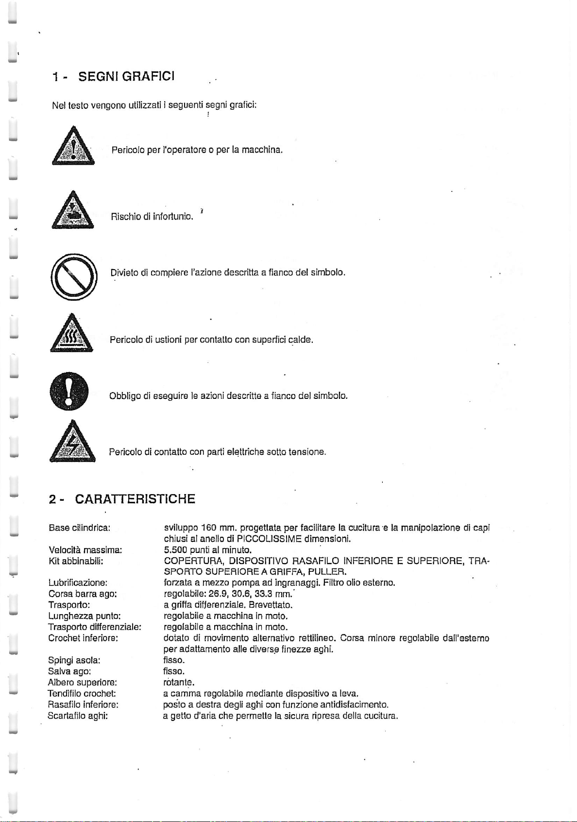
1 - SEGNIGRAFICI
2 - CARATTERISTICHE
3 - INSTALLAZIONE
4 - RIFORNIMENTO OLIO
5 - SMALTIMENTO OLIO
6 - GAMBIO OLIO
7 - MANUTENZIONE ,
INDICE
8 - FASATURA
9 - SOSTITUZIONE
10 - SOSTITUZIONE DELL'AGO •
11
-
POSIZIONAMENTO
12 - FASATURACROCHET INFERIORE
13 - FASATURACROCHET SUPERIORE
14 -
15 - MONTAGGIO E REGOLAZIONE GRIFFE
16 -
17
18
19 -
20 21 -
22 - REGOLAZIONE TRASPORTO SUPERIORE
23
REGOLAZIONE
REGOLAZIONE
- REGOLAZIONE LUNGHEZZA
- REGOLAZIONE
REGOLAZIONE
REGOLAZIONE
REGOLAZIONE
-
TRASPORTO
DELLA
CALIBRO
SALVA
RAPPORTO
TENSIONE
TENOIFILO
TENDIFILO
TENDIFILO
BARRA D'AGO
AGOE
MORSETTO
PIEDINOEREGOLAZIONE
AGHI
E SPINGIASOLA
TRASPORTO
PUNTO
CROCHET
CROCHETSUPERIORE
AGHIEPASSAFILI
INFERIOREACAMMA
PREMISTOFFA
DIFFERENZIALE
AGHI
Page 4
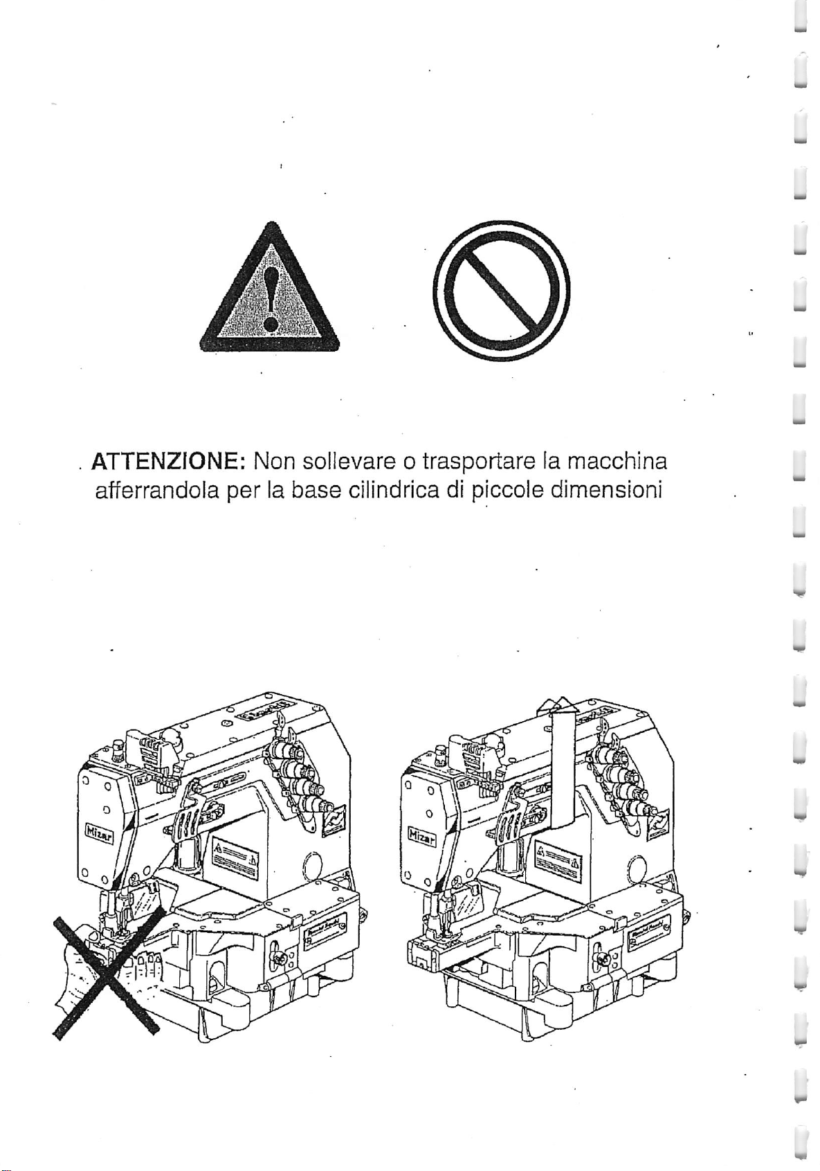
ATTENZiONE: Non sollevare o
trasportare
la
macchina
afferrandola
0 ^
ijf^
Qj
per
la
base
cilindrica di plccole dimensioni
0 r^ijUo,
ill
i
Page 5
1 -
SEGNI
GRAFICI
Neltesto vengono utilizzati i seguenti segni grafici:
Pericolo per I'operatore o per la macchina.
RischiodlInfortunio.
'
Divieto di compiere I'azione descrltta a flanco del simbolo.
Pericolo dl ustioni per contalto con superficl calde.
Obbligo di eseguire1eazioni descritte a fianco del simbolo.
Pericolodicontatto
con
parti
elettriche
sotto
tensions.
2-
CARATTERISTICHE
Base
cilindrica;
Velocjta
Kit
Lubrificaziane:
Corsa
Trasporto:
massima:
abbinabili:
barra
ago:
Lungtiezza punto:
Trasporto
Crochet
Spingi
Salva
differenzlale:
infericre:
asola:
ago;
Albero superiors:
Tendifilo
Rasafllo
crochet:
inferiore:
Scartafilo aghi:
svlluppo 160 mm. progettata
chiusia!aneliodlPICCOUSSIME
5.500
punti al
COPERTURA,
SPORTO
minute.
DISPOSITIVO
SUPERIORE
per
facilitare la cucitura-e la manlpolazione di capi
dimensioni.
RASAFILO
A GRIFFA, PULLER,
INFERIORE E
SUPERIORE,
TRA
forzata a mezzo pompa ad Ingranaggi. Flltro olio esterno.
regolabile: 26.9, 30.6,
33.3
mm.'
a griffa difterenziale. Brevettalo.
regolabile a
regolabile a
macchina
macchina
In moto.
In moto.
dotato di movimento alternativo rettilineo. Corsa minors regolabile daU'eslerno
per
adattamento
fisso.
fisso.
rotante.
a
camma
postoadestra
a
getto
d'aria
alle diverse finezze aghi.
regolabile medlante disposltlvo a leva,
degli aghi
che
con
funzione antidisfacimenlo.
permettelasicura
ripresa della cucitura.
Page 6

3-
INSTALLA2I0NE
IMPIANTO
L'impianto elettrico
senza
spina.
ELETTRICO
comprende
Gli
aflacciamenti consentiti alia rete elettrica sono quelil previsti dalle
Tinterruttore salvamotore (fig.3),11cavo dicotlegamenlo del motoreedun
norme
cavo
vigenti.IIcavo di
alimentazione (soloquellodicolore blu)e considerato a doppio Isolamentoe pertantopuo essere ullllzzato per
11
collegamento aereo, fissandolo opportunamente ad un montante verticale (es. portabobine).
NB.IIcavo
possano
doilperlcolodicontatti
In tutti 1
rimpianto elettrico ad una rete di
non
deve
essere
provocare
tip!
di allacciamento h Indispensabile collegare, medlanteilconduttore giallo-verde,
escoriazionl
infllato
occult!.
nel
tubo
portabobine
e tagli
alia
guainadiprotezione
messa
a terra ufflclalmente rlconosciuta
od in
eventual!
del
cavo
stesso,
(fig.
altri
2).
tub!
che
causan-
o
o
In ogni
terruttore
rispondere a! vaiore indlcato nella tabella affissa sulla
della tensione e deila potenza del motore utilizzato.
II
a far corrispondere i'indice a! vaiore richlesto.
case
veriflcare o far verificare da
salvamotore.IIvaiore di taratura (in Ampere) deii'interruttore salvamotore
partedipersohale
scatola
Per
verificare e regoiare la taratura togllere
competentelataratura
deii'interruttore
stesso
dell'ln-
deve
cor-
In funzione
coperchio deH'interruttore e ruotare I'apposita vita(oppure far scorrere I'indicedel cursore) sin
la
wM
Coliegamento
Attenzlone:
perchlo.
lampada
escludere
rallacciamento
Perdisporre di luce autonoma impiegare I'apparecchiatura
deii'interruttore
Entrata
Uscita regpiabilB = da 5 a12Volt,
SCHEMlDICOLLEGAMENTO
(ad
II
E =
esempio:
collegamento delle apparecchiature componenti le unit^ di cucitura o i sistemi di cucitura Rimoldl NecchI
devono rlspettare
a 5
fill
(neutro distrlbuito) e trifase, 380V a 4
caso
Nel
salvamotore.
125/160/220/240/380/415
SARA, RITA, SONIA,
gli
schemi di
di collegamento a llnea con neutro NON distribuito fig. 6 S necessario interporre tra interruttore
fig.
Volt
50/60
Hz.
220
VA.
PER
UNITA' DI
etc.)
CUCITURA
5 e 6 predispostt, rispettivamente,
fill
(neutro NON distribuito).
retedialimentazione
con
Rlmoldl
DOTATEDIAPPARECCHIATURE
019-90 da collegare a! morsettl d'entrata
peri
casi dilinee elettrlche trifase,
primaditogllere11co-
MONOFASE
SBOV
salvamotore ed apparecchlatura monofase un trasformatore monofase omologato per tension! di ingresso dl
380+415V
Plazzamento
Le
teste
seguenti caratterlstiche:
• tavoladilegno in pannello compensate
• piedini regoiabili
•
capacita
apparecchiature)
ed
uscita
220+240V
Rimoldl possono
per
assicumrne
200VAorichiedereIItrasformatore
essere
montate, nella maggior
la stablllta
di sopportare in mode stabile un
spessore
peso
Rimoldl
parte
del casi,subancall comuni, purchd abblano le
simbolo
40 mm
di almeno 200 Kg. (testa
P910054-0.
plO
motore,
pID
eventuali
Page 7
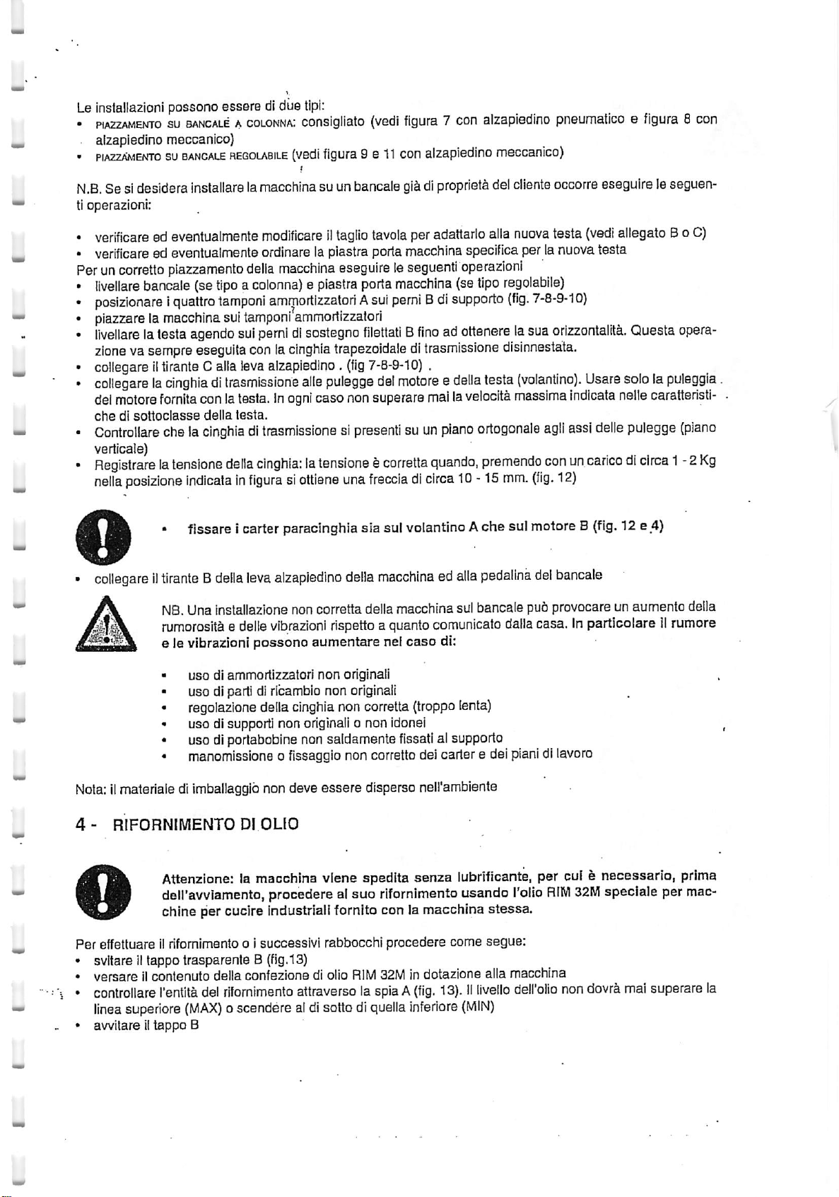
Le
installazioni
•
P1A22AMENT0suBANCALEAcoLONNAi
. alzapledino meccanico)
"
piAzzAMEisrrosuBANCALE
N.B,
Se si desidera
ti operazioni:
•
verificare
• verificare ed eventualmente ordinare la piastra porla macchina specifica per la nuova testa
Perun
corretto
•
livellare
•
posizionareiquattro
• piazzare lamacchina sui
•
livellare
zlonevasempre
• collegareiltirante
•
collegarelacinghiadltrasmissione
del
motore
chedisottoclasse
•
Controllare
vertical e)
•
Registrarelatensione
nella
possono essere dldue
installarelamacchina
ed eventualmente
piazzamento
bancale
latesta
posizione
(se
agendo
eseguita
Calia
fornlta
conlatesta,inogni
chela
cinghiadltrasmissionesipresent!suun
indicatainflgurasiottiene
tipi:
coRsigliato
HEGOLABiLE
della
tipoacolonna)apiastra
tamponi
tamponi
sul
conlacinghia
leva
(vedl
flQura
t
su unbancale
modificare11tagllo
macchina
ammortizzatoriAsut
ammortizzatori
pernidisostagno
alzapiedino.
aile
caso
della
testa.
della
cinghia:
latensionetcorretta
(vsdl
flgura
7 con
9 611con
tavola
eseguire le
porta
filettatiBfinoadottenere
trapezoidaledltrasmissione
(fig
7-8-9-10)
pulegge
non
del
superara
alzapiedino
gl&dlproprisla
peradattarlo alia
seguenti
macchina
pern!Bdi
operazioni
(se
supporto
.
motoreedella
mailaveloclta
piano
quando,
una
frecciadicirca
10-15
alzapiodino
meccanico)
del
ciiente
nuova
tipo
regolabile)
(fig.
7-8-9-10)
lasua
disinnestata.
testa
(volantino).
masslma
ortogonale
premendo
mm.
(fig.
pneumaticoefigura
occorre
testa
orlzzontallta.
eseguireleseguen-
(vedi
Usare
indicata
agll
assi
delle
conuncaricodlcirca
12)
8 con
allegatoBo C)
Quesla
opera-
sololapuleggia
nelle
carattsristl-
pulegge
(piano
1-2
Kg
fissare I carter paraclnghia sla sul volantino Ache sul motore B
o
collegareiltiranteBdella
jf\
jSJilL
Nota:IImateriale di
4 -
RIFORNIMENTO
NB.
Una
rumorositbedelle
e le vibrazioni
uso
uso di parti dl ribambio non originali
regolazione
uso disupporti non
uso di portabobine non saidamente fissatial supporto
manomissione o fissaggio non corretto delcarter e del
Imbailaggfb
Attenzlone: la macchina viene spedlta
deiravviamento, procedere a!suo rlfornlmento usando rolio
chine per cucire industrial! fornito con la macchina stessa.
leva
alzapiedino
Installazione
non
vibrazioni
possono
di ammortizzatori
della
non deve
Dl
OLIO
aumentare nel
cinghia
originali
della
macchinaedalia
corretta
della
macchina
rispettoaquanto
non
originali
noncorretta
c non idonei
essere
disperse neirambiente
sul
comunicato
caso
di:
(troppo
senza
lenta)
lubrificante, per cuf e necessarlo, prima
pedallna
bancale
del
pub
dalla
plan!dllavoro
(fig.
12 e 4)
bancale
provocareunaumento
della
casa.Inparticolare11rumore
RIWI
32M
speclaie per
mac-
Per
effettuare il rifomimento o Isuccesslvi rabbocchi procedere come
• svitareIItappo trasparente B
• versareilcontenuto della confezione di olio
•
controllare
llnea
•
awitareIItappo
I'entita
superiore
del
(MAX)
B
rifomimento
(fig.13)
attraversolaspiaA(fig.
oscenderealdi
RIM
sottodi
32M
indotazione alia macchina
quella
inferiore
13).IIliveilo
segue:
(MIN)
deirollo
non
dovra
mai
superare
la
Page 8
/k
/ik\
ATTENZIONE:
sigtlato
sigliati o
mischiare
I'agglunta
usare
olidltlpo
sempre
diverso.
dl additivl
olio
macchlnaecomportanoladecadenza
t
Solo In sltuazlonl particolarl In altematlva airolio
seguenti tlpi;
5 -
SMALTIMENTO
AGIPOTE
MOBIL
TEXACO
32
PTE
LIGHT
REGAL
DELL'OLIO
OIL
32
USATO
RIM
L'usodioil
possono
RIM
32M
siaIncaso
provocareildanneggiamento
delta
garanzla.
32M
prescrltto dalla casa, b posslblle usare uno del
dt camblo che di
iubrlflcantidltipo
rabbocco.E'scon-
diversedaquelli
Irreparabile
con-
della
Smaltendo in mode non corretto rollo usato, si
creano
gravl probleml di inquinamento aD'yomo,
agll animall, alCambiente.
E'necessario quindlsmaltire rollousato seguendo ledirettiveImpartltedal D.P.R. n" 691 del 23/
3/62 e
cio^
attenendosi
alle
seguenti
istruzioni:
1)11lubrificanteTipo32Me unoliodlnaluratotalmente mineraie.pertantodopoI'usd,appartlene
alia categoria degii "GUI
L'ollo
2}
usato
3) Consegnare
Usatl".
NOTA Telefonandoal
6 -
deiroiio
CAMBIO
usatosututtoilterritorio
OLIO
deve
essere
l'ollo
usato ad unodelraccoglltori autorizzati del"Consorzio Obbligatorlo
numeroverde
MINERAL!
USATi RIGENERABILi"
raccolto Inidonel contenltori adibitiesclusivamente a
1678-63048b posslblle ottenere Informazioni
nazlonale.
• Togllere11tappo 0 che b avvltatosotto la bacinella e scaricare completamenta
•
Smontarelatesta
• Pulire ed asciugare con scrupolo la bacinella.
• RiavvltareIItappo C controliando che ['anelio ditenuta
sostltuirio.
• Rlmontare la bacinella sulla
caso
contrario
• Procedereal riempimento della macchlna con
rifomlmentodlolio.
7-
MANUTENZIONE
dalla
occorre
bacinella.
macchlna
sostitulria.
controliando
I'olio
sia
in perfstta efficienza; in
che
la guarnizione dl
RIM
32Msecondo la procedura descritta nel paragrafo
tenuta
rollo
caso
sia
questo
necessarie
(fig.
perl! ritiro
13).
contrario occorre
ancora
efficiente; in
scopo.
degll
Olil
ATTENZIONE
mm
PRIMADlEFFETTUARE
EDILMOTORE
SI
METTAINMOTO
PRIMADlRICONNETTERE
TUTTII
CARTERERIMONTATO
DALLE
IL
MANCATO
SCHI
LE
RETI
PREMENDO
PER
LE
OPERAZIONIDlMANUTENZIONE
ELETTRICAEPNEUMATICA
IL
LE
RETI
TUTTE
RISPETTO
PERSONE.
PEDALE
ELETTRICAEPNEUMATICA
Dl
LE
PROTEZIONI
Dl
QUESTE
AVVIO,
EVENTUALMENTE
NORMEDlSICURE2ZA
DISINSERIRE
ED
ASSICURARSl
CHELAMACCHINA
ASSICURARSl
RIMOSSl.
PUO
LE
APPARECCHIATURE
Dl
AVER
RICHIUSO
FAR
INSORGERE
NON
Rl-
Le operazloni di manutenzione perlodica da effettuare per mantenere la macchlna sempre Inperfetta efficienza
sono:
Page 9
Ogni
giorno,
Smontarelaplaccae
gli
organ!
dellamacchina
pulirelegiiffe
ralatlvj
ai trasportoed aliaformazlone del punto
nsi
Aprire11pianodilavoro'ediicarter iateraie
Controliare punta degll aghl.
ControllareIIlivello dell'olioedeventualmente
o
Ogni
mese.
Controllare I'usura della cinghla.
Controllare
Ogni3mesi.
Pulire ii
• svitare con cautelailcontenltore
svltare completamente iicontenltore
• estrarre con cautelaIIfiltro
sa
nel
• rimontareIIfiltroeawitare11contenltore A(fig. 15)
NO.
Qualora non si Impiegasse rollo
tidlana.
I'usura
filtro
foro
del
salva
ago.
dell'olio attenendosi alle seguenti istruzlonl (fig. 14):
Eventual!rabbocchi devono
mischlare
ma! oli di
^
filtro
olioA{flg.14)
(fig.
dell'olioB(fig.
RIM
32M
tipo
diverse.
16)
17),
Immergerlo
prowedere alia sua sostltuzione.
essere
fatticon lo
loro
ranghitogliendoIIpulviscolo
ribaltabili
e pulire le zone accesslbill.
rabboccare
ed attendereIIdeflusso
inbenzineo
stesso
petrolio,
tipo di oliocontenutonelia macchina. Non
prima
dell'olio
con un penneiloin
di Inlzlare
rattivita
nelserbatoio
Indi
sofflare
aria compres-
quo-
prima
tutti
di
Ogni6mesi
Sostltuire
dere
Dopo
Se la macchina deveessere lasciata
Prima di
ControllareIIlivello dell'olio ed
Azionarela macchina a bassa veloclta- 3000
zampilli sotto1!tappo trasparenle di rifornimento
8 -
Allentare
RimuovereIIcoperchio
(fig.
morto
RimontareaH'estremit^ inferiore deila barra ago la fascetta B.Awitare, senza bloccare, la viteE
docurache lastessa
Inbatluta aU'eslremita Inferiore della barra d'ago. Serrare la vlte Edella fascetta B.
DI
conseguenza si ottieneilvalore
Le macchine
F93 punto ornamenio 602-605 F91 punto ornamento 406-407 -
rolloepulireiifiltro
alia
sua
sostltuzione ogni 3 mesi
un
iungo
periodo
riprendere
,Controllareche tutteJe protezloni antinfortunlstiche siano a) loroposto e periettamente
FASATURA
la vlte E
I'attivita
Collegare la macchina alle reti elettrica e pneumatica
DELLA
(fig.
iateraieB(fig.
19)
dellafascetta barraagoe
superiore), come
capitiinbatluta verso
MIZAR
hanno la
(vedi
voce
Ogni3mesi).
di inattivita
ferma
esegulreleseguenti
eventualmente
BARRA
AGO
18) della fascetta B
19)svitando le
riposizionare
Indlcalo
sulla
tabella difasaturache corredalatesta. Serrarela
difasatura
seguente
corsa
corsa
corsa
= 33.2
= 33.2
NB.
Qualora
per un
Iungo
periodo
operazioni:
esegulreunrabbocco.
girla!mlnuto
(fig.
18).
viti
per una decina disecond! controilandoche
SfilareIImorsetto porta aghl e la fascetta B
che lo
nonsi impiegasse
occorre
coprirla
fissanoa!braccio
conla
macchina.
assialmente la barraago perottenereilvalore
I'alto.
InfiiareIImorsetto
"A":
disfanzafrapuntaago destro e pianodaiiaplacca ago.
barra d'ago;
aghi,
prestandp attenzione a
rollo
RIM
cuffiaIndotazione.
Allentare
vlte
X.
32M
difase
(fig.
posizionaric
prowB:
efficlenti
I'olio
(fig.
lavlteX
(ai
punto
1B)
aven-
18).
Page 10
9 -
S0STITU210NE
La macchina e statacampionata infabbrica con aghi appartenenti ai sistema Indicato sulla etichetta posta sulta
parte superloresinislradelbraccloe dellamedesimafinezza dl
SI raccomanda dl Implegare sempre lostesso sistema diaghi.
consultareleistruzionealcapitolo
Per procedere aliasostituzionedel
> togllere ilmorsetto ailentando la vite E della fascetta B
• mbntareilnuovo
barra
ago;
stringers
• montare giiaghi (vedi capitolo "sostituzione deirago")
• allentare la viteE e orientare ilmorsetto inmodo da centrarli rispettoal
posizlone quando le punte degllaghisono centrate rispetto al
• stringere la vite E. ,
CALIBRO
AGHIEWIORSETTO
"l^asatura
caiibro
crochet
aghi e
quindi
queiil
consegnaticomeaccessorio.
Nel
case
divariazione della finezza Impiegata
infariore".
del morsettoeseguire leseguenti operazioni:
(fig.
16)
morsettoassicurandosi che la parte superiors vada inbattutacon la parte
prowlsoriamente
la vite E
for!.
for!
delta placca ago: si ha la corretta
inferiore
delta
NB.La posizione
predisposta
Se
necessltasse
10-
SOSTITUZIONE D'ELUAGO
Ruotaremanualmenteilvoiantino
Pago
esostltuirloconiinuovo.
della
macchina.
Servendosi della pinza Indotazione, accertarsi che I'ago appoggi sul fondo
Awitare,senza eccederenet
I
plant
deltacruna
II-POSIZIONAMENTO
Si ha lacorretta
al
trasporto.
TenerepresentscheconIIpiedino
sul
piano vertlcaie, distanza A rlportata sullo
dal posizionamento Inbattuta del morsetto.
Una
regolazione della distanza di fase Avedi capitolo "fasatura della barra ago".
PRIMA Dl
CHELAMACCHINA
ESEGUIRE
QUESTA'OPERAZIONE
SIA
COMPLETAMENTE
portando iabarraagotuttaInalto
Tenerepresentsche
bloccaggio,
degli
aghi
devono
PIEDINOEREGOLAZIONE
posizlone
del
piedino
AilentandolaviteC(fig.
sollevato
laviteserra agoD,avendocuradlnonvarlare
essere
quando
21) che
I'Incavo
paralleli
alia
gli
aghipassano alcentre
bloccaitpiedino
dicirca4,5
mm
schema
SPEGNERE
FERMA.
(fig.
difase, vlene automaticamente
IL MOTORE ED
18).
Allentarelavite
passaggiocrochetdeveessere
foro.
traiettoria
delcrochet
PREMISTOFFA
aliabarra6
daiia
placcad'ago,i
dalle
(fig.
feritole
possibile
piattelli
24).
dello
effettuare11centragglo.
serraagoD,estrarre
rivolto
Porientamento
stesso ed b
delie
essereaperti.IncasononlofosseroallentareilgranoAespbstare diquantonecessario11bracclo
la
pressione
che11piedino
deve
esercitare
sul
tessuto,
awitareo
svitare,
secondo
necessity,IIpomolo
ASSICURARSl
verso
I'intemo
dagli
aghi.
allineato
tensioni
B.Per
devono
regolare
D.
12-
FASATURA
Per eseguire lafasatura del crochet
- Montare gli aghi
• Montareilportacrochet0 sull'asta cornando crochet Dstringendo leggermente ja viteE
II
• Ruotare
• Montare
E.
•
Veriflcare
la
quota
voiantino
II
crochetA
laquota B
B (fig. 23).
• RuotareIIvoiantino
(fig. 24).
Avvlcinareilcrochet dell'ago finoa sfiorare rinterno dello scaifo
sull'asta
• Stringere la vile F (fig24).
D.
CROCHET
fino
a portare I'asta porta crochet Dai punto mortodestro (versoIIvoiantino)
(fig.
22) mandando ilpiano diappoggioin battuta sul portacrochet0 e stringere lavite
(fig.
23)come da tabelladifase. Se necessario, allentarelaviteF
fino
a portare la punta delcrochet sullo scaifoincorrispondenzadeil'asse dell'ago G
INFERIORE
inferiore
procedere nelseguente modo
(fig.
22 e
23);
(fig.
24) facendo ruotare ilportacrochet C
fig.
22.
(fig.
23)e ripristinare
fig.
23.
Ui
Page 11
13-
FASATURA
inserire il gambo cilindrico del crochet nel fore del porta crochet E (fig. 32), posizlonandolo In altezza
ottenerela quotaHdel fogllodlfase,
con
I'anelio F
E.
la vlte C, facendo in modo
Controliare,coniifogllo
caso
Nel
non lo fossero effettuare ajcune reglstrazioni operando come sotto indicato;
a) quota "e"
< togliere
partlcolare E (fig.31)
spostandoiipemo
-
b)
quota
T (fig. 29):
- per
ottenereiaquotaTaiient^reiavlte
c) quota "g" (fig.30):
-
per
ottenere ia quota "g"aiientare iavite De la vlte 0
attenziona
del porta crochet.
CROCHET
SURERIORE
che
rappresentala dlstanza frapiano placca
che11suo
piano Inclinatocombaci col corrispondentedel porta crochet
ago
e fondo
crochet
difase aliegatoad ogni macchina, che le misure" e - f-g" corrispondano (fig.2B,2g,30).
(fig.
28)
per
van'are la corsa del crochet di copertura si prowedera come segue:
11
coperchio superiore del braccio, sbioccare11dado Be fare scorrereIIpemo A nella cava del
verso I'altosi diminulsce la corsa, al contrarlo, versoIIbasso, la si aumenta.
0 e
afflnchd
Taneiio
dlfermo F
ruotare
(fig.
32)colsuo pianoinciinato combacisempre colcorrispondente
sul
suo
pernoIiporta
(fig.
32) e ruotare ilcrochet sul suo gambo. Porre
crochet.
onde
Bloccare
N.B.-Quandosi
del crochet, § conslgllabile smontario; per fare ci6 si ailenter^ ia vite D (fig.32) e si sfllera dal porta crochet il
crochet. Quandosi richiederd la
verr^
automatlcamente
14-REGOLAZIONE
It
salvaago e io spingi asola sono di tipofisso. EssI costitulscono ungruppo formatoda tre pezzi:IisupportoA,
ii
saiva
aghi C e lo spingi
Salva
ago
Montare dapprima iisupporto Asuila
Con la
ia vite D in modo
deli'ago F.
Quando la punta del crochet si trova suli'asse deli'ago F flg.25/2 tra i'ago ed ilpunto E deve risultare una
quota
Bloccare
Spingi
asola-
presentasse
barra
ago al punto morto Inferiors allinearejisalva
Questa
0,0
doeiisalva
ie viti B fig.
lanecessitadlcucire
sua
funzione si rimonter^ lispettando quanto detto per iafasatura; e owlo
ragglunta la
SALVA
asola
cheIipunto E deiia fig. 25/1 deve corrispondere con la parte Inferiore delta cruna G
condizione permette iaformazione dell'asola del
ago deve
25/3.
sua
fase
AGHfESPINGI
Lvedi (fig.25/3)
base
essere
tangente all'ago F fig. 25/2
senza
fiio
dicopertura supenore, per evitareIImotoosciliatorlo
ASOLA
cllindrlca awltando ie
ago
agliaghi e posizionarlo in altezzaallentando
due
vitiB
senza
fllo
dell'ago durante la
bloccarie. (fig.25/3)
sua
risaiita.
che
Portare gliaghi al punto morto inferiorefig26/1. AiientarefavlteS fig.26/1 ed allineare lospingi asola L ai
due aghi estremi. Quando la punta dell crochet si trova suli'asse dell'ago F lo spingi asola deve
regolato anche inaltezza Inmodo che ia
delta cruna deil'ago F (vedlfig.
quota R fig.26/1.
Bloccarelavite
P.
26/2).
sua
parte superiore debba corrispondere con laparte superiore
Con ia vite P avvicinare lo spingi asola agli aghi flno ad ottenere la
essere
15-MONTAGGIOEREGOLAZIONE
.• Montare le griffesuite rispetth/e slitte come iilustrato In figura(
-
II
centraggio delle griffenelle feritoiedella piacca indirezione ortogonale al trasporto
mente. ilcentraggio nella direzione del trasporto h stato eseguito in fabbrica.
Ruotare
• Le griffe devono
approssimativaoccorre tener
ailo
•
Per
mente
H'voiantino
spessore
effettuare le eventuaii correzioni della posizione in altezza deiie griffeaiientare le vitiA e B rispettiva-
delta griffadifferenziale e della griffa del punto.
e portare ie
sporgere
del denti (quota 0 fig. 27)
griffe
dalia placca delta quantity Indicate suila documentazione tecnica di
presents
GRIPPE
(fig.
27)
al punto mortosuperiore.
che
ie griffedevonosporgere dal piano placca per
awlene
una
automatlca
fase.
In via
quantity part
Page 12
16-
REGOLAZIONE
II
masslmo edIIminlmo rapporto differenzlale
RAPPQRTO
TRASPORTO
sono
impostati daila fabbrica Infunzione della sottoclasse consi-
derandoIIsettore marceologico cul la sottoclasse &destinata.
rapporto differenzlale allentando11pomolo L
dimlnulsce) o verso11basso
zlale e 1:1,
zlale masslmo otteniblle b 1.6+1, mentre quello minlmob 0.6+1.
La regolazione trasporto differenzlale pub
doelagriffa
(il
rapportodifferenzlale aumenta).
differenzlaleesegue la
(fig.
essere
36), spostando I'lndice verso
stessa
corsa dl quelladel punto.IIvaloredel rapporto differen
esegulta
anche
DIFFERENZIALE
Nell'amblto
L'Indlce
a macchina Inmoto.
di tall
centrale
Indica
limiti
I'alto
(II
cheIIrapporto
b posslblle variare
rapporto differenzlale
differen
11
17-REGOLAZIONE
La lungiiezza punto pub
• Allentare llpomoloA
LUNGHEZZA
essere
varlala spostando verticalmenteIIpomolo A(fig.35).
PUNTO
• Muovereilpomolo verso I'altoper diminuire la lunghezza del punto, verso11basso per aumentaria
• Stringere ilpomoloA
La regolazione della lunghezza punto pub
18
- REGOLAZIONE TENSIONE (fig.
II
filo
vienepremutofraIduedischiAdellatensione, dallamollasituataneirinternodelpomoloB;quindi, peravere
essere
esegulta
36)
anche
a macchina Inmoto.
la giustaformazlonedel punto e necessario regolare la pressione deifamollaawitando o svltandoIIpomoloB
della tensione
stessa.
Nella magglor parte del
casi
la tensione del
fllo
crochet Inferloreviene
tenuta
lenta e la
regolazione si effettua mediante tenslonclna Happjicata sulla piastra camme tendlfllo fig. 34.
19-REGOLAZIONE
II
tendlfllo a
• lunghezza punto
•
spessore
•
elastlcHb
L.a
regolazione della cammatendlfllo pub awenlredaH'estemo allentandoIIpomoloG
camma
del
tessuto
del
filati
ilpomolo verso I'altosi ottiene un Incremento del recupero del
utilizzano
punt!
corti,
ottiene un minorrecupero del
grosso
Aprendo11carter frontale H(fig.36) e posslblle effettuare
camma sul
macchina si ottiene un ritardo nella fase dl rilascio del
senso
Questa
ATTENZIONE:
conlaceva
Idue
per
spessore,
si ottiene un anticipo della fase di rilascio del
operazione pub
dIschI
eseguire una eventuate centratura allentare le
filati
fllo
del cfocheL Allentando la vite B
neU'eseguIre
L(fig. 34) deH'astina
dellacamma
assialmente la camma sull'alberino sporgente dal basamento e fissaria,
ottenere le condizionl dl cul sopra.
Circa la posizione clrconferenziale del dischi,
destra devono tendere il
TENDIFILO
del
crochet
tessuti
rigidl.
essere
tendlflloE(fig.
filo.
deve
essere
CROCHET
regolato infunzione di:
INFERIORE
A CAMWIA
(fig.34e 36). Spostando
fllo
trasclnato dalcrochet necessario quando si
leggeriofilati
fllo
del crochet necessario quando si utilizzano punti
necessaria
questa
passafilo
mqlto
elastlcl.Ajcontrario
spostandoIIpomolo
lunghl,
una
ulterlore regolazione della fase di Intervento della
(fig.
34) e spostando I'astlna passafllo C
fllodaparte della camma, spostando la leva nell'altro
filo.
nel
caso
di trasformazione del calibro aghl.
operazione
asslcurarsi
C (fig. 34).
che
ifori del passafilo F(fig. 34)
34)debbano essere perfettamentecentratl con i'astlna 0
viti
tenere
Dsul mozzo Adella camma
quindi,
presente
che, quandoIIcrochet inlzla la
(fig.
33 e 34), fare scorrere
nellacorretta posizione onde
versoIIbasso si
tessutl.pesanti o dl
(fig.
34) verso la
siano
(fig.
sua
corsa
AccertarsI della corretta regolazione effettuando alcune prove di cucltura.
alllneab*
34).
verso
20-REGOLAZIONE
Un'astina
tirafllo
Amontata sull'anello B governa il
Lecondizionl difase
II
file
intensione. L'azione dell'astina Adeve cessare quando la punta dell'ago sinlstro b ben penetrata nel
triangolo formatodal
TENDIFILO
CROCHET
fllo
ottimali
si hanno quando, concrochetsuperlore spostato tuttoversoslnlstra,i'astlna Atiene
filo
dl copertura come rappresentatoInfig.
SUPERIORS
crochet dlcopertura
38.
(fig.
37).
L'astinasl pub regolareassialmente allentandolavlte0 ed angolarmente allentandole
l.acamma G
orlentata
(fig.
38)concorre aliadisposizionedel
secondolanecessita.
filo
a mbdi triangolo. Pubessere regolataverticalmenteed
vlllD(fig.
37).
Ui
Page 13
21 - REGOLAZIONE TENDIFILO AGHl E PASSAFILIAGHI
II
tendifilo
0
diminuendo
II
tuttosiotllene
della macchlna. '
Lavariazionedella corsa del
facendolo scorrere
spostandolo
IntermlttenteF(fig.
lasuacorsa)eper
agendoin
verso
versodestra,
36)acorsa
regolabile
variarelosvlluppo
sinergismo
tirafiloF(fig.
sinistra si aumenta ia
con11passafilo
36),
Invece,siotterranno
serveperottenere
del
cappi
format!
dai
MediltendifiloNmontati
si ottiene allentando le
sua
corsa
e quindi si otterranno cucilure
cuciture
piD
rigide.
cucltura
fill
pIDomeno
degli
aghi.
sul
viti
E e spostandoiitendifilo
elastiche
asecondadel
fronte
del
(aumentando
tlpodifilafo.
braccio
pi£j
superiors
stesso,
eiasliche;
22-REGOLAZIONE
Fasatura
RuolareIIvolanlino
coincidere !e linee di
Fasatura
eccentrico
fino
eccentrico
AllentareigraniAdeU'eccentricoB,far
graniAdeU'eccentrico.
Fasatura altezza
Rimuovereilcarteriaterale,allentare la
Serrarelavite
Fasatura poslzlone "0" regolazione trasporto superiore
Rimuovereilcarter
(Fig.
42).
AllentarelaviteB(Fig.*43)
Regolazione poslzione slitta porta griffa superiore
Conilpledino
abbassandole, successlvamenle allentarele due
la
vile
Bcome indicato in
ago.
Posizionare
23-TRASPORTO
La
massa
delia macchlnae circa 45 Kg.
guida
A.
posteriore.
appogglato
labarra
TRASPORTO
trasporto
a portarelabarra ago a!punto
fede
del sollevamento griffa
(fig. 39)
deU'eccentricoB e dell'albero C. Serrare i grani AdeU'eccentrico.
SUPERIORE
morto
superiors
coincidereleilneedifede
barra premistoffa (fig. 41)
viteAfino
a portare laguida Ba una
Allentareilpomolodiregolazione
finoaraggiungerelaquotadimm.
sulla
piacca
ago
allentareiedue
viti
Ee D(Rg. 43). MontareilcalibroA
Fig.
44.
Ruotareilvolantino
premistoffa
nei
fermi0(Fig.
fino.
44)
inferiore.
(fig. 40)
AllentareIgran!AdeU'eccentricoB,far
deU'eccentricoBedel
dalle
trasporto
viti
Ae B
a raggiungereiipunto
del
calibro.
superioreaporlarlo
4,5
(Rg.
(Fig.
27)
che
Serrareledue
voianoC.Serrare
due quote indicate
42),
SerrarelaviteB(Fig.
fissano
morto
ledue
(simb.
C.2059-00)con
superioredeiia barra
viti
Ee D
Fig.
nel
punto
griffe
43.
1
in.figura.
"0"
43).
inferior!
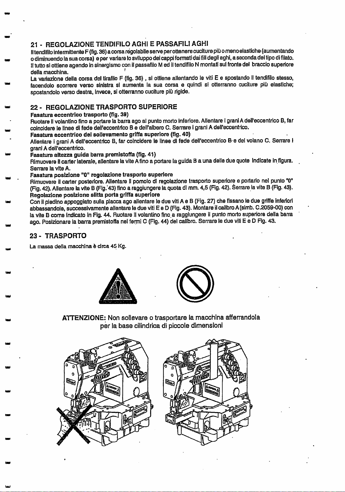
ATTENZIONE:
per la base cilindrica di piccole dimensioni
Non
soilevare o trasportare lamacchlna afferrandola
Page 14
WARNINGS
For genera! warnings on
the
subject of safety,
see
the
INSTRUCTION BOOKLET.
The
installation
and
adjustmentaswellasmaintenance operations shown in this booklet must only be carried out by specialist
technical
WARNING
BEFORE CARRYING OUT MAINTENANCE OPERATIONS, DISCONNECT THE EQUIPMENT AND MOTOR
FROM THE MAIN ELECTRIC AND PNEUMATIC CIRCUITS, AND MAKE
START
BEFORE
COVERS
HAS
NONCOMPLIANCE
CONDITIONS
CF Italia srI
defects in material or workmanship for
the
During
as
by
staff.
BEEN
end
the
them
WHEN
user
the
"Seller"),
THE
PEDALISPUSHED.
RECONNECTING TO THE MAIN ELECTRIC AND PNEUMATIC CIRCUITS, MAKE
HAVE
BEEN
CLOSED
REPLACED.
WITH
THESE
OF
GUARANTEE
guarantees
that all Rimoldi machines (hereafter definedas"the products")
(client).
guarantee period,
will
repair or replace
on behalf of CF Italia srI free of
AGAIN
SAFETY
RIM,
AND
ALL
PROTECTION
one
RULES
shift
per
MAY
day
for twelve months from
the AGENT or the RETAILER of
any
detective parts of the products covered by this
charge.
The
repaired or replaced
PUT
WHICH
PEOPLE
the
SURE
THE MACHINE DOES NOT
SURE
ALL
MAY
HAVE
BEEN
REMOVED
AT
RISK.
will
be free from
the
date
the invoice is
issued
Rimoldi machine (hereafter defined
parts
are
guarantee
only
guaranteed
and
for
sold
the
remaining period of the product guarantee. Any maintenance operations and repairs earned out during the
guarantee
period do not modify
the
expiry
dateofthe
guarantee
itself.
to
The guarantee operations
case,
the
client
must
become
property of CF Italia
Final decisions regarding
takenbytheCFItalia srI Quality
This guarantee
or inexpert
supply
systems
not
cover
are
wom
plates,
This
presser
guarantee
requests
use
of a Rimoldi machine,
product itself
does
noi cover breakdowns
useofthe
(electric and pneumatic),
damage
due
to electronic parts
to normal
foots, knives, loopers, etc.
only
are
excluded, including
are
also
implicit,including therein
This is
the
unique
and
and CF Italia srI, relating to
itonbehalfofthe
In
the
case
sellerorCF
of dispute regarding
are
carried out on the client's premises, or, if necessary, at
assume
all transport
costs
srI.
the
validity of
the
guarantee
Management.
due
to normal wear, unauthorized operations or modification,improper
product, lack of, incorrect or insufficient maintenance and/or lubrication, inadeguate
use
of non-original
useofthe
ensures
the
caused
machine
client for
those
related to
by natural atmospheric
are
the
repair
evenifduetothe
excluded. This
any
guarantee
complete
the
Italia
guarantee
that
the
agreement
which
guarantee. Noemployee or organization of
srI.
the
contents, limits of application
guarantee, the Italian version of these regulations
provided
out
of courtesy.
and
risks. Any replaced parts removed from
service
not replaced under guarantee,
and
boss
of production or
breakdown of
replaces
requests
spare
and/or technical methods involved
parts and/or accessories and, finally,it
events.
Therefore,
suchasneedles, feed dogs,
replacement of defective parts. All
any
the
other
damage
machine
guarantee
to things or people
itself.
Requests
or condition, either explicit
product is suitable for particular purposes.
regulates
will
apply, since translations into other languages
the
relationship
between
the
seller is authorized to modify
and
anything
the
else
the
sellers. In this
the
components
other
claims
duetothe
to replace
client,
the
concerning
product
are
does
which
and
the
seller,
the
are
only
or
The
CF
in
Italia
this
srI
brochure.
reserves
competent
the right to modifyorvary, for technicai or commerciai reasons, the information printed
law court is Busto Arsizio, Italy.
Page 15

CONTENTS
1 -
2 3 4 -
5 6 -
GRAPHIC
FEATURES
INSTALLATION
FILLING
DISPOSAL
OIL
CHANGE
SYMBOLS
WITH
OF
7 - MAINTENANCE
8 -
9 -
10
PHASING
REPLACING
-
SUBSTITUTING
THE
11 - POSITIONING
.REGULATOR
12
-
13
14
15
16
PHASING
r
PHASING
ADJUSTING
-
ASSEMBLING
-
ADJUSTING
THE
THE
THE
THE
OIL
USED
•,
NEEDLE
THE
NEEDLE
THE
NEEDLE
THE
PRESSER-FOOT
LOWER
UPPER
NEEDLE
AND
ADJUSTING
DIFFERENTIAL
OIL
BAR
LOOPER
LOOPER
GAUGE
GUARD
THE
AND
AND
FEED
AND
FRONT
FEED
RATIO
CLAMP
SETTING
DOGS
PRESSER
NEEDLE
SPRING
GUARD
17
18
19
20
21 -
22
23
-
ADJUSTING
-
ADJUSTING
-
ADJUSTING
-
UPPER
ADJUSTING
NEEDLE
-
TOP
-
TRANSPORT
LOOPER
FEED
THE
STITCH
THE
TENSION
THE
LOWER
THREAD
NEEDLE
ADJUSTMENT
THREAD
LENGTH
LOOPER
THREAD
TENSIONING
TAKE-UP
TENSIONING
ADJUSTMENT
AND
THREAD
CAM
GUIDE
OF
THE
Page 16

Page 17

1-
The
GRAPHIC
following
SYMBOLS
.
graphic symbols are used Inthe text:
Injury
of
to the operator or damage to the machine.
Riskofan
Action
Risk of burns through contact with hot
Action
accident
described
descnbed
^
beside
the symbol prohibited.
beside the symbol obligatory.
Risk of contact with live electrical parts.
surfaces.
2-
FEATURES
Cyiihdrical
Maximum
Compatible
Lubrication:
Needle
Feed:
Length
Differential
base
speed
bar
of stitch
Lower looper:
Front
needle
Needle
guard:
Upper shaft:
Looper
Lower
Needle
thread
thread
thread
Kits:
stroke
feed:
guard:
cutter
take-up
wiper:
160 mm long, designed to facilitate the sewing
garments
5,500
TOP COVER,
forced by
adjustable: 26.9, 30.6,
differential
closed
into a ring.
stitchesaminute.
LOWERANDUPPERTHREAD
meansofgear
feed
dog.
Patented.
pump. External oil filter.
33.3
mm
adjustable withthe machlne'operating
adjustable with the
withstraightalternate motion. Minimum
to
the
fineness
fixed
fixed
rotary
with
a cam adjusted by a lever mechanism
located to the right of the
with
an airjet that ensures reliable sewing resumption.
of
machine
the
needle.
operating
needles
stroke
and preventing the
and
handling of EXTRA
CUTTER,TOPFEED, PULLER.
adjustable from outside to
seam
unravelling
SMALL
adapt
Page 18

3-
INSTALLATION
ELECTRIC
The
electric
The allowed connections to the electric grid
The powercable (theblue one only)Isconsideredto be double Insulated, and therefore can be used foroverhead
connectionsbyfixing
SYSTEM
system
includes the motor cutout switch
are
those laid down by the laws In force.
it to a suitable vertical column (e.g.
N.B.-The
cable
must
notbethreaded
(fig.
3),
tubes whichcodidcause abrasions and cuts inthe
leadtothe
With
acknowledged
riskofhidden
contacts.
everytype ofconnection, itis necessary toconnect the electricsystem toan officially
earth using the yellow-green conductor
the
motor connecting cable and a cable without plug.
the
bobbin holder).
through
the
bobbin
wire
(fig.
holder
tubeorany
protectingsheath, whichmay
2),
other
o
Always, either
competent
to the value shown on the table
power of the motor used. Inorder to check
and turn the special screw (or move the cursorindex)
value.
check
staff. The value of the motor cutout switch setting
the
settingofthe
attachedtothe
motor
and
cutout
switch box itself, according to the voltage
adjust the setting, remove the switch cover,
switch
until
the index points to
or have It
(in
amperes) must be equal
checked
the
required
by
and
Warning:
Lamp
Connection
To
provide
motor
Input E = 125/160/220/240/380/415 Volt50/60 Hz.
Adjustable output U= from 5 to 12 Volt
CONNECTION DIAGRAMS FOR SEWING UNITS FITTED WITHSINGLE-PHASE DEVICES (for
SARA, RITA, SONIA,
The
comply
phase
In
the
autonomous
cut-out.
etc.)
conneclions of the devices which make up the
with
the diagramsInfigures
and
four-wire
case
of connection to lines with NON-distrlbuted neutral (fig. B), it Is
380 V(NGN-distributed neutral) electriclines.respectively.
single-phase transformer for
motor cut-out
Setting
Rimoldi
characteristics:
- 40 mm thick plywood panel table
- adjustable feet to
-
ability
and
single-phase devices, or
heads
can
be fitted to common
ensure
to support a weight of ^ least 200 kg stably, (head plus motor plus any devices)
disconnect
lighting
Input
stability
from
the
mains
use the
Rimoldi
220
5 and 6 set out
VA
019-90
for
before
apparatusto be connected
Rimoldi
the cases of
removing
the
cover.
with
Necchi sewing units or sewing systems must
five-wire
(distributed
necessary
voltages of380-415V and outputvoltages of220-240V
request
stands
Rimolditransformer n. P910054-0.
Inthe majority of
cases,
provided the
the
Input
clampsofthe
neutral)
to place an approved
200VA
stands
have the following
example:
380 Vthree-
between the
Page 19

The installations may be either of the
INSTALLATiONONCOLUMN
.
figure 8 with a mechanical presser
•
INSTALLATIONONADJUSTABLE
STAND:
following
foot
STAND:
types:
recommended (see figure 7
lift)
(see figure 9
with
a pneumatic presser foot
and11with mechanicai presserfoot
lift)
lift
and
N.B.Ifyou wantto
carried
•
•
To
• level the stand
• position the four rubber pads Aon the support pins B (figs. 7-8-9-10)
• place the machine on the rubber pads
• level
• Connect tie-rod C to
• Connect the drive belt to the motorand head pulleys(handwheel).Onlyuse the motorpulleysupplied with
• connect the tiered B of the machine's presser fool
out:
check
and, ifnecessary, modifythe table cut to
check
and, ifnecessary, order the specific machine holding plate for the new
ensure
carried out with the trapezoidal drive belt disconnected.
the head, in any
Check that the drive belt is on a plane at
Adjust
of
the
about
that
thie
1-2 kg In
instail
the machineona stand
the
machineisset
(if
column type) and the machine holdingplate
head by turning the threaded support pins Buntilit Is horizontal.This operation should always
the
case,
never exceed the maximum
belt
tension:
Fix
the
the
position
the
up correctly,
presser
foot
tensionIscorrect
shownInthe
belt
guards
lift
bothatthe
belonging
adapt
proceedasfollows:
lever
(fig.
7-8-9-10)
speed
.right
angles 1othe pulleyaxes (vertical plane).
whenacamberofabout
figure 12.
handwheel
lift
to the customer, the
it to
the
new
head
(see annex B or
(If
adjustable type)
shown in the characterisllcs ofthe head subclass.
10-15mmis
and
the
motor
and the small pedal ofthe stand.
lollowing
head
procedure mustbe
0)
createdbyplacingaload
B (fig. 12
and
4)
be
iGV
NOTE;
4-
The
packing
FILLING
O
In
ordertofill
• Unscrew transparent
•
PourInthe
• Check the amount pouredInthrough sight glass A
•
(MAX)
Screw
or fall below the lower
cap
Incorrect
than
stated
• Non-original
• Non-original
• The belt is not adjusted correctly (too slack).
• Non-original or unsuitable supports
• Bobbin holders which
•
Guards
material
WITH
Warning:
it is
necessary
provided
Itor later
contents
B back on.
installationofthe
by the manufacturer. In particular,
rubber
pads
spare
parts
and work
OIL
the
machine
wrth
top
it up,
cap
B (fig. 13).
of the RIM 32M oiltin supplied with the machine.
surface
shouldbedisposedofproperly
Is
supplied
to fill it
the
proceedasfollows:
one
using
machine
(MIN).
machineonthe
are
used.
are
used.
are
not firmlyfixed to
have
bee/i
without
the
special
Itself.
stand
can
noise
are
used.
the
support
tampered
with or not fixed correctly.
lubricant,
oil
for
Industrial
(fig.
13).
The
oillevel must never exceed the upper line
leadtomore
and
vibrations
are
therefore,
noise
can
increase
used.
before
starting
sewing
machines-RIM
. .
and
vibrations
when:
the
machine,
32M •
Page 20

Ak
WARNING:
is
not
than
damage
always
use
RIM
advisable to mix oils of different
the
oil
recommendedorthe
and
the
forfeitureofthe
32M
both
when
types.
additionofadditives
guarantee.
the
oilischanged
The
use
and
whenItis
topped
of lubricating oils of a different
can
leadtoIrreparable
machine
up.
type
It
Onlyin special siluations,Itis possible to use one of the
oil
recommendedbythe
AGIPOTE32
MOBIL
TEXACO
DISPOSAL
Incorrect disposal of used
environment. Itis therefore
below:
1)
manufacturer:
DIE
LIGHT
REGAL
OF
USED
OIL
32
OIL
oil
causes serious polluticn problems for
necessarytodispose
RIM
32M lubrication oil is totally mineral, therefore after
RECLAIMABLE
USED
MINERAL
2) The used oil must be collected in a suitable container used exclusivelyfor this purpose.
3)
The
oil should be delivered to a legally
6-
OIL
CHANGE
- Remove
-
Remove
- Clean
Screw
-
- Fit
the
cap
the
and
cap
oil
C which Is
oil
can
dry the oil
C back on
can
back on the machine
screwed
from
can
and
the
head.
carefully.
make sure
on underthe oil
seal
ring B
and
check
the
seals
replaced.
-
Fill
the machine with
RIM
32Moilaccording tothe procedure described under
fQliowing
types ofoilas an allernativeto the
man",
of the oilby carefully
use
OILS"
can
authorized
and
allow the oil to flow out completely
body.
perfectly; Ifthis is not the
sealing Is still effective; if this is not the
fQliowing
it is categorized
case,
FILLING
RIM
32M
animals, and the
the
instructions
among
{fig.
it mustbereplaced.
case,
WITH
the"
13).
it must be
OIL.
7-
MAINTENANCE
BEFORE
FROM
START
BEFORE
COVERS
BEEN
The
order
CARRYING
THE
MAIN
WHEN
RECONNECTING
HAVE
REPLACED.
NONCOMPLIANCE
periodic maintenance
are:
OUT
ELECTRIC
THE
PEDALISPUSHED.
BEEN
CLOSED
operations
WARNING
MAINTENANCE
AND PNEUMATIC CIRCUITS, AND MAKE
TO
THE
AGAIN
WITH
to be carriedout Inorderto
OPERATIONS,
MAIN
ELECTRIC
AND
THESE
ALL
PROTECTION
SAFETY
DiSCONNECTTHE
AND
PNEUMATIC
WHICH
RULES
MAY
keep
EQUIPMENT
SURE
THE
MACHINE
CIRCUITS,
MAY
HAVE
BEEN
PUT
PEOPLE
the
machineconstantly inperfectworking
AT
MAKE
REMOVED
RISK.
AND
DOES
SURE
MOTOR
NOT
ALL
HAS
Page 21

Every
day.
o
Each
month.
-
Check
the
- Check the
Every
three
months.
- Clean the
-
Unscrew
unscrewing
then
- Replacethe
If
RIM
oil
blow
32M oil is not used, replace it. •
Remove
involvedinfeed and
Open
of
Checkthe oil level and, if necessary, top up before starting
wearofthe
wear
oil
filterbyfollowing
filter
the
the
filter
Any
Never
theplateand
the
swing-out
the
needles.
belt.
of the
needle
containerA(fig.
container
hole with
andscrewback container A
(fig.
compressed
clean
forming
wdrk
guard.
the instructions
13)
16).
Extract
air.
tappingupmustbedone
mix
oilsofdifferent
the dogsintheir
the stitch witha paintbrush.
table
and
side
below
carefully
oil
filterB(fig.
with
types.
and
(fig.
the
cover
(fig.
wait
15)
same
rows,
and
14):
for
the
17)
typeofoil
wiping
clean
oiltoflow
carefully
containedinthe
all
the
and
the dustoff
accessible
the
back,into
Immerse
all
themachine's parts
areas.
Check
daily activity.
thetank
before
itin
petrolorparaffin
machine.
the
point
completely
and
Every
six
months
-
Replace
three
After a
If
the machineis notused
Before startingto
Check
Run
fijiing
B-.
Loosen
Remove
19)onthe
centre),asindicatedinthe
Reassemble
positionitso
bottom end of the needle bar. Tighten the
Consequently,
needle
The MI2ARmachines have the following
F93
F91
the
months.
long
period
the
oil level and, If
the
machineatlow
cap.
PHASING
the
screwE(fig.
theside
needle
the
thatitstrikes
plate.
interlock
interbck
stitch
stitch
oil
and
clean
the
filter
(see
without
use11again, carry out
Checkthat
Connect the machine to the main electric
THE
coverB(fig.
bar
clip
Bonthe
the
phasing
602-605-stroke=33.2
406-407-stroke=33.2
use
foralong
necessary,
all
the accident-prevention guards are in placeand perfectly operative.
speed
NEEDLE
18)
onthe
clip
and
phasing
upwards.
value
time,Itis necessary to coverItwith
top itup.
(«3000
rpm)
BAR
clipB(fig.
19)
loosening
reposition
table
bottom
endofthe
Insert
"A"isobtained:
"Every
three
months").
the
following operations:
for
about
10seconds
18).
Pull
the
the
needle
that
comes
the
screw
needle
•
screws
needle
needle
the
that
bar
with
bar.
clamp,
E on the clip B.
distance
bar stroke:
N.B.IfRIM
and
pneumatic circuits.
and
check
out
the
needle
fixIttothe
axialiytoobtain
the
head.
Tighten
Tighten
the
taking
between
32M
oilisnot
the cover
thai
oil
holding
machine
screwEslightly
the
phase
the
clamp
arm.
screw
used,
provided.
flows
under
and
Loosen
value
X.
(fig.
caretopositionitso
the
right
needle
point
replaceItevery
the
transparent
the
clipB(fig.
the
screwX(fig.
(at
the
upper
16),
taking
thatItstrikes
and
surfaceofthe
dead
care
18).
to
the
Page 22

9 -
REPLACING
THE
NEEDLE
GAUGE
AND
CLAMP
The machinewas fittedat the factory withneedles belongingto the system indicated on the label on the top left
part of
the
arm and of the
We recommend you always use the
in
the
"Phasing the LowerLooper" section.
To proceed to replace
• reihove the
clampbyloosening
• assemble the new clamp
screw
E provisionally
the
same
finenessasthose
same
needle
gauge
the screw E on the
making
deliveredasan accessory.
system
and
of needles. Ifthe fineness used is varied,
see
then the clamp, perform the following operations;
clipB(fig.
18)
the
instructions
sure that the top part strikes the lowerpart ofthe needle bar; tightenthe
• assemble the needles (see the "Replacing the Needle"section)
• loosen the screw E and turn the clamp so
as
to align the needles with the holes in the needle plate: itIs
correctly positioned when the points of the needles are straight in linewiththe holes.
• tighten
N.B.
by
positioning
Ifthe
10-
the
screw
The
position on
the
phase
distance Ahas to be regulated,
SUBSTITUTING
E.
the
vertical plane,
ciamptostrike.
THE
NEEDLE
distance
see
Aindicated on
the
the "Phasing the Needle Bar"section.
phase
diagram, is automatically
set
SWITCH
CHINEISABSOLUTELY
Turn the handwheei manually to bring the needle bar rightto the top
OFF
THE
MOTOR AND
ENSURE,
STATIONARY.
BY
PRESSING
(fig.
18),
THE
PEDAL, THAT
THE
MA
Loosen the needle lockingscrew D, extract the needle and replace withthe new one. Rernemberthatthe iooper
groove must face the interior of
the
machine.
Usingthe tweezers supplied, make sure that the needle reaches the bottomofthe hole.
Without
needle.
The plans of the needles
11 -
REGULATOR
exceeding the point of blockage, screw up the needle
eyes
must be parallel to the looper trajectory
POSITIONING
THE
.PRESSER-FOOT
locking
AND
screw D,taking care not to turnof the
(fig.
24).
SETTING
PRESSER
SPRING
The presser-foot is inthe correctpositionwhen the needles pass throughthe center of the slots inthe presser-
foot. The needles can be centered by loosening screw 0
(fig.
21) whichblocks the presser foot at the bar.
Rememberthat withthe presser-foot raised about 4.5 mm.above the needle plate, the tensioning plates must
be open. Ifthey are not, loosen nut A and move arm Basnecessary. To adjust the pressure applied bythe
presser-foot, screw or unscrew knob D
12-PHASING
To
phase
the lower iooper,proceed as
•
Assemble
the
THE
needles
LOWER
as
required.
LOOPER
follows
(fig.
22 and 23):
• Assemble the looper holder C on the looper drive rod D by tightening the screw E slightly, fig.22
" Turn
• Assemble the iooper A
• Check the distance B
• Turn the handwheei untilthe tip of the looper reaches the groove"in"line withthe axis of the needle G
• Move the looperof the needle
• Tighten
the
handwheei untilthe iooper holder rod D
23.
tighten
the
24).
holder0turn
the
distance
the
screw
B (fig.23)
about
screw
(fig.
E.
(fig.
the
rod
F (fig. 24).
reaches
the
right
dead
centre
(towards
the
handwheei),fig.
22) by setting the supporting surface Incontact with the looper holder C and
23)against the phasetable. Ifnecessary, loosen the screwF
until
it brushes against the inside ofthe groove
D.
(fig.
23) and regulate
(fig.
24) makingthe iooper
(fig.
Page 23

13-
PHASING
Insertthe
cylindrical
obtainthe position H indicatedon the phase sheet,
THE
UPPER
LOOPER
leg of the looperinthe hole on the looperholderE
which
represents the distance betweenthe surface ofthe
(fig.
32), adjustingthe heightso as to
needle plate and the bottomof the looper.Secure the ring F using the screw C, makingsure that its Inclined
surface
Check that the measurements "e -f- g"correspond to the annexed phase
adjust themasindicated below:
a) measurement "e"
- remove the top cover of the arm, loosen the nut B and slide the pinAinto the hole in the part E (fig.31)
w
- move the pinupwards to decrease the stroke or downwards to increase it.
b)
- to obtain the distance
c) measurement
- to obtain the distance
sure
looper holder.
N.B.
removed; to do this, loosen the screw D
is required again, itmust be reassembled
automatically rephased.
coincides
measurementT'(fig.29):
that
the
with
the
(fig.
"f,
"g"
(fig.
"g".
flashing ringF
corresponding
28) to change the stroke of the cover looper, proceedasfollows:
loosen the screw C
30): ^
loosen the screw Dand the screw 0
(fig.
32)
- Should the need arise to sew
surfaceofthe
and
with
its inclined surface coincides withthe corresponding surface of the
without
a top cover thread, to prevent the looper
(fig.
32) and slide the looper out ofthe looper holder.When itsfunction
following
looper
holder
E.
sheet
(figs.28,29,30). Ifthey do not,
turn
the
looper holder on its pin.
(fig.
32)and turnthe looperabout its leg. Make
swinging,
it should be
the instructionsgivenfor the phasing operation; it
will
be
14-ADJUSTING
THE
NEEDLE
GUARD
AND
FRONT
NEEDLE
GUARD
The needle guard and frontneedle guard are fixed.They constitute a group made upof three parts: the support
see
(fig.
A.the needle guard C and the front needle guard L,
Needle
guard
Assemble the support Aon the cylindrical
base
by tightening the two screws B
25/3)
slightly,
(fig.
25/3)
Withtheneedle bar at the lowerdead centre, alignthe needle guard withthe needles and adjust its height
by loosening the screw D so that pointE infig.25/1 corresponds
with
the bottom part ofthe
eye
G ofthe
needle F.This conditionenables slot of the thread ofthe needle to be formed during its upward motion.
When the tipofthe looperis situated onthe axis ofthe needle F
E, the position must be 0,0, that is, the needle guard must be tangential to the needle F,
Tighten
Front
Move the needles to the lower
needle
the
screws
guard
B (fig. 25/3).
dead
centre, fig. 26/1. Loosen the screw S, fig. 26/1, and align the front
(fig.
25/2)between the needle and the point
fig.
25/2
needle guard Lwiththe two outer needles. When the tip of the looperis situated on the axis of the needle
F,the heightofthe frontneedle guard must be adjusted so that itstop part correspondstothe top part ofthe
eye
of the needle F,
as
to obtain the distance R,
• Tighten
15-ASSEMBLING
• Assemble the feed dogs on their shoes as shown in
the
screw
• The feed dogs
in the feed directionwas carried out at the factory.
see
fig.26/2. Usingthe
fig.
26/1,
P.
AND
ADJUSTING
are
automaticallycentred inthe slits inthe plate inan orthogonaldirectionto feed. Centering
screw
THE
P, move
FEED DOGS
the
the
figure
front needle guardtowards to
(fig.
27)
the
needles
so
• Turn the handwheel and move the feed dogs to the upper dead centre.
In
- The feed dogs must project fromthe plate by the quantity Indicated
the technical phase documentation.
As an approximation,bear in mindthat the feed dogs must protrudefromthe plate surface by an amount
equivalent to the thickness of the teeth (distance C infig. 27)
the
• To make any adjustments to the heightof
dog
and
the stitch feed dog, respectively.
feed dogs, loosen the screwsA and B ofthe differential feed
1B-ADJUSTING
The maximum and
goods sector for whichthe subclass is designed.
looseningthe knobL
THE
minimum
(fig.
36)and
DIFFERENTIAL
differential ratios
moving
the gauge upwards (the
are
FEED
set
Within
RATIO
at the factoryaccording to the subclass, considering the
these
limits,
the differential ratiomay be changed by
differential
ratio'decreases) 'or downwards
Page 24

(the differential ratio increases). The central index Indicates that the differential ratio is 1:1, that Is,
tialfeed dog performsthe same stroke-asthatofthe stitch.The value ofthe
be obtained Is
The
differential feed may
1.6+1,
while
the
minimum
even
be adjusted with the machine operating.
valueis
0.6+1.
maximum
differential
the
differen
ratiothat may
^
17-ADJUSTING
The
stitch length may be changed by moving the knob Avertically
•
Loosen
• Movethe knob upwards to
•
Tighten
The stitch length may even be changed
the
the
THE
STITCH
knob
A
decrease
knob
A ^
LENGTH
(fig.
35).
the stitch length or downwards to increase it
with
the machine operating.
18 - ADJUSTING THETENSION (fig. 36)
. u
The thread is pushed betweenthe two lensloning disks Aby the spring situated inside the knob B;therefore, to
ensurethat the stitch is correctlyformed, the pressure ofthe spring must be adjusted bytighteningor loosening
the
tensioning
madebythe
19-ADJUSTING
The looperthread tensioning cam must be adjusted for:
• .
stitch
•
cloth
• thread elasticity
The thread tensioning cam may be adjusted frornoutside by loosening the knob G
the
knob
made
of short stitches, light materials or very elastic threads. On the other hand, by moving
wards.asmaller
stitches, heavy orthickmaterials and ngldthreads. U
By
opening
loosening the screw B
which the
release
This operation may be necessary ifthe needle gauge is to be transformed.
WARNING:
aligned
The
centre them, loosen the screws D on the hub A of the
protruding
As
tension the thread. Make sure that the adjustment has
phaseIsanticipated.
twodisks on the threadtensioning cam E (fig.34) must be perfectly centred withthe dipstickC (fig.34). To
for
the
knobB.In
tensioning part Happlied to the thread tensioning
most
THE
cases,the
LOWER
tension
LOOPER
ofthe
length
thickness
upwards,
the
amountofthread
drawnbythe
amountofthreadIsrecoveredbythe
the
front
coverH
cam
releases the thread is delayed, while by moving the lever in the opposite direction, the thread
when
performing
with
the
hole
from
the base and
circumferenceofthe
(fig.
36),
the'action ofthecam on the
(fig.
34) and moving the thread dipstick C
this
L (fig.
34)inthe
fixItinthe correct
disks,
operation
bearInmind
thread
make
dipstick
position
that
lower
looper
threadiskept
cam
board, fig.34.
THREAD
looperisincreased
looper
sure
C (fig. 34). u
cam
so as to
when
been
TENSIONING
and
that
the
(fig. 33
obtain
the
looper
made
and
thisisnecessary'when
looper
thread
(fig.
34) towards the machine, the phase in
holesinthe
and
34), slide the
the
starts
correctly by carryingout a few sewing tests.
loose
CAM
(fig.
34 and 36). By moving
thisIsnecessary
maybefurther
thread
condition
its
described above. '
stroketothe
andthe
adjustment
when
the
knob down
use
useismadeoflong
adjusted.
eyelet
F (fig. 34)
cam
along the shaft
right,
they
must
is ^
is
By
are
j
u
^
I
^
^
20-UPPER
Thread pulling
Optimum
position. The actionofbar Amust
bythe coverthread as shownIn
be adjusted by loosening screws Dfig.37.
Cam G
according to
(fig.
LOOPER
bar
Afitted on ring B controls the
phase
conditions
38) helps in arranging the thread in Itstriangular
needs.
THREAD
canbe
cease
fig.
TENSIONING
cover
looper
hadIfbarAholds
whenthe tipofthe leftneedle has
38.The barcan be adjusted axlaliy by looseningscrew C and Itsangle can
the
ADJUSTMENT
thread.
thread
form.
(fig.37).
taut
when
Itcan be adjusted vertically and rotated w
the
upper
looperisin
well
penetrated the triangle formed
21 - ADJUSTING NEEDLE THREAD TAKE-UP AND THREAD GUIDEOF THE NEEDLE ^
With
theadjustable strokethreadtensloner F
the
ordecreasing
stroke,and change the developmentofthe loopformedbythethreadofthe needle according
the typeofyarn.Thisis possible
thread take-up N.placed in
front
working
ofthe upper arm of the machine.
(fig.
36)itispossibleto chainmoreorless elasticsewing, Increasing
at the same timeon the thread guideoftheneedle Mand the needle
its
leftmost
. ^
U
Page 25

The
stfDke
ofthe needle thread take -up F
threadtensloner,
the
right,,
on the otherhand,producesless elastic
22-
TOP
Feed cam phasing (Fig. 39)
Turn
the
handwheel
line on
cam
Upper feed dog lifting cam phasing (Fig.40)
Loosen nuts Aon cam Band alignthe indexlineon cam B withthe line on handwheel C.Tighten
Presser
Remove the side cover, loosen screwAand move guide Bto
Tighten
foot
screw
makingItruntothe
FEED
B with
ADJUSTMENT
until
the
bar
guide
A.
line on shaft C. Tighten
the
needle
height
bar
phasing
(fig.
36) can be varied looseningthe screws Eand
left
Increasesthestroke to produce
sewing.
I
is at Itslower
(Fig. 41)
cam
dead
nuts A.
centre.
one
moving
more
elastic
sewing;
Loosen nuts A on
ofthe two heights shown in the figure.
cam
B and align
Upperfeed adjustment"0" position phasing
Removethe rear cover. Loosenthe upperfeed adjustmentknoband moveittopoint
Loosen
Adjustment of the upper feed dog carrying
With
lower
SetgaugeA
until
Tightenscrews E and D (Rg. 46).
23-
screwB
thepresser
feeddogs, thus
(Fig.
43)
untilameasurement
foot
resting
onthe
lowering
(coden.C.2059-00)
needle
thefeed
with
the
of4.5mmIs
shoe
plate,
loosen
dogs.
Next,
screwB(code
reached
position
the
two
screws
loosen
screws E and D
P722513-2-00)asshownInRg.
theneedlebarreaches itsupperdeadcentre.Placethe presser
TRANSPORT
(Fig.
foot
42).'Tighten
CandO
(Fig.
barin
clamps
"0"
screwB(Rg.
(Rg.
33A)
46).
47.
Cofthe gauge
(Fig.
which
Turn
42).
the
movingitto
the
cam
nutsA.
43).
hold
the
the
handwheel
(Fig.
index
two
47).
The
machines weighs about 45 Kg.
ATTENTION :
Dont
liftormove
the machinegrasping its
small
cylinder
bed
Page 26

UJ
UJ
910245
2tlir
9104100
4
ZilMct
Qtticli
C J CTT^n
©
li
:p
tA
Page 27

lmpian!o
elettrico
ulenle
aSfili
(Neutro
distribuilo)•Sectric
system'for5wires
user
(distribuHed
neutral)
PE-
PE
.PE
Appawehlsluramonalasa
220V
SntfaiihHe
davleo
_ PE
1~
gial»voni8 •yelknv-green
iNrERRUTTORE
MOTOR CUTOUT SWITCH
220V
SALVAMOTORE
©
Impianto
elettrico
utentea4fiB
PE-
(Neulro
ttfe
NON
distribuilo)•Electric
Shi • non
cslesM*Bb• tfs Ml
Btu Bkio
•7"
L3j
system
comMt
•—
glaBo-verdo
INTERRUTTOBE
MOTOR CUTOUT SWITCH
I aoov I
'
for4wires
PE
T
• yalbw^een -
SALVAMOTORE
TRA3F0RMATDRE
TRANSFORMER
I
Pg10054.0
user
(NON
distribuited
neutrai)
©
220V
Appuacchialuta monelcHs 220V
220V
Sinala.o)ia3a
devieo
Page 28

i
p p
wmmmf,.
Page 29

Hvzrw
mmm
rf!'
SV|>
ttAt
©
Page 30

dVZIW
Page 31

Page 32

HVZIW
UVZIW
© ©
© I ©
©
©
HVZIW
(§)
HVZIW
© ©
Page 33

Barra
d'ago
P.M.S.
I
Dead
upper
point U.D.P.
fmt
IB
mmmmmm
0
(
Page 34

X Bmm
20
33,2
21
V///////////A
V//////////y'//////A
•>
T
5
22
Page 35

P.M.I.
LD.P.
B
23
24
Page 36

O
M
I
&1
2=5
m
of
^5
=—e
1
o
fl
sz
1
3
o
V
\ ^
^ •
^'
•—
Page 37

J2
d
t
TWd
•a'd'i
ezs
m
a
o
ssr
y^mm
C
Page 38

V 3
0
Page 39

MAX
CROCHET
CORSA
m
MAX.
STROKE
LOOPER
<S333Sy
Page 40

f
37
38
Page 41

@
g't'iuui
Q
Page 42

n
m
@
Page 43

rfTR
TTK
TSZi
i'jr*
:a
tf—(o
y
„0-0»E
/'•
r»2
a
ywi
<l
TTW
q lb
8 |8
i;
2
yjjs
"VCTj
tl
a
Q'tei
O'Oltf
B'«IU
B*OtU
a
B'SSU
Q-s»a
JJ^
T?.
Page 44

GRAFICO
THREAD
X-
P0S2
EVl
EV5
TRIMMER
0
-1
-2
SEQUENZA
SEQUENCE
nnfT"!
RASAFILI
DIAGRAM
n
PER
Inii
M/C
RIMOLDIMIZAR
FOR
T1
•ms
M/C
RIMOLDI
MIZAR
BV4
BV3
TRl
T1
TR2
T2
TR3
T3
Tempo
Upper
Tempo
Upper
Tempo
Lower
di ritardo tagliafili superiore
thread trimmer delay
di inseiimento tagliafili superiore
thread
trimmer
di ritardo tagliaElo inferiore
thread
trimmer
Tempodiinserimento
Lower
Tempo
Presserfoot
Tempo
Air
thread
trimmer
di ritardo alzapiedino
lift
delay
di inserimento getto d'aria
jet
wiper
insertion
Insertion time
delay
tagliafili
insertion
inferiore
time
time
|TR2[n
T3
10
0-s-255mS
25
0 -i-
60
650
255
mS
mS
mS
mS
mS
EV1
=
BY3
BV4
EV5=r
Presserfoot
Scartafiliasoffio
=
Air
jet
Tagliafili inferiore .
=
Lower
Tagliafili superiore
Upper thread trimmer
wiper
thread
lift
d'aria
trimmer
Alzapiedino
Page 45

CF
Italia
srI
Corso
RimoldiOfAmerica,
Colombo,
2315
46 21013
N.W.
107
Gallarate
Avenue-Suite
(VA)
M43
Italia
33172
Tel.
+39
0331
Miami,FLUSA
75071
www.cfrimoldi.comIinfo@cfrimoldi.com
Ph:
++1 305 477 9943
lmelocchi@rimoldiusa.com
c^
g
 Loading...