

Page 1

Rimoldr
INSTRUCTION
HANDB90K
-·,..:.
-.·
..
LIBRO
DE
INSTRUCCIONES
~~:!:~~~~:~~~~~~1~EN
I
I
I
C27
C29
n.
601
Page 2
• •
''
••
,I
,,.<y..•
N.B.
The
current
must be
cut
off
from the machine motor, by
operating
when
or presser
the
relative switch,
the
needle
is
foot, needle plate
changed,
and looper removed, during
breaks when
without
maintenance
the
operator,
is
being carried
machine
and
while
is
out.
The devices
for safeguarding
such
as
on
the
machine
the
operator
needle guard, needle
bar guard, belt cover, etc.
must
except
never be removed,
for
maintenance.
P.S.
Beim Auswechseln
wenn man das fi.isschen,
Stichplatte
abnimmt
wachten
der
Arbeit
oder
und bei
Unterbrechungen
und wiihrend
Wartung, muss
ausgeschalten
man
auf
den
Schalter
Die
einwirkt.
Schutz-
wie Nadelschutz,
der
Nadel,
die
den
Greifer
nicht
i.iber-
bei
der
der
Strom
werden,
indem
entsprechenden
Vorrichtungen,
Schutz·
vorrichtung der Nadelbarre,
Zahnriemenschutzgehiiuse, ecc.
die
fi.ir
die
Operateurs
sorgen, di.irgen nie
abgenommen
denn
fi.ir
die Wartung.
Sicherheit
werden,
des
es sei
N.B.
Pour
bien
presseur,
le
ruptions
ou
d'entretien
faut
tension
chine
teur
changer l'aiguille,
pour
crochet,
enlever
Ia
plaque
ou
lors des inter-
aiguille
de travail prolongees,
bien-
pendant
de
interrompre
du
moteur
les
Ia
machine,
Ia
mise sous
de
en utilisant l'interrup-
appropri
e.
ou
le
pied-
travaux
Ia
ma-
Les dispositifs de securite de
l'operatrice
aiguille,
d'aiguille,
de
Ia
courroie, etc. ne
en
aucun
ce
n'est
tels
que
protection
carter
pour
cas
etre
l'entretien
de
protege
de
Ia
barre
protection
doivent
en leves,
de
machine.
et
il
si
Ia
IMPORT
En las
aguja,
placa
tambien
ciones
y
durante
ANTE:
operaciones
remoci6n
aguja-crochet,
durante
sin
custodia
Ia
manutenci6n,
corriente
maquina,
ella
el
del
accionando
interrupter.
Los dispositivos
para
Ia
seguridad
dora,
protecci6n
carter
etc, no
ninguna
de
como
ser el salva-agujas,
de
protector
deben
raz6n,
manutenci6n.
de
cambia
prensatelas-
como
las
interrup-
del
trabajo
operaciones
debe
q·uitarse
motor
de
predispuestos
de
Ia
opera-
Ia
barra
de
aguja,
correa
quitarse
salvo
en
asl
de
Ia
Ia
para
por
caso
'
1
Page 3
INTRODUCTION
EINFUEHRUNG
First
preference for our
confidence in our brand will be fully repaid
long and useful service.
of
all
we
wish to
product
that
thank
We
you
you for showing
are sure
will certainly
that
by
obtain
your
the
from the machine.
This
installation, operation and maintenance
OVERLOCK machines which should be useful
owners and should help them
booklet
contains some notes on
of
to
become familiar
the
to
with the machine and to derive the best results from
it.
This machine designed and realized
with
the most
advanced technologies, was carefully checked and
thoroughly tested before leaving the factory
to
guarantee its long life and efficiency; however, it
that
must be remembered
the
on how
it
and
thi~
is
book carefully and follow the instructions in it,
machine is operated and maintained,
therefore in
these depend very much
the
owner's interest to read
before using the machine.
Zuallererst
Sie unser
und sind sicher, dass das Vertrauen, das
Marke entgegenbringen, reichlich
niltzliche Dienste, die
sicherlich erweisen wird,
mochten
Produkt
wir Ihnen dafilr danken,
dass
einem anderen vorgc::zogen haben
Sie unserer
Ihnen
belohnt
durch
diese Maschine
werden wird.
lange und
In diesem Bilchlein finden Sie einige Anmerkungen
und
bezilglich Installation, Einstellung
Ueberwendlichmaschine, was
helfen
wird,
unsere
Ihnen
Maschinen
Wartung der
bestimmt
besser
dabei
kennenzulernen und zweckdienlicher einzusetzen.
Diese Maschine,
mit
modernsten Technologien
erdacht und hervorgebracht, gelangt erst nach
peinlich genauen Ueberprilfungen und skrupellosen
Kontrollen zu Ihnen, weshalb wir
Ihnen
Dauer und
Leistungsfahigkeit derselben garantieren konnen,
was
jedoch
der Wartung
Ihrem eigenen Interesse, dieses
Einsatz aufmerksam durchzulesen u;rd
Anleitungen, die darin entl!alten sind, genau
auch bedeutend vom Einsatz und von
abhangt. Wir
raten
Buchleoin
Ihnen
daher, in
vor
dem
die
zu
befolgen. :
N.B.
The
machine·
is
despatched from
our
factory
fitted with all safety guards required by law.
2
.•
.,.i"i'"...-~I'Y~
....
....,.,
...
...,
......
,.~
·'·~~~--.-
'
;~.
P.S. Die Maschine verlasst unsere Fabrik,
mit
allen
unfallsverhiltenden Schutzmassnahmen versehen,
die gesetzlich vorgeschrieben sind.
Page 4
,,.
',
·:.:
INTRODUCTION
Nous desirons en premier lieu vous remercier de
preference accordee·a notre produit
certains que
accordeee sera largement
Ia
confiance que vous nous avez
recompensee par
et
nous sommes
Ia
Ia
duree
du service et les avantages certains que vous offrira
notre machine.
Nous avons regroupe dans ce livret quelques
relatives a !'installation, la mise au
1
notes
point
et
l'entretien des machine SURJETEUSE-RASEUSES
qui vous seront utiles
mieux utiliser
Cette machine
notre
etudiee
produit.
modernes technologies vous arrive
soumise a des controles scrupuleux
rigoureux qui nous
permettent
pour
et
mieux connaftre
con9ue selon les plus
apres avoir ete
et
a des essais
d'en
garantir
Ia
duree
et
et l'efficience, mais nous vous rappelons que
et
celles-ci dependent beaucoup de l'emploi
l'entretien qui seront
reserves aux machines.
de
Nou.s
vous conseillons done avant d'utiliser la machine de
consulter attentivement
ce
livret
et
de suivre avec
soin les instructions qu'il contient.
INTRODUCCION
Deseamos ante
dispendada a nuestro
que, su confianza
sera ampliamente recompensada
proficuo servicio
la
maquina.
En este librito hemos recogidos algunas
relativas a la instalaci6n,
manutenci6n de las maquinas
consideramos
mejor y utilizar
todo
que
agradecerles la preferencia
producto
en
relaci6n con
sin duda alguna
y estamos seguros
nuestra
por
el largo y
obtendran
puesta
en
OVERLOCK,
puedan
serles utiles para conocer
mas convenientemente ·nuestro
marca,
de
notas
fase y
que
producto.
Esta maquina, estudiada y concebida con las
modernas tecnologias, llega a V
ds.
despues de
escrupulosos controles y rigurosas pruebas
permiten garantizar su duraci6n y eficiencia,
les recordamos
que
ello depende
muy
especialmente
que
mas
nos
pero
del uso y manutenci6n que Vds. prestaran a la
maquina; antes de su empleo, les aconsejamos
en
su
interes de consultar con atenci6n este folleto y
en
segmr con cuidado las instrucciones
el mismo
N.B. La machine
toutes les protection anti-accident prevues par
sort
des etablissements equipee de
la
loi.
contenida.
P/D. La maquina sale de nuestros establicimientos
completa de
infortunio establecidas
todas
las protecciones contra el
por
las leyes vigentes.
3
Page 5
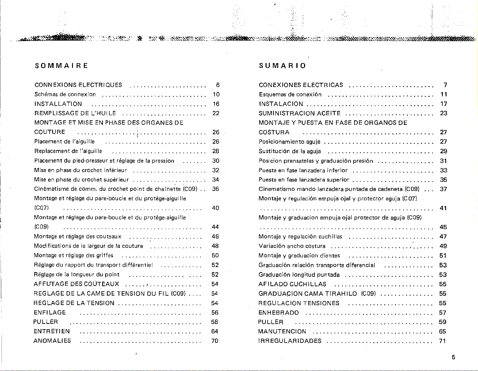
CONTENTS
INHALTSVERZEICHNIS
ELECTRICAL
CONNECTIONS
Connection diagrams
INSTALLATION
REFILLING
FITTING
MECHANISMS
Positioning
Replacing
Positioning
Timing
Timing
Chainstitch
Fitting
Fitting
Fitting
Variation
Fitting
Adjusting
Adjusting
SHARPENING
ADJUSTING
ADJUSTING
THREADING
PULLER
MAINTENANCE
FAULTS
WITH
AND
ADJUSTING
. . . . . . . . . . . . . . . . . . . . . . . . . . . . . • . . . . . .
the needle
the
needle 28
the
presser
the
bottom
the
top
looper
looper
and
adjusting
and adjusting
and
adjusting
of
and .adjusting
the
the
control
bight
width
differential
stitch
THE
THREAD
TENSION
....................................
. . . . . . . . . . . . . . . . . . . . . . . . . . . . . . . . . . . . . . 58
.......................................
OIL
looper . . . . . . . . . . . . . . . . . . . . . . . . . . .
length . . . . . . . . . . . . . . . . . . . . . . . . . . . 52
.....................
............................
THE
SEWING
foot
and
adjusting
. . . . . . . . . . . . . . . . . . . . . . . . . . . . .
mechanism.IC09) . . . . . . . . . . . . . . 36
front
and rear needle guards (C07)
front
and rear needle guards (C09)
cutters
the
CUTTERS
TAKE-UP
.•.......................
feed dogs . . . . . . . . . . . . . . . . . . . .
feed
ratio
...............
CAM
. . . . . . . . . . . . . . . . . . . . . . . . . . . .
its pressure . . . . . . .
. . . . . . . . . . . . . . . . . . . .
:........
(C09)
...........
:.
. . . . . . . . . . .
6
10
16
22
~6
26
30
32
34
40
44
46
48
50
52
54
54
54
56
64
68
ELEKTRISCHE
Anschluss-Skizzen
INSTALLATION
OELVERSORGUNG
MONTAGE
NAEHELEMENTE
Nadelstellung
Nadelaustausch . . . . . . . . . . . . . . . . . . . . . . . . . . . . . . . . . . . . 28
Positionieren des Driickerfusses und
Einstellen des
Phaseneinstellung
Antriebsgetriebe
Montage und Einstellung
sowie Nadelschutzes
Montage
und des Nadelschutzes
Montage
Aenderung
Montage
Regulierung des
Stichliingen-Regulierung
SCHLEIFEN
REGULIERUNG
SPANNUNGSEINSTELLUNG
EINFAEDELN
PlJ
WARTUNG
ABNORMITAETEN
und
und
und
LLER
ANSCH
UND
PHASENEINSTELLUNG
....................................
Untergreifers
Obergreifer
Kettenstichgreifer
Regulierung des vorderen Nadelschutzes
Einstellung
der
Ueberwendlichbreite
Regulierung
Differentialtransport
DER
DES
....................................
. . . . . . . . . . . . . . . . . . . . . . . . . . . . . . . . . . . . . . . 58
.......................................
LUESSE
...............................
DER
. . . . . . . . . . . . . . . . . . . . . . . . . . . . . . . . . 26
Driickregulierung
. . . . . . . . . . . . . . . . . . . . . . . . . . . 32
. . . . . . . . . . . . . . . . . . . . . . . . . 34
(C0,9)
der
vorderen Nadelschutzes
(C07) . . . . . . . . . . . . . . . . . . . . . . . . . . . . 40
(C09) . . . . . . . . . . . . . . . . . . . . . . . . . . 44
der
Messer . . . . . . . . . . . . . . . . . . . . 46
der
Transporteure . . . . . . . . . . . . . . 50
....
·I·
........................
MESSER
FADENSPANNUNGS-NOCKENS(C09)
................................
.........................
. . . . . . . . . . . . . . . . . . . . . . . . 54
. . . . . . . . . . . . . . . . 36
. . . . . . . . . . . . . . . . . . . . 48
Verhiiltnisses
. . . . . . 30
........
..
10
16
22
26
52
52
54
54
56
64
69
6
4
1:
'
..
:':':
,',
"•
Page 6
'
.,-.;,:ti¢}®;tri)fU.!tM-:~--;.:.··
·
::>~;__:.?1~~-;-
~~
.!-:~::~
·~-:
:
::f.z~:~:~
~;;£~:.
~:~:j;.-!.::.Jit'Hifbir•"'i:·::-:-:.x~&.!&'·::~-;::-:·:t~
·;.·
~
·:::;~~:-t~~Yo;~~~~-~~:*~:·2--:::~-.1:0:-~
SOMMAIRE
CONNEXIONS
Schemas de
INSTALLATION
REMPLISSAGE
MONTAGE
COUTURE
Placement de l'aiguille
Replacement
Placement du pied-presseur et reglage de
Mise en phase du
Mise en phase du
Cinematisme
Montage
(C07)
Montage
(C09)
Montage
Modifications
Montage
Reglage
Reglage de
AFFUTAGE
REGLAGE
REGLAGE
ENFILAGE
PULLER
ENTRETIEN
ANOMALIES
et
et
et
et
du
ELECTRIQUES
connexion
DE
ET
MISE
.................
de
l'aiguille
crochet
crochet
de
comm.
reglage
reglage du pare-boucle
reglage
de
Ia
reglage
rapport
Ia
longueur du
DES
DE
LA
DE
LA
. . . . . . . . . . . . . . . . . . . . . . . . . . . . . .
L'HUI
LE . . . . . . . . . . . . . . . . . . . . . . . . 22
EN PHASE DES
............................
. . . . . . . . . . . . . . . . . . . . . . . . . . .
inferieur
superieur
du crochet
du
pare-boucle
des
couteaux
largeur
des
du
COUTEAUX
CAME
TENSION
de
Ia
griffes
transport
point
DE
couture
TENSION
.......................
...........................
I
. . . . . . . . . . . . . . . . . . . . . 32
....................
point
et
du
et
du protege-aigu ille
differentiel
. . . . . . . . . . . . . . . . .
......
ORGANES
..................
Ia
pression
de
chainette
protege-aiguille
...........
,
..............
DU
Fl
L (C09)
DE
(C09)
'
......
...
..
SUMARIO
6
10
16
.
26
.
26
28
30
,
34
36
40
44
46
48
50
.
52
.
52
54
.
.
54
.
5~-
56
58
.
64
70
CONEXIONES
Esquemas de
INSTALACION
SUMINISTRACION
MONTAJE Y PUESTA
COSTURA
Posicioilam iento aguja
Sustituci6n
Posicion prensatelas y graduaci6n presi6n
Puesta
Puesta
Cinematismo
Montaje
Montaje
Montaje
Variaci6n ancho costura
Montaje
Graduaci6n
Graduaci6n
AFILADO
GRADUAciON
REGULACION
ENHEBRADO
PULLER
MANUTENCION
IRREGULARIDADES
en
en
y regulaci6n
y graduacion
y regulaci6n cuchillas
y graduacion
ELEGTRICAS
conexi6n
.....•.........................•....
....................••...............
de
Ia
aguja
fase lanzadera
fase
lanzadera superior
mando
relaci6n
longitud
CUCHILLAS
CAMA
TENSIONES
...................................
......................................
.............................
ACEITE
EN
FASE
..............................
..............................
inferior
lanzadera
empuja
empuja
dientes
transporte
pun
..................•...............
ojal y protector
ojal
.......................
tad a .........................
...........................
TIRAHILO
.............................
.....................•...
DE
ORGANOS
.......................
......................
puntada
protector
.......................
diferencial
(C09)
DE
................
de cadeneta (C09)
aguja (C07)
de aguja (C09)
·
.....
..............
7
.
11
17
23
27
27
.
.
29
.
31
.
33
.
35
37
41
45
47
.
.
49
51
53
.
53
55
.
.
55
55
.
57
.
59
65
.
71
5
Page 7
ELECTRICAL
Before
mains
connecting
supply
Check
terminal
suited
motors
highest
sketches).
If
the
check
amperage value
After
holder plugs so
electrical
If
the
check
motor
to
the
Table
To
calibrator
screw A so
corresponds
that
board
to
the
are
permitted
plant
that
checking
contact.
plant
that
power
amperage value
2.
vary
remove
CONNECTIONS
the
motor
proceed
they
it
the
to
as follows:
connection
inside
current
connected
has switch
indicated
that
has a
is
calibrated
and its effective
that
the
the
supply,
voltage (see
correspond
tighten
there
motor
motor
the
cover and
the
value required.
to
to
motor
since all
for
their
with
fuses,
to
in
Table
the
is
perfect
protector;
to
suit
current
indicated
protector
turn
mark
on
the
the
is
the
1.
fuse
the
in
it
ELEKTRJSCHE
Bevor
schlossen wird, muss man
der
Motor
Sich davon
luss
des
derjenige ist,
Spannung
wi
rd
da
fur
die
zugelassene
geliefert
Wenn die Anlage
mit
Sicherungen
man sich
selben,
des
fuhrspannung
auf
Nach
gerstiipsel bis
um
Kontakt
Wenn die Anlage
schurz
davon
desselben,
keit des
Spannung,
Ampere-Wert
ung des
muss
die
auf
derlichen
auf
Motors
Tab. 1
der
einen
versehen ist,
uberzeugen, dass
Motors
Motorschutzes
man
Schraube A derart
ihr
bestehende
ANSCHLUESSE
an
das
uberzeugen,
inneren
des
aile
hochste,
werden.
davon
Basis
angefuhrt
Kontrolle
zu sichern.
auf
dem
den
wert
Motor-Kiemmbrettes
der
Zufuhrnetzes
Motoren,
vom
Spannung
mit
versehen ist, muss
uberzeugen,
der
und
seiner
dem
zum
Boden
perfekten
mit
Basis
und
in Tab. 2
entspricht.
Deckel
Zeichen
entspricht.
Zufu
effektiv
Leistungsfahigkeit
Ampere-Wert,
ist.
die Sicherungstra-
muss
der
seiner
hrnetz
folgendes
dass
angesch lassen
Motor
(siehe Skizze)
einem
effektiven
entsprechen.
zuschrauben,
elektrischen
einem
die
Leistungsfahig
angefuhrten
Um die Eich-
zu veriindern,
abnehmen
drehen,
dem
ange-
der
Ansch-
von
gefordert
selbst
Schalter
dass die-
Motor-
man sich
Eichung
effektiven
dass das
erfor-
tun:
der
Zu-
der
und
CONNEXJONS
Avant
d'alimentation
de
brancher
Verifier
borne
effectivement
Ia
tension
moteurs
pour
par
le
Si
!'installation
d'un
fusibles
Ampere
selon
tension
Apres
bouchons
d'assurer
electrique.
Si
l'installation
d'un
tarage
valeur en
tableau
moteur
d'alimentation.
Pour
disjoncteur,
fa ire
le
signe
en
demandee.
que
interne
d'alimentation
sont
Ia
tension
moteur
coupe-circuit,
correspondent
indiquee
Ia
puissance
d'alimentation
le
controle
disjoncteur
de
Ampere
2,
et
modifier
tourner
qui
correspondance
ELECTRIQUES
le
moteur
il
faut:
Ia
connexion
du
moteur
celle necessaire
fournis
maximum
(voir
schemas).
electrique
controler
a la'valeur en
dans
du
rnoteur
serrer a fond
porte-fusibles
un
celui-ci
selon
enlever
se
parfait
electrique
controler
corresponde a Ia
indiquee
Ia
puissance du
Ia
tension
le
le
Ia
vis
de
fa9on
trouve
sur
de
au
reseau
de
pour
car
tousles
predisposes
permise
est
dotee
que
le
tableau
et
effective.
contact
est
dotee
que
dans
effective
tarage
couvercle
a ce que
celle-ci
Ia
valeur
Ia
soit
les
1,
sa
les
afin
le
le
du
et
so
it
6
Page 8
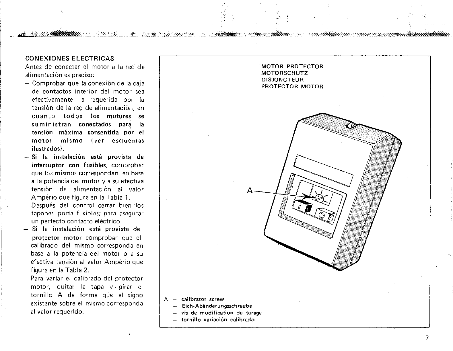
CONEXIONES ELECTRICAS
Antes
alimentacion
-
de
conectar
es
Comprobar
contactos
de
que
efectivarnente
tension
cuanto
de
todos
Ia
suministran
tension
motor
maxima
mismo
el
motor a Ia
preciso:
Ia
conexion
interior
Ia
requerida
red
de
los
conectados
consentida
(ver
del
alimentacion,
motores
ilustrados).
-
Si
Ia
instalacion esta
interruptor
que
los mismos
Ia
potencia
a
tension
Amperio
de
que
Despues del
tapones
un
Si
porta
perfecto
Ia
instalacion esta
protector
calibrado
base a
efectiva
figura
del
Ia
potencia
te(lsion
en
Ia
Para variar
motor,
tornillo
existente
al
valor
quitar
A de
sobre
requerido.
con
fusibles,
correspondan,
del
motor
alimentacion
figura en
control
fusibles; para asegurar
contacto
motor
comprobar
mismo
del
al
valor
Tabla
el
2.
calibrado
Ia
forma
el
mismo
provista
y a su efectiva
Ia
Tabla
cerrar
electrico.
provista
corresponda
motor
Amperio
del
tapa
y.
que
corresponda
red
de
de
Ia
caja
motor
sea
por
en
se
par<i
I
por
el
esquemas
de
comprobar
en base
al
valor
1.
bien
·los
de
que
el
en
o a su
que
protector
girar
el
el
signo
Ia
Ia
A
calibrator
Eich-
vis
de
tornillo variaci6n calibrado
screw
Ab3nderu
modification
ngssch
rau
be
du tarage
MOTOR
MOTORSCHUTZ
DISJONCTEUR
PROTECTOR
PROTECTOR
MOTOR
;~
'
.
'
7
Page 9
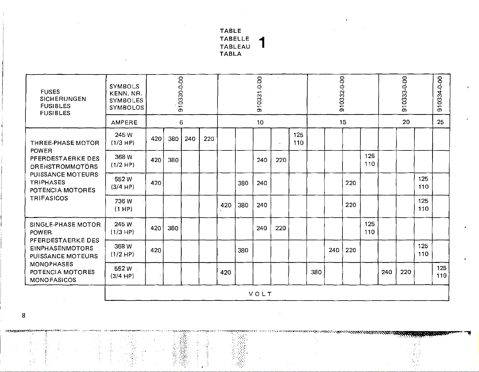
TABLE
TABELLE
TABLEAU
TABLA
1
FUSES
SIGH
ERUNGEN
FUSIBLES
FUSI BLES
THREE-PHASE
MOTOR
POWER
PFERDESTAERKE
DR
EHSTROMMOTbRS
PUISSANCE
MOTEURS
DES
TRIPHASES
POTENCIA
MOTOR
ES
TRIFASICOS
SINGLE-PHASE
MOTDR
POWERPFERDESTAERKE
DES
EINPHASENMOTORS
PUISSANCE
MOTEURS
MONO PHASES
POTENCIA
MOTORES
MONOFASICOS
SYMBOLS
KENN.
NR.
SYMBOLES
SYMBOLOS
AMPERE
245W
(1/3
HP)
368W
(1/2HP)
552W
(3/4 HP)
736W
(1
HP)
245W
(1/3
HP)
368W
(1/2HP)
552W
(3/4
HP)
420
420
420
420
420
380
380
380
D
D
6
6
M
M
D
~
Ol
6
240
220
420
420
380
380
380
D
q
q
~
M
M
D
~
Ol
10
240
240
240
240
220
220
125
110
380
D D D
D D
6 6
N
M M M
M
D 0 0
~
Ol
15
125
110
220
220
125
110
240
220
240
o1
M M
~
.Ol
20
220
125
110
125
110
125
110
9
q
...
~
Ol
25
125
110
8
.~zy~s-.r
....
.t:.rr,.,-,r.nz-
......
-.."0"\
.. --... ~ ..
,-
.·-r-,..~·
~-·
-,
-·-··
-~---.-.:~-
. c
...
;--~~
~~
...
-~.""<
....
..,..-~"!"',.·
•.. '
.•
-·~·-·'
'
VOLT
Page 10
.,
·:·-.•.
--~
•."'.·
--·.
·•··
._
"':
......
<",•,,•
·.-
•..
· •• •
.•
··.-~-.-:
..•
•,
,·.'-_-....,...
.. • ..
·".'.·+·
.. • ...
,;.
......
_,•.",,
.....
,~-;._.,.,~
......
~
••
--'-4
~···
o'
_:
•
---:t\~
TABLE
TABELLE
TABLEAU
TABLA
........,,
•..
'~~_,.._..,.,.,-
..
,.,
2
·.-"·>}~:._.~-~'~
~
,"'
...•.
.
·.•·
~
. •
....
,.:.,;,,.,·
·.-
...
.:-.-~.~
.....
_«~<f.Ji..
-
.-.......,
-.-.
........
-..~.·r:.r
.....
~--..-'"'.·..r."',".-,..·.-:·r.·.•tfr.·..:"r~
... . ....
~
....
.:L.·--, -..
...
:.-.:r
..
~~
~lL
'"'"
~~~~~j
···-.'~
......
..
...
~.
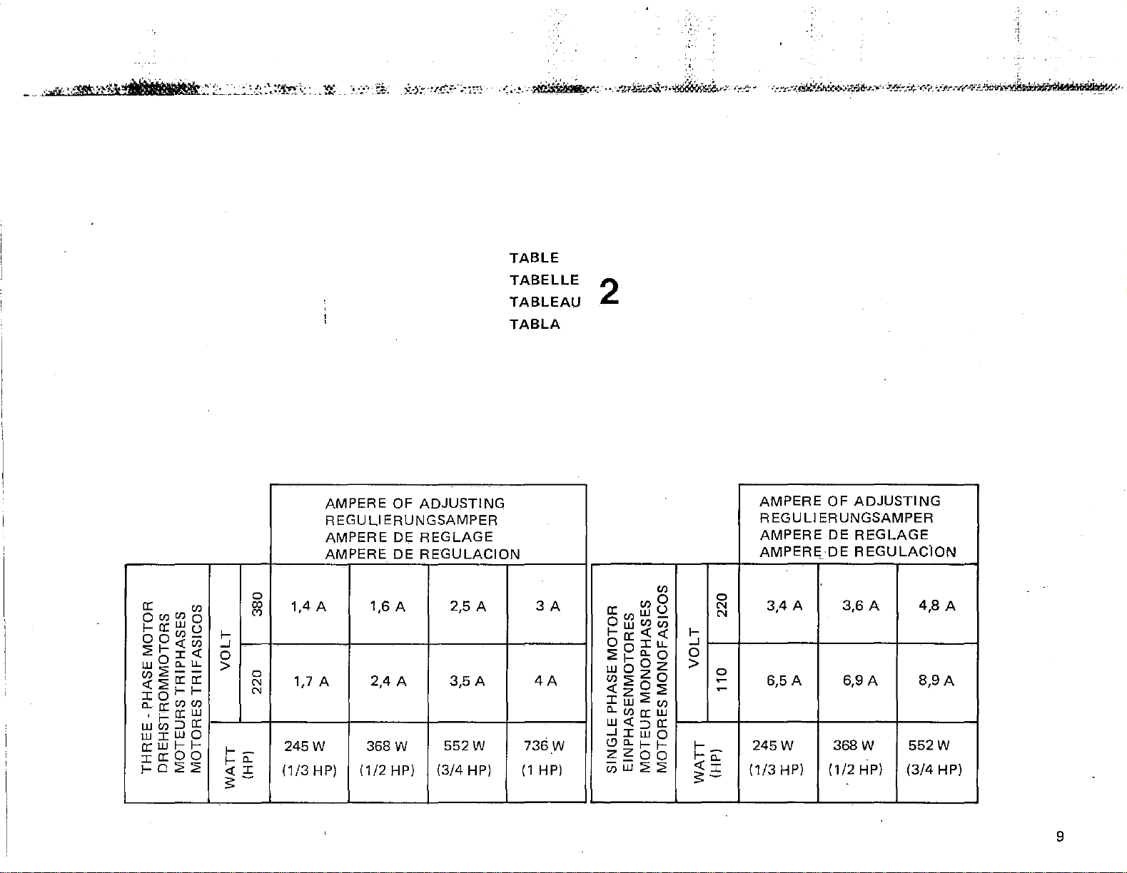
AMPERE
OF
ADJUSTING
REGULIERUNGSAMPER
a:
QCilCilQ
1-a:wu
oo"'-
::;;1-<(Cil
J:<C
wOa..u..
[/)::;;--
<(:;;a:a:
:col-I-
a..
a:
(f.)(/)
'1-a:::w
WC/l:JCI:
w:cwo
a:wl-1:ca:OO
!-0::;;2
C/l
1-
-'
0
>
1--
!-0.
<(I
:;::-
AMPERE
AMPERE
0
CXl
1,4 A 1,6 A 2,5 A
C')
0
N
N
1,7 A
245W
(1/3
HP)
DE
REGLAGE
DE
REGULACION
2,4 A 3,5 A
368 w
(1/2
HP)
552W
(3/4
HP)
3A
4A
736W
(1
HP)
C/l
"'o
a:C/lwU
Ow"'ti>
1-a:<C<C
OoiLL
::;;1-a.o
0
wo
"':;;zo
<CzO:;;
Iw:;;C/l
c...cna:w
W<C;:JCI:
-'Iwo
(!)a.
z
I-I-
zzoo
u;w:;;:;;
1-
-'
0
>
1=-
<(a.
:;::2:
AMPERE
REGULI
AMPERE
AMPERE_
0
N
N
0
~
~
3,4 A
6,5A 6,9A
245W
(1/3
HP) (1/2 HP)
OF
ADJUSTING
ERUNGSAMPER
DE
REGLAGE
DE
REGULAC"ION
3,6
A
4,8
8,9A
368W
552W
(3/4
A
HP)
9
Page 11
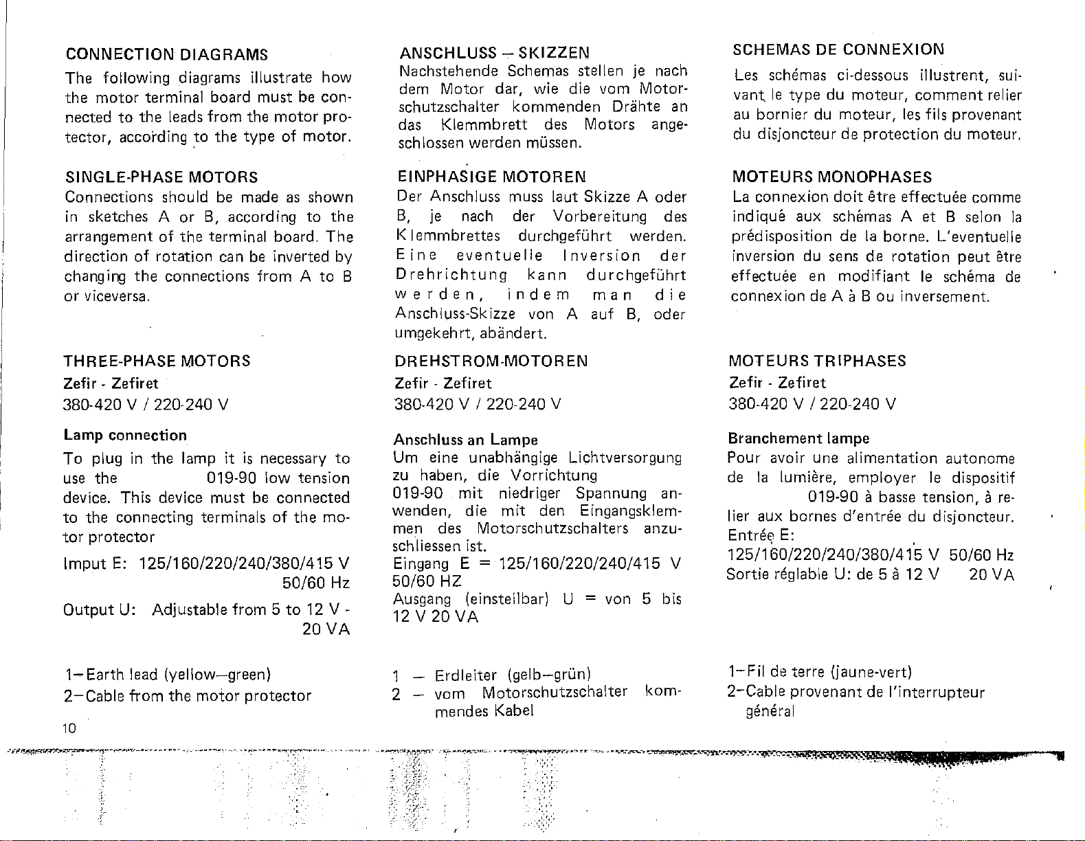
CONNECTION
The
following diagrams
the
motor
nected
tector,
terminal
to
the
according
DIAGRAMS
board
leads
from
to
the
illustrate
must
the
motor
type
of
how
be
con-
pro-
motor.
ANSCHLUSS-
Nachstehende
dem
schutzschalter
das
sch lossen
Motor
Klemmbrett
werden
SKIZZEN
Schemas
dar,
wie
kommenden
des
mi.issen.
stellen
die
vom
Motors
je nach
Motor-
Driihte an
ange-
SCHEMAS
Les
schemas
le
vant,
au
du d
type
bornier
isjoncteur
DE
CONNEXION
ci-dessous
du
moteur,
du
moteur,
de
protection
illustrent,
comment
les fils
du
sui-
relier
provenant
moteur.
SINGLE-PHASE
Connections
in
sketches
arrangement
direction
changing
or
viceversa.
THREE-PHASE
Zefi r 380-420 v /220-240
Lamp
To
plug
use
device.
to
the
tor
protector
lmput
Output
of
the
Zefiret
connection
in
the
This
connecting
E:
125/160/220/240/380/415
U:
MOTORS
should
A
or
of
the
rotation
connections
MOTORS
the
lamp
device
Adjustable
be
made
B,
according
terminal
can
be inverted by
from A to
v
it
is
019-90
must
terminals
be
from 5 to
as
shown
to
board.
necessary
low
tension
connected
of
the
50/60Hz
12
20
the
The
to
mo-
V
V-
VA
B
EINPHASIGE
Der
Anschluss
B,
je nach
K I
emmbrettes
E
ine
Drehrichtung
werden,
Anschluss-Skizze von A
umgekeh
DREHSTROM-MOTOR
Zefir 380-420
Anschluss
Um
zu
019-90
wenden,
men
schliessen ist.
Eingang E
50/60HZ
Ausgang (einstellbar) U = von 5 bis
12
Zefiret
eine
haben,
des
V
20
eventuelle
rt,
V I
mit
VA
MOTOREN
muss laut
der
durchgefi.ihrt
kann
indem
abandert.
220-240
an
Lampe
unabhiingige
die
Vorrichtung
niedriger
die
mit
den
Motorschutzschalters
=
125/160/220/240/415
Skizze A oder
Vorbereitung
Inversion
durchgefuhrt
auf
EN
v
Lichtversorgung
Spannung
Eingangsklem-
man
des
werden.
der
die
B,
oder
an-
anzu-
V
MOTEURS
La
connexion
indique
predisposition
inversion
effectuee
connexion
MOTEURS
Zefir -
380-420 v /220-240
Branchement
Pour
de
lier
125/160/220/240/380/415
Sortie
avoir
Ia
aux
Entre~
reglable U:
MONOPHASES
doit
aux
schemas
de
du
sens
en
modifiant
de A a B
TRIPHASES
Zefiret
lampe
une
lumiere,
019-90
bornes
E:
etre
Ia
borne.
de
rotation
ou
v
alimentation
employer
a basse
d'entree
de
5 a
effectuee
A
et
le
inversement.
le dispositif
tension, a re-
du
.
V
12
V
comme
B selon
L'eventuelle
peut
schema
autonome
disjoncteur.
50/60
20
Ia
etre
de
Hz
VA
1~
Earth
2~Cable
10
lead
(yellow-green)
from
the
motor
protector
.,·.
2
1
Erdleiter
vom
mendes
Motorschutzschalter
Kabel
(gelb-gri.in)
kom-
1~Fil
2-Cable
de
general
terre
(jaune-vert)
proven
ant
de
l'interrupteur
Page 12
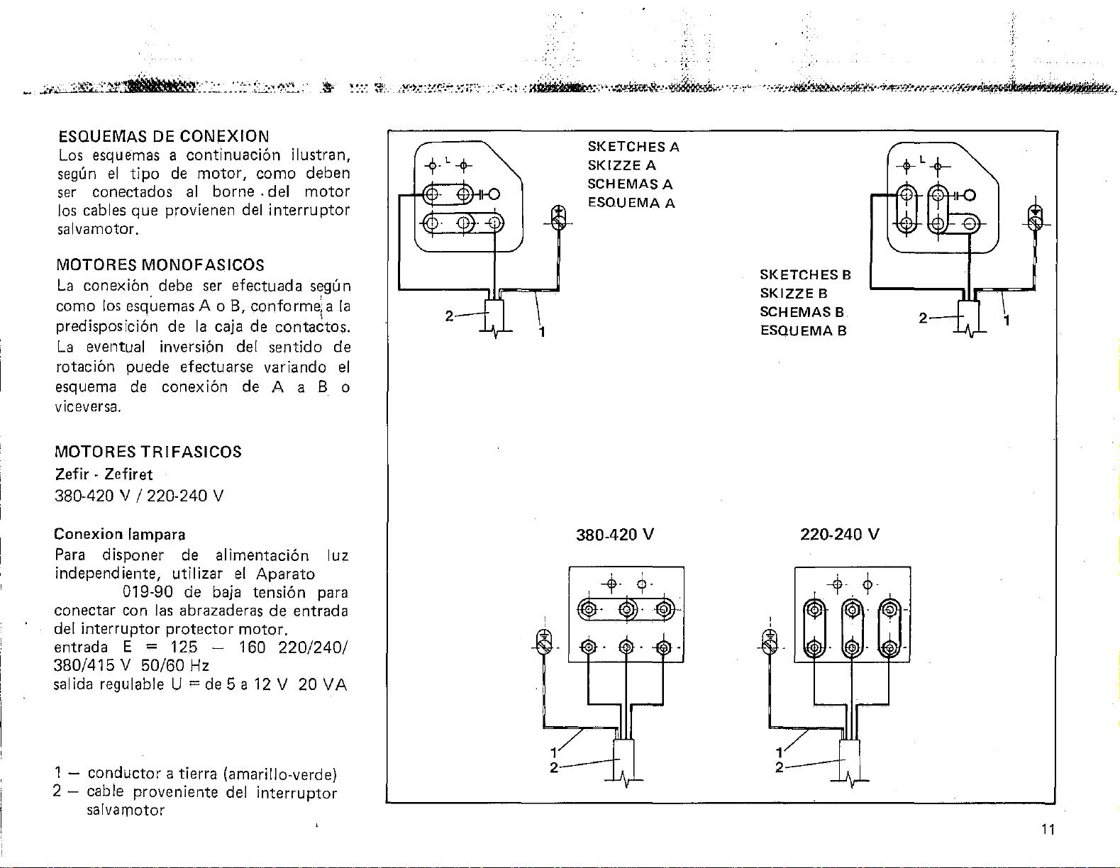
ESQUEMAS DE
Los
esquemas a continuaci6n ilustran,
el
segun
tipo
ser conectados
los
cables que provienen
CONEXION
de
motor, como deben
al
borne . del motor
del
interrupter
salvamotor.
+L+
SKETCHES
SKIZZE
SCHEMAS A
ESQUEMA
A
A
A
MOTORES MONOFASICOS
La
con
ex
ibn
debe ser efectuada
como
predisposici6n de
La
los
esquemas A o
B,
conforme:a
Ia
caja de contactos.
eventual inversion del sentido de
segu
I
rotacibn puede efectuarse variando
esquema
de
conexi6n de A a B o
viceversa.
MOTORES
Zefir
· Zefiret
TRIFASICOS
380-420 v I 220-240 v
Conexion
lampara
Para disponer de alimentaci6n luz
independ iente, utilizar
el
Aparato
019-90 de baja tension para
conectar con
del
interrupter protector motor.
entrada
380/415 V 50/60
salida regulable U
las
abrazaderas de entrada
E = 125 - 160
Hz
=de
5 a
12
220/240/
V 20
VA
Ia
el
n
2
1
380-420
v
SKETCHES
SKIZZE
SCHEMAS B
ESQUEMA
8
220-240
B
B
v
2
1
1 - conductor a tierra (amarillo-verde)
2 - cable proveniente
del
interrupter
salvamotor
11
Page 13

THRE&PHASEMOTORS
QUICK
(up
QUICK STOP
(up
NDK
600 V
to
serial
no.
1,610, 199)
NDK
to
serial no. 580, 199)
700
DR EHSTROM-MOTOR
QUICK
(bis
QUICK STOP
(bis
NDK
600 V
zu
Matrikei-Nr. 1.610.199)
NDK
zu
Matrikei-Nr. 580.199
700
EN
MOTEURS
QUICK
TRIPHASES
NDK
600 V
(jusqu'au numero
QUICK
(jusqu'
STOP
au
numero
NDK
de
matricule 1.610.199)
700
de
matricu
le
580.199)
THREE-PHASE MOTORS
QUICK
(from
QUICK
NDK
seria.l
STOP
600 V
no. 1,61 0,200)
NDK
700 and
(from serial no. 580,200)
QUICK
ELECTRONIC
880, 880T, 880BG, 880M
1
-earth
2 - cable
3 4-
5
-transformer
6 - panel
12
lead (yellow/green)
from
main
motor
feed
term
ina I
cable Z
terminals
switch
board
of
transformer
for
controls
NDK
NDK
707
800,801,
DREHSTROM-MOTOREN
QUICK
(ab
QUICK
(ab
QUICK
NDK
600 V
Matrikei-Nr. 1.610.200)
STOP
NDK
und
NDK
Matrikei-Nr. 580.200)
ELEKTRONIK
NDK
880;880T;880BG;880M
1 -
Erdleiter
2
-
vom
3-
Motor-Kiemmbrett
4 -
Zufuhrkabel Z des
5-
Transformator
6-
Endteile
(gelb-grun)
Generalschalter
fUr Steuerungen
der
Steuerplatte
kommendes
Transformators
707
800;
Kabel
801;
MOTEURS TRIPHASES
QUICK
(a
partir
NDK
600 V
de
numero de matricu
1.61 0.200)
QUICK
(a partir
STOP
du
numero
NDK
700 et
de
matricule
580.200)
QUICK
880,880T,
1 - fil
2-
3 - borne du
4-
5 - transformateur
6
-term
ELECTRONIC
880BG,880M
'
de
terre
(jau ne-vert)
cable provenant
moteur
cable d'alimentation Z
inaux du panneau
de
l'interrupteur
command~
du
le
NDK
NDK
transformateur
707
800,801,
general
.
~-"'711~-"--'...-!\-,,.,,....,
·:::.:
··;;:
i·,·-.
·:
..
-:.-:
.·
,,
........
~-""-~~·~---'
-"
-~
,-
......
_.-_-
__
._
..... ~ •
.,_-~
...
..,~.:-.-.---~~
.......
,.-
........
----~-~----.;.'Jt"--l'd~'liS,it'"~~~¥111!111-A$.2.}f.i#i
..
I "
i*
·'
AW'""'V
Page 14
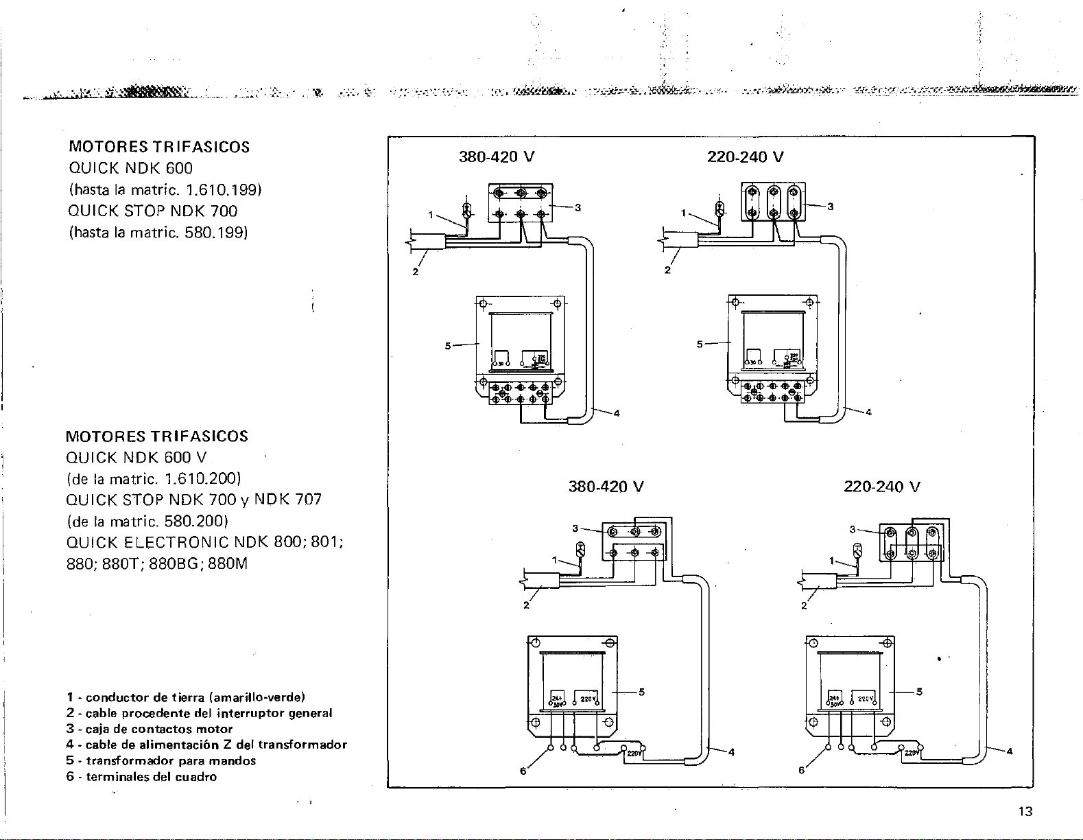
MOTORES TRIFASICOS
QUICK
(hasta
QUICK STOP
(hasta
NDK
600
Ia
matric. 1.610.199)
NDK
700
Ia
matric. 580.1 99)
380-420 v 220-240 v
3
3
MOTORES TRIFASICOS
QUICK
(de
NDK
Ia
matric. 1.61 0.200)
QUICK STOP
(de
Ia
matric. 580.200)
QUICK ELECTRONIC
600 V
NDK
700 y
NDK 800; 801;
880;880T;880BG;880M
NDK
707
2
5
4
380-420 v
2
5
4
220-240 v
3
1~
'l
n
I
~
~($'
f
~
!)
~
~
2
"'
7
0
~
..
1
·conductor
2-
cable procedente del
3 - caja
4-
cable
5 - transformador
6 - terminales del cuadro
de
de
contactos
de
alimentacion
tierra
(amarillo-verde)
interrupter
motor
para
mandos
Z del
transformador
general
. '
5
SM
l--5
¢ -0
1
4
6
6
,.t
I--
4
13
Page 15
THREE-PHASE MOTORS
EFKA
VARIOSTOP
220
V
DREHSTROM-MOTOREN
EFKA
VARIOSTOP
220
V
MOTEURS TRIPHASES'.
EFKA VARIOSTOP
220
V
THREE-PHASE MOTORS.
EFKA
1 -
245-
67-
91011
13-
1415-
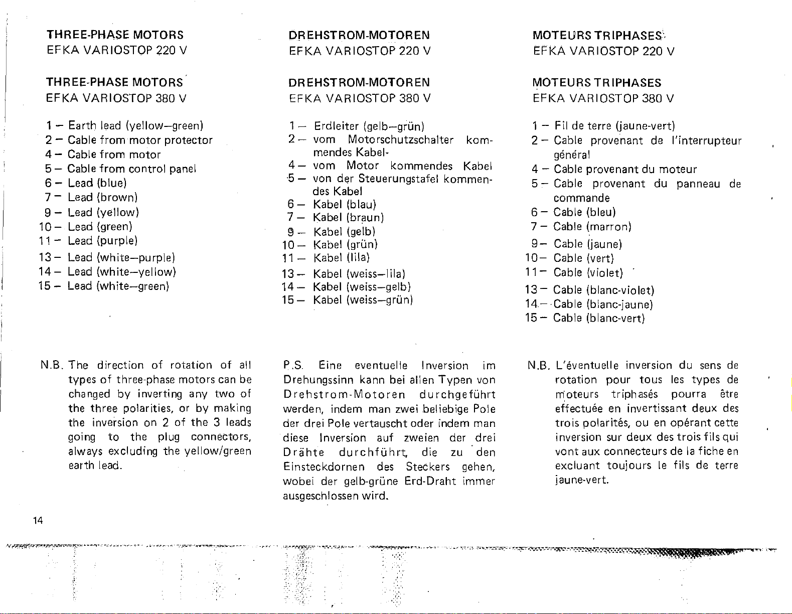
N.B.
VARIOSTOP
Earth
Cable
Cable
Cable
Lead (blue)
Lead (brown)
Lead (yellow)
Lead (green)
- Lead (purple)
Lead
Lead
Lead
The
types
changed
the
the
going
always excluding
earth lead.
lead
(yellow-green)
from
motor
from
from
(white-purple)
(white-yellow)
(white-green)
direction
three
inversion
motor
control
of
three-phase
by
polarities, or
to
the
380
protector
of
inverting
on 2 of
plug
the
V
panel
rotation
motors
any
two
by
making
the
3 leads
connectors,
yellow/green
of
all
can be
of
DREHSTROM-MOTOREN
EFKA
1 - Erdleiter
2-
4-
·5-
6-
7-
91011
131415-
P.S. Eine eventuelle Inversion im
Drehungssinn kann bei
rehstro
D
werden,
der drei Pole
diese Inversion
Drahte
Einsteckdornen
wobei
ausgeschlossen
VARIOSTOP
(gelb-grun)
vom
mendes Kabelvom
von
des Kabel
Kabel (blau)
Kabel (braun)
Kabel (gelb)
Kabel (grun)
- Kabel (lila)
Kabel
Kabel
Kabel
Motorschutzschalter
Motor
der
Steuerungstafel
(weiss(weiss-gelb)
(weiss-grun)
m-
Mota
indem
vertauscht
durchfuhrt,
der
gelb-grune Erd-Draht immer
wird.
380
V
kommendes
I ila)
allen
re n d u
man
zwei beliebige Pole
auf
zweien der
des
Steckers
rchgefuhrt
oder
die zu ··den
kom-
Kabel
kommen-
Typen
indem
gehen,
von
man
drei
MOTEURS TRIPHASES
EFKA VARIOSTOP
1 - Fil de terre (jaune-vert)
2-
Cable
general
4 - Cable
5-
Cable
commande
6-
Cable (bleu)
7-
Cable
9-
Cable (jaune)
10-
Cable (vert)
11-
Cable (violet)
13-
Cable (blanc-violet)
14-
Cable (blanc-jaune)
15-
Cable (blanc-vert)
N.B. L'eventuelle inversion
rotation
m:
effectuee
trois
inversion sur
vont
excluant
jaune·vert.
provenant
provenant
provenant
(marron)
oteu
rs
polarites,
aux
pour
tr
en
connecteurs
toujours
380
de
du
moteur
du
taus
iph ases
invertissant
ou
en
deux
des
le
V
l'interrupteur
panneau
du
sens de
les
types
pourra
operant
trois
de
Ia
fils de terre
deux
cette
fils qui
fiche en
etre
des
de
de
14
Page 16
t._..
»"-.~";·:rtri.'rltPBtKt;;··~.._;:~~~.a,~_}
....
t;:·;-:
".
··it
-:~
...
:-··
7t · :..;.
.:.:~,·:-~
..
--:Lo:;.
::·
·-·'-
-..
·
,.-,~-:
::•
-;-~~~~~
.....
-.~
·
(~.~.:;::.
...
,~~:.".
·~~.;:~"
·
:-~·~.-:~.--
.
·-~-·w•~·~.!.i:Y.!<<o;;·,~.w
..
;o;-::•.7.t'tl"!::<-::~~o;·/
·.-:-'c:":~::·7!:..'-W~~~~#..nt.~::
' ,
MOTORES
EFKA
MOTORES
EFKA
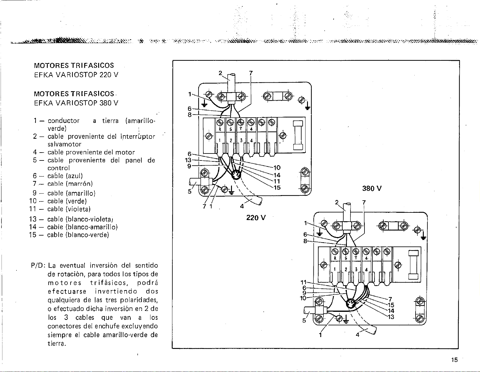
1 -
conductor
TRIFASICOS
VARIOSTOP
TRIFASICOS
VARIOSTOP
a tierra (amarillo-
220
380
V
V
verde) ,
2 - cable proveniente del
interruptor
salvamotor
4-
cable proveniente del
motor
5 - cable proveniente del panel
control
6-
caole (azul)
7 - cable (marr6n)
9 - cable (amarillo)
10-
cable (verde)
11
- cable (violeta)
13 - cable (blanco-violeta1
14-
15-
cable (blanco-amarillo)
cable (blanco-verde)
de
220V
380
v
P/0:
La
eventual inversion del senti
de rotacion, para todos I
motores
efectuarse
qualquiera
trifasicos,
invertiendo
de
las
tres polaridades,
os
o efectuado dicha inversion
los
3 cables que
van
tipos
podra
en
2 de
a
do
de
dos
los
conectores del enchufe excluyendo
siempre
cable amarillo-verde
de
el
tierra.
15
Page 17
1------------------
INSTALLATION
Machine
The
and its
is
already in
by means
done
1. Force
the
2. Set
the
sh_ock
head
installation
connection
position
of
the
as follows:
the
four
pins
attached
the
machine
holes
underneath
absorbers.
of
the
machine
to
the
motor
on
its
transmission
shock
on
to
the
absorbers
the
the
head
(which
mountings)
belt
is
on
to
base-plate.
base, placing
head
on
the
INSTALLATION
Oberteil
Bezi.iglich
Installation
Anschluss an
dem
Gestell
Antriebsriemen,
vorgegangen
1.
die vier
Kraft
Stifte
2.
Die
placieren
des
werden:
stossdaempfenden
auf
die eigens vorgesehenen
der
Sti.itzplatte aufdri.icken:
Maschine
und
Oberteiles
Stossdaempfenden
zentrieren.
des
Oberteiles und
den
Motor
montiert)
(bereits
mittels
muss folgendermassen
Puffer
auf
die
dem
unteren
auf
Gestell
Bohrungen
den
Puffern
auf
mit
v1er
INSTALLATION
Tete
Pour
!'installation
raccordement
monte
de
1.
2. Placer
sur
le
bati a
transmission),
Enfoncer
tampons
de
Ia
plaque
centrant
Ia
tete
avec
amortisseurs
Ia
machine
les
sur
se
trous
amortisseurs.
de
avec
I'
proceder
force
soutien
qui
les
Ia
tete
le
moteur
aide
d'une
comme
les
sur les goupilles
sur
le
se
trouvent
quatres
tampons
et
son
(deja
courroie
suit:
quatres
bati en
sous
A-
head
support
16
pin
A -
Oberteii-Haltestift
A ·
goupille
de
soutien
de
Ia
tete
!A'
...
ll
Page 18
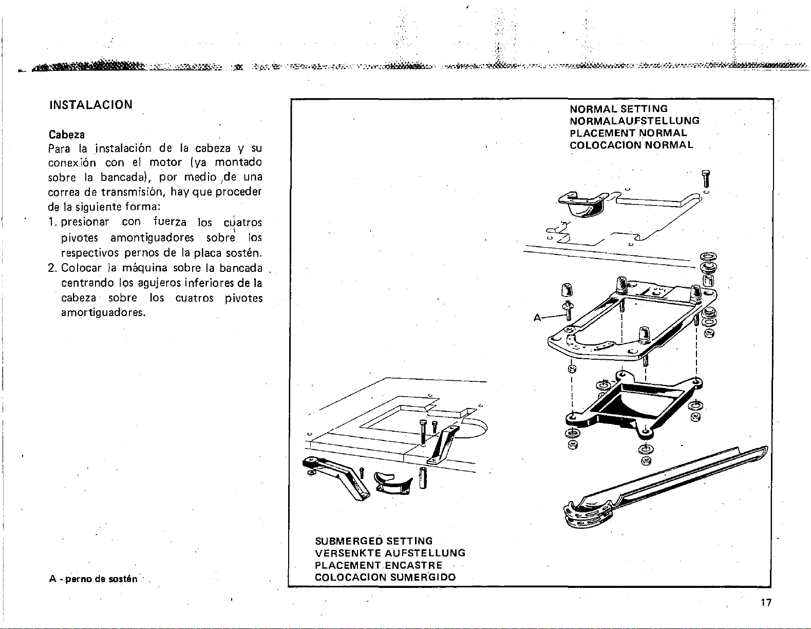
INSTALACION
Cabeza
Para
Ia
instalaci6n
conexi6n
sabre
correa
de
Ia
1.
presionar
pivotes
respectivos pernos
2.
Colocar
centrando
· cabeza ·
amortiguadores.
con
Ia
bancada),
de
transmisi6n,
siguiente
amontiguadores
Ia
sabre
forma:
con
maquina
los agujeros inferiores
el
de
motor
por
hay
fuerza
de
sabre
los
cuatros
Ia
cabeza
(ya
montado
med
io
,de
que
proceder
los
cuatros
sabre
Ia
placa sosten.
Ia
bancada
pivotes
y su
L!na
I .
los
de
Ia
NORMAL
NORMALAUFSTELLUNG
PLACEMENT
COLOCACION
SETTING
NORMAL
NORMAL
SUBMERGED SETTING
VERSENKTE
PLACEMENT ENCASTRE
A - parno de sostoln · ·
COLOCACION SUMER.GIDO
AUFSTELLUNG
17
Page 19
Belt
(figs.
To
connect
head a
indicated
1.
Fit
the
2.
Adjust
the
cannot
not
pulley-shafts
the
life
The
if
pressed
indicated
about
3. Level
belt
axes
This
support
relative
1-2)
the
motor
"V"
motor-fixing
belt
is
and
is
belt
in Fig. 1
belt
the
slip
too
of
10 · 15
the
perpendicular
thus
done
pins,
nuts
must
as
shown
belt
but
taut,
will be
the
is
correctly
by
in fig.
mm.
machine
centered
by
making
afterwards.
to
the
with
make
belt
dimensions
be
used.
in fig. 2
tension
screws so
sure
otherwise
overloaded
will
adjusted
hand
2,
at
the
by
be
belt
(3/8" · 9/16").
head so
to
the
in
their
adjusting
sure
to
machine
turning
that
that
it is
the
and
reduced.
when,
the
part
yields
that
the
pulley
races.
the
head
lock
the
as
it
R
iemen
Fur
unerlasslich
lt.
1.
2.
damit
der
Spannung
durch
des
ein
mm.
3. Das
bis sich
zu
befindet,
Hohlkehlen
muss
wirkt
dass
liessend
(Abb.
den
Abb.
Den
Antriebsriemen
Die
Riemenspannung
auf
das
stellen,
wird;
diesen
Riemenscheiben
und
die
nicht
langsten,
Durchbiegung
Nachgeben
Maschinenoberteil
den
auf
die
1-2)
Anschluss
einen
1 zu
verwenden.
Motor-Anschlussgelenk
dass
jedoch
nicht
Ueberlastungen
Lebensdauer
beeintriichtigt
ist
manuelles
der
Achsen
bzw.
arbeitet.
die
werden,
dazugehiirigen
blockiert
Motor-Obertei I ist
Keilriemen
lt.
Abb.
unter
ein
Schlittern
unter
ubermiissung
dann
freien
verwirklicht,
des
Riemen
in
Oberteii-Stutzbugel
wobei
Berucksichtigung
auf
vermieden
des R iemen
wird.
erreicht,
Drucken
Abschnittes,
Riemens
so
auf
der
Riemenscheiben
den
Zentren
Zu
zu
Muttern
werden
mit
Massen
2 n:10ntieren
Einwirken
so
verhindert
zu
spannen,
den
Wellen
werden
selbst
Die
richtige
wenn
im
das
von
livellieren,
Normalebene
diesem
beachten
mussen.
sich,
Zentrum
eine
heisst
10-15
derer
Zweck
einge-
ansch-
es
ein-
ist,
Courroie
Pour
faut
ayant
'
(figs. 1-2)
le
raccordement
employer
les
dimensions
1 .
Monter
1.
comme
2.
Regier
agissant
moteur
glissement,
pas
afin
arbres
compromettre
On a obtenu
en
Ia
courroie
3.
Centrer
a
perpendiculaire
c'est·a-dire
de
Pou,r cela agir
soui:ien
bloquer
le
Ia
Ia
tendre
d'eviter
de
appuyant
partie
flt§chit
Ia
ce
leur gorge.
de
successivement
moteur-tete,
une
courroie
indiquees a Ia
Ia
courroie
montre
tension
sur
l'axe
de
fa90n a empecher
mais
de
des
poulies
Ia
Ia
avec
libre
de
tete
de
que
qu'elle
Ia
tete,
de
Ia
fig. 2.
de
de
en
ayant
maniere
surcharges
et
duree
juste
tension
Ia
main
Ia
plus longue,
10-15
Ia
machine
Ia
courroie
aux
axes
travaille
sur
les goupilles de
en
trapezoi'dale
transmission
Ia
courroie
fixation du
soin de
excessive
sur
pour
de
ayant
les ecrous.
ne
Ia
courroie.
lorsque
au centre de
mm.
de
des poulies,
au centre
soin
II
fig.
en
tout
ne
les
pas
Ia
favon
soit
de
18
_.-
;
Page 20
:;
·~·~..,
·"~.trllt~~~.-.;:,_~,::;:;_{":{:;:::,:~~;:;x
.. -_,.
::·:~·
~
.-.
~t.-:~i-!-1i"f:.'t.-;:.:-
--:•
•:·,
.,_~
.....
,..
..
c •
.:.:~'"-W:'~-~~'i-"~~
..
~--~·.o:."
..
'; . ,
..
~_;-
....
~-:.~~
..
.t~·
..
~:'"!,'i.."'#r~·;•.;"'~·-'_-:-t(~.t"Z-;rJiNU"~~·
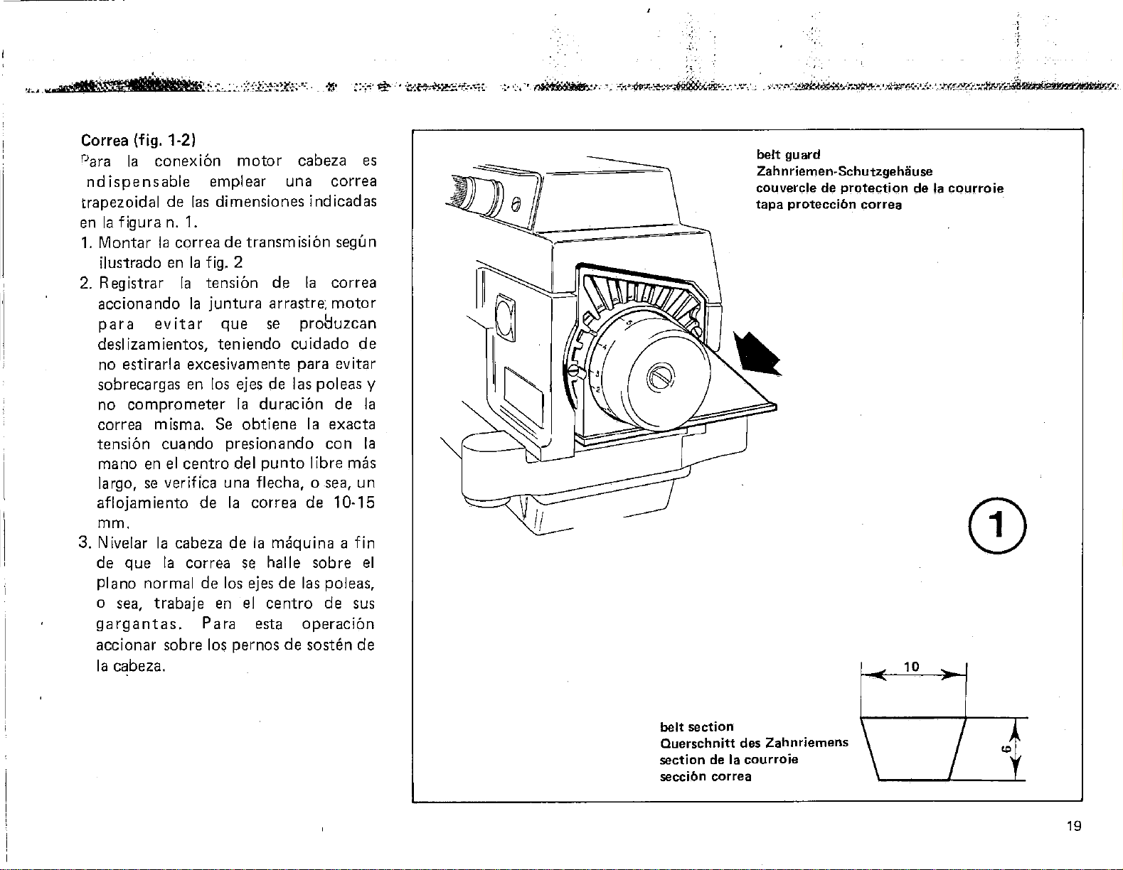
Correa (fig. 1-2)
Para
Ia
conexion
ndispensable
trapezoidal
en
Ia
figura n. 1.
1.
Montar
de
Ia
correa
ilustrado en
2.
Registrar
Ia
accionando
para
evitar
deslizamientos,
no
estirarla
sobrecargas
no
comprometer
correa
tension
mano
largo,
aflojam
misma. Se
cuando
en
el
se verifica una flecha, o sea,
iento
mm.
3. N ivelar
de
plano
o sea,
que
normal
Ia
cabeza
Ia
trabaje
gargantas.
accionar
Ia
cabeza.
sobre
motor
emplear
las
dimensiones
de
Ia
fig. 2
tension
Ia
juntura
que
teniendo
una
transmision
de
arrastre;
se
cuidado
excesivamente
en los ejes de las
Ia
duracion
obtiene
presionando
centro
correa
de
de
en
Para
los
del
punto
Ia
correa
de
Ia
se halle
los ejes
el
esta
pernos
maquina a fin
de
centro
de
cabeza
correa
indicadas
segun
Ia
correa
motor
pro8uzcan
de
para
evitar
poleas
de
Ia
exacta
con
libre mas
un
de
10-15
sobre
las poleas,
de
sus
operaci6n
sosten
de
es
y
Ia
Ia
el
belt
guard
Zah n riemen-
couvercle de protec::tion de Ia cql.)rroie
tapa proteccibn correa
Schutzgehiiuse
CD
10
belt
section
Querschnitt
section
seccibn correa
des
de
Ia courroie
Zahnriemens
"'
19
Page 21
4. Fix
the
on
machine.
N.B. Run
for
belt
pulley,
and
for
the·
then
speed.
the
belt
cover
the
the
in
machine
first
the
small race
to
ensure
at
twenty
perfect
therefore a much
the
machine.
belt
bring
into
Afterwards
the
the
machine
supplied
reduced
days,
with
of
the
motor
running· in
longer life
large race
to
with
speed
the
move
and
full
4.
Den
im
Maschinenzubehoer
mitgel ieferten R iemen-Schutzdeckel
montieren.
P.S. In
sich
Geschwindigkeit
der
Motor·
Die.s,
e ine liingere
selbst
Anschliessend
Kerbe
verlangern
z u
den
die
Riemen
R iemenscheibe
um
ein
gewaehrleistet
der
und
ge
I a
sse
n e
ersten
Maschine
20
Tagen
mit
empfiehlt
zu verwenden, indem
in
der
kleinen
montiert
perfektes
Lebensdauer
Einlaufen,
der
zu
den
Riemen in die grosse
Motor·Riemenscheibe
die Maschine
Hoc
hstg
eschwindigkeit
reduzierter
Rinne
Masch ine
erhalten.
bring en.
auf
es
der
wird.
das
die
Monter
4.
Ia
courroie,
N.B.
tourner
monter
de
Pendant
Ia
Ia
Ia
poulie
d'obtenir
une
plus longue
Ia
suite,
grande
faire
gorge
fonctionner
maximum.
le
couvercle
fourni
les
machine
courroie
du
un
rodage
duree
deplacer
de
de
avec
premiers
a vitesse
dans
Ia
moteur
parfait
de
Ia
Ia
courroie
Ia
poulie
Ia
machine a sa
protection
Ia
tete.
jours,
reduite
petite
dans
qui
le
assurera
machine.
dans
du
moteur
vitesse
de
faire
et
gorge
bui:
Par
Ia
et
20
,
·-:r.::"~'!f.r~''·
"".r-.·~,.
.
,-,
..
.,
....... _-.-
••
--~'Y·~ . ..,.~;,
.
-.-
.... , ··.-
...
-_-.-.-.·-·:-
.... _ ..
..;-.,
-.:----=.---~~-----:-·:-
-.·:-~·:-•.--":t:
....
a:.t~>:'l:"·:;.\l'?""'4'111.1\il:M~.I!'.
.•
i!!(QIIIJ.IJiliS!il'll.ZIII.
Ill,
'111#¥'/F''
"""
..
~--...-
Page 22
4.
Colocar
de
Ia
cabeza.
Ia
correa
en
P.S. Para los
emplearse
reducida
garganta
con
rod
aj e
duraci6n
desplazar
de
Ia
Ia
maquina
Ia
montando
pequefia
objeto
que
de
Ia
polea
consentida.
fin
Ia
tapa
de
protecci6n
con
Ia
que
esta
primeros
maquina a una
de
obtener
asegurara
Ia
maquina. A continLaci6n
correa
del
motor
a
Ia
Ia
de
Ia
en
Ia
y llevar
velocidad
viente
dfas
velocidad
correa
polea
del
un
una
garganta,grande
par
equipada
debe
en
Ia
motor,
perfecto
mayor
tanto
maxima
.,
~~·.,._,.,;_,~~~-·-·.··.·."·'··'-_,
.,.~.-·-.
··.·,·.c~~~~.·,-
,
.:x.
·.
· ·
:':~•
~
·
..
·.·.·,
•,'"···
.
-
-!,_~
___
_,_.,.
'{)'~~
_..,,.-.~.,~·,•.._,..,
-
.......
.-.:!."'-'".111lt..J<.~.-.!..:-~~-,
..
.,.
,·
'"''-''-'~
..._. ; ..
,.,
.....
~
·n·~
~M·,.
..
!<
••• -......
_._,,.:c--·~-
""•"'~-~
·--...:..:L"<..A_
..
..-
.-\.,:..:.
.•
·.:
•
..-L.:.
..
..
_"¢.-~i!Xi'JJ'T~~
;.;:.;"_..-.,-4..--t!I"J~--
........ .
®
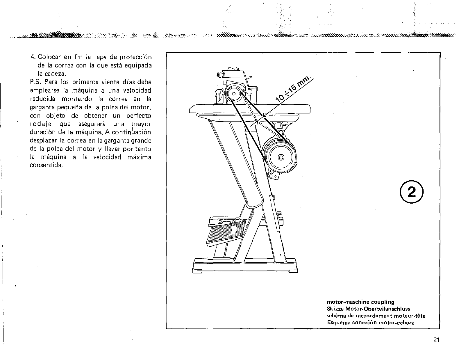
motor-maschine coupling
Skizze Motor-Oberteilanschluss
schema
Esquema conexibn motor-cabeza
de
raccordement moteur-tAte
21
Page 23

REFILLING
W!TH 0!!.. (figs.
3-4)
OELVERSORGUNG
(Abb.
3-4)
REMPLISSAGE
DE
L'HUILE
(figs
3-4)
The
lubricant
run
Standard
follows:
1.
2.
3.
4.
5.
6.
machine
it, oil
Unscrew
To
grams
Check
tbe
that
registering
Screw
Before
advisable
the
looper
Run
minutes,
from
is
despatched
therefore, . before
must
Teressa
transparent
fill
completely
of
oil
that
'max'
there
cap A on
starting
needle
articulated
the
machine
1500
be
32
into
the
oil
indicator B reaches
position,
is a certain
the
rise in oil level.
again.
to
put a few
clamp
gradually
r.p.m.
added,
and
cap
pour
sump.
bearing in
the
machine
drops
bar
joints.
empty
increasing
to
operating
without
starting
using Esso
proceeding
A
about
mind
delay
and
for
of
oil
the
about
speed
speed
in it
it
to
as
600
is
on
top
5
Die
Maschine
Schmiermittel
in
Gang
werden,
Schmiermittels
32
bedient
1.
Den
abschrauben
2.
Fur
man
schlitten.
3.
K o n t r o I I i e r e n , d a s s d e r
Oelstandsanzeiger
Position
bedenken
mit
Vergleich
Oelstandes
4.
Den
5.
Bevor
}
setzt,
Nadelhalterklemme
Gelenke
Tropfen
6. Die
leerlaufen
weise
man
Minute
gebracht
verlasst
und
muss
gesetzt
und
durchsichtigen
eine
in das
einer
Stopsel A wieder
man
ist
der
Oel
Maschine
die
sie
von
auf
hat.
wird,
indem
wie
komplette
erreicht.
muss,
gewissen
bewegt.
die
es
Obergreifers
zu
lassen,
Geschwindigkeit
1500
die
man
Esso
Standard
folgt
Loch
B
dass
zur
Maschine
ratsam
schm
zirka
indem
Umdrehungen
Einsatzgeschwindigkeit
die
Fabrik
daher,
mit
vorgeht:
Versorgung
zirka
die
sich
Verzogerung
Erhohung
die
ieren.
5
bevor
Oel
versorgt
sich
Teressa
Stopsel
600 g Oel
maximale
wobei
der
zuschrauben.
in Gang
Stange
sowie
mit
einigen
Minuten
man
erhiiht
ohne
sie
des
A
muss
man
Zeiger
im
des
der
die
lang
stufen-
bis
in
der
La
machine
lubrifiant.
de
Ia
mettre
remplissage
lubrifiant
procedant
1. Devisser
2.
Pour
dans
3.
Controler
atteigne
tenant
se
deplace
rapport
d'huile
4.
Revisser
5.
Avant
machine,
avec
du
collier
les
articulations
6.
Faire
pendant 5 minutes
porter
viteise
sort
II
est
de
de
Esso
de
Ia
le
bouchon
un
rempl
le
trou
environ
que
Ia
compte
avec
a
!'augmentation
le
bouchon
de
il
quelques
de
tourner
de
1500
d'emploi
des
etablissements
done
marche,
l'huile
Standard
maniere
issage
l'indicateur
position
de
fait
un
certain
mettre
est
conseille
gouttes
serrage
du
Ia
environ
tours a Ia
necessaire,
de
pourvoir
en
utilisant
Teressa
suivante:
transparent
complet
600
gr.
d'huile
de
maximum
que
l'indicateur
retard
du
A
en
marche
de
d'huile
porte
crochet
machine
aiguille
superieur
jusqu'a
minute a sa
sans
avant
au
le
43
en
A
verser
niveau B
en
par
niveau
Ia
lubrifier
Ia
barre
et
a vide
Ia
22
'\
Page 24

SUM I
La
lubrificante,
antes
suministro
lubrificante
procediendo
1.
2.
3.
4.
5.
6. Dejar
NISTRACION
milquina sale
de
su
Destornillar
Para
introducir
de
Comprobar
B alcance
presente
con
aumento
Atornillar
Antes
es
gotas
porta
lanzadera
por
progresivamente
llevarla
a
Ia
el
aceite.
cierto
del nivel
de
aconsejable
de
aceite
aguja y las
funcionar
unos
de
velocidad
ACEITE (fig. 3-4)
de
por
lo
puesta
del aceite,
Esso
de
que
el
poner
superior.
en
marcha,
Standard
Ia
siguiente
el
tap6n
sum1n1stro
en
el
agujero
que
el
indicador
Ia
posicion max.,
el i
nd
retraso
de
tap6n
5
los
A.
en
march a Ia
lubrificar
Ia
barra
articulaciones
Ia
maquina
minutos,
Ia
1500
de
empleo.
Ia
fabrica sin
que es necesario
proveer
empleando
Teressa
forma:
transparente
complete
unos
600 grs.
de
teniendo
icador se mueve
con
respecto
aceite.
milquina
con
algunas
de
Ia
mordaza
en vacio
aumentando
velocidad
giros
por
minuto
al
el
32,
A
nivel
del
de
Ia
hasta
D
E
A
®
23
Page 25

7. While it
lubrication
transparent
C
on
the
To
reach C
outwards
lever D upwards.
There
tensions
oil
speed,
This
machine
by
tension-holder
turning
screwdriver.
Important
The
must
which
former
insufficient
be
is
a needle valve
cover
flow
oi I leakages.
to
work
valve
is
fully assembled
taking
the
needle
never go
mark
case
and
can
is
running,
oil
cap
cover
after
suit
intensity,
out
screw
of
MIN
of
turn
releasing
that
working
be
screw E
cover. It
of
the
beyond
and
lubrication
in
the
circuit
A and oil
the
the
it
is
for
metering
etc.
reached
and
is
said valve
oil-level
the
MAX; in
latter
check
through
mechanisms.
work
by
under
conditions,
when
adjusted
indicator
red lines
would
there
the
window
plate
pushing
the
the
the
working
of
the
by
with
a
the
be
could
7.
Wiihrend
vorgang
kupel
und
hindurch,
C
deckel
Urn
zum
man
drehen
hange-Hebel D
man
Unter
sich ein Nadel-Venti!, das
den
Schmiermittelszufluss
nach
je
digkeit, intensiver
Venti! kann man bei
und
sich
ne gelangen,
des
Spannungstragerdeckels
Die Einstellung erfolgt,
einem
Schraube
v·ichtig:
Der
roten
der
weil
ungenugen
Oelverluste
Schraubenzieherschlussel
Oelstand-Anzeiger
Abschnitte
Ml
N.
dann
der
Funktion
durch
des
durch
befindet,
Schauglas C zu gelangen, muss
die
nachdem
nach
dem
Einsatzbedingungen,
in
Funktion
des
-und
im
ware
verkommen
die
transparente
Einlass-Stiipsels A
das
transparente
das sich
Arbeitsfliiche
oben
Spannungs-Deckel
indem
Venti
auf
MAX.
ersten
und
auf
kontrollieren.
man
eingewirkt
schiebt.
Arbeit,
komplett
befindlicher
man
indem
is
selbst
darf
der
Punkte
Fall die
im
kiinnten.
den
Schmier-
Plastik-
hindurch
Schauglas
dem
Getriebe-
nach
auf
den
zu dosieren,
ecc. Zu diesem
die
einwirkt.
nie
Aussenseite
zweiten
aussen
den
Ab-
hat,
den
befindet
Zweck
Geschwin-
montierter
Schraube
abschraubt.
man
die
uberragen,
Schmierung
hat,
Maschi-
mittels
auf
die
beiden
der
Fall
E
7-
Pendant
le
circuit
coupole
remplissage A
place
cinematismes.
C, faire
l'exterieur
haut
le
Sous
le
couvercle
une
vanne
doser
conditions
l'intensite
On
machine
fonctionne,
couvercle
litre
Ia
Important
L'aiguille
d'huile
traits
des
premier
efficiente
d'huile
le
peut
effectue
vis
de
rouges
points
acceder a cette
Ia
ne
cas,
pourraient
le
fonctionnement
de
lubrification a travers
transparente
eta
travers
sur
pivoter
levier
pointeau
debit
du
est
porte-tensions.
vanne a
de
doit
MIN
et
le
couvercle
Pour
acceder
le
plan
apres
travail,
en
en
qui
Ia
dans
avoir
de
declenchement
des
tensions
dont
du
lubrifiant
d'emploi,
etc.
entierement
enlevant
agissant
!'aide
l'indicateur
jamaisdepasser
se
trouvent
et
MAX car
lubrification
le
second
se
produire.
controler
du
bouchon
le
voyant
au
temoin
de
travail vers
pousse
Ia
vanne
Ia
Le reglage
directement
d'un
vers
se
trouve
tache
selon les
Ia
vitesse,
lorsque
mantee
vis E du
tournevis.
du
niveau
les
a I'
exterieur
dans
ne
serait
des
Ia
de
C
des
le
D.
est
de
Ia
et
peut
sur
deux
le
pas
pertes
24
Page 26

7.
Durante
el
circuito
tapon
traves
situado
cinematismos.
indicador
plano
despues
palanca
empujandola
Debajo
colocada
objeto
lubrificante,
empleo,
etc.
Se
puede
maquina
funcion,
tapa
porta
hacerse
destornilladora,
valvula misma.
el
de
transparente
del
C,
de
de
de
Ia
una
es
el
velocidad,
acceder a dicha
totalmente
quitando
tensiones.
mediante
funcionamento
lubrificaciiln a
de
indicador
sabre
hay
trabajo
haber
de
hacia arriba.
tapa
valvula a
de
dosificar
segun las
sabre
transparente
Ia
tapa
Para
que
hacia el
actuado
desengache
de
las
tensiones
condiciones
trabajo
valvula
montada
el
tornillo
La
regulacion
el
tornillo
comprobar
traves
carga
de
acceder
hacer
exterior,
sabre
alfiler
el
flujo
intensivo,
E
Ia
del
A y a
girar
'
esta
cuyo
del
con
y
de
debe
!lave·
de
C
los
al
el
Ia
D,
de
Ia
en
Ia
Ia
lmportante:
El
indicador
nunca
exterior
porque
serla
verificarse salidas
superar
insuficiente,
de
en
del nivel
los
los
el
primer
de
dos
trechos
puntas
caso
en
el
de
aceite.
aceite
MIN y MAX,
Ia
segundo
no
rojos
lubrificacion
podrlan
debe
en
e1
25
Page 27

FITTING
SEWING
Positioning
The
needle
hole
of
internal
The
needle is
its
point
the
needle
The
positioned
distances
supplied
If
conditions,
follows:
needle
there
Slacken
clamp
Turn
as
seat,
shortened
difference
Bear in
screw C corresponds
of
Set
slider,
in
center
in
the
AND
MECHANISMS
the
is
inserted
the
clamp
hexagon
positioned
is in
pi ate.
in its
in
indicated
with
the
are
correct
screw B and
adjusting
stop
to
so
that
noted.
mind
0.45
mm.
the
clamp
taking
relation
the
left
needle
.B.
ADJUSTING
needle
and
screw
the
center
height
in
machine.
not
screw
the
clamp
its
projecting
or
lengthened
that
right
care
to
to
the
hand
plate,
(fig.
5)
right
down
is
locked
A.
correctly
of
the
clamp
according
the
the
the
one
to
align
needle
needle
then
must
setting
prescribed
setting
take
C,
which
in
the
full
a I inear
up
inside
the
scarf
lock
in
by
hole
to
off
slider
part
by
turn
clamp
in its
screw
THE
the
an
when
in
be
the
chart
as
the
acts
is
the
of
shift
the
and
slot
MONTAGE
LUNG
Nadelstellung
Die Nadel ist bis
dafur
halterklemme
inneren
Die
man,
Mitte
dlichen
in
massig
Phaseneinstel\ungsblatt,
schine
positioniert
sich
nicht
nachstehend
gen
DER
bestimmten
richtige
wenn
des
Schlitzes
ihrer
Klemme
laut
ausgerustet
die
bewahrheiten
vornehmen:
Die
Schraube B lockern
halterklemme
Die
Einstellungsschraube
Nadelhalterklemme
tens
·als
dass
sich
verlangert,
Unterschied.
Beachten,
Schraube C einer
von
0,45
Die
Nadelhalterklemme
lag
im
darauf
terklemme
der
Nadel
dass
die
auf
der
treffen
anziehen.
UNO
NAEHELEMENTE
(Abb
eingefuhrt
Sechskantschraube
sich
sich
den
werden.
vorgeschriebenen
beschriebenen
Anschlag
ihr
je
mm
Schlitten
achten
im Vergleich
ausgefluchtet
Iinke Nadel in
Stichplatte
muss.
5)
zum
Lock
Position
die
Spitze
auf
der
befindet.
montiert
Massen,
ist,
so\lten,
herausnehmen.
dient,
Vorsprung
nach
dass
eine
linearen
entspricht.
montieren,
muss,
Danach
PHASENEINSTEL-
Anschlag
und
der
derselben
Stichplatte
ist,
mit
angefuhrt
Fur
im
Sitz
dem
Drehung
bis
dass
sein
ihrem
genau
die
im
eigens
in
der
Nadel-
wird
von
der
A
befestigt.
Nadel
Die Nadel,
muss
die
dem
den
Bedingungen
muss
Berichtigun-
und
derart
verkurzt
festgestellten
Verschiebung
zum
wobei
die
zur
in
Schraube
erhalt
in
befin-
hohen-
auf
dem
die
Ma-
sind,
Fall,
dass
man
die
Nadel-
C,
die
des
Schlit-
drehen,
oder
der
Ansch-
man
Nadelhal-
Au9liilung
muss
und
Schlitz
die
Mitte
der
die
die
der
B
MONTAGE
ORGANES
Placement
L'aiguille est
du
collier
par
Ia
L'aiguille
sa
pointe
de
Ia
plaque
L'aiguille
rage
doit
cotes
en
Dans
ne
les
indiquees
phase
le
se
verifiraient
corrections
Desserrer
de
serrage
Faire
sert
dans
a
ce
ralonge
Se
rappeler
correspond a un
de
0,45
Monter a fond
le
support
le
collier
l'encoche
l'aiguille
plaque
DE
de
de
vis
hexagonale
est
se
mantee
etre
fourni
cas
tourner
de
butee
le
logement
que
sa
selon
mm.
de
aiguille,
ET
MISE
COUTURE
l'aiguille (fig.
enfih~e
serrage
a
et
EN
fond
A.
en
position
trouve
aigui lie.
placee
ou
Ia
sai \lie se
en
de
de
au
dans
dans
avec
les
conditions
pas, i I
comme
vis B
Ia
au
du
Ia
difference
qu'
un
deplacement
le
faisant
serrage
l'aiguille
gauche
puis
centre
son
en
hauteur
le
Ia
machine.
faudra
indique
et
enlever
vis
de
collier
support,
raccourcisse
tour
collier
attention
dans
bloquer
PHASE
5)
dans
le
elle
est
bloquee
correcte
de
Ia
collier
feuillet
reglage C qui
observee.
de
de
de
selon
de
prescrites
effectuer
ci-dessous.
le
de
serrage
de
Ia
lineaire
serrage
a aligner
par
rapport
et
centrer
sa
fente
Ia
DES
trou
quand
fente
ser-
les
mise
collier
fac;:on
ou
se
vis C
sur
a
de
Ia
vis
B.
26
Page 28

MONTAJE Y PUESTA
ORGANOS
Posicionamiento aguja (fig.
El
enhebrado
mediante
ojo
del eje y se sujeta
exagonal
Se
obtiene
aguja
halla
placa aguja.
debe
cuotas
en
Si no se verificaran
establecidas,
segun
-
- Girar
-
-
cuando
en
ser
fase
Soltar
de
pasada
corredera,
saliente
diferencia
Tenere
tornillo
desplazam
Colocar
corredera,
al
inear
Ia
aguja y
en
el
sujetar
DE
golpe
interior
Ia
el
centro
La
posicionada
que
figuran
que
va
con
proceder a las
como
se describe a
el
tornillo
el
tornillo
al
de
disminuya
observada.
presente
C
iento
el
eje de pasada
el
eje
de
propio
por
tanto
COSTURA
de
Ia
en
el
A.
correcta
Ia
punta
del ojal
aguja
teniendo
con
centrar
montada
en
en
Ia
Ia
cabeza.
B y sacar
de
ajuste C,
eje
dentro
modo
o
que
corresponde
linear
ojal
de
respecto
Ia
de
el
tornillo
EN
FASE
5)
aguja se hace
correspondiente
por
el
posicion
de
Ia
misma
existent€
en
altura
las
una
aguja
Ia
segun las
hoja
de
condiciones
correcciones
continuaci6n:
el
eje.
que
Ia
sede
que
su
aumente
vuelta
0,45
dentro
cuidado
del
izquierda
placa
B.
DE
tornillo
de
en
su eje
puesta
sirve
de
parte
del
a un
mm.
de
de
ojo
de
agu]a,
Ia
se
Ia
Ia
Ia
Ia
0
®
27
Page 29

Replacing
Stop
make
Turn
the
the
the
motor
sure
that
the
handwheel
needle
position.
Lower
lever A
right, lock it
turn
the
presser
side
of
the
Slacken
the
one.
turned
that
needle-locking screw
needle
The
looper
towards
is,
towards
machine.
Using
that
the
Tighten
taking
the
the
hole.
need I e
screw
care
orientation.
Bring
working
it
from
the
presser
position
the
Afterwards
foot
holder
fork
lever.
needle (fig.
and
press
it
does
not
manually
to
its
top
and
push it slightly
on
the
stop
foot
towards
machine.
and replace it
passage groove
the
rear needle
the
pincers
not
provided,
is
pushed
B
without
to
foot
alter
back
and lift lever
stop.
make
hooks
sure
on
that
the
6)
the
pedal
work.
to
dead
provided
the
B,
remove
with
the
must
guard,
inside ·of
make
to
the
end
forcing it,
the
needle
to
its normal
A,
freeing
the
presser
presser
to
raise
center
to
the
and
left
new
be
the
sure
of
foot
Nadelaustausch (Abb. 6)
Motor
uberzeugen,
mittels
Pedal
dass die Maschine
abschalten
und
zuch
sich
auch
vollig stillsteht.
Manuell
Totpunkt
Hand
Handrad
Ieicht nach
eigens
blockieren.
Maschinenseite
N a delverschluss-Schraube B
Nadel
ersetzen.
·werden,
Greiferdurchgang
hin,
Masch
Unter
mitgelieferten
dass die
des
Nadelverschluss-Schraube B
ohne
dass
variiert wird.
die
Nadel
bringen, indem
in
der
richtigen R ichtung das
dreht.
rechts
dafur
Hebel A
scheiben
bestimmten
Druckerfuss
herausziehen
und
Hier muss
dass die Aushiilung
gegen
das
ineninnere
Verwendung
heisst,
gekehrt
der
Zange sich vergewissern,
Nadel
auch
wirklich am
Schlitzes
zu
ubertreiben,
die
Richtung
der
Fusschen
auf
den
man
senken
und
mit
auf
die I inke
hin
durch
drehen.
eine neue
berucksichtigt
fur
den
Nadelschutz
.gegen
sein muss.
im
Zubehiir
aufliegt.
festziehen,
unter
Beachtung,
Nadel
in die
normale
oberen
mit
der
und
dem
Halter
lockern,
den
das
Boden
nicht
Arbeitsstellung bringen und Hebel A
anheben,
Sich
Stoffdrucker-Gabelstuck
d.h.
entblocken.
versichern,
dass
das
im
Fusschentriigerhebel eingehiingt ist.
Remplacement
Eteindre
de
arrete
Porter
mort
le
Abaisser
legerement
son
vers
Desserrer
B,
une
pour
dirigee
'
le
moteur
Ia
pedale,
e.
manuellement
superieur, en fa.isant
bon
sens le volant.
le
levier A
vers
arret;
Ia
enlever l'aiguille
faire
gauche
Ia
neuve.
le
passage du
vers
vis
Se
c'est-a-dire vers
A
I'
aide
de
Ia
s'assurer
du
trou.
Serrer
l'aiguille
modifier
Porter
position
levier
Puis
que
l'aiguille
sans exagerer,
B,
en
!'orientation
de
nouveau
de
travail
A'
en
le
liberant
controler
pied-presseur
pied-presseur.
de
l'aiguille (fig.
et
que
Ia
Ia
droite,
tourner
de
Ia
machine.
de
fixation
et
rappeler
le
l'interieur
pince
fournie
Ia
ayant
le
norm
que
accroche
6)
s'assurer, a l'aide
machine
l'aiguille au
et
en
le
le
est
point
tourner
le
dans
poussant
bloquer
pied-presseur
de l'aiguille
Ia
remplacer
que
l'encoche
crochet
doit
protege-aiguille,
de
Ia
machine.
en
dotation,
appuie
vis
soin
de
sur
de
fixation
de
l'aiguille.
le
fond
ne pas
pied-presseur en
ale
et
sou
lever
de
l'arret.
Ia
fourche
le
levier
porte
biert
sur
par
etre
de
le
du
.,
28
/,{~?',!f.J"I)rf"tf--!-~-""-W-'".?;".;"".::-;:--._,-
_-,
._
~--V-'._~_-,-~;;,..
""·
--_-.1).~---
-"~·~··-~:~;-;,
....
,...,-.-~
-:--
..
-:.
~-;-
~ ---r.:-!',,'1{'~~1\.>\
.
:>:
··:;;
·--~:-"'
~~,..-
.. --.-.-.
-.
-
---·-·~,..,t;~l('7;::~
.
,-.·
..
Page 30

'
'
;'·
'
..
'.
~
,,.
. '
:
~·-·
Sostituci6n
Apagar
del pedal que
el
de
Ia
motor
aguja (fig. 6)
y asegurarse
Ia
maquina
par
media
este
absolutamente parada.
Llevar con
muerto superior girando con
volante en
Ia
ei
mana
sentido
Ia
aguja
justa.
er:
Ia
el
punta
mana
Bajar
el
palanca A y empujando ligeramente
hacia
respect-iva
prensatelas hacia
Ia
derecha, bloquearla 'sabre
perno, hacer girar
el
lado izquierdo de
el
el
Ia
maquina.
Aflojar
aguja y sustituirla con
presente que
debe ser dirigida hacia
aguja, o sea, hacia
el
tornillo sujeta aguja
Ia
ranura pasaje lanzadera
el
B,
sacar
Ia
nueva. Tener
el
protector
interior de
Ia
de
maquina.
Ia
Sirviendose de
asegurarse que·
pinza a disposici6n,
Ia
aguja
apoye
en
el
fonda del agujero.
el
Apretar sin sobrepasar
B,
aguja
oirentaci6n de
teniendo cuidado
Ia
aguja.
Llevar nuevemente
tornillo
de
el
prensatelas en
posicion normal de trabajo y levantar
palanca A, liberandola
Asegurarse
par
prensatelas enganche
tanto
del
que
Ia
para.
Ia
palanca
sujeta
no
variar
horquilla
porta
Ia
Ia
Ia
prensatelas.
Ia
Ia
®
29
Page 31

Positioning
adjusting
The
presser
when
slider
adjust
presser
then
the
and
it,
foot
be
relation
Afterwards
To
adjust
spanner
access
the
knob
been
provided
to
top
cover
A.
When
obtained;
the
its
pressure
foot
is
needle passes
the
presser
unscrew
moved
to
tighten
presser
to
screw. C
the
axially
the
screw C.
foot
to
which
of
is
through
the
the
lock screw
presser
(fig.
correctly
foot
7)
positioned
between
foot
tongue.
that
lever.
The
or
radially in
lever as
pressure, use
slacken screw
the
machine,
desired
pressure
B.
and
the
To
locks
the
foot
can
required.
the
B,
hole
in
and
turn
has
Positionieren
Druckregulierung
. Die richtige
erreicht,
Schl
itten
durchgeht.
es die
Schraube C zu
Fuesschen
diesem
Zustand
Fuesschen
axial
oder
des
Drueckerfusses
(Abb.
Fuesschenposition
wenn
und
Fuer
die
Nadel
Zu
nge
des
die Regulierung
lockern,
auf
dem
Hebel
ist es
im
Verhaeltnis
radial zu verstellen,
Regulierungsnotwendigkeit.
fest
anziehen.
Um
den
Fuesschendruck
muss
eigens
Deckel
sich
Schraubenschluessel
lockern
Nach
man
unter
vorgesehene
·des
Oberteiles,
in
Ausri.istung
und
auf
Kugelgrift A
erwuenschtem
Einwirken
Loch
m ittels
die
Druck
blockieren.
7)
ist
dann
zwischen
Drueckerfusses
genuegt
welche
blockiert.
moeglich
zum
Hebel
je
nach
Schraube
zu regulieren,
auf
auf
dem
oberen
eigenem
befindlichen
Schraube
einwirken.
Schraube
und
das
In
das
C
das
B
B
Placement
Ia
La
quand
le
Pour
vis C
levier.
de
le
selon
serrer
Pour
agir a
sur
'
du
pression
position
(fig.7)
du
l'aiguille passe
doigt
mail leur
le
reglage, il
qui
Dans
deplacer
bloque
ces
axialement
pied-presseur
les necessites
a
fond
regler
Ia
travers
le
couvercle
pied-presseur
pied-presseur
conditions
levis
pression
le
trou
desserrer, a !'aide
dotation,
A.
Obtenue
Ia
vis
B.
Ia
vis B
Ia
pression
entre
de
celui-ci.
suffit
le
pied-presseur
par
rapport
du
C.
du
specialement
superieur
de
Ia
et
agir
et
reglage
est
correcte
le
semelle
de
desserrer
il
est
possible
ou
radialement
au levier,
reglage. Puis
pied-presseur,
de
Ia
tete
clef
fournie
sur
le
pommeau
desiree,
bloquer
de
et
Ia
au
prevu
et
en
30
.-;r,r~~P"~~f""l:'~~or~-~·~?~·-c-,.:.·-
.-.~.·~·~~~q
...
...---.-.-.:-~?':'l'~.u-.~t;r:,.~1-1\Y'~·-""~~~.;-,_.
~--~·;.
·.':.:.lf,.,~..rl.\-~'~+--.,.?_"",c;.o
·;.;·
··.t,
___
·-·--~~~~~;<Nr.·-,
·
-:
-"'?:;- _-;·;;
":1:_--:;-·.~.;:v-::-.~;::-:y:~--:-·~:,;m;xa:
a::
s
_;;;:zc*"'•-~·'"N'--·oor,
....
Page 32

·i
Posicion
presion (fig.
Se
obtiene
aguja pasa
lenglieta del prensatelas.
Para
Ia
tornillo C
palanca.
desplazar
prensatelas respecto de
las
necesidades
porIa
Para graduar
accionando
expresamente previsto sabre
superior
sirviendose
equipada ·
destornillador actuar sabre
Obtenida
tornillo
tanto a fonda
prensatelas y graduacion
7)
Ia
exacta posicion cuando
entre
graduacion
que
bloquea
En
estas condiciones
axial o radialmente
Ia
de
de
el
Ia
presion deseada bloquear
B.
Ia
corredera y
es
suficiente aflojar
el
prensatelas a
Ia
palanc:a, segun
de
graduacion. Presionar
el
tornillo C.
presion del prensatelas,
a traves del agujero
Ia
cabeza, aflojar
Ia
correspondiente llave
tornillo B y con
el
es
posible
Ia
baton
Ia
Ia
el
Ia
el
tapa
un
A.
el
0
31
Page 33

Timing
To
looper,
the
adjust
slacken
5.1555.00
Position
coincides
on
the.
gauge
given in
looper,
Adjust
the
without
the
slackening
fixed
<:he
relation
looper
looper
· ·
.~n
ne
when
remove
looper
to
as
distance
setting
To
table.
adjust,
slackened
rotation
axis
obtained
looper
Then
tip.
tighten
bottom
the
on
the
with
setting
the
it
the
position
is
iooper
height
screw
looper
looper
one
of
(ac~ording
table).
forcing
of
Band
shaft.
so
the
it,
of
(figs. 8 &
the
screw
that
two
to
Then
with
block
screw. Block C
touching
the
flat
shank.
the
is
positioned
the
far
to
"b"
the
is
setting
and
until
between
screw
gauge used
needle
the
as
indicated
screw E
lever F
the
correct
the
E.
previously.
correctly
when,
left as possible,
turned
distance
needle
9)
bottom
gauge
its
tip
notches
indication
lock
the
screw
must
C
end
B.
by
be
of
in
with
the
in
the
must
be
on
its
is
and
the
Einstellen
Um die
regul ieren,
der
unteren
S
1555.00
Greifer
Spitze
Lehren
E i
nstelltabelle)
Greifer
ohne
Position
unter
Das
Winkelstuck C muss
sobald
Fiaechenende
des
Hoehe
Schraube
Greife_r-Tragwelle
festschrauben.
so
positionieren,
mir
einer
(je nach
mittels
zu
ubertreiben.
des
Winkelstuckes
Loese n
dieses sich
Untergreifers
des
der
uebereinstimmt,
Schraube
der
Schraube.
des
befindet.
Vorher
Die
im
erreicht,
verstelltem
der
dieseRegulierung
Schraube
um
verwendete
richtige
Position
Verhaeltnis
wenn
Greifer-die
E
istelltabelle
E zu
die
eigene
zur
ist es
lockern
verstellen, bis -der
zwischen
erreicht
Nadel
wird.
Daraufhin
festschrauben.
(Abb.
Untergreifers
B lock
ern
und
die
dass
beiden
dessen
Kerben
Spezifikation
B
blockieren
C regulieren,
in
Kontakt
fixiert
werden,
mit
Greiferkolbens
Lehre
abnehmen.
des
Untergreifers
Nadel
wird
bei voellig links
Quote
"b"
entspricht.
erfonderlich
und
den
Hebel F
Rcitationsachse
richtige
und
Abstand
Greiferspitze
Schr.aube E
8-9)
zu
auf
Lehre
der
der
und
dem
dann
jener
Fuer
die
zu
Mise
en
phase
8
et
9)
Pour
regler
inferieur,
l'arbre
S.
Placer
porte
1555.00.
le
crochet
coi"ncide avec
calibre
de
Bloquer
I'
aide
Regier
mise
de
(selon les
en
ensuite
Ia
Ia
desserrant
L'equerre C doit
e-ntre
Ia
Puis
en
tige
du
demonter
contact
crochet.
du
Ia
desserrer
crochet
de
une
phase).
sans
vis B.
position
Ia
vis.
avec
le
crochet
hauteur
Ia
vis 8
inferieur
fa9on
des
deux
indications
forcer
de
etre
le
calibre
employe.
On
obtient
inferieur
le
crochet
Ia
cote
tableau
Pour
desserr~r
sur
obtention
l'aiguille
Serrer
son
enfin
Ia
par
rapport
etant
B
est
de
mise
effectuer
Ia
vis E
axe
de
et
Ia
pointe
Ia
vis E.
juste
deplace
celle
en
phase.
ce
et
de
Ia
position
a l'aiguille,
indiquee
reglage,
deplacer
rotation
juste
du
inferieur
du
crochet
et
visser si'lr
le
calibre
que
sa
pointe
encoches
du
tableau
le
crochet
I'
equerre
fixee
plan
terminal
C
lorsqu'elle
prealablement
du
crochet
lorsque
tout a gauche,
dans
il
le
levier F
jusqu'a
distance
crochet.
(fig.
du
a
en
de
le
faut
entre
32
·"i7i~~~PAf~i~~)1.li~;~:'7{.f·~-:-e'il~~_,~
....
·..,.--~"-.,.-.
_,:qr•~:.,~r~
........
;-~~..-~:()(V'.O~~~·.!"-f.O:~.r,;,c_''-~.';'J.'l::~.----~:.:~(1"--.j
....
.;.-:.:::""'!'~~·~·:
.....
;-~
; >
.,_
--~~~--=·
~
-,.'
-:-.
!'"--.;,",. •
..;.::.~ot.'"".c.:t=¥;~~--~-:·;;y;-;---:;
-~:--~.~..:..'*"!'bdl.(
it
I
A$¢
'ssw:.:.~--,
Page 34

llfe.J$',
f?f
f1!
zjfft~~·~:::~~_;~~:,_~~:
:-:!t.
:;:·:~~-·"'2{'-.-.~:.J:::X~~·X!:.·:_·.··~-,-:~,-,_iJ&'~jc&bJtcy~l"~·-~·-··..:'M~
"
;
~-
..
:
...
~:'i"'~b,.--,·~--":,·r.
,:.·.•t:'.:r~::-:..~~~.-.y~Y.."-~-;.".t<"-[f,.•,•,·_.•,'.:-:;'•:"'.·.:"'.t~~,o;-r,WJ1<
..
~.0~.r'l/
Puesta
en
fase
8·9)
Para
graduar
inferior
atornillar
inferior
Posicionar
punta
del
tabla
B
loquear
lanzadera
Regular
aflojando
La
este
del
Desmontar
anteriormente
La
respecto
con
izquierda
indicada
Para
tornillo
torno
obtener
y
punta
Apretar
aflojar
en
el
calibreS
Ia
lanzadera
coincida
calibre
de
escuadreta C debe
en
sosten
graduaci6n
Ia
esta
(segun
puesta
por
mediante
Ia
posicion
el
tornillo.
contacto
de
de
Ia
lanzadera
Ia
cuota
en
Ia
graduaci6n
E y
de
su eje
Ia
conecta
de
Ia
por
tanto
lanzadera
Ia
altura
el
tornillo
el
eje
1555.00.
con
una
come
en
fase).
tanto,
el
tornillo
de
con
Ia
lanzadera.
por
empleado.
aguja se
tabla
desplazar
lanzadera.
tanto
de
Ia
trasportada
"b"
de
es
de
distancia
el
tornillo
inferior
de
Ia
B (fig.9) y
porta
de
manera
de
las
se
explica
sin
forzar,
B.
Ia
escuadreta
ser
fijada
el
plano
el
lanzadera
obtiene
resulta
puesta
preciso
Ia
palanca
rotaci6n,
entre
E.
(fig.
lanzadera
lanzadera
que
su
ranuras
en
Ia
Ia
C
cuando
terminal
calibre
inferior
cuando
toda a Ia
como
en
soltar
Ia
fase.
el
F en
hasta
aguja
®
®
33
Page 35

Timing
Slacken
looper
that
just
the
top
screws A and
crossing
when
grazes
the
the
looper
point
top
back
looper.
Then
the
looper
in
Make sure
moves
needle.
screw C which
rocker
assembly
inside
the
Tighten
the
After
re·check
mentioned
check
needle
is
fully
the
setting
from
If
guide
towards
of
the
distance
screw C
movement
this
looper
that
distance
and
the
to
the
table.
that
the
left
to
it
does
locks
and
move
machine,
already
and
is
synchronized.
operation
crossing and
distance.
Re-tighten screws A
that
the
assemblies move freely.
(fig.10)
B.
Check
and
adjust
looper
of
looper
left,
top
them
rotates,
the
"d"
between
tip,
when
is
as
indicated
looper,
bottom
right, just grazes
not,
the
or
slightly
bushing
the
looper-holder
away
without
slacken
of
from
altering
obtained.
check again
it
is
advisable
the
above
and B and
check
the
its
tip
the
as it
the
the
the
thet
so
to
.
Phaseneinstellung
Die
Schraube
. Kreuzung
derart
oberen
regulieren, dass,
Greifer
Rlicken des
Danach
"d"
zwischen
linker
der
Laufendeposition
auf
kontrollieren,
A
der
Greifer
Untergreifers
Nadel
der
Phaseneinstellungstabelle
angegeben ist.
Kontrollieren,
wenn
verstellt,
er sich von links . nach
die
gegenteiligen Fall
lockern,
die
Schwingfuhrung
Greifertriigergruppe
Maschineninnen
verschieben,
erhaltene
Schraube C befestigen
Die
den
Synchronismus
ohne
Quote
uberprlifen.
Nach
neuerdings
Greifer
Quote
Schrauben
davon
Gruppen
diesem
die
und
zu
kontrollieren.
A
und B anziehen
uberzeugen,
fre i
bewegen.
Vorgang
die
Obergreifer
und
B
(Abb.10)
lockern.
kontrollieren
dreht,
wenn
seine
man
Spitze
berlihrt.
dass
der
Abstand
und
Greiferspitze
derjenige
dass
der
Obergreifer,
rechts
Nadel
die
.die
blockiert
entweder
beruhrt.
Schraube
Blichse
C Ieicht
und
nach
-oder aussenseite hin
dass die
veriindert
der
wird.
und
vorher
nochmals
Bewegung
ist es glinstig
Kreuzung
oben
der
beiden
beschriebene
Danach die
und
dass sich
Die
und
den
den
in
ist,
lm
der
die
der
sich
die
Mise
en'tase
du
crochet
Desserrer les vis A
croisement
reglage
crochet
du
dos
Controler
entre
en
celle
l'aiguille
fin
indiquee
des
crochets
de
fa<;on
superieur, sa
crochet
inferieur.
ensuite
et
de
course a gauche,
dans
phase.
Controler
depla<;ant
l'aiguille,
legerement
mouvement
l'exterieur
machine
que
le
crochet
de
gauche a droite,
en
cas
Ia
vis C
superieur
ou
vers
sans
modifier
auparavant.
Bloquer
synchronisme
Apres
de
nouveau
crochets
Serrer
que
les!
Ia
cette
et
Ia
ensuite
groupes
vis C
du
mouvement.
operation,
le
cote
les vis A
se
superieur
et
B.
et
qu'en
pointe
que
Ia
distance
Ia
pointe
corresponde
le
tableau
superieur,
contraire,
qui
bloque
et
le
l'interieur
Ia
cote
et
il
taut
croisement
obtenue.
et B et
deplacent
(fig.10)
Controler
effectuer
tournant
effleure
du
crochet,
de
mise en
effleure
desserrer
le
groupe
deplacer
de
obtenue
verifier
controler
des
deux
s'assurer
librement.
"d"
en
vers
1€
le
le
le
a
se
Ia
le
34
'
·~·
.
-~---"
·----------··----
Page 36

Puesta en fase lanzadera superior (fig.1
Soltar
cruce
forma
su
Comprobar
"d"
lanzadera,
recorrido
indicada
Comprobar
desplazandose
race
ligeramente
brujula
hacia
maquina
variar
obtenida.
Sujetar
ulteriormente
movimiento.
Despues
controlar
lanzaderas y
por
asegurarse
libremente.
los
de
que
punta
entre
Ia
el
tanto
tornillos
las
lanzaderas y regular
girando
race
el
dorsa
por
Ia
aguja y
en
izquierda,
en
Ia
tabla
que
de
aguja,
de
Ia
de
en
el
tornillo C que
Ia
guia
interior
grupo
el
cuota
el
tornillo
esta
nuevamente
Ia
cuota
los
que
A y B.
Ia
tanto
posicion
de
Ia
izuierda hacia
caso
oscilante y desplazar
o
porta
el
operacion
tornillos
los
grupos
Comprobar
lanzadera
de
Ia
que
Ia
correspond?
puesta
lanzadera
contra
el
exterior
precedentemente
C y verificar
sincronismo
el
cruce
antedicha.
superior,
inferior.
Ia
distancia
punta
de
fin
en
f~se.
superior
derecha
rio sol
sujeta
lanzadera
es
oportuno
de
las
Apretar
A y B y
se
muevan
de
a
de
dos
0)
el
de
Ia
de
Ia
tar
Ia
Ia
sin
del
35
Page 37

C09
The
The
completely
stitch looper.
To
machine
machine
looper
area
For
After
into
close
Class
mechanism
chain
mechanism
bed.
chain
not
tied
to
Uncoupling
facilitate
has a
not
blade
where
this
operation
open
looper
press
under
the
the
button
the
machine.
threading,
its
normal
the
work
stitch
it
to
chainstitch
(fig. 1 1)
stitch
is
situated
independent,
that
of
the
chainstitch
looper
device·operated
running
to
be
is
easily accessible.
work
its
furthest
work
plate.
I o
looper
the
·that
brought
proceed
plate
A (fig. 11)
plate
push
working
the
looper
ope r control
in
movement
sp
bottom
threading
and
left
at
position
control
the
machine
its
timing
overedge
looper
with
permits
into a
as follows:
bring
position
situated
the
back
looper
back
is
is
the
the
the
free
the
of
and
A
ntr
i e
bsgetr
.
KlasseC09
Das
Kettenstichgreifers
lnneren
Die Bewegung des
vollkommen
Phaseneinstellung
diejenige
Untergreifers
Ausschalten
Um
erleichtern,
Vorrichtung
bei
wird,
eine
bringen.
Bei
fo
Nach
verschieben,
normale
Arbeitsfliiche
Getriebe
des
das
stillstehender
ermoglicht,
frei
und
diesem
lgendermassen
Die Arbeitsfliiche
Greifer
bri ngen
Den
drucken,
fliiche
befi ndet.
dem
Arbeitsposition
i e
(Abb.11)
Untergestells.
unabhiingig,
des
gebunden
des
Einfiideln des Greifers zu
ist
ausgerustet,
Ieicht zugiingliche
auf
Druckknopf
der
im
hinteren
Einfiideln
indem
wieder
be
K
ettenstichgreifer
fur
den
befindet
Kettenstichgreifers
desselben
Ueberwendlichstich·
Kettenstichgreifers
die
Maschine
Maschine betiitigt
die
Vorgang
vorgehe n:
den
sich
man
schl iessen.
Antrieb
sich im
wershalb
nicht
ist.
mit
die
es,
wenn
Greiferklinge
Zone
muss
otfnen
linken
A (Abb. 11)
unter
Teil
bringt
und
Totpunkt
der
Arbeits·
des
Oberteils
den
ihn in seine
und
des
ist
die
an
einer
sie
in
zu
man
den
Greifer
die
Cinematisme
point
Le
crochet
l'exterieur
Le
chalnette
independant
done
inferieur
Basculement
chafnette
Pour
machine
etant
arretee,
crochet
facilement
Pour
fa9on suivante:
-
-
Apres
remettre
et
de
chafnette
cinematisme
point
de
mouvement
independante
du
point
facil iter l'enfilage
est
dotee
actionne
permet
dans
accessible.
cette
ouvrir
crochet
appuyer
place sous
partie
l'enfilage,
fermer
operation,
le
plan
au
point
sur le
:posterieur
en
position
le
plan
de
commande
classeC09
pour
de
chafnette
Ia
base.
du
est
et
sa
de
du
d'un
lorsque
de
une
de
mort
poussoir
le
plan
de
pousser
de
du
Ia
commande
crochet
completement
mise
de
crochet
porter
travail
travail.
en
celle
du
surjet.
du
crochet
dispositif
Ia
machine
Ia
zone
proceder
et
gauche
A (fig. 11)
de
travail dans
Ia
tete.
le
crochet
de
travail normale
crochet
(fig.
11)
est
situe a
point
phase
crochet
point
qui
lame du
libre
de
porter
et
du
de
est
de
Ia
en
est
et
Ia
le
.Ia
le
I
I
'
l
I
36
Page 38

..
·,
.
I
J
Cinematismo mando lanzadera
de
cadeneta claseC09
El
cinematismo para
lanzadera puntada de cadeneta esta
situado
El
de
independiente, por
fase de
de
over lock.
Desenganche lanzadera puntada de
cadeneta
Para facilitar
lanzadera,
un dispositive que
maquina parada
cuchilla de
libre y
Para esta operaci6n hay que actuar de
siguiente forma:
- abrir
- presionar
Despues del enhebrado empujar
lanzadera, llevandola en
normal de trabajo y cerrar
trabajo.
en
el
interior de
movimiento de
cadeneta
Ia
misma no esta vinculada a
Ia
lanzadera inferior de
Ia
maquina esta provista de
Ia
lanzadera en una zona
de
facil acceso.
el
plano de trabajo y llevar
lanzadera en
izquierda
el
situado debajo del plano de trabajo en
Ia
parte posterior de
(fig.
el
mando de
Ia
base.
Ia
lanzadera
es
totalmente
lo
que
el
enhebrado de
· accionado con
- perm ite llevar
el
punta muerto a
pulsador
Ia
cabeza.
11}
Ia
puesta en
Ia
A·
(fig. 11)
su
el
plano de
puntada
puntada
p'untada
pos1c1on
Ia
Ia
Ia
Ia
Ia
Ia
Ia
Ia
A
r---B
t~-11--~-D
1----C
E
---
-----·-·-
37
------
Page 39

Fitting
(fig.11-12)
Insert
fix it lightly
Check
indicated
with
With
distance
looper
opportunely
Tighten
been
Set
needle
below
the
the
downward
that
front
the
and
looper B in
that
screw
the
looper fully
"g"
tip, slackening screw E
screw E
obtained.
on
the
move
the
need I e slightly
machine,
the
needle
of
the
back
of it.
timing
with
in
the
D.
turning
needle plate and
level
stroke.
the
looper·holder C and·
screw D.
the
looper
setting chart,
to
between
downwards
of
then
looper
the
looper-holder
when
the
towards
make
In
point
but
chainstitch
needle plate. Pull
does
slant
the
left,
needle
distance
until its
the
it
continue
this
way
not
always
looper
is
then
adjust
and
C.
"g"
make
tip
front
check
pass
flexes
as
lock
the
and
·
has
the
is
of
its
in
on
Montage
Kettenstichgreifers
Den
Greifer
einfuhren
Gewindestift
lnklination
Die
Phasenei nstellungstabelle
Den
Gewindestift
Bei sich ganz
muss
Nadel
indem
in
.
dreht.
Nach
Schraube E befestigen.
Die
Nadel
Spitze
uberschreitet.
Die
Maschinenvorderseite
mit
Auf
Nadelspitze
vorbeikommt,
Rucken
man
gunstiger
Schichplatte
dem
diese
un
B in
und
B befestigen.
links
den
und
man
Erhalt
derart
Nadel
desselben
Greiferspitze
die
Weise
des
absteigen
die Fliiche
Abstieg
Weise
nicht
Phaseneinstellung
(Abb.11-12)
den
ihn
des Greifers
D befestigen.
befindlichem
Abstand
Schraube E Iockert
den
Abstandes
montieren
Ieicht
fortfahren
kontrollieren,
vor
sondern
biegt.
Greifertriiger C
Ieicht
lassen,
der
hin
mit
laut
kontrollieren.
Greifer
"g"
zwischen
registrieren,
Greifertriiger C
"g"
und
dass
Stichplatte
gegen
ziehen
lassen.
dass
dem
sich
Greifer
auf
des
dem
der
und
die
die
die
die
und
die
dem
I
Montage
point
lntroduire
crochet
l'aide de
Contr61er
comme
en phase. B
Lorsque
regler
pointe
et
appropriee
Obtenue
Monter
descendre
pointe
aiguille.
Tirer
Ia
machine
et
de
chafnette
le
c
et
Ia
vis
indique
loquer
le
crochet
Ia
distance
du
crochet,
en
faisant
le
Ia
distance
Ia
l'aiguille
depasse le
legerement
et
mise
en
phase
(fig.11-12)
crochet B dans
le
bloquer
B.
l'inclinaison
dans
le
tableau
Ia
vis D.
est
tout
"g"
entre
en
desserrant
tourner
porte
plaque
fa
crochet
"g"
bloquer
aiguille
de
fa9on
plan
l'aiguille vers
ire
continuer
legerement
l'aiguille
de
a l'aiguille.
De
cette
de l'aiguille ne passe pas
crochet,
dos
de
fa9on
mais flechisse
celui-ci.
I
contr61er
que
toujours
du
crochet
le
du
crochet
de
a gauche,
Ia
de
maniere
C.
Ia
et
a ce
Ia
l'avant
sa
descente
Ia
devant
contre
porte
mise
et
Ia
vis E
vis E .
faire
que
sa
plaque
de
pointe
le
le
a
38
·)•
:•.'
Page 40

''•··
Montaje y
puntada
lntroducir
lanzadera C y
el
pasador
Controlar
de
acuerdo
fase.
Con
registrar
Ia
punta
tornillo
porta
Obtenida
tornillo
Montar
aguja
plano
empujar
parte
proseguir a
En
este
Ia
aguja no pase
sino
que
Ia
misma.
puesta
de
cadeneta
Ia
D.
Ia
Sujetar
Ia
lanzadera
Ia
distancia
de
E y
lanzadera
Ia
E.
Ia
placa aguja y
de
modo
de
Ia
placa
ligeramente
anterior
Ia
modo
flex ione
en
fase de
(fig.
lanzadera B en
bloquerla
inclinaci6n
con
Ia
el
pasador
Ia
lanzadera,
girar
C.
distancia
que
aguja.
de
aguja
controlar
delante
siempre
ligeramente
tabla
D.
toda a Ia
"g"
oportunamente
"g"
Ia
punta
Ia
Ia
maquina
su bajada.
que
de
Ia
lanzadera
11-12)
el
porta
de
Ia
lanzadera
de
puesta
izquierda,
entre
Ia
aguja y
soltando
sujetar
dejar
aguja hacia
en
bajar
sobrepase
y
dejar
Ia
punta
Ia
lanzadera,
el
dorsa
con
en
el
el
el
Ia
el
Ia
de
de
@
39
Page 41

Fitting
and
The
on
Their
parallel
assembling
Front
and
adjusting
rear needle guards (fig.
front
collar
bring
center
of
stroke
graze
set
bracket B which
C
needle guard A
locking
bearing in
for
needle
needle guard A
up
for
needle
mm.
of
and rear needle guards
brackets
flat
surface
to
the
axis
proceed
needle
the
that
against
bracket
guard
the
needle
position. In
the
looper, as
from
past
the
front
is
parallel
it
to
mind
machines
plate
bracket
machines
plate
distant
B.
C07
Class
13-14)
fixed .on a special pin.
must
of
the
as follows:
to
left
to
needle.
needle guard A in its
must
to
in
bracket B with
that:
with
surface Y
must
B
with
plane
from
the
always
needles, so
the
bottom
this
way
this
right,
rest
pin
D.
height
3
mm.
be
pushed
4.25
Y
must
plane
are
the
makes
must
on
Position
before
screw
of
mm.
be
surface
front
dead
plate
thick
front
right
thick
set
be
for
tip
its
just
E,
1.3
Montage
Nadelschutzes sowie
Kl.
C07
Der
·
Nadelschutz
montiert,
befestigt sind.
Sie mussen den Nadelachsen
parallele
muss
vorgehen:
Vorderer
Die Nadel
bringen.
Spitze
Lauf von links
beruhren.
Den
eigenen
der
die
man den
mittels
Stander
hohenmassig
man
bei Maschinen
stiirke von 3
des
verschoben
Stander B Kontakt
bei Maschinen
stiirke von
Y
mm
und
(Abb.
vordere
die
Fiache
daher
Nadelschutz
des
vorderen
Stander B montieren,
kleinen
zum
eigener
folgendes
vorderen
von
der
entfernt
Einstellung
13-14)
Nadelschutz
sind
im Montagefall wie folgt
auf
In
unteren
Stift
B befestigt,
auf
auf
einem
garantieren
den
diesem
nach
Nadelschutz
Platte
D parallel ist. Bevor
vorderen
Schraube
positionieren,
beachtet:
mit
mm
muss
Nadelschutzes
werden,
mit
4,25
mm,
Standerflache B um 1 ,3
sein.
des
des
Nadelschutzes
sowie
Kragenstandern
eigenen
unteren
Zustand
Greifers bei
rechts
C aufliegen muss,
Nadelschutz
muss
einer
Stichplatten-
die F Iache Y
bis sie
aufnimmt.
einer
Stichplatten-
muss die F Iache
vprderen
der
Stift
immer
und
man
Totpunkt
muss die
ihrem
die Nadel
A
im
der
auf
E am
man
ihn
indem
A
mit
dem
Montage
protege-aiguille
Le
pare-boucle
montes
sur un
lis
doivent
paralleles aux axes aiguilles
montage,
· suivante.
Pare-boucle
-Porter
inferieur. Dans
pointe
course
effleurer
-
Monter
support B qui
Ia
B.
son
faut . le
rappelant
plaque
le
en cor1tact avec
les
4,25
etre
support
et
sur des
goujon.
il
l'aiguille
du
de
l'aiguille.
le
plaque
Avant
support
aiguille
plan Y
machines
mm.
ecarte
B.
n\glage
toujours
crochet
C qui
de
placer
que
du
d'epaisseur
du
pare-boucle
classeC07
et
le
protege-aiguille
supports
garantir
faut
pare-boucle
de
agir
au
cette
inferieur,
gauche a
do
it
etre
est
parallele au
fixer
B a !'aide
le
en
pour
les
de 3 mm.
pare-boucle A doit
le
support B et
avec
plaque
1,3
mm.
et
(fig.13-14)
a collier, fixes
des
plans
et
en
cas
de
Ia
fa9on
point
condition,
droite
·A
appuye
pare-boucle
de
hauteur
machines
d'epaisseur,
aiguille de
le
plan Y
du
dans
dans
Ia
vis
plan
mort
contre
goujon
en
pour
du
sont
de
Ia
sa
doit
son
A a
E,
il
se
avec
etre
doit
du
40
Page 42

.. ···:.
Montaje
protector
El
empuja
montados
sabre
De.be~·
paralelos
tanto,
sigue:
Empuja
- Llevar
inferior.
de
recorrido
debe
-
Montar
respectivo
apoyarse
al
ojal A
correspondiente
posicionarlo
presente
para
espesor
empuja
contacto
para
espesor
quedar
mm.
ur').
correspond
.·
en
ojal
Ia
rozar
perno
hacia
maquinas
maquinas
y
regulaci6n
aguja
ClaseC07
ojal y
en
soportes a collarin,
siempre
a los ejes
caso
de
Ia
aguja
En
esta
lanzadera
de
Ia
aguja.
Ia
empuja
soporte
en
Ia
D.
antes
el
que:
de
3
aguja
del
soporte
4,25
distante
empuja
(fig.13-14)
el
protector
iente
garantizar
de
montaje,
en
el
condici6n
inferior,
izquierda
B,
placa
C,
de
sujetar
soporte B mediante
en
altura,
con
mm
A
debe
aguja
p·erno.
las
agujas y por
actuar
punta
hacia
aguja A
el
cual
que
es
el
tornillo
teniendo
placa.
el
aguja
plano
empujarse
Ia
derecha,
B.
con
mm
del
placa
el
soporte B de
plano
aguja
Y
ojal
estim
fijados
pianos
como
muerto
punta
en
su
en
el
debe
paralela
empuja
el
E,
de
Y del
de
debe
1,3
y
A
F
a
41
Page 43

Rear needle
bring
center
set
G
which
guard
the
needle
to
the
position
rear needle guard F in its
must
rest
on
Before locking needle guard F
screw
the
coincides
guard
loop
X).
In 2-needle
needle
respective
planes
them
alter
Check
the
needle
bottom
consequently
check
needle
machine
looper, moving
the
needle groove
conditions,
the
needle groove,
touching
bottom
is
guards
touch
in
this
their
while
looper,
is
carried
towards
and seeing
the
H,
position
part
with
F, so
not
obstructed
machines
must
brackets
both
position,
height
the
machine
does
become
from
when
front
it
in height
of
the
bevel
that
formation
the
be
turned
so
that
the
taking
setting (see
not
hit against
due
to
damaged.
out
by bending
the
inside
that
left
unimpeded.
the
looper
the
needle
and rear needle
guards.
bottom
plate
the
needle eye
on
(see
front
their
needles.
care
sketch
is
running
flexing,
the
to
right,
In
tip
dead
bracket
C.
with
so
needle
of
sketch
and
in
their
inner
Lock
not
This
of
bottom
enters
normal
enters
must
that
the
rear·
to
Z).
thet
the
and
the
the
be
Nadelschutz
Die Nadel
auf
den
unteren
bringen.
Nadelschutz
Den
bestimmten
auf
der
kleinen
Bevor
der
man
Scllraube
ihn hohenmiissig
dass
der
untere
mit
der
Eintritt-Abrundung
schutzes
Bildung
nicht
Bei
den 2-Nadel-Masch
vordere
in
den
gedreht
beiden
mit
F zusammenfiillt,
der
behindert
Nadelschutz
entsprechenden
werden,
Nadeln
Stander G montieren,
den
Schlinge (sielie Skizze
da~
F im eigens
Platte
C aufliegen muss.
Nadelschutz F mittels
H befestigt, muss
derart
positionieren,
Teil des Nadelbuges
des
wird.
in
en mussen
und
der
Nadelschutz
Standern
ihre
inneren
Kontakt
aufnehmen.
Sie in dieser Position (siehe Skizze Z).
befestigen,
·
Hohenposition
Wiihrend
lieren,
tuellen
greifer stosst,
brachte.
durch,
Maschineninnere hin biegt
liert, dass
Bewegung von links nach
lnterferenzen
eintritt.
dieser,
Nadelausholung eintritt,
Nadelschutz
Kontakt
jedoch
der
das
die Nadel, zufolge einer even-
Verbiegung,
Diese
indem
darauf
nicht
verandert
Funktion
nicht
was
Schiiden
Ueberprufung
man
die Nadel gegen
achten,
wird.
muss
man
gegen den Unter-
fuhrt
und
der
Untergreifer bei seiner
rechts
Bei
wenn
in die
normalen
die
und
dem
Nadelausholung
Bedingungen
Greiferspitze
mit
dem
Nadelschutz
stehen.
Totpunkt
dafur
der
man
Nadel-
damit
die
X)
der
derart
Flachen
dass ihre
kontrol-
mit
sich
man
das
kontrol-
ohne
muss
in die
vorderen
in
Protege-aiguille
Porte
Monter
support
plaque
Avant
!'aide
de
chas
l'emoussement
protege-aiguille F
gener
croquis
Dans les
pare-boucle ou
etre
a
ce
en
contact
En
position
cette
Pendant
qu'
en raison
l'aiguille ne
'
l'aiguille au
C
de
de
fa.;:on
de
Ia
X).
machines a deux
enfonces
que
avec les
ayant
soin
en
position
le
point
Je
protege-aiguille F
C qui
fixer
Ia
que
vis
doit
Je
protege-aiguille F a
H,
le
placer
Ia
partie
l'aiguille
d'embouchure
de
formation
le
dans
leurs plans
de
hauteur,
(voir
de
protege-aiguille
leur
supports
internes
deux
aiguilles.
ne
pas
les
croquiz
fonctionnement
d'
eventuelles
heurte
pas
contre
appuyer
fa.;:on a ne pas
inferieur a fin de ne pas
Le
controle
l'aigui
lie
en cont,rolant
dans
droite,
so'n
entre
s'
effectue
vers
l'interieur
que
mouvement
dans
en
de
le
crochet
de
l'encoche
sans interferences. En
normaies, lorsque
entre
doit
dans
etre
J'encoche
protege-aiguille
en
et
Ia
pointe
de
J'aiguille celle-ci
contact
le
pare-boucle.
mort
inferieur.
dans
sur
en
.hauteur
inferieure
coincide
Ia
boucle
aiguilles,
doivent
de
fa.;:on
entrent
modifier
bloquer
Z).
controler
flexions
le
crochet
I'
endommager.
flechissant
Ia
machine
inferieur
gauche
de
J'aiguille
conditions
du
crochet
avec
son
Ia
du
avec
du
(voir
Je
J~ur
dans
et
vers
le
42
·--
--
-------------
Page 44

Protector aguja
llevar
inferior
montar
respectivo
apoyar
antes de fijar el
mediante
altura
ojo de
ambocadura
objeto
de
Ia
En
las
ojal y
girar en sus respectivos
modo
contacten
cuidado
altura,
dibujo
Durante
que, a causa de
aguja
inferior,
Este
aguja hacia
comprobando
en su
derecha,
sin interferencias.
normales,
lanzadera
esta
empuja
Ia
aguja en
el
protector
soporte
sabre
el
de
modo
Ia
aguja
de
no
lazada (ver
maquinas
el
protector
que
de
sujetarlos
Z).
el
no
con
control
movimiento
entre
entra
debe estar en
ojal y
Ia
tornillo
que
coincida
del
protector
obstaculizar
dibujo
de
sus
ambas
no
variar
en esta
funcionamiento,
eventuales
raze
el
cuando
contra
consiguientes
se
efectua
interior
que
en
el
en
el
el
protector
el
G,
placa C
protector
H,
Ia
parte
dos
agujas
aguja
pianos
agujas.
de
Ia
lanzadera inferior.
de
agujero
En
Ia
agujero
contacto
punta
aguja F en el
posicionarlo
con
X).
su
posicion
Ia
flexionando
Ia
izquierda
punta
aguja.
muerto
el
cual
debe
aguja F
inferior
el sesgo
aguja 1F,
Ia
formacion
el
empuja
debe
hacerse
soportes
inferiores
Teniendo
posicion
comprobar
flexiones,
lanzadera
perjuicios.
maquina
hacia
de
Ia
aguja
condiciones
de
de
Ia
aguja,
con
del
con
(ver
en
de
de
en
Ia
Ia
y
Ia
el
X
·.•-·
z
-J.--A
43
Page 45

Fitting and adjusting C
and
rear needle guards (fig.
Set
rear needle guard A
guard
Fix
with screws
With
D,
lightly screwing screw
front
needle guard D
C.
the
needle
in
center position set
so
that
guard
looper,
just
grazes
C.
With
in
the
the
its stroke towards
the
needle. Then lock screws
needle
in
the
the
tip
the
09
Class
15)
on
front
to
bottom
front
of the
the
bottom
front
needle
B.
the
base
dead
needle
bottom
right,
dead
center position bring rear needle guard
A close up
screw
Thread
to
the
needle and lock it with
B.
the
needle, and bringing
it
to
its
lowest position, push it lightly against
rear needle guard
Check
that
thread runs freely.
too
low and
between
th.e
A.
under these condition-s
If
not, the needle
the
thread
needle and
is
being
the
rear needle
trapped
the
guard.
is
Montage und Regulierung des vorderen
Nadelschutzes und des Nadelschutzes
Ia
sse C09 (Abb. 1
K
5)
Auf dem vorderen Nadelschutz D den
Nadelschutz A
Schraube
montieren
B
einschrauben.
und Ieicht mit
Mit
Schrauben C den vorderen Nadelschutz
D auf der Base befestigen. Mit Nadel
unteren
Totpunkt
den vorderen
im
Nadelschutz derart naehern, dass die
S pitze des U ntergreifers, waehrend
ihrem Lauf nach rechts, die Nadel streift
und die Schrauben C blockieren. Mit
Nadel
Nadelschutz A
im
unteren
der
Nadel naehern und
Totpunkt
den
Schrauben B tief einschrauben. Nadel
einfadeln, ganz nach
Ieicht
gegen den Nadelschutz A
unten
bringen und
druecken.
Sich vergewisser
Bedingungen der
n,
dass
Faden.
Linter
d iesen
frei liiuft.
Entgegengesetzten Falles befindet sich
die Nadel
zwischen
zu
tief und der Faden bleibt
Nadel und Nadelschutz
verklemmt.
Montage
protege-aiguille classe
Monter
'
et
reglage du pare-boucle
C
09
sur
le
pare-boucle D
(fig.
et
15)
du
protege-aiguille A en serrant legerement
Ia
vis
B.
,
Fixer avec
base. Avec l'aiguille au
inferieur, approcher
fa9on a
de
inferieur, dans
effleure l'aiguille.
Avec l'aiguille au
approcher
l'aiguille
En
filer l'aiguille
bas,
Ia
les
vis C
le
pare-boucle D a
point
le
protege-aiguille
ce
que
Ia
pointe
sa
course vers
du
Puis bloquer
point
le
protege-aiguille A pres de
et
serrer
et
Ia
vis
en
mort
B.
Ia
portant
pousser legerement
mort
crochet
Ia
droite,
Ia
vis
inferieur
tout
contre
C.
en
le
protege-aiguille A.
Verifier
qu'en
ces conditions
le
fil glisse
librement.
En
cas contra ire, l'aiguille est
le
et
til. est bloque entre l'aiguille
protege-a
igu
ill
e.
trop
basse
et
le
le
Ia
A4
il
;~Q'""~:-~:-.:?;;·;·~~..:-,.-z.:-~;e-~:':r.:.::-~~:.;;:·.r'~-,.N~~...;~r.+,~<
I •
I
I
..
~.,.~·-·
.
.:-?".c--:,~·-·-~~"~'11::·~~:~~~-·:
.-
..
·:~~p::
··.
"·
Page 46

..
·><:·:·~
.
•,-,
_-_"T')~.;~
...
•v.-
•.
,-,,.-;~~q-~-._..;,
',
..
,'
.•
"t-;...k_~>'_;;~~
..
~·.)'-
Montaje y
protector
Montar
en
de aguja A
tornillo
Sujetar
D a I
Con
B.
con
basamento.
Ia
inferior,
manera
inferior,
race
tornillo
Ia
que
en
aguja.
C.
Enhebrar
abajo
empujandola
protector
Verificar
corra
En
esta
que
libremente.
caso
contrario
demasiado
aprisionado
de
aguja.
graduaci6n
de aguja Clase
el
empuja
ojal
presionando
los
tornillos C el
aguja
acercar
Ia
su
en
el
punta
carrera
el
Bloquear
Ia
aguja y llevarla
ligeramente
de
aguja A.
en
estas
condiciones
significa
baja y
entre
Ia
aguja y el
empuja
C09
(fig.
Del
ligeramente
empuja
punta
empuja
de
Ia
hacia
Ia
por
toda
que
el
hila
ojal
15)
protector
ojal
muerto
ojal
de
lanzadera
derecha,
tanto
hacia
contra
el
hila
Ia
aguja
queda
protector
el
el
el
45
Page 47

Fitting
and
adjusting
cutters
Montage
und
Einstellung der Messer
Montage
et
n)glage des
couteaux
Bottom
To
proceed
Insert
·that
above
fit
the
the
cutter
and
as
follows:
cutter
cutting
work
(fig.
adjust
A in its seat, taking. care
edge
plate,
B.
Lock bushing C
screw E.
Make
freely in its seat and
suit
Lightly
Position
bottom
spring G
between
screw F.
sure
the
that
bight
tighten
the
one
and
creates
the
the
width
screw F.
top
slacken screw F
two
16)
the
does
then
and
washer. D
cutter
then
required.
cutter
the
cutters.
bottom
tighten
not
cutter
project
screw
with
holder moves
positi~n
touching
so
it
to
the
that
right pressure
Then
tighten
Untermesser (Abb.
Bezuglich Montage
Untermessers
16)
und
Einstellung des
muss
folgendermassen vorgehen:
Sitz
Das Messer A in seinem
wobei
Messerschneide
man
darauf
achten
nicht
Plattenfliiche hinausragt;
Schraube
Die Buchse
Schraube
Sic
h
B a
nzi
ehen.
C
und
E befestigen.
davon
i.iberzeugen, dass der
die
Scheibe D mit
Messertriiger frei in seinem
und ihn
danach
je nach der
einfuhren,
muss, dass die
uber
danach
Sitz
gewunschten
Ueberwendl ichbreite positionieren.
Schraube
Die
Das
Obermesser
Untermesser
Schraube
Feder G
den
beiden
Danach
die
F Ieicht anziehen.
im
Kontakt
positionieren
F
de"n
derart
richtigen
lockern, dass die
Messern herstellt.
Schraube
F anziehen.
Druck
mit
und
zwischen
man
die
die
der
gleitet
dem
die
Couteau
Pour
inferieur,
lnserer
en
controlant
depasse pas
serrer
Fixer
Ia
vis
Controler
librement
placer selon
Serrer
Placer
avec
vis F
a j uste pression
I
inferieur (fig.
le
montage
operer
le
couteau A dans
et
de
que
le
plan
Ia
vis
B.
le
manchon C et
E.
que
le
dans
Ia
largeur
Ia
vis F legerement.
le
couteau
le
couteau
de
fa9on a ce
inferieur
couteaux.
Puis serrer
Ia
vis F.
16)
le
reglage
Ia
fa9on
Ia
lame
de
Ia
porte
son
logement
du
superieur
que
entre
du
suivante:
son
du
Ia
plaque
ronde
couteau
surjet
et
desserrer
le
ressort
couteau
logement
couteau
lieD
avec
glisse
puis
desiree.
en
contact
G cree
les
'·
deux
_
ne
puis
le
Ia
46
··---~-----------~
Page 48

Montaje y regulaci6n cuchillas
Cuchilla
Para
cuchilla
inferior (fig.16)
el
montaje
inferior
forma:
lntroducir
ten
ie
ndo
cu
cuchilla
apretar
Sujetar
el
tornillo
no
por
Ia
brujula
E.
Asegurarse
libremente
tanto
en
segun
deseada.
Apretar
ligeramente
Posicionar
contacto
con
tornillo F de
Ia
correcta
cuchillas.
Apretar
por
y
actuar
Ia
cuchilla A
idado
salga del
tanto
el
C y
que
el
su
sede y
el
ancho
Ia
cuchilla
Ia
modo
presion
tanto
el
Ia
regulaci6n
de
Ia
en
que
el
cortante
plano
tornillo
Ia
de
B.
arandela D con
porta·cuchilla
posicionarlo
de
el
tornillo
superior
inferior
que
y
el
resorte G cree
entre
tornillo
F.
de
siguiente
su
I~
placa,
I
corra
Ia
costura
F.
soltar
las
Ia
sede,
de
Ia
por
en
el
dos
47
Page 49

Fitting
To
which
cutter-holder C by
as follows:
Position
bracket
With
right down,
mm.
bottom
sliding
and
the
fit
the
is
Band
the
below
cutter.
the
moving
top
cutter
top
cutter A on
attached
the
cutter
lock
top
cutter
the
cutting
the
Adjust
top
cutter
bracket B on
C.
Tighten
top
touch
Variation
This
by
bottom
certain
changed.
screw E
cutter
adjusting
the
of
width
cutters.
limits,
in
front
and
its lowest
needle guard.
bight
can
only
the
position
the
(fig. 17)
to
the
a sliding pin,
in
with
screw
assembly
edge
cutting
this
in its
make sure
position
width
be
varied slightly,
of
For
varying
needle
plate
bracket
shaft
the
seat
E.
must
edge
distance
oblique
cutter-holder
that
does
the
top
it
must
of
proceed
on
pushed
be
0.8
of
the
by
seat
the
not
and
beyond
be
B,
Obermesser
Bezuglich
A
auf
Messertrager-Welle C
Gleitstift
folgendermassen vorgehen:
Das Messer in seinem
gewonnenen
der
Schraube
Bei ganz nach
oberer
Schneide
Untermessers
Diese Einstellung
man
das
Sitz gleiten liisst
Stander
verschiebt.
Schraube E anziehen
Die
i.iberzeugen, dass das Obermesser
seiner niedrigsten
vorderen
Aenderung
Die
Ueberwendlichbreite
sehr
werden, indem
des
Wenn gewisse
werden,
ersetzen.
beschriinkten
Unter
(Abb.17)
der
Montage
dem
Stander
verbunden
Sitz
positionieren
E befestigen.
Messergruppe muss sich
0,8
mm
unter
befinden.
Obermesser in seinem schriigen
B
auf
Nadelschutz
der
Ueberwendlichbreite
man
-und
muss
Obermessers
Grenzen
man
B,
auf
unten
der
erhalt
und
indem
den
Position
beruhrt.
Grenzen
auf
die
der
Obermessers
der
mit
mittels
ist, muss
dem
verschobener
Schneide
man, indem
Messertrager C
und sich
kann
die
uberschritten
einem
Stander
und
man
davon
nicht
innerhalb
veriindert
Einstellung
einwirkt.
Stichplatte
der
man
B
mit
die
des
den
in
den
Couteau
Pour
sur
l'arbre
goujon
suivante.
Placer le
pratique
a l'aide
Avec
completement
couteau
mm.
On
le
couteau
oblique
le
porte
Serrer
couteau
plus basse ne
Modifications
Pour
de
coutea.ux
Au-dela·,
necessaire
_aiguille.
superieur
le
montage
le
support
porte
coulissant,
sur
de
Ia
le
groupe
superieur
sous
Ia
obtient
les
Ia
ce reglage en
et
en
couteau
Ia
vis
superieur
variations m inimes
couture,
de
(fig.17)
du
B
couteau
couteau
le
support B en
vis E.
couteau
en
doit
lame
du
superieur
deplavant
C.
E
et
touche
de
Ia
agir
inferieurs
certaines
de
remplacer
couteau
qui
est
c a l'aide
operer
dans
superieur
bas,
se
couteau
faisant
dans
le
controler
dans
pas
largeur
sur
et
limites,
superieur
bloque
d'un
de
Ia
favon
le
logement
le
bloquant
pousse
Ia
lame
trouver a 0,8
inferieur.
coulisser
son
logement
support B sur
que
sa
position
le
pare-boucle.
de
Ia
couture
de
Ia
largeur
le
reglage
supeneurs.
il
Ia
plaque
A
sur
du
le
Ia
des
est
48
..
Page 50

'•f:
".~~_.,.,._.~'Wll.;,;r~L,
..
k1.il•."'.".<T.':1.1Yd.~_.r;:;:;.·;_~:~_<!"~J'~-r:..V.:<.i!'!:!l"~.
Cuchilla superior (fig.
Para
el
montaje de
sobre
en
perno corredizo, actuar de
forma:·
Posici6nar
sobre
tornillo
Con grupo cuchilla superior empujado
todo abajo,
a
cuchilla inferior. Se obtiene esta
regulaci6n
superior
desplazando
cuchilla
Apretar
cuchilla superior en
no
el
soporte B
el
arbol porta cuchilla C mediante
Ia
cuchilla en
el
soporte B sujetando con
E.
el
cortante debe encontrarse
0,8 mm. debajo del cortante de
dejani:to correr
en su sede oblicua y
el
soporte B sobre
C.
el
tornillo E y asegurarse que
toque
el
empuja ojal.
17)
Ia
cuchilla superior A
el
cual esta vinculado
Ia
siguiente
Ia
sede recabada
!
Ia
cuchilla
el
su
posicion mas baja
un
el
Ia
porta
Ia
Variaci6n ancho costura
La
costura puede variarse en
dentro limites muy reducidos, actuando
Ia
sobre
inferior y superior.
limites
aguja.
regulaci6n de
Mas
es
necesario sustituir
su
ancho
las
cuch illas
alia de ciertos
Ia
placa
®
49
Page 51

Fitting
(figs.
To
and
and
dogs
Position
18-19)
reach
the
the
are
and
the
feed
work
needle
fitted
the
auxiliary
adjusting
plate
plate
as follows:
chaining feed dog A
slider,
way
(from
the
which
dogs.
(from
the
Set
screw E slightly.
of
which
perfectly
With
position,
the
height
· dog
Then
which
that
a screwdriver
the
main
two
threaded
are
provided
Then
the
chaining feed dog side) using
notch
the
the
cut
main feed dog
feed dogs so
project
parallel
the
feed dogs in
the
needle
of
their
must
be lower
tighten
must
feed
tighten
on
Then
from
to
distance
plate
teeth.
screws B
the
feed
dogs
the
presser
must
be
swung
removed.
feed
dog C and
on
the
be
aligned in such a
can
be
dog
side)
holes in
the
for fixing
partially screw B
the
end
of
said screw.
D,
tightening
the
the
adjust
that
needle
plate.
the
their
their
they
project
must
The
than
and
be equal
chaining feed
the
other
E.
dogs
foot
away
The
feed
feed
inserted
through
slider
the
feed
height
teeth,
plate,
highest
from
to
two.
dog
are
the
Montage
teure
Um zu
ist es
die
schwenken
abzunehmen.
Transporteure
Hilfstransporteur
Transporteur
Tragschlitten
so
ausgerichtet
(auf
eines
Gewindeoeffnungen
welche
teure
Schraube
Transporteurs
eigens
Schraubenende
Haupttransporteur
Schraube
Transporteure
dass die
selbst,
perfekt
ausgerichtet
Transporteuren
Mit
muss
genau
Der kleine
Verhaltnis
und
Regulierung
(Abb. 18-19)
den
Transpoteuren
erforderlich
den
Arbeitsflache
und
Die Montage
erfolgt
A
auf
positionieren.
sein, dass
der
Seite
des
Haupttransporteurs)
Schraubenziehers
zur
Befestigung
dienen,
ermoglicht
B
auf
der
unter
vorgesehenen
nicht
D
E Ieicht
einschrauben.
in
der
Zahnfliiche
IJI.€1che
von
parallel
der
zur
ist.
in
der
der
Zahnhiihe
Austritt
aus
entsprechen.
Transporteur
zu den
anderen
der
Transpor-
zu gelangen
Druckerfuss
nach
die
aussen zu
Stichplatte
folgendermassen:
C
und
dem
Transporteur-
Dieser
das
Einfuhren
durch
die beiden
des Schlittens,
der
Transpor-
wird.
Seite
des
Verwendung
Einschnittes
tief
einschrauben.
montieren
Hiihe so regulieren,
der
Transporteure
Stichplatte
Stichplattenflache
jlochster
der
Stellung
Stichplatte
muss
sich im
beiden
befinden.
Schrauben B und E festschrauben.
und
der
kleinen
muss
kleinen
des
am
und
vorsteht
tiefer
Montage
19)
Pour
tourner
travail vers
plaque
Le
fa<;on
Placer
A sur
etre
!'introduction
principale)
trous
Ia
conditions
cote
l'entaille
Monter
legerement
et
acceder
le
aiguille.
montage
su
ivante:
Ia
griffe subsid iaire C
le
support
align€
filetes
fixation
de
Ia
pratique
Ia
griffe
reglage des griffes (fig. 18
aux
griffes
pied-presseur
I'
exterieur
de
Ia
griffe s'
porte-griffe
de
fa<;on a
(du
cote
d'un
tournevis
du
support
des griffes. Dans ces
visser
legerement,
petite
sur
griffe,
le
principale
Ia
vis
E.
Puis n§gler les griffes
fa<;on a ce
griffes,
soit
parfaitement
que
depassant
Ia
plan
de
Ia
parallele
plaque.
Avec
haute,
plaque
hauteur
se
deux
Puis serrer les vis
l~s
'Ia
trouve
autres
griffes
sortie
dans
de
aiguille
des
dents.
plus en bas
griffes.
Bet
leur
celles-ci
doit
La
E.
il
faut
et
le
et
en
effectue
et
permettre
de
dans
qui
servent
Ia
en
tihe
de
D, en vissant
en
hauteur
des
dents
plaque
d'aiguille,
au
plan
position
hors
etre
egale a
petite
par
griffe
rapport
faire
plan
lever
de
Ia
griffe
qui
doit
Ia
griffe
les
deux
pour
vis B
utilisant
Ia
vis.
des
de
Ia
plus
de
doit
aux
et
de
Ia
Ia
du
de
Ia
Ia
Ia
50
·----.
.
-------
.:
·~
Page 52

.
=;.::_
.
..
,
...
'
i5-:,'
~;.
-'io~
......
~1~r.-;,·_.-.
-,
·_' • ·.·.-
•
•,-r.!.t::~n..-
• •
-:""".'l:r~
....
'Y.o)!.r.-~.,.Jl~~-~-·•"w
..
-..,'.1"~
>
~-
...
.-.-~'W~~b_~:;..~~..if.l'..;·.
~
•><'l''t':'~~--:,.
...
,•
--~w.;·.--~~~·J!.~,-'~"'-~~y~~.N..T.:r'f.r'
Montaje y
Para
hacer girar
trabajo hacia el
aguja.
El
montaje
como sigue:
Posicionar
diente
porta-dientes,
de
manera
introduccion
principal)
de los
que
sirven para
estas
el
tornillo
pequefio,
mente
tornillo
Montar
ligeramente
Graduar
de
manera
las
mordazas
placa aguja, este
con
el
Con los
Ia
salida de los
debe
El
diente
b·ajo respecto
Apretar
graduaci6n
acceder
pequeno
agujeros
condiciones
hecho
el
plano
ser igual a
a los
el
prensatelas y el plano
de
el
diente
que
de
un
8 en el lado del
utilizando
mismo.
diente principal D
el
tornillo
por
tanto
que
mismas, que salen
de
dientes
pequeno
de
por
tanto
dientes
dientes
exterior y quitar
los
dientes
adicional C y
A sobre
Ia
cual debe
pueda
(en
el
destornillador
roscados de
sujetar
atorni
el
sobre
el plano de los
perfectamente
Ia
en su posicion mas alta,
mismos
Ia
el
E.
en altura los
placa.
altura de los dientes.
debe
los
otros
los
tornillos
(fig.
18-19)
es
necesarios
Ia
se
efectua
Ia
corredera
ser
alineada
consentir
lado
Ia
los
liar,
corte
terminal
atornillando
desde
encontrarse
dos
diente
a traves
corredera,
dientes.
no
del
diente
expresa-
dientes
dientes
paralelo
Ia
dientes.
B y
placa
to
de
placa
de
el
Ia
En
do
del
de
Ia
mas
E.
~~~r~~~~-A
~~+--B
-
------
51
-----
Page 53

Adjusting
the
20)
The
differential feed
from
the
outside
situated
ratio, slide
lock it in
two
ratio
Adjusting
The
means
a
graduated
vary
on
stops
of
up
stitch
of
the
the
the
B.
to
the
length can
haridwheel
stitch length
follows:
Press
pin D and
the
end
of
said
notch
the
of
regulator
handwheel
corresponding
length
then
coincides
release
pin
differential feed
ratio
by
means
the
side cover.
button
required
With
2 : 1
stitch
up
position
this
can
be
length (fig.
be
Con
scale
for
this
turn
handwheel C until
pin
can
be
E,
then
until
to
the
desired
with
the
D.
ratio
can
be
varied
of
button
To
set
or
down
with
adjustment
obtained.
20)
adjusted
which
there
purpose.
proceed
inserted in
forcibly
the
number
stitch
indicator
(fig.
A
the
and
the
by
is
To
as
the
push
F,
Regulierung
Diffe
(Abb.
Da s D
kann
Einwirken
A,
a
untergebracht
Um
festzulegen,
nach
erweuenschter
beiden
ist
Regulierung ein
erreicht
Stichlaengen-Regulierung
Die
auf
Zweck
variiert
folgendermassen
Stift
verdrehen,
Einschnitt
Handrad
erwuenschten
Nummer
uebereinstimmt
re
nti a ltra n sport-
20)
iffe
rent
i a
ltransportverhaeltn
auf
welcher
auf
der
am
Aussenseite,
den
Regulierungsknopf
seitlichen Deckel
ist, variiert
den
oben
Differentialtransport
muss
der
Regulierungsknopf
oder
unter
verschoben
Position,
Sperren B blockiert
zu
beachten,
dass bei dieser
Verhaeltnis
wird.
Stichlaenge
das
Handrad
auf
der
kann
C, welches zu
Aussenseite gradu iert ist,
werden.
vorgegangen:
D
druecken
bis das
des
und
Stiftende
Regulators
C so verstellen, bis die
Stichlaenge
mit
und
dem
Stift
Ve
werden.
mittels
(Abb.
durch
Hierzu
Handrad
entsprechende
lndikator
D loslassen.
des
rhaeltnisses
durch
und
der
werden.
bis
zu
Es
2 : 1
20)
Einwirken
diesem
wird
C so
in
den
E
einhakt.
der
is
in
F
• I
Reglage
du
differential (fig.
Le
rapport
etre
modifie
sur
le
couvercle
transport
le
haut
reglage
du
bouton
lateral.
differential,
ou
vers
en
le
desiree a l'a ide
Se
rappeler
obtenir
Reglage
La
longueur
a
I'
aide
est
exterieurement
variations,
qu'avec
un
rapport
de
Ia
du
du
volant C qui
proceder
suivante:
Appuyer
le
volant C jusqu'a
goujon
regulateur
volant
sur
puisse
E,
C
jusqu'a
le
s'inserer
correspondent
coi"ncict"e
relacher
avec l'indlcateur. F, puis
le
goujon
rapport
20)
transport
de
l'exteri.eur
de
reglage A place
differential
Pour
fa ire coulisser vers
le
bas
bloquant
des
deux
dans
arrets
ce reglage,
allant
longueur
point
du
peut
pour
gradue.
de
goujon D et
ce
que
dans
puis
tourner
ce
que
e
Ia
longueur
D.
du
transport
en
agissant
sur
etablir
le
bouton
Ia
position
B.
on
jusqu'a
point
etre
cette
2:
(fig. 20)
modifiee
raison
Pour
Ia
maniere
fa ire
tourner
l'extremite
l'encoche
avec
force
le
numero
desiree
peut
le
le
de
peut
1.
les
du
du
le
52
..
---------
~.
--··
,._,
---
'
·-~.
_._
.,
....
·-
,•,
.
---
--------
-----
Page 54

Graduacion
diferencial (fig.
La
re\acion del
puede ser variada desde
accionando
graduacion A situado sobre
lateral. Para co\ocar
diferencial, hacer correr hacia arriba
hacia abajo
bloqueandolo en
medio de los paros
Tener presente que
se
obtiene
re
lacion
20)
transporte
sobre
el
bot6n
Ia
posicion desea'da
B.
con
una relaci6n hasta 2
transporte
e\
e\
el
de graduaci6n,
esta graduaci6n
diferencial
exterior,
boton
Ia
tapa
transporte
:1
de
·
ao
por
Graduacion Jongitud
La
Jongitud
variada mediante
efecto
Para
Ia
Presionar
volante C hasta que
perno
del graduator
con fuerza
numero correspondiente a
deseada coincida
soltar
mismo
entonces
de
esta graduado
variaci6n proceder
el
perno
pueda
E,
el
puntata
Ia
puntada
el
volante C
exteriormente.
D y
Ia
extremidad del
encajarse en
por
tanto
volante C hasta
con
el
el
perno
D.
(fig.
20)
puede
que
a este
como
hacer
indicador F,
sigue:
girar e\
e\
corte
hacer girar
que
Ia
Jongitud
ser
e\
A-~~fr-~
s----=~~~rtJJI
D
53
Page 55

SHARPENING
The
periodically using
sharpener
(supplied
correct
cutters
on
sharpening angle.
THE
should
and
request) which
CUTTERS
be
the
the
special
sharpened
knife
block
ensures
the
SCHLEIFEN
In
gewissen
zweckmassig die Messer
Messerschleifapparat
auf
Anfrage
schleifen,
Schleifwinken
DER
MESSER
Zeitabstanden
001·01
li.eferbaren G leitstein zu
wodurch
garantiert
ein
wird.
ist es
mittels
und
den
korrekter
AFFUTAGE
II
est
periodiquement
couteaux
et
du
qui
garantit
bloc
n
ecessa
a !'aide
adapte
un
DES
COUTEAUX
ire
de
(fourni
angle
de
a
l'affutage
l'affuteuse
sur
d'affutage
proceder
des
001·01
demande)
correct.
ADJUSTING
-C09
Class (fig. 21 )
Slacken
Turn
normal
needle reaches its
position
begin
Lock
take·
ADJUSTING
The
bracket A is
tension
knob,
stitch
spring
tension
it
thread
the
to
the
up
thread
down
direction
cam.
discs B
therefore
formation
must'
knob
breakage.
THREAD
the
two
machine
the
widest
tighten
two
TENSION
coming
pressed
C.
too
tightly
of
the
screws
by
to
be
Take
TAKE-UP CAM
cam
screws slightly.
handwheel in its
rotation.
top
part
looper
from
between
the
spring inside
obtain
the
pressure
adjusted
care
as
of
the
thread.
of
(fig.
this
Before
dead
cam
the
22)
thread
the
the
by
not
to
could
the
center
must
thread
guide
two
the
correct
of
the
turning
screw
cause
REGULIERUNG
SPANNUNGS-NOCKENS
(Abb. 21)
Die beiden
lockern.
Maschinen-Handrad in
verdrehen. Bevor die Nadel
Totpunkt
gende Profil des
Greiferfaden
Die zwei
spannungs·Nockens
SPANNUNGSEINSTELLUNG
Der
Faden,
Winkelstuck A
den beiden
der Feder, die sich im
Kugelgriffes
Wenn man
bindung
Druck
den Kugelgriff C
an
immer
nicht
dies einen
der
·Oder
darauf
zu fest
Schrauben
erreicht,
zu
spannen.
Schrauben
der
kommt,
Spannungsscheiben
befindet,
daher
erhalten
Feder
abschraubt.
achten,
angeschraubt
Fadenbruch
DES FADEN-
KLASSE
des
Laudrichtung
muss
Nockens
blockieren.
vom
die richtige 'Stich·
wi
regulieren, indem man
der
das
beginnen den
des
Fadendurchgangs·
wird zwischen
lnneren
gedruckt.
II,
muss
Spannung
Man muss
dass
der
bewirken
C09
Nockens
den
oberen
hochstlie-
Faden·
(Abb. 22)
B,
von
des
man
den
selbst
jedoch
Kugelgriff
wird, wei!
konnte.
REGLAGE
TENSION
21)
Desserer
came.
Faire
dans
Avant
mort
Ia
du
B loquer les
tension
REGLAGE
Le fil
est
tension. a !'aide
l'interieur
Ia
necessaire
en
de
II
excessivement
pourrait
tourner
le
sens
que
superieur,
came
doit
crochet.
du
provenant
serre
'
juste
vissant
Ia
tension.
faut
provoquer
entre
avoir soin
DE
DU
FIL
legerement
le
de
Ia
l'aiguille
le
commencer a tendre
deux
fil.
DE LA
les
du
pommeau,
formation
de
regler
et
en
devissant
le
LA
CLASSE
les
volant
march e.
atteigne
profil
vis
TENSION
de
l'equerre
deux
du
du
Ia
pression
de
pommeau
Ia
rupture
CAME
C09
deux
de
le
de
disques B de
ressort
done
ne
vis
Ia
machine
son
plus eleve
Ia
came
(fig.22)
passe-fil A
situe
pour
point,
du
le
pommeau
pas visser
car
du
fil.
de
point
avoir
il
ressort
DE
(fig.
de
le
de
est
cela
Ia
fil
Ia
a
C
54
.-
.....
::;.:-.:..-.~:::.:.
Page 56

·.'
.:
~-
·,
-,,.,_,~:,-,:.-,Ao,;,'.o,:..·:-..-..-..,..~.Vw'"•--··-·;.-.:u--.J..-
.
.r,..·.~-"·"······..;;...~....-.r.i."t::",.rw~~PN.r
··~:
AFILADO
Periodicamente
afilado de
afiladora 001-01 y
CUCHILLAS
es
oportuno proceder
las
cuchillas por medio de
el
correspondiente
al
Ia
bloque (que se suministra bajo pedido)
que garantiza
GRADUACION
Clase
C09
Aflojar ligeramente
Ia
cama.
Hacer girar
el
sentito de
Antes de que
muerto superior,
cama debe empezar a estirar
(fig.
el
Ia
Ia
exacta afiladura_
CAMA
21)
los
dos tornillos de
volante
de
Ia
marcha.
Ia
aguja llegue
el
perfil mas alto de
TIRAHILO
I
maquina en
al
punto
Ia
el
hilo
de
Ia
lanzadera. Bloquear los dos tornillos de
Ia
cam a ti
REGULACION TENSIONES
El
pasahilo
dos discos B de
situado en
tanto
Ia
puntada
del
destornillando
rah i lo.
hilo procedente
A,
viene presionado entre
Ia
tension, por
el
interior
para obtener
es
necesario regular
Ia
resorte,
el
boton C de
(fig.22)
de
Ia
escuadreta
el
resorte
del
boton, por
justa formacion de
Ia
presion
atornilla!ldo
Ia
tension
los
y
misma. Tener cuidado en todo caso de
no
atornillar excesivamente
porque ello podrfa causar
el
Ia
rotura del
boton,
hilo.
A
B
c
@
55
Page 57

THREADING (fig. 23)
The.
· "tension plates"
thread used are illustrated
various ways of
to
suit the kind of
~hreading
in
fig.
~he
23.
.A· NATURAL COTTON THREADS
OFANY
B·
WOOLLEN, HELANCA, DRALON
THREADS
THREADS
FINENESS
AND
GENERALLY
ALL
SOFT
EINFAEDELN (Abb.23)
Auf Abb. 23 sind die verschiedenen
E i nfiidelungsarten
auf
Basis
der verwendeten Garnart
"Spannungs-Piatte"
angefuhrt_
A-
NATUERLICHE GARNE
BAUMWOLLE
VON
JEGLICHER
AUS
FEINHEIT
B-
GARNE
DRALON
GARNE
AUS
WOLLE, HELANCA,
UNO
IM
ALLE
ALLGEMEINEN
WEICHEN
ENFILAGE (fig.23)
I
Les
differents types d'enfilage des
plaques des tensions selon
employe sont
A-
FILS NATURELS
n!pn!sentes a
EN
TOUTES JAUGES
B-
FILS
DRALON
AVEC
EN
TOUS
LAINE, HELANCA,
ET
EN
LES
le
.type de fil
Ia
fig.23.
COTON
DE
GENERAL
FILS LEGERS
C-
VERY TWISTED THREADS
To help straighten
that
from
from
the
in
the threads
reels
to
the
out
as
plate.
the
they pass
loops
C-.
STARK GEDREHTE GARNE
Um
die Bildung der Schlingen, die
sich wiihrend
von den Spulen zur Platte bilden,
begunstigen.
·ss
dem
Weg
der Faden
zu
C-
FILS RETORS
Pour favoriser
le
devidement des
enticlacements .des fils . qui
torment
bobines a
le
long
Ia
du trajet qui
plaque.
se
vades
Page 58

··r_
-~.
j
•,','
:
::>·
.
u~lollto~•
~--------------------·--•
~·
u -
-.=~w"'>'l-:(}4*
-~;L,~::r-
-· _ .....
_,~·-·'"''-_"""""_~·.·,_.~,f-..-loa.-•~·H~·<t>~'<.~.o:~W~•~:···;:-:,..,~•·~·-·:,f:j,,-~:'·"':~::.:';;rl:·~:·:~-r:~,.:··':·~·:·~~_jJ.,;.'..i",.·.
ENHEBRADO
E I lg.
n a figura
va
rios
tensiones"
empleado.
A-
B-
tipos
HILADOS
ALGODON
CALIBRE
HILADOS
DRALON y EN
TODOS
(f"
23
estan
d representados los
en ba
DE
LOS
2
3)
e
enhebrado
1
se
a
tipo
NATURALES
DE
CUALQUIER
LAN
G A,
HIL/DNERAL
OS
1
"
P aca
de hilado
DE
I
HELANCA,
CON
SUAVES
®
C-
HILADOS
Para facil itar
de
los . I esenvolvlmiento
largo del
los
carretes
MUY RETORCID
el
d .
OJ
a
es
que
s f
trayecto
en
Je
Ia
pia os hllos
ca.
©
OS
rma.n a lo
de
57
Page 59

PULLER
The
presser
works
drop
The
with
be
regulated
adjustable
To
make
24)
minus
speed
·to
increase it.
To
(figs. 24-25)
auxiliary
foot,
in
top
in-
front
conjunction
feed.
roller
the
movement
feed dog
separately
cam· set on
the
adjustment
must
sign
or
be
turned
(-)
towards
to
facilitate needle
roller
movement
either
decrease
the
roller-holding arm can be
away
from
Bring
center
the
the
needles
position
machine,
to
Move lever A (tfg. 25)
right
to
remove pressure
roller arm
Turn
the
until
roller arm
the
first
towards
stop
reached
teed
of
the
needles,
with
is
the
synchronized
but
by
means
the
main
screw
towards
rotation
plus sign
threading
made
to
as follows:
the
top
towards
from
the
release
point
in
the
main
can
of
the
shaft.
A (fig.
the
(+)
the
turn
dead
the
the
right
is
PULLER
Der
den
die
Haupttransport
Die Bewegung
gen des
jedoch
die
man
das
ausfl.ihrt.
auf
ken,
Zeichen
geschwindigkeit
und
diese zu
Um das Einfi:ideln
tern,
(Abb.24-25)
obere
Nadeln
Funktion
Rollen-Hilfstransport,
im
Fusschen tiitig ist,
mit
dem
zusammenzuarbeiten.
der
Rolle ist
Transporteurs
mit
unabhi:ingiger Regulierung,
auf
die
indem
mittels
der
Bei
Schraube
hin
regulierbarem
Hauptwelle
der
Regulierung muss
A (Abb.
man
diese gegen das Minus-
dreht,
um
der
Rolle zu verringern
gegen das Plus-Zeichen h in,
erhohen.
der
Nadeln zu erleich-
kann
der
Rollentri:igerarm gegen
die Maschinenaussenseite
werden,
Die Nadeln
indem
man
auf
wie folgt
den
oberen
bringen
Den
Hebel A (Abb. 25)
rechts
dem
Den
drehen
verstellen,
um
Rollenarm zu beseitigen
Rollenarm nach
lassen, bis
zum
rasten
der
vor
hat
Transporteur-
mit
derjeni-
synchronisiert,
Exzenter,
montiert
ist,
man
24)
einwir-
die Drehungs-
um
hin.
gedreht
vorgeht:
Totpunkt
derart
den
rechts
ersten
Druck
nach
.auf
hin
Ein-
PULLER
Le
transport
rant
aiguilles
avec
Le
mouvement
dans
a
le
(fig.
le
pour
transport
nise avec celui
reglage
moyen
sur
agir
tourner
Ia
vitesse de
le
signe plus
Pour
bras
vers
de
independant
de
l'excentrique
l'arbre
sur
Ia
vis
vers
faciliter l'enfilage des aiguilles,
porte
rouleau
l'exterieur
Ia
tac;:on
Porter
suivante:
les aiguilles au
superieur
Deplacer vers
(fig. 25) de
sion
sur
le
Faire
tourner
Ia
~roite
chement
d'arnh
24
-25)
auxil iaire a
pied-presseur
fonction
principal a griffe.
du
rouleau
de
Ia
griffe, mais avec
qui
principal.
A (fig.
le
signe -
rotation
pour
de
Pour
24)
du
l'augmenter.
peut
etre
Ia
machine
Ia
droite
fac;:on a eliminer
bras
du
rouleau
le
bras
du
jusqu'au
premier
rouleaux,
devant
de
cooperer
est
synchro-
s'effectue
reglable
le
en
Ia
pour
diminuer
rouleau
fait
tourner
en agissant
point
Ia
levier A
rouleau
ope-
les
un
au
monte
reglage,
faisant
et
vers
le
mort
Ia
pres-
vers
enclen-
58
------
----------------
Page 60

---i:?<
-,.-.-:
..
"">•~"'i"-~
··'
_..,:,;k-.,.,.,.~
-~·
..
--;',
-.
PULLER
El
transporte adicional superior
dillo, que opera
te
de
perar
El
movimiento del rodillo esta sincronizado
cion
diante
en
el
actuar sobre
randola hacia
Ia
velocidad
hacia
Para
el
brazo· porta
girar hacia
actuando
Llevar
(Figs.
24·25)
en
el
prensatelas, delan-
las
agujas,
con
el
con
el
independiente que
el
excentrico regulable colocado
arbol principal.
el
signo + para aumentarla.
facilitar
de
las
tiene
Ia
funci6n de coo-
transporte principal a
del peine, pero con regula-
se
efectua
Para
Ia
el
tornillo
el
signo - para disminuir
de
rotacion del
el
enhebrado
rodillo
el
exterior
Ia
siguiento forma:
agujas
A (Fig. 24), gi-
de
puede hacerse
de
Ia
en
el
punto
regulacion
rodillo
las
maquina
superior
Desplazar hacia
A (Fig. 25), para eliminar
en
el
brazo del rodillo
Hacer girar
Ia
derecha, hasta
el
Ia
derecha
brazo
del
rodillo
el
primer disparo de
Ia
palanca
Ia
paro.
de
ro-
peine_
me-
agujas,
muerto
presion
hacia
y
59
Page 61

N.B.
The
arm can
further
(fig. 25) downwards to
stop
Do
the
roller-holding arm
working position
position, corresponding
of
the
above,
the
Bear in mind
not running and
must always be a distance
mm. between
needle plate,
relative troubles. This distance
obtained by adjusting screw C (fig. 25).
Roller pressure
(fig.
D
25).
180° by pulling pin B
release point.
not
start
handwheel manually if
two
to
driving parts.
that
the
to
be
made
the machine
· or in
stop
points
avoid serious damage
when
without
toothed
avoid
is
obstruction
determined by screw
to
the
is
not
mentioned
the
machine·
fabric,
of
0.1 - 0.2
roller and
turn
second
or
turn
in
open
to
there
the
the
one
to
the
and
is
is
a
P.S. Der Arm kann noch
180°
indem man den
bis zum zweiten Einrasten nach
unten hin zieht.
Die Maschine
zen,
. rad
triigerarm
oder
oben
tungen in
befindet,
lichkeiten
elementen vermieden werden.
Beachten, dass, bei stillstehender
schine
ten Rolle und der Stichplatte immer ein
Abstand von
muss, um lnterferenzen und
chende Unannehmlichkeiten zu vermeiden. Diesen
man
wirkt.
Der Rollendruck wird von der Schraube
D (Abb. 25)
ohne
auf
weiter gedreht werden,
Stift
nicht
noch
drehen,
die Schraube C (Abb. 25) ein-
mit
der Hand· das Hand-
wenn sich der Rollen-
nicht
in bezug
erwiihnten Anhaltevorrich-
oftener
damit
mit
Stoff,
0,1 -
Abstand
bestimmt.
in
Arbeitsposition
auf
eine der beiden
Arbeitsposition
grosse Unannehm-
den Uebertragungs-
zwischen der gezahn-
0,2
erhiilt man, indem
urn
zirka
B (Abb. 25)
in
Gang set-
Ma-
mm bestehen
entspre-
N.B.
Se rappeler que lorsque
arretee
rouleau dente
doit
0,1 - 0,2 mm.
ces
ecartement
vis
La
par
Le
bras
peut
etre
terieurement
tirant
25), jusqu'au deuxieme arret.
Ne
ne,
le
ne
travail ou position ouverte,
correspondance de
arrets deja cites, afin d'eviter de
graves inconvenients aux organes
de transmissions.
toujours
et
C (fig. 25).
pression du rouleau
Ia
vis
vers
pas
mettre
ni
faire
volant si
se
trouve pas en position de
et
sans tissu insere
y avoir un
leurs il"'convenients relatifs. Get
s'obtient
D (fig. 25).
le
tourner
et
pour
de
bas,
en
marche
le
bras
Ia
plaque aiguille,
eviter
en agissant sur
fait
tourner
180°
environ en
le
pivot B (fig.
Ia
machi-
manuellement
porte
un
Ia
ecartement
les
est
rouleau
des
machine
entre
interferen-
determinee
ul-
en
deux
est
le
il
de
Ia
60
Page 62

PD.
Tener presente que,
parada y sin tejido,
tado y Ia
una distancia de 0,1 · 0,2
evitar interferencias y relatives inconvenie)ltes.
tuando
La
por
El
brazo
teriormente
hacia abajo
hasta
No
miiquina,
volante
se
halla en posicion de
en posicion abierta,
dencia
antedichos,
convenientes a los organos de
transmision.
placa aguja debe
Esta distancia
sobre
prensi6n dei rodillo esta
el
tornillo
puede
de unos
el
el
segundo paro.
poner
nunca
ni
girar
si
el
brazo
con
uno
para evitar graves in-
entre
el
tornillo C (Fig. 25).
D (Fig. 25).
hacerse girar ul-
180 , tirar
perno
B (Fig. 25)
en
marcha
manualmente
porta
en
de los 2
con
el
haber
se
determinada
rodillo
trabajo
co~respon
Ia
maquina
rodillo den-
?iempre
mm.,
obtiene
paros
para
ac-
Ia
el
o
E
B
c
61
Page 63

Puller lift (fig.
The
puller lift device
three
permit
from
to
interchangeable cams E
different
the
needle plate
suit
the
fabric
Intermediate
by
moving lever F
When
supplied,
be
that
plate
turning
fitting
in
position
slider H
L.
screw
remember
This
25)
is
supplied
roller lift distances
to
be
to
be assembled.
lift distances are
on
quadrant
on
one
of
that
lever F
"0"
on
quadrant G and
must
condition
be
touching
is
obtained
C.
'with
that
obtained,
obtained
G.
the
cams
must
stop
by
Pullerhub (Abb.
Die
Vorrichtung
Pullerhubes ist
Exzentern
25)
fur
die Regulierung des
mit
drei auswechselbaren
E ausgerustet, die es
erm6-
glichen verschiedene Rollenhebungen im
Vergleich
des
Stoffes,
den
soli, zu
Die
Zwischenhebungen
indem
man
zur
Plattenfliiche, in
der
'zusammengeniiht wer-
erhalten.
den
Hebel F
werden
auf
den
Funktion
erhalten,
Sektor
G verstellt.
Wenn man eines,
befindlichen
man
beachten,
Position
den
in
platte
halten,
"0"
muss
und
Koniakt
L
befinden
indem man
der
sich in
Exzenter
Ausrustung
montiert,
dass sich der Hebel F
auf
dem
Sektor
dass sich der Schl
mit
der
kleinen Anschag-
muss; dies wird er-
auf
die
Schraube
muss
G befin-
itten
einwirkt.
in
H
C
I
Soulevement
Le
dispositif
ment
triques
me~tent
vements
de
du
puller
interchangeables E
taus
du
Ia
plaque en
assembler.
soulevements
Les
tiennent
secteur
en
G.
Lorsque l'on
fournis en
levier F
"0"
sur
doit
d'arret
agissant sur
doit
etre
L;
dotation,
le
secteur
en
cette
Ia
du
puller (fig.
pour
est
d'obtenir
rouleau
le
n!glage
dote
par
25)
de
trois
differentes
rapport
fonction
intermediaires
depla~;ant
monte
se
trouver
contact
condition
vis
C.
un des
se
Get
le
levier F
excentriques
rappeler
dans
que
Ia
avec
s'obtient
du
souleve-
excen-
qui
per-
soule-
au
plan
du
tissu a
s'ob-
sur
que
Ia
position
glissiere H
Ia
plaque
le
le
en
62
'
Page 64

.
··.
-
a
sA~t«tM-ii:iM~:~~"!-.:-::-:-:·~~~.,1~
Subida
El
puller
intercambiables E que permiten
uno obtener
con
del
Las
plazando
Cuando
en
Ia
"0"
debe
ta
actuando sabre
puller
dispositive
esta
respecto
tejido que hay que unir.
subidas intermedias
dotaci6n hay que tener presente que
palanca F
en
hallarse
de
para L;
(Fig.25)
para
provista
diversas
del
Ia
palanca F
se
manta uno
debe
el
sector G y
en
esta
regular
plano placa
hallarse
contacto con
condici6n
el
tornillo
..
~--
....
_.
_-·~lit.
Ia
subida del
de
tres excentricos
subidas
de
que
del
en
funci6n
se
obtiener
en
el
sei:tor
los excentricos
en
Ia
posicion
Ia
corredera H
Ia
se
obtiene
C.
_
.~
.. · .....
~.-~
..
cada
rodillo
des-
G.
plaqui-
-.~
......
-_...,
..
,
,~,
...
"
~-
._.
AMP LEUR DU
_
--~--~
.....
, ..
~.....,·...:..;
.• :
.:
,.
... --.........
...,;_,.,t~~----~~~illfJ:~..,--
PULLER
PULLERHUBWEITEN VON DER
SOULEVEMENT
APLITUDES
LIFT
ELEVACION
.......
,_--
.
---~"'~---~~....;,:..~.-..~
DISTANCES FROM
DU
PULLER
PULLER
CAM
EXZENTER
EXCENTRIQUE
EXCENTRICO
....
......,."--
~
......
~--···-·~
....
NEEDLE
PLATTENFLAECHE
DE
LA
DESDE
EL
PULLER
PULLERHUB
SOULEVEMENT
ELEVACION
PLATE
PLAQUE
PLANO
LIFT
~
PULLER
~
.............
;:,.,
...
_,.,_.,:,:.,:-.,.,~~
AIGUI
PLACA
PULLER
LLE
6?~
0,6
1
2
0..;.
0,9""
0
-'-1 5""
. '
0..;.3
.......
63
Page 65

MAINTENANCE
The
which
periodic
should
machine
in
perfect
be carried
below.
Every
Clean all
stitch
Every
Remove
feed dogs,
guards and
Open
the
Thoroughly
day
the
parts
formation.
week
the
needle
the
the
loopers.
the
front
compartment.
clean
assembly.
Every
Replace
To
off
To
undo
sump.
filter,
Take
petrol
Replace
with
three
the
remove
cover A
reach
the
the
Take
out
the
filter
and
the
clean
months
oil
the
und
filter
screws fixing plug E
the
of
the
off
blow
filter
oil.
maintenance
out
condition
involved in feed
plate
front
cover and
the
and
carefully
needle
(fig.26-27)
and
clean
the
oil
from
the
unscrew
take
off
plug,
complete
sump.
the
plug,
it
with
low
on
the
plug, soaking it
operations
to
keep
are
given
and
clean
rear
needle
clean
movement
main
filter.
sump,
drain
plug B.
cover C and
to
clean
it
pressure
the
and
the
take
the
with
with
air.
WARTUNG
Nachstehend
sind
auszufuehrenden
angefuehrt,
die
Maschine
Funktionstuechtigkeit
Taeglich
Saemtliche
Transport
betreffen,
Maschinenorgane,
und
reinigen.
Woechentlich
Stichplatte
Transporteure,
Nade
Greifer
Den
Raum
fur
lschutz
und
saeubern.
oberen
Deckel
sorgfaltig reinigen. Die
die
N a
delbewegung
reinigen.
Vierteljaehrlich
Oel
ersetzen
Um
das
entfernen,
und
der
(Abb.
und
Hauptfilter
Oel
aus
ist
der
Deckel A
Ablasspfropfen
loszuschrauben.
Um
zum
Deckel
Filter
C
zu gelangen,
abgenommen
Schrauben,
die
periodenmaessig
Wartungsoperationen
noetig
in
sind, um
perfekter
zu hal
ten:
die
die
abnehmen
sowie
Stichbildung
und
vorderen
Nadelschutz
iiffnen
und
Gruppe
sorgfiilh
26-27)
reinigen.
der
Oelwanne
abzunehmen
muss
und
welche
den
die
den
und
den
ig
zu
B
der
die
ENTRETIEN
Nous
donnons
operations
necessaires
toujours
Chaque
Nettoyer
relatifs au
pour
en
parfait
jour
taus
transport
point.
Chaque
Demonter
les
pare-boucle
Ouvrir
semaine
Ia
griffes,
le
carter
et
soigneusement
Nettoyer
mouvement
Chaque
Remplacer
soigneusement
de'l'aiguille.
trimestre
l'huile
principal.
Pour
vidanger
le
couvercle A et
vidange B.
Pour
acceder
couvercle C et
le
bouchon E au
Desenfiler le
du reservoir.
ci·dessous
periodiques
maintenir
etat.
les
organes
eta
plaque
les
aiguille
le
protege-aiguille, le
crochets.
anterieur
Ia
cavite.
(fig.
26-27)
et
nettoyer
l'huile
du
reservoir en lever
devisser
au
filtre,
devisser les vis
reservoir.
bouchon
complete
Ia
d'entretien
Ia
de
Ia
Ia
formation
et
et
le
groupe
le
bouchon
enlever
qui
liste
des
machine
machine
du
nettoyer
nettoyer
du
le
filtre
de
fixent
du
filtre
le
64
'·
---·-----
---
------------
--
----
Page 66

MANUTENCION
A
continuaci6n
operaciones periodicas de manutenci6n
necesarias para mantener
siempre
Cada
Limpiar todas
relativas
de
Cada
Desmontar
mordazas, el· protector de aguja,
empuja ojal y las lanzaderas.
Abrir
cuidado
Limpiar
movimiento aguja.
en
perfecta eficiencia.
dia
las
al
transporte y a
Ia
puntada.
semana
Ia
placa aguja y I impiar
Ia
ventanilla anterior y
Ia
camara.
con
se
piezas de
cuidado
indican
Ia
maqu ina
Ia
maquina
Ia
forrnaci6n
'
limpiarcon
el
grupo
las
las
el
..
,--
..
_
........
..:..
..
____
_
F
G
Cada
tres meses (fig.
Sustituir
principal.
Para
tapa A y destornillar
descarga
Para
destornillar los tornillos que sujetan
tap6n E a
Sacar
cubeta.
el
sacar
el
B.
acceder
Ia
el
tap6n
aceite y limpiar
aceite de
al
cubeta,
26-27)
el
filtro
Ia
cub eta
filtro quitar
completo de filtro de
el
Ia
quitar
tap6n
tapa C y
Ia
de
el
Ia
65
Page 67

Reassemble
with
filter,
, ring
is
positioned
Then
grams
refill
of
through
tensions·
Finally
G
is
at
check
MAX.
the
making
efficient
in
the
with
Esso
the
F.
drain
sure
and
throat
oil, pouring
Standard
hole in
that
the
plug
and
that
..
is
of
the
Teressa
the
oil level
the
the
sealing
correctly
plug.
about
cover
indicator
plug
600
32
of
Verschlusspfropfen E auf
befestigen,
komplett
herausziehen.
entfernen,
und
mit N iederdruckluft
Filter
und
mit
Ablasspfropfen
Filter
geloest
mit
diesen
in
den
Propfen
reinem
montieren
werden.
Filter
von
Filter
mit
wieder
Oel
durchtriinken.
sowie
und
Funktionstuechtigkeit
und
dessen richtiger
Pfropfenr i nne
vergew issern.
Die Oelversorgung
600
gr. Oel (ESSO
TERESSO
Deckeloeffnung
32)
Position
vornehmen,
der
einfuellen.
Abschliessend
dass
der
Oelstandszeiger
Position
befindet.
nochmals
der
Oelwanne
Den
Propfen
der
Oelwanne
vom
Propfen
Benzin re1n1gen
durchblasen.
einfuehren
Pfropfen
sich von
des
Halteringes
in
d.h.
mit
der
der
ca.
STANDARD
durch
die
Spannungen
kontrollieren,
G sich
in
MAX.
F
En lever le
avec
de
!'essence
com
prime
Remettre
l'imbibant
Remettre
bouchon
l'efficience
sa
position
bouchon.
Puis
effectuer
introduisant
Esso
Standard
du
couvercle
Controler
niveau G se
filtre
du
bouchon,
et
le
secher avec
a basse pression.
le
filtre
d'huile
le
bouchon
avec
de
correcte
environ
des
enfin
trouve
sur le
propre.
filtre
l'anneau
le
Teressa
tensions
que
en
de
en
d'etancheite
·dans
remplissage
600
32,
F.
l'indicateur
position
le
nettoyer
de
bouchon
vidange
controlant
Ia
gorge
gr.
d'huile,
dans
le
MAX.
I'
air
en
et
du
en
trou
de
le
et
66
t
'
··.......-~-·
'
.-.-
,.
Page 68

",
,·
'·.
Ouitar
gasolina y soplar
presion. Volver a
el
filtro del
tap6n,
con
poner
tap6n, impregnandolo
Montar
y
eficiencia del anillo
su
nuevamente
el
tap6n
exacta
el
con
filtro, asegurarse de
de
posicion
en
tap6n.
Efectuar
introduciendo
aceite
traves
cinematismos
Finalmente,
por
tanto
unos
(Es~o,
del
Standard
agujero
F.
controlar
indicador del nivel G se
posicion MAX.
limpiarlo
aire
de
el
filtro sobre
de
aceite limpio.
tap6n
de
descarga
rentenci6n y de
Ia
garganta
el
sumihistro,
600
gramos
Teresso 32) a
de
Ia
tapa
que
Ia
flecha del
encuentre
en
con
baja
el
Ia
del
de
Ia
-
..
~·M~~
.•
::.:_::.M'~--~·
''"~~--.,~·"'~¥H••"'"'""-'"·"".:,
.........
..il
...
:...~
;r.
67
Page 69

FAULTS
DUE
TO
INCORRECT
ADJUSTMENT
OF
THE
MACHINE
Fault
Irregular
lrregu lar
fabric
feed
Missed
stitch
stitches
Probable
Tensions
Thread
I
ncorrectthreadi
Threads
cause
badly
take-ups
are
Insufficient
Feed
and
Cutters
Differential
Top
adjusted
resulting in
crossing
Loopers
point,
Front
dogs
slant
and
Loopers
resulting in
badly
need
badly
in
blunting
too
point
too
needle
needle
Needle
badly
adjusted
badly
ng
irregular
presser
foot
adjusted
sharpening
adjusted
bottom
relation
of
far
close
at
bl~nting
guard
positioned
adjusted
pressure
looper
to
the
the
apart
their
too
in
height
badly
needle,
looper
at
crossing
far·
from
their
Fault
Thread
Needle
Holes in
breakage
breaks
fabric
Oil leakage
of
'
Lack
lubrication
Probable
Too
Thread
Needle
Needle
Needle
much
wound
is
is
is
cause
tension
bent
badly
blunt
Needle size
Needle
Screw
has
unsuitable
between
insufficiently
Sump
plug
is
in
Sump
Oil level
gasket
'
'
is
too
Oil passages
Oil
pump
filter
irregularly
mounted
is
unsuitable
base
tightened
not
completely
is
badly
low
are
blocked
is
clogged
on
for
the
point
and
sump
screwed
positioned
bobbin
plate
is
68
. ·.·.--r"·:
•..
~
.:-:-
-~
Page 70

AUFGRUND UNSACHGEMAESSER BEHANDLUNG DER MASCHINE AUFTRETENDE ABNORMITAETEN
Mangel
U
nregel
Stich
Transport und
Gewebe-
verschiebungen
Stichuberspringungen
miissiger Falsch 'regulierte Spannungen
Mogliche Ursachen Mangel
Fadenbruch
Falsch regulierte
Falsche Einfaedelung
Nicht
Ungenuegender Fuesschendruck
Falsch
regulierte Transporteure
Zu schleifende Messer
Falsch reguliertes Differential
U nter- und Obergreifer
Verhiiltnis
reguliert
Abstumpfung der Greifer
Greifer
Kreuzung
Greifer
folgender Abstumpfung
Vorderer
der
Nadel falsch positioniert
kalibrierte Garne
in
Hohe und lnklination
zu
zu
nahe bei der Kreuzung mit
Nadelschutz
Nadel entfernt
Fadenspanner
im
zur
mit
we it entfernt bei
Nadel schlecht
darauffo
zu
I gender
weit von
Nadelbruch
Durchlocherung Nadel
des Gewebes
Oelverlust
der
Fehlende
Schmierung
Mogliche
Spannung zu tief eingeschraubt
Unregelmiissig
aufgewickelter
Verbogene Nadel
Falsch montiert Nadel
Falsche Nadelfeinheit nicht fur die
Stichplatte
Nadelspitze ungeeignet
Verbindu
Basis-Oelwanne
eingeschraubt
Wannenprfopfen
eingeschraubt
Wannen-Dichtung
u ntergebracht
Oelstand
Oeldurchgiinge verstopft
Schmier-Pumpenfilter verstopft
Ursachen
Faden
abgestumpft
geeignet
ngsschrauben
zu tief
auf
nicht
nicht
der
tief
tief
schlecht
Spule
genug
genug
69
Page 71

ANOMALIES
DUES A UNE MAUVAISE
UTILISATION
DE
LA
MACHINE
lnconvenients
Point
Transport
peme
Points
irregulier
et
nt
d u t issu Griffes mal reglt\es
manques
Causes
Tensions
Tendeursde
Enfilage
Fils irreguliers
echap- Pression insuffisante
inclinaison
Couteaux a affuter
Differential mal regie
Crochet
regie
par
crochet
Crochets
leur
Crochets
de
emoussage
Pare-boucle
Placement
probables
mal reglees
errone
inferieur
par
rapport
consequent
trop
croisement
trop
leur
croisement
de
fil mal regles
ou
aux
eloignes au
rapproches
et
trap
eloigne
l'aiguille
du
pied-presseur
en
hauteur
superieur
aiguilles avec
l'emoussage
moment
au
moment
par
consequent
de
l'aiguille
errone
et
en
mal
du
de
lnconviinients
Rupture
Rupture
l'aiguille
Perc;age
Partes
Lubrification
insuffisa
du
de
du
tissu Aiguille emoussee
d'huile
nte
fil
Causes probables
Tension
Fil
bobine
Aiguille
Aiguille mal
Aiguille
approprh\e a Ia
Aiguille avec
Vis
a
fond
Bouch
fond
Joint
place
Niveau
Passages
Filtre
bouche
trap
enroule
tordue
dont
d'union
on
d'
etancheite
I
'
'
de
de
de
serree
irregulierement
mantee
pointe
base-reservoir
reservoir
du
l'huile
l'huile
Ia
pompe
jauge
Ia
plaque
non
du
trap
bouches
sur
n'est
adaptee
non
non
sem\
reservoir mal
bas
de
lubrification
Ia
pas
serree
a
70
·;;
Page 72

.-:.·
..
· ............. ,
·'
______________________________
.
..
..........
____
~--------·
.
-::.
--------~......._-~-
··~
.
·f
IRREGULARIDADES DEBIDAS AL MANEJO INADECUADO
lnconvenientes
Puntada
irregular
Posible causas
Tensior) mal
Tirahilos mal
Enhebrado
Hilados no
Tra
nsporte y Presion del
desbandada
del
tejido
Dientes
inclinaci6n
Cuchillas no
Diferencial
Saito
de
Ia
puntada
Lanzadera
graduadas
consiguiente
lanzadera
Lanzaderas
cruzado
Lanzaderas
cruzado
despuntadura
Empuja
aguja
Aguja mal
graduada
graduados
equivocado
calibrados
prensatelas
graduados
mal
afiladas
mal
graduado
inferior
con
respecto
despuntadura
demasiado
demasiado
con
oial
demasiado
posicionada
insuficiente
en
altura
superior
0
de
Ia
aguja y
de
alejadas del
cerca
consiguiente
alejado
de
mal
Ia
del
Ia
DE
LA
MAQUINA
lnconvenientes
Rotura
Rotura
e
Perforaci6n
Perdida
Falta
.
de
hilo
aguja
tejido
aceite
de
lubrificaci6n
Posible causas
Tension
Hilo mal
Aguja
Aguja mal
Aguja
Aguja
Ia
placa
Aguja
Tornillos
apretados
Guarnici6n
N ivel
Pasajes
Filtro
demasiado
enrollado
torcida
puesta
despu
demasiado
con
punta
de
bien
cubeta
aceite
aceite
bomba
estirada
en
ntada
sutil y no
no
adapta
union
mal
demasiado
obstruidos
lubrificaci6n
Ia
bobina
adapta
base-cu
sistemada
bajo
obstruido
beta
.
a
no
71
 Loading...