

Page 1

i;:~
i~
j::::
~
:::~:~:
:::::::
::::;
::::::~:~:~:~:;:~:~
:::::
:::::
~=~=~:
:;:;:
:;:;:
::::::
:::::
:::::::::::::::::::
::::
::::
::::::
::::
:::::
::::
:;:;:
::::
;:;:;::::
::::: :::::
::::
:;:;:
:;:;:
:::::
::::
::::
:;:;
::::
;;;:
=~=~=
im;;
m;~;
~=~=
;:;:
::::
:~:;
:;:;:;:
SPARE
PARTS
CATALOGUE
;:;
class
:;:;:
:;:;:
::::
::::
.,.,
~·
-
-·
;
8.&3.75
B.&3.7BH
and
subclasses
Page 2

I N D E X
INTRODUCTION
·MACHINE
II
·TECHNICAL
Ill
·TECHNICAL
·INSTALLATION
o ·
Positioning
b • Assembly of
c ·
Lubrication
d •
Assembling
of
transmission
and
II • USE
o ·
Threading
b • Changing
c • Setting the
d •
Setting
e •
Stitch
f •
Problems
the
the
length
due
presserfoot
tensions
adjustment
Ill • MAINTENANCE
o • Every
b • Every week
c
• Every
d
• Assembl ing the
day
three
months
IDENTIFICATION
DATA
BY
MACHINE
SPECIFICATIONS
AND
TIMING
head
adjust
ing of Sewing
needle
·
to improper handling
oil
basin
CLASS
INSTRUCTIONS
Ports
of
machine
Page
Page
..
I)
I)
I)
5
5
6
11
II'
11
11
12
19
19
21
21
21
21
22
23
23
23
23
23
·HOW
a • Introduction
II • HOW
a - All
parts
b • All
needles
Ill ·TABLES
IV ·NUMERICAL
TO
TO
USE
THIS
ORDER
INDEX
SPARE
PARTS
CATALOGUE
OF
PARTS
CATALOGUE
Page
..
I)
I)
27
27
27
27
27
29
113
Page 3

INTRODUCTION
3
Page 4

a)
ldctntificatian numbctrs
1.
Each mach i
·
Class
· Seri
2.
The
3.
The Seri
bottom
nct
or
Subclass
al
number
Closs
or
al
number of the machi
end
and
is identifi
number
Subclass
olso
on
ed
by:
number is
the
nameplate.
indicated
ne
is punched
1.
MACHINE
on the
on
IDENTIFICATION
nameplate,
the
glued
bose
of the machine ot the right,
on the
bose.
rear,
The
machines
stitch,
general
1.
Straight
2.
Differential which
3. Stitch length
4.
Stitch length
depicted
with or without top covering stitc;h, with or without
charocteri
needle,
5. Differential feed
6.
Distance
7. Speed :
8.
Two
9.
O..ter
em
10. Motor :
11.
Weight:
between
from
stoge
pump lubrication with forced return of
dimensions
(16.1/2")
1/2 HP.
approximately 42
lt.
in
this
catalogue
sti
cs:
system
RIM.63 ·
can
variation
variation
4,500
.
be
by
from
ratio
up to 2 : 1
outer
needles
Ia
5,00
of machine heod : 500 x 260
gauges
regulated
eccentric
22
to 7
stitches
from
RPM
Kg
(approximately 92.5 lbs).
TECHNICAL
ore
70 to 100
25 to 6
flatbed
per
inch
mm
DATA
(from
lubricant
em
BY
machines
differential,
1"
to
(19.11/
MACHINE
with 2 or 3
and
1/
4")
16" x 10.1/
CLASS
needles,
have
the following
4"),
interlock
height
420
5
Page 5

Ill.
TECHNICAL
SPECIFICATIONS
MACHINE
CLASS
8.63.74
8.63.75
8.63.75/A
8.63.75/AE
8.63.75/
AES
8.63.75/AS
8.63.75/C 3 mm.
8.
63.75/CE
8.63.75/CE
Gouge
6 mm. 3
ll/4")
3.5 mm.
19/64")
2.5 mm.
(3/32")
2.5
(J/32")
2.5 mm,
(3/32")
2.5 mm.
(J/32")
ll/8")
2.5 mm.
(J/32")
2.5 mm.
(3/32")
mm.
TECHNICAL
..
;;
.,
-.!
a.,
•
• 0
a.•
a •
~j
zz
yo•
yos
2
yos
2
yos
2
yes
2
yes
2
yes
2
yes
2
yes
2
-
a.
o..c:
zt-
s
4
4
4
4
4
4
.
4
4
..
...
~
FEATURES
Ci
yos
yes
yes
ye•
yes
yes
yes
ye o
)
yes
VARIOUS
Adju5toblo
elastic
tensioning
Adjustable
elastic
ton5ioning
Adjustable
elastic
tensioning
Adjustable
elastic
guide
Adjustable
I
ace
ton•ioning
Adiustobl,.
lace
tensioning
Adjustable
elastic
tensioning
Adjustable
elastic
gui
Ad;ustable
elastic
guide
odgo
guide
•
device
odge
guide·
device
odgo
guido-
device
edgo
guldo·
edge
guide-
rock underwocar
edge
guide-
rock
edge
guide·
device
edge
guide·
de
edge
guide.
For
attaching
underpants.
For
attaching
For
attaching
For
attaching
and
inserting
between
For
attaching
wide
stiff
For
attaching
underwear.
For
attaching
For
attaching
and
inserting
between
For
altaching
and
inserting
between
SPECIFIC
APPLICATIONS
uncovered
laict
to
ladies'
lace
to
ladies'
loco
to
ladleS
a 2 mm.
needles.
wide
inserting
wide
loco
lace
a 2 mm.
noodles.
)gee
a 2 mm.
needles.
(5/64)
loco
between
lace
to
ladies'
to
ladies'
(5/64")
to
lad1os'
(5/64")
to
a 2 '!'m•
to
th•
and
elastic
the
the
elastic
1
ladies'
tho
ladies'
to
knit
knit
knit
wide
(S/64")
noodles.
knit
kntt
wido
knit
wide
gents'
underwoat'
underwear.
underwear
elast
ic
knit
lcnit
undorwl!Qr
undorwoar
elastic
underwodr
elastic:
..
.
8.63
. 75/
CES
8.63.75/CS
8.63.75/ E
8.63.75/
ES
8.63.75/ s
8.63.75/T
8.63.75/ K
8.63.76
8.63.76/
ZH
2.5 mm. 2
(J/32")
2.5 mm,
13/32")
3.5
mm. 2
(9/64")
3.5 mm,
(9/64")
2.5 mm.
(3/32")
3.5
mm.
(9/64")
3.5 mm.
(9/64")
S mm. 3
(13/64")
5 mm. 3
(13/64")
2
2
2,
2
2
yes
yos
yes
yes
yos
yes
yes
yas
no 4
For
ottachind
wide
lace
to
ladies'
4
4
4
4
4
4
4
s
yes
yes
yes
yes
yes
yes
ye
ye
s
s
loco
Adjustable
lace
Adjustable
elastic
Adjustable
lace
Ad;ustable
lac:e
Ad;ustable
lac:e
Adiustoble
difforentlot
while
Adjustablo
olost1c:
Ad;uatoblo
elastiC
Adjustable
yos
edge
tensioning
edge
tenlioning
edge
guide
edge
tensioning
edge
tensioning
edge
cutting
edge
odjustoblo
machine
edge
tensioning
edge
tons1oning
rock
rack
rode
rock
device
is
guide-
guide·
guide-
guide-
guide·
guido·
guide
running.
guide·
device
guide·
device
..
underwear
wide
stiff
For
attaching
underwear.
For
attaching
and
inserting
between
For
attaching
underwear
wide
stiff
For
ottoc:hing
underwear.
For
attaching
For
attaching
For
ottoch1ng
pants.
For
attaching
pants.
and
elastic
the
and
elastic
inserting
wide
lace
a 2mm.
noedl
wide
inserting
wi
do
loco
lace
uncovered
uncovered
between
lace
to
ladio
(S/64")
es.
loco
between
lace
to
lad
to
ladies'
o 2
to
to
a 2 mm.
to
ie s ' kni t
elastic
elos
kn1t
mm
..
(5/64")
tho
needles.
lodi
es 1 knit
a'
knit
underwear
wfdo
ladies'
&cnit
(S/64
the
rtoedles.
ladies'
knit
undotweor
knit underwear
to
genh'
llc f O
elastic
11
gonts'
)
..
.
6
Page 6

Ill.
TECHNICAL
SPECIFICATIONS
MA
CHINE
LASS
C
8.
63
78
8.
63
78
8
63
8.
63
8
63.79
8.63.74
78
78
H
GH
HT
K
H
ZH
~IIU!II
4.
Ill
3,5
M'l
I?
,J
..
Ill
4.5
Il
l
6111111
(I
6
(I
Smm
M"l
~
64
M ' l
4 ' I
"""
4
"1
nun
mm
mm
'
,
·
. 1
.
.
I
TECHNICAL
~
~
...
v
u
:;;
..
..
~
~
:
.
~~
7.7.
nu
no
7
no 3
2
no
1
no
2
no
3
••· ·o
o n
o
Z
3
3
l
~
.
..c
>-
3
FEATURES
t5
Adjus.tohle
yu
ctiU1oiiC:
,.
,
Adju~lobfa
olo~llc
,.
,
Adtustnblo
locu
Adtustoblo
.
..
drllorontrol
wlule
••
•
alo~IIC
Adtustoblo
r
••
VARIOU
tunSI011tl10
tcnsrorung
cuflwg
moclune
Adtu.stoblc
lcn.srontng
ola~IIC'
1ons10ning
S APPLICATIONS
For
odyc
purdo
d,YICO
edge
gutdu
dctvrcc
udga
guu.Je
do'Ytco
edge
gutdo
'"
tunnwg
gu.do
davtco
gutdft
·
•
dovn:o.
odtu~toblc
edge
edge
pan
For
pants
For
For
For
p'lnts.
Fo•
pools
otlodung
h .
ollnclung
.
oHoch111g
ortodring
otloclling
olloching
.
SPECIFIC
unc:ovornd
unc:ovarod
uncovered
uncovorod
uncovered
uncovored
ainsl
ulostic:
olo.slrc
olost
elastic
clos11c
to
gonh'
ie
to
nonu'
to
panties.
ic
to
pontras,
to
gonts'
lo
gents•
Page 7

INTRODUCTION
INSTRUCTIONS:
_
INSTALLATION
- USE
_
MAINTENANCE
FOR
AND
TIMING
9
Page 8
a)
Positioning
of
head
I.
INSTALLATION
AND
TIMING
After motor is mounted on
1.
Force
the four rubber
to
the tublc top .
2.
Sec
that the machine
b)
Assembly of
1. Mount
3
4.
5.
and
and motor !)ulleys
Check
the
clomp.
Level
the head of the machine
machine
Lock the
transmission
line up driving
as
tens
ion of the
cradle
bolts.
counternuts
slond,
proceed
insulators
rests
shown
of the machine
evenly
in
be
It
be
on
It
fig.
by
as
the ir
support
on
all
four rubber
square
1.
loosening
by
means of the
cradle
follows :
to
machine
the motor
pons
bolts.
and
see
insulators
that the mach ine
.
fig
. I
cradle
is
square
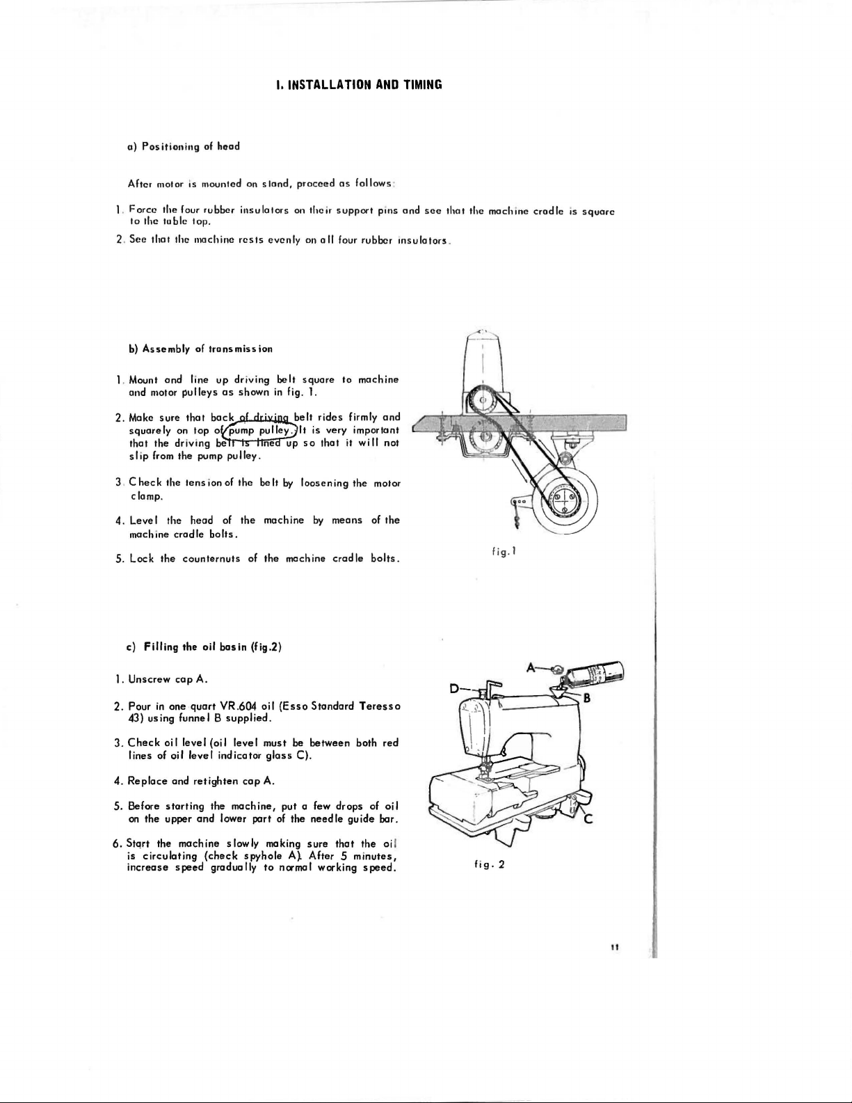
c)
Filling
the
oil
1.
Unscrew
2.
Pour
43)
3.
Check
lines of
4.
Replace
5.
Before
on
cap
in
one
using
funnel B
oil
level (oil
oil
and
starting
the upper
A.
quart
level
retighten
the
and
6. Stqrt the machine
is
circulating
increase
speed
(check
gradually
basin
(fig.2)
VR.604
indicator
oil
(Esso
supplied.
level
must be
glass
cap
A.
machine, put a few drops of
lower port
slowly
making
spyhole
to
Standard
between
C).
of
the
needle
sure
A} After 5
normal working
that
Teressa
both red
guide
the
minutes,
speed.
oil
bar.
oi l
fig.
2
II
Page 9

d)
Assembling
Note
Timing
S 1651 00 for
S 1652
-
2
Prelommary disassembly
- work
-machine
- mach i
3
Setting
Note: The
1 5
mm
seable
-The
needle
-
Insert
place
Set
pin D into
Insert
Attach
the
paint
-The
exact
. Ti
ghten
the
against
-
Adjust
clamp C Tighten
-
Slightly
rotates
-
Set
the
gouge
-
Insert
and
centre
holes
-
Ensure
screw
- Remove
Note : Shou
the
throat
The
gauges
00
cover
arm
ne
arm s i
the
(1/
not
collar
by
the
the
screw
collar
the
set
loosen
gauge
of
the
of
the
that
F,
the
plate
followmg
needle
change
means
of
the
and
and
required :
operations
lor
operallons
plate
cover
de
needle
16")
setting
A over
the
righthand
throat
the
measurement
is
needle
screw
particular
needle
the
gouge
the
tighten
gouge
ld a gouge
of
adjusting
operallons
of :
(the
one
cover
(fig 3) :
bar
on
This
cond
the
sett
must
needle
of
screw
needle
needle
plate
needle
using
X con
H holding
positioned
bar
F so that
screw
screw H sa
plate
corresponding to
machine
or
needles
needles
plate
needle
screw
plate
plate
the
machine
of Sewing
serve
as m log
as
on
fig 7
without
its
uppermost
ition
is
ing.
be
done us ing
bar B and
E
bar
and
and
tighten
and obtain
gauge
be
collar
correctly
it
touches
G.
that
that
in
respect
clomp
is
H
not
be
Parts
to adj
3
the
ool
acquired
RIM
set
tighten
it
the
.S 1651.00
obtained
A,
ensuring
at
the
needle
the
ore
still
to
always
available,
ust
the
tomtng of machi
ondocator
pos
iti
on,
when
63,
No
needle
it
slightly
measurement
from
the
that
the
top
the
needle
clamp
needle
locking
the
needle
tuoching
use
glass)
has a safety
assembling
80,
needles
clamp C on
with
screw
X between
appropriate
ne
.
distance
the
machine
cylinder
H
the
surface
indication
from
and
pin D
of
given in
the
it
is
holding
the
throat
the
machine
therefore
it
tight in
setting
arm of
plate
advi-
and
table
its
.
Setting
the
4
-
Insert
the
flat
-Set
the
shaft
- Ti
-
Obtain
for
(fig 7)
This
Note: The
-
AI
so
and
-
Loosen
Y (fig 3)
-
51 ightly
-Sec
(about
(f
ig
-
The
the
12
ghten
lower looper :
looper
way
surface
eccentroc
looper
runs
the
measurement
obtain
the
that
0.
6)
point
looper
Z in
in
ond then tighten
of
the
B ( fi9
ensuring
as
a tangent to
screw C and
measurement D using
lower
ing
indicated
from
of
is
obtained
the
looper, in
05
mm)
fting
of
the
(lower
or lowering
looper movement
same
can be
the
the
both
the
righthand
port
apply
side
caunternuts A and
toghten
I i
its
holder
looper (fig 3)
that
measurements
righthand
(gauge S
counternut
needle
ion
screw L against
6)
for the evasove
the
mark D on
screw
E of
eccentric
on nut S.
obtained
setting
table
needle
C (fig 7)
1651
s A
its
stroke
scarf
it
slightly
needle mus
of
looper
so
that
it
goes
the
act
ion
the
main
C.
B.
gauge S 01652.00
connecting
from
are
only
measurement Y for
(fig 3)
and
00)
and
C (fig.7)
to the left,
of
the righthand
according
t,
behind
the
appropriate
as
references
rotate
in i
ts
eye)
rod
passes
to nee
downward
when
all
of
the
pin B in
needle
ds
they
indication
and may
distance
one
or
as
close
If
this
and
retighten.
stroke,
meet
(fig. 4).
given
be
changed
between
other
as
possible
is
not
be
fig. 3
in
direction
the
in
line
the
setting
in future modifi
the
point
until
but
without
case,
release
with
the
lower
Z
table
cations
of
the
looper
measurement
touching
screw
edge
of
F
Page 10

SETTING
TABLE
B. 63.
75
75/ ES
B. 63 .
B. 63 . 75
B. 63 .78 H
B 63.
74
B 63.75/ A
- B 63 75
B.
-
I C
B
B. 63 .74/
B.
CE
63
.75/ S - B.
63
.781
HT
ZH
63
.75/
AE
MA
HINE
CLASSES
B 63.751CES - S 63.75
63
7S
I K
- B. 63.75 T
B. 63.781 K
B. 63 .79 I H
B. 63 .75/
AES
CS
- B. 63.75 E
- B. 63 78
B. 63 .75t'
AS
GH
X
12
(I
/
2")
12
,5
(112")
12,5
(112")
12
(I
'
2")
y
3
(1'
8")
3
(I
"
8")
2,5 0,5
(3132"
3 2
(l / 8" )
D
1,5
(I I 16"')
I
(3
64")
1
(I
32")
(5
64")
B. 63.76
B. 63
76/ZH
12
,5
(I
1
2")
2,5
(3132''
(I .
1,5
16
13
")
Page 11

-
If
the
connecting
of
the
stroke
rod 0 (fig
machine
of
till
the
the
fig
looper
is
retarded
7)
must
be
proper pos1 :ion
. 4
or
loosened
is
obtained
advanced,
and,
both inner
holding the
. '
setting
eccentric
screws M of
N in
place
fog . 5
eccentric N of
rotate
the
pulley
-Check
Note
must
S (fig 7) thus varying measurement D
done
modified
Note
to
that
connecting
in
P
of
5
Setting
-
Set
needle
- When
the
-To
6
Setting
Set
-
Set
-
Set
Place
-
that
tangent
eye
(fig
:
be
all
Lock
: When
obtam
eccentric N is
distance
so
that
the
connecting
needle
In
its
deflection
obtain
the
the
the
the
of
the
outside
5)
If
this
is
lengthened
the
settings
except
counternuts
those
the
distance
rod
head
connecting
0 be
it
is
in
rod
of
front
needle
guard Q on looper Z
stroke
to
the
so
that
the
looper point
of
this
condition,
the
feed
feed
the
dogs
dogs
whole
on
assembly
differential
main feed dog D without to
point
of
the
looper,
needle,
not
the
case,
or
shortened
described
given
in
A and C (fig
0 (fig.
rod
7)
centered
care
0 Should on
necessary,
the
left,
the
the
(fig
the
front feed dog A on feed dog holder s lide
bend lubrication
centre,.,of
guard
on looper (fig
the
needle
needle
comes
passes
needle
guard Q
slide
B)
feed dog
on feed dog holding arm
•n
is
1.2
mm
the
I ooper
by
adjusting
If
above
the
first
paragraph.
7)
is
moved in
must be
in
relation
excessive
lubrication
by
means of
guard must touch
close
the
centreline
the
needle
holders
.
ghtening
its
stroke
( 3/
64"
stroke
screw
this
is
must
be
order
taken
to
the
change
tube
hole
0
3)
screws
to
the
of
the
guard to the
it
completely
and
to
the
left,
when
it
is
) above
the
upper
exactly
tangent
of
f ig . 6
R
the
righthand
point
of
lefthand
leit
or right
on feed dog
align feed dog D with feed dog A.
needle
the
looper
needle,
Band tighten
the
holder
and
deflect
latter
screw
E with 2 s
C.
in the
the
E B
must
crews
lefthond
outer need I e
the
lefthand
start
los
ing
H.
f i
g.
7
14 '
'"
Page 12

fi g. 8
A
Centring
-
-Place
- Lock
- Align
- Remove
-
-
-
-Slightly
$etting
-
-Slide
- Counter
-
Setting
-Adjust
Setting
- To
-
Ensure
- Tighten nul R and
7 Mounting
-Mount
needles
-
Secure
-
When
(3/16"}
adjust
and
-Secure
-
If
the
-Adjust
the
Loosen
both
the
moving
tl1e
screws
exactly
screws
Replace
feed
between them,
If
Rotate
Loosen
Tighten
throat
Tighten
rotated-
the
H
the throat
dogs
the
feed
group F and
lack
the
differential
screw
arm L in
set
screw V and
the
height
the
plate;
the
the
stitch
adjust
clockwise
that
and
presserfoot
are
the
the
the
the
move bar B
bar B with
this
regulation
tension
limitation
the
presserfaot with
F
feed dogs (fig.
screws
!~root
entire
G
plate
different
G
main feed dog D
throat
plate
loosen
should touch
screw
V and
the
and
hold
:
af
the
teeth
fixing
length:
stitch
the
feed
plate
the
screws
centre
P
(fig. 8} :
counlernut
slot
in
counlernul
the
should
screw~.
length nul R (fig. 8}
to
shorten
dogs,
screws
move in
dogs
Ieeth
positioning
D on its bar,
centred
presserfaat
tension
opening
assembly
discs
of
the
required amount
screw
is
not
directly
collar E and
8}
:
in i
ts
position
ial group F
Remove feed dog
and, turning
throat
plate
Wand
the
bottom of
the feed
dogs
N
of
sector T until
position
adjusting
N
feed
dogs
so
protrude 1 2 mm.
the
stitch
in
their
W, Z, C
presserfoot
screw
sed
should
lighten
maximum
ensur
C.
about
loosen
one
P,
the
presserfoot (fig
in
the
is
roi
the discs
A.
enough,
and
cenlte
feed dog A si
holder
E and
tighten
the
machine
slots
Should
pulley
the
Z and move segment T
the
throat
throat
(3
:
the
mm
To
A
/ 64").
plate
plate
position
M
are
be
loosened
do not
right
that
and
ing
be
both
in
the
the
right
screw
when they
should
and
anticlockwise
stroke,
0
9}
that
slots
4.5
open.
screw
most
work
screw
in
the
feed
dogs
backwards
slots,
slots
is
obtained
up,
and
to
lengthen
touch
deways
feed dog D ti
direction
touch or
or forwards .
loosen
their
lower
screw S of
it
the
ends
in
screws
of
the
throat
ghtly
of
operation,
hove
edge
the
the
on
too much
P on
is
stitch
throat
plate
holder
make
collar
level
lengthener
plate
slots
E wi
space
Q
with
slots
by
th
the
the
fig.
9
I S
Page 13

8.
Adjusting
-
Ensure
thread holder
- To
H
- When
the cam must
-Secure
-
Thread
thread;
length
9.
Covering
Adjusting
-
The
must
Thread
stretch
the
and
sufficient,
Adjusting
-Set
down,
Insert
the
-
The
left,
thread
A
- Mount thread guide D on
needle
-
The
collar
- When
guide
cam
that
centre
and
sf ide
the
the cam with
make sewing
and
stitch
rear
be
the
take-up
set
cam A
the
looper
looper
point
pass
and
without
clamp holder.
leg
E.
the
must
A.
the
lower looper
the
cam is
land
the
cam,
it
along
looper
starts
start
pulling
the
machine without
the
exact
(top
the
thread
right up.
take-up
take-up
the
is
touching it.
of
spreader)
rear
thread
guide A
B,
thread
for
be further out or back,
B.
loosen
cam
and
so
that
needle
clamp
B in looper holder C
set
all
of looper B ll)Ust,
0.2 to
0.3
must
be
the
thread guide must not protrude
needle
be
about
thread
perfectly
bar
A.
slightly
the
screws
screw C and
bar
main
its
stroke
the
G and
tests
position
toke-up
of
in
its
maximum
about 4
Should
tap
spreader
when the
does
the
way up.
mm
from
as
case
comes
1.5
mm
loosen
shaft
thread.
controlling
of the cam.
:
the
mm
the
needle
not touch the cam.
in
the
as
collar
(1/16"1
take-up cam
screws
.
from
centred
left
to right,
(fig
with
G and
H.
the
top
covering
the
stitch
(fig.ll)
:
covering
(5/32").
loosen
regulation not be
rotate
(fig.12):
and
its
outside
possible
E holding
down,
stroke,
group D.
bar
ensure
stroke
the
away
stitch
must
Should
screw
is
right
to
needle
to cam
from
thread
from
. 10) :
that
the
the
fi
g.
10
E
fig.
11
ftg.
12
-
Set
the
looper
height
sa
looper
passes
SPECIAL
-
The
upper
is
in
the
-
For
two
For
two
-
For
three
needle
. ·
-For
three
the
centre
Note : The
extreme
cause
16
fefthand
sk
behind
INSTRUCTIONS
looper should
following
needle
needle
needle
needle
front thread
ipstitching
positions
machines with 3 5
machines with 3.5
machtnes with 5
machines
needle
.
needle,
that when
the
right
start
with
pulled
nor behind
the
needle
pulling the
:
mm
mm
mm
needle
by
the
the
needle
bar is
thread
under
(9/ 64" )
(9/64")
(3/16")
upper looper must, under no
track
centre
needle
needle
needle
over 5 mm
one
(when
at
its
highest
the
com when
track upwards : between
track
:in
track or under : in
(3/16")
there
point,
the
the
centreline
the
: 0 3
circumstances,
are 3
needles),
point
mm
the
thread pulled
of
the
needles
of
the
centreline
(1/64")
pass
because
by
the
the lower looper
centre
needle.
of
the
centre
to the right
behind
of
the
this would
Page 14

10
Ad,u
•
•
· Mount
·
·
s ll
ng
lnsorl
plate
suoloce
Secure
D
Ensure
cull
ing
Loosen
ri
ghthond
• Toghten
tho
knive~
tho
foxed lower knofo A
the
knife with
upper knif
that
edge
screw
needle
screw
(fig
(oboul
e C sliding il i
the
poonl
of
the
lowe
E,
adjust
mov i
E
0 I
screw
ol
ng
13)
·
on
ols
mm
• 0 2 nun)
holder
B
nto
the
groove
the
upper knife, when il is
r kni fe
the
trimmi
ng
the
whole
so
group
thai
and
on
the
the
cui
keep
upper
tho
knife
ol its
lowest
is mode on
culling
holde
the
edge sli
r rod
and
point, is I
fabri c on
ghtly
secure
mm
the
below
il with
(1
/ 42")
centreline
the
below
throat
screw
the
of
the
E
fig.t3
17
Page 15

a)
Thread
'
ong
11.
USE
THREADING
2 N
EEDLES
Page 16

•
'
•
'
•
'
•
•
'
~~
\
•
\
•
\
.f'k
)i'>
" f
THREADING
10
3 NEEDLES
Page 17

b) Changing
1. T l.lrn
2.
Depress
3.
Toke
4.
Loosen
5.
Remove
6.
Insert
7.
The
8.
Using
9.
Tighten
10.
Do
c)
Adjusting
1.
Check
2.
The
3. To
d)
Adjusting
1.
Tighten
for
tightened
off
the
the
the
needle
the
the
the
needle
the
the
not
exert
the
needles
increase
the
the
lower looper
the
needle
motor.
motor
to
needle
needle.
new
needle.
scarf
tweezers
needle
too much
the
presserfopt
correct
must
or
lessen
the
tensions
tensions
as
required.
pedal
its
highest
holding
for
the
supplied,
holding
pressure
setting
pass
the
sufficiently
is
:
to
ensure
screw
passage
screw
of
through
pressure
:
left
that
point.
by
of
ensure
taking
when
pressure
the
presserfoot.
the
to give o
entirely
the
1/2
o turn with
the
looper
that
th~
core
tightening
:
centre
of
the
loose,
machine
of
presserfoot,
regular
is
must
needle
not to move the
the
the
slots
stitch
and only
completely
screwdriver
be towards
rests
screw.
in
the
turn knob D (fig.2) .
formation.
the
small
the
against
needle.
presserfoot
stopped.
1161 / 2.
the
tension,
rear
of
bottom of
.
In
most
on
the
cases,
the
machine
the
hole
the
take-up
.
.
thread
cam
tension
plate,
is
e)
Variation of
Loosen
1.
2.
Rotate
to I engthen it.
3.
Retighten
nut R
screwS
nut
stitch
using
of the
R.
length (fig.
the
proper
stitch
8}
:
spanner
lengthener;
rotating
it
clockwise
to shorten
the
stitch
and
onticlockwise
21
Page 18

f)
Irregularities
due
to
improper handling of
machine
.
n
Irregular
1
2
Feed
sideways
3
Skipstitching
4
Thread
IRREGULARITY
stitch
and fabric
breakage
slipping
PROBABLE
-Tensions
-
Thread
- Incorrect thread ing
- Yarns not gouged
-
Insufficient
-
Feed
· Differential badly
. Lower or upper looper badly
- Front
-
Needle
- Lower looper take-up com badly
badly
toke-ups badly
dogs
needle
badly
adjusted
presserfoot
badly
guard too far away
positioned
adjusted
adjusted
adjusted
pressure
in height and
adjusted
-
-Tensions
- Yarn irregularly wound
too
taut
on
cone
CAUSES
in
from
needles
adjusted
slant
respect
to
needle
5
6
7
8
Needle
Punctunng
Oil
Lack
breakage -
of fabric
leakage
of
lubrication -
Needle
Od
needle
level
bent
w1th
tao
unsuitable
suitable
base
gasket
mach~ne
low
filter
- Needle badly mounted
- Blunt
- Needle gouge not
- Needle
- Screws joining
- Oil recovery
- S1de cover on
- V - belt incorrectly mounted
- Lubricat1on pump
for throat
point
and pump not ti
in oil pump, not
arm not tight enough
clogged
ght
plate
centred
Page 19

a)
Every day
I
Clean
2 Check the oi I level
I
2 Check
I Us mg the correct
2 Unscrew pin 633-979 fixed to
3 Remove the fi Iter
4
5
6
7 Re-fill the machine
the feed and stitch format i
b)
Every week
Di
smaunt the throat
the
oil level
c)
Every three months
With
compressed air,
Soak the felt pad in
Replace
In
most of
the
operation I
the
oil con drain
plug
of
paragraph
plate
and
and
if
spanner
and
clean
blow the filter
clean
w1th
a quart (580
from
necessary
remove the plug and drain out all
oil
Ill.
MAINTENANCE
on
elements bri
clean
the feed dogs, loopers
add oil
the
inside
it
in
petrol
and
gr)
IMPORTANT
C,
be careful not to unscrew the drain plug
the
side
holes
efly
of the drain plug
replace
it on the drain plug with pin 633-979
of
Esso
Standard
of
the
plug
and
the
Teressa
itself
feed
oi
(fig
elements
I
Oil
14)
43
(VR
.604).
completely
at
once
so
that
fig . 15
Assembling
d)
I
Place
2.
Insert
lower port of
3.
Position
603-248
4 Mount
5.
Replace
6. Mount
the
the
the
the
the
oil
machine
two
threaded
the
machine.
the
oil
and
oil basin with
the
drain plug
basin
rubber band
positioning
basin
(fig. 15)
as
shown in fig 15
pins
270-963
(without
633-212/1)
the
respective
pins
with the two remaining
in
the
the
plug G.633-981
using
the
screws,
·I
two
above
without
holes
pins
screws
diametrically
and
complete with
as
a guide.
tightening
and tighten all
opposite
them
completely.
to
felt
pod 633-829,
screws.
one
another
in the
gasket
23
Page 20

SPARE
PARTS
CATALOGUE
/
25
Page 21

a)
INTRODUCTION
1.
The
spare
wh
ich
make
2.
In
order
inside
the
The
conversion
3.
4.
The
subclass
basic
machine
5.
In
each
whose
components
6.
The
co tal ague
numbers.
numbers .
parts
catalogue
up the two
to
facilitate
machine
table
These
.
groups
number i s given in
from
which
the
various
cannot
has
o general index givi
ore
cross-referenced
compri
bas
ic machi
the
use
of this
of
the
it
is
parts illustrated
be
supplied
I.
HOW
ses a series
nes
and
catalogue,
bas
ic mach i
the
top righthand
derived
.
separately,
with
II.
TO
USE
the
ng
the
HOW
THIS
of
tables illustrat
ir
subclasses
the i
ne
and
ore
cross-referenced
ore
all
the
ports
table
TO
ORDER
CATALOGUE
ing
the
.
ndex
of
tables
its
subclasses
corner
of
each
cross-referenced with o capital
in numerical
number
where
various
shows
ore
table,
with a number.
order
they
parts
the
illustrated
and
in
according
ore
shown
or groups
position
in
separate
brackets
The
letter
ond
of
group
.
to
their
their
of
each
beside
of
drowil'lg
reference
parts
group
tables.
it
the
parts,
o)
ALL
In
order
rules
be
1.
Indicate
2.
Indicate
3. Write in
Clearly
5.
Messrs.
produced
parts.
b)
NEEDLES
I.
RIM.
63
2.
The
needle
3.
The
gouge
blade
of
4.
The
system
5. When
6.
7.
ordering
(example : \00
In
case
attached
For
sewing
SKU.
PARTS
to
ensure
carried
uot
machine
drawing
full
state
Rimoldi
straight
the
of doubt, a
to the
number
the
description
the
desire
by them. For
needles
system
indicates
needle
and
gauge
needles,
needles,
order
on
elastic
that
:
serial
quantity
and
gouge
the
.
ore
sample
.
material
the
correct
number.
of
part
of
required
to be
this
reason
must
are
average
also pri
it
is
gouge
needle
parts
required.
the
part
.
able
to
analyse
please
be mounted
marked on
diameter
nted
on
advisable
90,
system
as
or
elosticised
are
despatched
requi red.
IMPORTANT
any
ensure
on
the
the
expressed
the
envelopes
to
clearly
RIM.
well
as
case
that
machines
needle
state
63).
an
empty
materials
I
immediately,
of
breakage,
these
illustrated
shank
.
in
hundredths
of
Rimoldi
the
system
envelope
needles
it
wear
parts
ore
in
of a millimetre
needles
and
of
with
ball
is
or
sent
this
.
gauge
the
points
essential
irregularity
with
catalogue
of
desired
exist,
that
found on
the
order
.
calculated
the
needle
needles
classified
the following
parts
for
spare
on
the
requ ired
should
be
as
27
Page 22

IN
DICE
63.
75 Tav. I
63.78
DELLE
II
T A V
OLE
Albero
con
ta
Albero
barra
Albero
barra
tura
Albero
dino -apertura
prtncipale
bielle
grtrra
superiore
ago -
superiore
ago -
saperiore
comando
-
con
copertura
senza
tnr.
gruppo
differenz.
comando
comando
coper-
alza
tenstoni
por-
63.75
sup,
63. 78/H Tav. 3
63.75
63.78/H
pie-
Tav. 2
Tav. 4
Albero e bielle
crochet
M
ovimento
filatori
inferiore
coltelli
comando
ri-
63.75
63.78/11
63.
75 Tav. 6
63.78/11
Tav. 5
/
29
Page 23

Uacinella
tubctti
brific.-copertura
con
e
stoppini
pompa
olio,
di
super.
lu-
63.75
Tav.
1
Oacinella
tubetti
brif,
Coperchi e piano
ro -con
Coperchi e piano
ro -seoza
Passafili
copertura
e
senza
copertura
con
pompa
stoppini
copertura
copertura
e
teodifili
auperiore
di
di
olio,
di
lusup,
lavo-
super.
lavo-
sup.
con
63.78/11
63.75
63.78/H
63.
75
63.
78/H
Tav.
Tav.
Tav.
Tav.
8
9
11
•
Passafili
senza
Portabobine,
coaando
Acct!ss
30
e
copertura
alza
ori
tendifili
superiore
pedalina,
piedino
:~:~:/H
leva
63.75
63.78/
H
Tav.
Tav.
13
.J..
14
-=
(
=if==r
~
~
~
•
Page 24

Classe
B.
63.
74
Tav.
15
Classe
8,63.79/U
Tav.
35
Classe
Classe
Classe
Classe
Classe
Classe
Classe
Classe
Classe
Classe
Classe
8.63.74/ZH
8.63.75
8.63.75/A
8.63.75/AE
8.63.75/AES
B.63.7'J/AS
63.75/C
~·
8,63.75/CE
8.63.75/CES
8.63.75/CS
8.63.65/E
Tav. 16
17
Tav.
Tav.
18
19
Tav.
20
Tav.
21
Tav.
Tav. 22
Tav. 23
Tav.
24
Tav. 25
Tav. 26
Tavola
Tavola
Tavola
Tavola
Tavola
pezzi
pezzi
Kinocchiello
tagllatore
ta~~:liatore
TE
11
tagliatore
TE
11
a
richiesta
a
richiesta
per
K
Tav.
Tav.
Tav.
Tav.
Tav.
36
37
38
39
40
Classe
Classe
Classe
Classe
Classe
Cla~se
Classe
Classe
8.63.75/ES
8.63.75/S
8.63.75/K
8.63.76
8.63.76/ZH
8,63.78/QH
8.63.78/H
8.63.78/K
Tav.
27
Tav. 28
Tav. 29
Tav.
30
31
Tav.
Tav.
32
Tav.
33
Tav. 34
/
31
Page 25

B.63.75
8.63.78/11
70
63
I
IS
62
18
71
77
1
N'
1UF,
1
2 0 0
J
4
I
•
1
I
I 0 I
IO
1 I 0 1 1
If
,,
,.
1!1
''
17
II
II
fO
II
12
IS
,.
,,
J:l
,,,
II
tt
)0
31
,,
SJ
34
,,
31
J7
,.
Jt
AD
4 I
,.,.
41
..
N•
OISEGNO
01
'-
t
••
....
'.,
00
I
.c
• I 0
DO
J.
A.
4.
OOA
.c
..
7
00<4.,_.
OOI
..
G.II
007.M
..
II
I.
[ .. I
011
.. t
•••
.l
.. 7
0 I
7..,'
.. A
011
.. £ .. 1
031
.. 0 ..
10
OIO.,L
.. I
o••-•-•·'
Z7D
..
t71
3lD.lOI
103.011
IOS.OIJ
I~U.OJI
103
..
040
IDS.OC.
103.041
103.041/1
11103.117
101.2111
003
..
211
10).111
50).112
13.71
..
114
IOJ.tfA
103.111
IOI.SOO
IOS.J
10
101.1'1:0
IOJ
..
lZZ
IOI
..
tte
103.174
IOJ.fll
f'M.
131.ZSII
ItO
.o
I
II
azo
..
o••
IIO.IZA
,,,_,,,
5
s
I
DENOMINAZIONE
I'ITt
P[lt
I:AMMA
[p
't
I 1 t C I
LIND
'WI 1 l C I L I
I'ITL
"'''
¥1ft
YIIC rl.l.
'fiT[
••AMO
&II
OIIAMO
GIIAMO
oa~oMo
Yl1l
0
110
'fffl
OAII
PIING
P[IIMO
11:110111 OC:l.
SUPP01110
OU&SOl.A
L[Yl1TA
1\.
lrf11
YITC A lllill11110
PIAITIIIMA
PIA11111fA
CUIIIOIII
O
•
Yl11
OUIIO\A
SOUAOOl11A
AMlLLO
AMllLO
oo•or
'f
SPINA
11MOITILO
MAIIIIC0110
lCCEMfllfCO
AfTACCO
IUAIIMtJIOMt
....
CILIMDitiCA
cn.••oalcA
CILINOJIICA
.l
fiiSA 1>[1101111:
ff U11
AMO
r I L
11 TAt
ffLI:11A10
flllf1A10
rtLl11AfO
tfi
i A
AO
0 I
ItO
I
l.l
A I
ffiSA
fA A IU\.L I I
Pt:ll
P[ll
01Cfl1AM1[.
Pll
Pill
f 1 t A p
Oil
PillA
I
Pllll
OUA011.11A
ouaoart1A
fii
i A
Pll
01
O f
u.,.
Pll
t 1 I r I 1 1 A t
P l l
COMAMOO
[CC-CfiDCIIlT
It
I ( A I
I
C:
A
Pta
S l T T OJI ( I
Pl:lt
tLAitGIA
ll11011S:
ATTACCD
OtA~CIO
GtUMTO
Olft[I[MlfAl.l
Olftfii[Nl'f&lS:
1 A
,I.
Pl.ll
Pill
OlffiiiiNl'IALl
POITA
PoatA
OUo~>
Ll.'fi11'A
OIL
111,111110
lllOI0100
VIs
OIIACCIO
A
CAMMA
PlO
Al.lA
Pll
riSIAG,Oitlrr
Of
A10
L l
ClIff
IIUAOIIL11A
cuoso111
LAIEIO
lfl.AifCIAM
0 p l
II
AM
r L l I J
POII1,_
GltlftA
POIITA
GlfffA
'fi11A
OffPIIIIMJ,
A I
Plll
Of
Pll
01.\
llt:SflfiiO
Pill
PLa
Ll'fl1TA
Offfllll
otrr••
llllffA
CII0CMI1
PatMCIPALl
OlllffA
Olff
'flfl
DffflllllfiiALl
OllffA
cotrra
OLA
IHffllllMJIALI
0 I I
POITA
Pl:l
OlllfffA
POOTA
fLAMAIA
, 4
, •
131.71
IJ
. J 1
. I
· 1
tNt
N'
i
i!
RIF
. ,
120.7011
4
• • 1 311
4 1 I
... lt0.707/t
t
••
1
z
10
ItO
t
12
5 I
l
It tll.
Ill 1311.0
J
, .. 1
s1 tJ.71.r
I
•• 111.217
J
1'7 ISJ
•
••
1 1 .
I
••
1
10
0 3131.
It IS3,
t
ll
• • 3 . •
II
J J O .
t
'"'
..... tto_,,
t
II
PM
I
•• PM. I l 3 .
t
OJ
PM,II I ,
I
Gl
G , IJJ.I
I
II
G , 113 1 , 0 1
'70
G.
71 G,IIS
1
71 ...
I
71
110.701
1
74 ZS0
I
75
1 2
I
Jl 11.11.041
77 G,6J.7
I
71
••
71
.,.
I
tO PM.IJ.78.3t•
I
•• •s.7t.tll
1
12
J70.7t3
11
Dll C.l
... 11.'71
J
II
01
81 IS.71.0
17
·~t.71.1
•• 210.11
at
OIO.
N
DISEGNO
.010
II.'Ztt
to
. t t 2
.Il
l
1.
00
I
OOO
41
)3.
0<fo
3
J7
.II
t
71.111
1~.
510
117
t55
10
JO.
.. 1:11 OIJ/1
2tl
IIS
II
01
1.04
. 2 1 7
.. 31.515/1
.704
0.11
1
1 . t
,,_,,.
_._
,
... 711
,71.70
5S
23
l
p .
tt.S
IIULLINI
OUI&OLA
1 L
Gil
Y
YITI:
ALIItiiO A COMITO
't'Ol.aMTIMO
P[IIIIO
•••ccao
Ylfr rt
PlOMO
lli
P I
OCC
IIOHOtL~A
IIONO.LLA
OIIAMO I'l l
GIUNTO
,
LCfA
tLAMGIA
/Z
1l lo1 A II I I
1111ANT[ CDMPLt:TO
7/1
Ill~···
1
e:aurro
ltCtMTIIICO
OltllA
OAOIIJ
ANILLO Ol
,
ICCllf1111CO
Of
,.ll
1
.....
1 I 1 1 A 0 I 0
of
1101t11
OAO
oONOrlLA S
1
GAO
l t C I
GlAND
VIIAMO A PUNTA
Y I 1 I P l
AltO
AN
I 1 f P f
i-O
ING
..
ll.1TOIIC.
..
UWTO
t L L A
Ill
ANT
UNTO
O
O I
Pflll
PtO
t A
I MA
f<l
It 0 11'
II
I I ILL A
Pll
01
1'111
IUfPOMTO
ro11tA
s • a
StOIIItYOLI
OLA
COM
CON
A1'1AC(0
IO
O f
IIIILLA
Of
Prll
Pfll
YOlAMTINO
COMPLC10
COMANOO
CON
IlL
L I
YA
o t
rrrarNrt
PllllfCIPALC
I T T A A
Tt:MUTA
COII.MOYIII.C0\.1[LLI
I
IlL
A I
LAST
PALLAiiltHtO
ITTA IIULLIMI
NT
II
I C 0
.It
II
I I
OENOMINAIIONE
Of[LLA
COM.ALO.IUP.
ALII
110
0
PI
I M C I
~\.
~ A
PIIIMt.tPAl
OSC1LlaN11
Gof
rra
SOUAOIIf11A
IAT1U1A
OILAMCIAMtNTO
ALitiO
PIIIMCtfALt
Pro•o
ICOIII('fOLI
Ptll
lCC[MTIIICt
POOTA
GOiffA
OUJIDlA
LA
tOMAMOO
ALl
ALLUN.A
PUM10
CO-fL[fA
IIULLI
OlL
CIIOC"IT
LA
tCA
I I
COL
1 t: L L I
tl.
LA
PAL
>o
'
.
II
l.
lllf,
'
•
•
'
I
'
I
I
I
I
I
I
.
I
I
•
I
I
I
I
I
I
I
I
I
•
Page 26

8.63.75
2
r
7
~------------v~----------~
76
21
N"
RIF. DISEGNO
I 0
I D
t o ost
I I 0 7 I . G .. I
I
I 0 l I .. C
.,
14 Ott
II 011
II 011 .. 1
,, 011
II OtJ
It
20 ''"·'
I I I I 0 ..
I I J
2 J I
z•
I I
II
27
II
II
311 II l ..
3 I lli
II tJJ.OIS
IS
'.
J I
II tlt
,,
.Jt
It
40 ltJ
., 111 . 1
.t I
.. , IJJ
•• lll
41
4 I
._,
4 I
.........
10
00
I.
I
0 I
0 I
l. a .I,
oot.o
oo•
DD4.N.I
0 1 I
IJ
Jt
o tz:
RG
••
lO
70
r7o
170
tlo
IOJ
IOJ.Jl8/t
IOJ.Il
I» I ..
.
....
Il
l.
111
I.JJ
8JJ
10
I .. t
111
II
I .. I I
II
. .. t
II
t
111
C:
..
A
. r
.C.
..
t
.. N ..
.G
..
l
.. I ..
.. 1 ..
..
1 .. 1
.. C ..
47
.. 0 S I
.. l I I
..
t t l
..
1.7
.. t
.. lll/
01
..
D I I
I 0 I
,
I I 5
.. I
.. 1 0 1
.. tlO
..
I:I
..
tll
..
t l l
..
t f
.. 110
..
I I !I
..
111
N•
.l,
..
I , t
. a
..
•
:1,
..
S,
I
..
I
..
I
..
t
J
4
..
1
I
4 •
'"
I
1
lt
l
4/
..
04/I
•
11/1
It
l/1
I/I
l.
Ill
5
• 1 T t •
C I
I
CIA
Vlll
Y I
'f
a a A
I
IIAIIO
I
\'IT l 1'
DAIO
IOIItlLLA
IOIIDILLA
C:ILUIOIITTO
CILIIItatTTI
CI~IIIOIL1'TO
CILIIIOilTTO
CIL111Dit110
I
~
51
\'ITr
\'I
OUIIILIIIA
lllllllLA
IIIIOtLLA
\'l~
\'ttl Pll
IIUIITO
1
.
....
II
I
L~\'A
MOl
•
a U
P I I
ATTACCO
tiLT
CAITIIIIII
AITI
Lt\'ITTA
/t
PAIIAf
a•taar
f'AIIAfiLI f't:l IIOCNtT
/1
'"'''
Ll\'A
ILICCNlTTI
••
IU
f l
LI\'11'1A
....
11
1 T
II
I e P
ll
flO
rILl
P'll
llYlffA
'f
I J' 1 t I
11
II
I r I L
r1Ll1'1A1'1
C •t A l 1
f'l:l
f'll
f'll fAI.
Pll
Ct.trt
T t
Pll
Pll
Ptl
t
Pll
PIITA
LI
f'll
,
....
l
PIITA
l O
POITA
• • · r r •
\'A
all
Ill
A Y
COMAIIOO lAl
I I
·IIA POI TA T I
TIIAflll
ILO A CAll•
ILl
,,
...
Cltl
111\'lti.Cif'IIT.IA
..
soLa
tttrr:atoar Plfl
I I
ILA
IICILLAITI
tlt
f'll
tl
,.
,,.
1o
A P A I I
tt
1'AIC.l11A
f i
AlltLLO
IT
Pll
OIIIIILA
t T I r I
TOPPIIII
TOPPIIIO rt~
IT
••
DENOMINAIIONE
"r
r" I
r A 1
C:
f T
1'
A I
T
1'
AT
0 I
li"DifllO
PA
ll
t1
A J
ll
0 I
Af I 11
t
A1'
I Z
rt
, I A
0
II
tlTTA
10
Pll
Pll
1\'A
CIICIItT
Mrltollt
a
,
f'ltlll
ALI
IIUIITO
lAllA
ca•alltl
f'OITA
lA
..
,
..
,,
CtM.ICIOCIIIT
I 1
CILLA11't
MOIIITTO
1'111011'
IVf'tt.
'"'·
a.aTa.
AI
ILiro
r t l 1
flL1'11
rtLTIO
flLTII
1'111'10
LTII
TIO
Pll
OIUIITO
Pllll
~
WA
CIIIAIIII
AITIMA
,.
Pltlll A lf[IA
AIMI
••
111
l
II
PIOTtllllll
1111111'TI
,
...
f'll
MOWt•r:tTI
··~······
N'
~
~
RIF.
DISEGNO
IJJ.J17
1·1
Ill 1 ..
IS
II
..
..
I
II
..
I
n
..
I
I
••
t
••
II
I
•
••
••
..
••
II
17
..
..
70
71
71
71
7A
70
70
77
Ill
70
70
••
..
..
••
••
..
..
17
a
•
I
<
D
•
r
.
•
L
M
1/1
II
J .. I I
4/1
llll
..
lll
II I ..
70
4
UI
..
71D/I
I J J .. 1 I I
Ill.
t I I
Ill
J
..
t J 4
........
.......
l
IIJ
..
t41
IJJ
..
tll
.
,,_
..
,
I I
J.tiO
IIJ
.. t II
,,,.,,,.
II
I .. t
17
II
J
..
t I I
G.
IJJ.,OIS
PM.
Ill
..
80111
..
014/1
PM.
IJJ
..
o.
111
..
114
G.
111
..
111
••
111
..
177
o.
111
..
114/1
a.
tss
..
T 1 1
••
111
..
111
110.,710
II
I .
101/1
111
..
771
..
.......
111
..
700
Ill
..
701
PM .
111
..
....
111
..
'·
........
PM.
IJI
..
IJ
1 .. J I I
..
. _,,,
IJ
J ., J
JO
I
JJ
.,0
II
IIJ.,OI7/I
1
11
..
0 1 1
..........
........
,,,
111
.. 141
.........
lOS
tlt/1
141
017/1
IJJ
,,
,,,
.
AIIILLO
raacrtTA
...
..
a.~otao
e" •c
IIIITTA
rattl1'1A
,
..
,,.
oaoo
Y I I l
GIAIO tll
\'11'1
IO.IILLA
IO.IlLLA
IOIOILLA
\'ITI rlt
Y l
1r , ••••
Yl1'1
\'11'1 tii
lAllA
C
Al1'
LIYA I IIILLA
IIVrro
IIVf'PO
LIWA I IIU.11
talrf't
111111111
tAtCIT1'A
•rAI
CITTA
\'ITI
liT
Ar
,,.
t
•rt
I
IlLLA
a•rLLI
••a.•••
c••••
IIUMtt
ALIIII A IIIWIIIITI
t.rwa
LI\'A
rti1A
r1111
PLIII
••••••
Pllle
Stll.t.
ca•••
I •
.I
aLIIte
DENOMINAIIONE
co•&•ae
rrt
•••••
,,.
,,
...
c••••••
t•tTTI
A
IVLt.l
ILAS1'1CA
f'OITIIIOi
,, .......... ,
'''
rr•••
tA
LIYITTA
rlt
i A
AIMI
f'll
ALIIIO
f'll
Alllll
tA
CIICMIT
,,
....... , ••••
Pll
fAtC.ITTA
iA
ILICC.Ml1'TI
All
CO.f'LI1'A
II
rttiA
r A
1 a
c••
c••••••
CI.AIIO
CI0Cifl1' s•PIIIII
Pll
I.PIIIOI
t•rriiOi
PLI
lL
a
LI\'A
IUIIILA
TlltlriLI
lLAtTICI
r
••••
Ill
Pc•
.t.
CIIIAiflt
''''"
f'IITIIIIIl
COMPLSTA
CA.IIA
11rc
••
lAllA
raa
PIITA
•owiii£1
•••
ca•••
•a•owaLLA
CIIIAIII
CIIIA.II
I r 1 1
• • a a o
l
1lllltiLI
"'"'
•••••
Pll
•••••
CIIIA.II
CIICII1'
••••
All
t a
T O
Pll
•••
•••
Ptll
t
f'll
.....
••o
CIIIAIII
COMa•eo
.....
ALIIIO
CIOCIIIT
CIICMI1'
c•••L•••
Cl.
Pll
lAllA
COIPLI1'1
ct•rLtTI
ceoc•c•
ClllllT
I
CIICifl1
lAllA
lAllA
PIIWI
,
CIICifl
r 1
l
.
11~.
1111
All
AlP
I
I
I
I
I
l
I
I
I
I
I
I
I
I
I
I
I
I
I
I
I
I
I
I
f
I
All
Page 27

0.63.78/H
3
N'
DISEGNO
RIF.
I 0 1
7.
A.
I 0 1 1 .
1.1
J
tlt.NI.I
•
D?I.C.I
I
···
·-·
....
..
•
...
_,,,
7
I
IJ
I .. 0
I I J . 0 I I
I 0 1 1 1 .. 0
'
1 1 1 .. 0
II
,,,_.,,
..
,,,
_,
II
.. ,
......
II
Ill.
"
II
1 7
II
II
to
II
II
.,
..
"
II
lSI
IIJ. J
.
......
IJ
J . &
IS
J . 7
IJ
J . 7 1
I J J • l t I
I J J • I I I
I J J .. I :l4 II
..
,_
..
I I I
..
t i l
111.111
N"
2,
f
. 1
-·
.....
14/1
11
11
,,
..
II/
l
..
,.
II
G4
0/I
,
.,,,.,
,
.....
.,,,,
Y
If
I
.
...
.
.....
,
.....
,,.,.,
....
.,,,,
LtYA
......
...
,,
...
.
..
.....
,
...
·-
··
...
''"'"'
.....
' .
•
1.1
..
0
.
&T T ACC
0
CUll
A
t
II.
WIIIIIITTO
Al.lllll
co•.••••a
CUICitf[TTO
IOtiTTA I I.
, ... c'
1''
...
1'
,.,
, •
o\'11
I
...
wIT
I
, ' .
•
1a1
I L L A
aOMOtLLA
D!NOMINAZIONE
P A I I A I I L 1
.......
.....
III
I I
I
AI
I a
.,,,,
c ........ t
0
.....
lllll.
.
A l
TIc
,,
..
.,
.
&&
HI
..
...
...
..
.
,,.
••
0
..
...
A
IN
I
...
L I
A
.....
N'
RIF.
~
.,
..
I
JO
..
..
..
..
Jl
..
ac
M I
J7
..
..
"
..
"
••
..
••
..
.,
..
A
.
N'
DISEGNO
. ,,_
....
.
'''·'''
'••.
•z
•
1.11
..
11111
Ill
.. 7 I 7
50 I I J .. 0 l
G ,
IJJ
..
OI4/I
..
,,,_.,.,,
Q .
,,,
..
711
• •
111
..
717
110.710
.
111
..
111/1
111
..
144/1
,,,_,
..
•••-••o
G.
ISS
..
SIS/I
D I
I.A
..
lo
,,,_,,,
a.,ae.ssr
P'M.
Ill.
14
..... IJS.Oil/1
o. , ••
_,.,
........
IJJ
..
JAl
!I
I
1
,,,,
1'
I
...
.,,,,
....
••zzo
'a
tc
lT
T 1
P A
IC
11'.
A
ACCOI'I'IAIIIIITI
L I
VA
I I I
.....
,,,.
rAte
tT
1'
a
r A I C I
f'T
A
~ ,.,
Y I
1'
I
c
.....
IIIII
A
.
..
..
,
.....
I
IIOMOll.I.A
t I
ll.l.
A
.....
...
11
II,
11
11:
T T A .
,
......
,.,,
...
c.••••
l t
U•TI
...
AL t 110
.
ALI
tao
.
•• I IOL
A
DENOMINAZIONE
I I
IL
I
,
..
AI
II I
...
.
......
...
......
Ltl'A
IlIA
.....
.....
..
c
.....
Co\WMA
LA
I Y I
CO
r
&S
CIT
T A I A
..
tAlC
CO
..
Plll"TA
.,
.....
...
..
•aMeWILL&
•aMOtiLLA
...
...
&IUMTI
......
1111
A
.
..
I A
...
1111
A
...
ll"T T A I
...
l
.I
'
'
'
I
'
'
I
'
I
I
I
I
I
I
I
I
I
I
I
I
I
I
Page 28

13
r
1 /
lllf
26
29
9
~
-
~
--
----3
s-----15
~
17
/ 30
2
8.63.75
8.63.78/H
4
35
~
-N~
olseGNo
_
:::·:·-,
---
...1..
~
~
:;
:.
=:.
• •
"-'
' ...
: : :
:
!
.
.
:
-• · • ' " ' •"
:u
:::;
:
;:::::
: :
:!!:m
...
...
m_,,,.. , ..
,....
..
........
l
I
.
I
-.
. ::: ; : = . . .
:::: : , .
::::
:::·
m
:.
:::···
:.·.:·:::
·""
..
...
.........
DENOMINAIIONE
~~r----
..
. . .
.
-:--
'"""'
..
~
.:
:·::.: .:·::::. .... : " , .. -... l
:::
....
::.:.
:::
-~:
''
:;;,:::
.·
·"
•:::
...
·:::
.. " .......
....
:::::. : ::
,,,
........
:.::
~TI~
" '-'" '"'
";:.: ...
''
·':
:::::.. : :: :::::::" : :::·::.
:
;~:='
;,
.....
:. . : :::::::··
·..
.,
::·
..
'"
~AMf[
~=-
rg~~11
....
,, . ,,
..
. : n m
,......
.
......
I I I
~
IR~;,
:
:: .::::::'.
· " ,
'
..
: ::
I
35
N'
I
rr:
DiiS
f
E
i
G~NO~-l~~:i":i~;;~~~~~-====~rj
"""'
.......
'"·
.. :.········ ::
:m:.::r,~:::·i:
.....
. '
.....
''''"'
L<VA GLI
co•••
.....
......
:·
..........
. :::·::.::
A
'•••
:.·~!:•,
,,.,..
...
,
..
.::-:::
.·M.,
I
:m
:.::
_...
U.
UI/
IOS.A
IO
:m,,.,,:;:::•
...
.
1
I
I I
"~'""••
..
·:
:;.;:
.::::
,,
OLLA
N ° I
....... ... :
[\'A ALI A
'.. -;-
.,;
·'"'
·······
:"•
:'""'·
. . .
..
......
...
.....
... ;::::
I c
0
:
'
'
:
'
: •
I
:
I
I
Page 29

8.63.75
8.63.78/11
5
,..
RIF
,
I
oo•~•-~·•
0 t 0 .. D .. I I 01
.
0 I 0
'
01
•
0
•
01 7 .. [.I , I
•
,
0
.
O
:llt .. H ..
0 1 t
•
. ,._,_,
I 0
OIO
II
014
DIS
"
..
oao
"
IO
..
..
10
1 7
10
,.
IOS.OI
1 0 10!
..
IOJ,.OI
IOJ.Oit
101.070
"
l OS
"
10 S ..
..
"
..
10
,..
DISEGNO
..
H .. I
:II
I .. G .. I 0
17
..
[ .. 4 • I y
II
.. t
..
I
I
.a
..
I
.. t
..
t
.. L .. I
.C.
I
.. [ ..
t
S .. O
!S
J
..
0.
J
J .. 0 I ..
S
.01
1
I
., lit
I l l
J.
I I I
,..
DENOMINAIIONE
..
,
rrwsA
\'IT'VITI:
...
• 7
...
"'''-
Vll
l r I I I A ·
IT
I.
...
.,,,
.
...
.,,,
.
...
...
'li
T I
.....
. "
....
..
.
...
.
...
....
,
.....
IlOilO
ILL
tONOII:LLA
.,
...
I
UPPORTO
•
ltlt
0
sUPPOIII
, .
....
....
,
...
..
,
...
IHIII:IIIA
.
.....
...
If"
I M A
IIIIACCIO
....
I I
IE
L I. A
tilL\.
I'
tIll
I M I I I A
I
UP P OtT
c M I
1:
t A
Ll'IA
TIIUITl
. P I
liMO
TIIANtt
...
.
...
A
......
0 I ,
....
..
.
.IUM
...
P
...
I
UPPOtTO
? O
Cit.L.AIITI
O I
.......
,
CtOCMIT
...
COMO
...
co•o
I
I'
I II A
f I L t T
TAT
...
llYA
A
COMA
0
C:
oM
0
CDIIIICA
DIP
.......
...
f O
01
T A
..
.
HI r ll
A
NOD
I C A
I'
I o
CROCHIT
,
...
.
I I II
I I
1:
CAOCMI:f
IL.
LA
,;
~
8
RIF
17
"
..
..
••
I I
..
..
..
..
..
,
..
••
..
41
. '
13
••
••
••
47
••
..
,
IOJ.JJI
••
IOJ
10
10
IOJ
110
IJ
IJJ
IIJ
ll
ISS.I.I/1
ISS.ttl
ISI.SIS
IJI.SI6
rN.
PM. IJJ
rM.
o.
G .
o.
AI.
.,,_,,,
111
N'
DISEGHO
a_,
• •
..
7J6
J .. I I I
J .. I
II
..
tlt
..
707/1
1 .. ,
...
..
7DJ
..
JIJ
J .. 7
14/1
llO.!tl
IOS
COJ.Oit
IIO.Jtl
111
..
011/1
ISI,.lJO
..
711
DENOMINAIIDHE
..
,.,
VITI
...
IT
I
It
ITT
IT
l
.
...
U.l.
lh\
I •
COTTO
CC.CIIT
......
,,
AIT
UNT
I
II L LA
••
,.
"
NT
AI
u,.,
••
ILL
A
JIJ
LA
OIIAC:CIO
C:IACOliALf:
A
ol
TltTA
COMO
A
...
lf&MICOTTO
...
tUf'POITO
IlIoN
l
.
II'
I I ,
.........
I I
co
...
...
I
OP
0
COMP
..
.
0 I
I I
I I 0
CONI
COIIAMOO
.
..
...
I A
0 I
lliiUTA
.
It l 0 I
(IAOONALC
OrL
IUI'POJITO
...
U,
I
0 L I 0
C,:OIIAIIIO
I I
ILL
I
11
L.L A
PI
0
...
LITO
. '
....
ILL
A
ICClWTtiCO
IIAMICOTTO
c•
oc
•r
Y
r A
Y
YITt
liND
.......
I'IIHIIO
0
.......
MAll
I
,
T I I AM1 C
T I I
0 I
..
Oit/2
I
..
7JO
1'
Ill
••
IIII:LLA
I I
VITI.
lllOL
0 I
I'
U
NT
IT
II
0
CIIIOCMlT
0
,.,
...
CtOCMII:T
A
I
...
.
ar
T
A
It
II. L LA
ICC.
r • •
..
ILL
ANT
I M
Tt
IC I
:1
"'
8
I
•
f
I
'
I
'
I
I
I
I
I
I
I
•
I
I
I
I
I
I
Page 30

16
8.63.75
8.63.78/H
---1
----,1
6
2
II
6
I
5
N'
Rtf.
DISEGNO
G,ta.lt.szcr
Ci,
I J ,
II. 71
oet.c.t.s
oot.c.•
IJ,l1.227
PW
..
fJ,li.Otl
G . IJ,
13
. 7
I. I 13
l
N'
RIF
.
I 0
II
IS
"
..
II
II
17
II
I O
DISEGNO
ll. 71.
I 0 A
OG I ..
G.
I 0
IJ.l1.114
IJ
, 1 I
..
I 0 I
11.
71
•.
100
., . 71-7!1
0 I
'J.
C
.l,
111.700
PIll, , I
J,
71. ~ ZO
I
..
J.
I
0 I
DENOMINAZIONE
l
....
,.
CI\.Tli.LI
"'''
I C
10
ll
l I • 0
,._
...
•eLLA
ANILLO
......
S
ld
..
:LL
II
II.
attIC
SUI'I'OIITO
o
11
at:
1
0
N'
71
• I
71.
••••r•r:
,.0
t I
I'
I 0 4
IIIlA
CILTtLLIIIt
Y
It
.,,,,
c A II T
I'
II
It
...
c
IlL
tl
I
,.
T l
lll
A
LL I NG
DENOMINAZIONE
.....
CILlCLt.O
IIIII
COLTI.LLCt
COLTt:LLO
,
..
,.
COLt
tl
1
IN
UP t II
L I
t I II I
"''"'
r l
II
I 0 I l
Page 31

67
8.63.75
7
8
N' N'
RIF OISEGNO
-~-
I 0
I ~
J
001.(.1.
l
00
• ',,-, 0'
' ,
,,_,,
• 0 0
,
00
I D I 6 . I • I
' 0'., -(.-
t 0 0 I 1 . H • I l
I I 0 J I . CO. I 0
I l 0 I I . W . I 0
1, 0.,-
1..
0' ,-
I 5 0 I
I I
01
I 1 0 I l
I I 0 I
1 t 0 • ., . c-,
ro
o •
, 1 0.' -c. ,
, , 0 t ,-u-.
r J o • r . o . 1 r
lA
0 t 1:.0.
1 S
NCO
1 t
N\0
11
.G.,
1.
.. ....
7 t
II'-
J 0
""
• • ~ • • l
l I
't(,
, I ) & l 0
:t 1 7 1
-
11.00•
!~ ~~:
, " 1 I D , t 1 I
, I
1>
0
:t.
I
10
I
,
..
" ) J • •
J I I
O(J I (.
A 0 6
1.,
• 1
;o
'\
0
A 7 I
JJ,t11
,,
'
''·''
... ,,_, ..
• \ I l J . l I l I I
• • . , • - J
.. ' t.'J , -
A 1
,,
J . J t
. ' ,,,._,
!1>0
t.J
J .
) I
I)
l .
~
1 • J l -.
\l
IJJ."ICil
l
i";
t----32
79~
'
I
'
..J.
DENOMINAZIONE
--------r-------------------------r-+-~--~-----4~----------------------~~
..
(..
f.
~
I . I • '
,
...
l-'
!o
.
L.
I I
!o
..
-'
... -.,
:t.
A . I
l.
fl
. I
..
I . 1
l.
I .
Ill
r.
c . •
II
~
I I I & S
. I 1 l S O
C l 1 l 0 0
' • 1 0
' I
!)
• A I
.: !~
1 A I
),
:a
t 1
''
1
. f 1 I
-.,'
/l
'
••
,.
J.
0
1/
I
..
AS)
I I
All
·~
'u.',
t 0
VItI
I I
Is"
It
I
Y
'I
1 I I I I J A
...
,
V
If
I I I t I A r
.,,,,
J t
Of'
1
Of'
t
I 1
01'
C I L I M I
C I L I
L I II O I I f t 0 I I L I I 0
C I
L I M o 1 l T
C I
tIL I Ill
t:
I L
I"
c I
LIM I Ill
t:
I L I Mo I l
C I
L I lif o I I I 1 0
C I
L I
t I I I M 0
cI
t. I
t I L
Ill
c I&. I • D I t 1
c I L I • I
C I L
I" I Ill
......
f'
U L 1
I
0"
0
¥I
1 f P I
tiD
L
LA
1
Ill
It
0
Oil
D
SUA
I M I I I 0
AllflLO
As
t •
I U A I
1
Ul
0 L
t
Ul
IT
......... 1 ..........
YAStMtTIA
IACC0Jt00
S
t'
I I I I P 0
OISIIIIUTOII
MOLL
It
I'
I I
tIll
PI
, .....
""lf'"''"
PI
II 0 I r L I I 0
PI
II 0 I I L 1 I 0
I'
I M 0 I I L 1
II
1 t 0
"D
I l t 1 0 r I L I I 0
To
11
C t
To
I
Jt
t t 1 o
l 1 I 0
IT
0
1110 Ill
C t t 0
Ill
l I 1 0
II
0 I I 1 I I f 1 L 1
D Jl l 1 1 0 I I L I
t I f I L t
11
1 1 t 0
I 1 1 0
, 1 11Al
0tlt
'5
l A P
II P Oltl' A OL
11:
I
LA
..
r.
II I II C I"
P I I S 1
1 0 f' I
II
ILL
A
Ill
I L
ASTitO
II
I I I 0
II
I
Ul
I I 1
It
I 0 LUI I
"'"OLIO
I'll
It A ,_
A A 1 A
11
Of'
I I C M I 0
I I I 0
J I I I D U T 0
OIIP A Ol I II
II
0
110
Ill
0
I"
,.,, ••
ILL
Of'
P I " 0
I I I P P I II 0
PI
I 0
I'
AlI
0 M I
If
It
A r I 0
~CAliCO
I
Of'
.. I
OLIO
A
A
I Jl I I
II
OLI
II
0
II
,, ......
I 0
I
O
OLIO
...
Ul 0 Ill
I
..
..
"
..
"
..
..
..
.,
"
..
..
"
..
"
..
,.
"
"
"
"
"
"
,.
"
..
"
II
.,
"
..
.,
..
.,
..
..
..
II
.,
'
I
c
0
I
.
'
N"
DISEGNO
.,,_..,
..
..... ,,,_, ,1
• J J . I f J I I
,,,_.,,
·~
J • • t .
Sll.ltl
ll.lll
S
S J l • I I I
633.17!>
,,,_,,,
Sll.IJI
S l J . .. S I I I
PM,
f)
l.)
.....
,,,
• , •
ftG.
f J 1
G.
•o
l.
J I J
G,
6 l
J.
3111
fo
• • , , •
37)
G.
I J 7 I . J t 1
(,. ',
l .
l'
I.
• s J l • l I,
G. Ill.
l
tIll
C.
•
Ill
I I
79
00
c.
.
1371.
(I
0 ,
I.
L . 1 o
1
.1.1.11!
.,
.
...
, . • • I
f
ll
. I 1 S I I
IJ
J I J 7
••· ,,,_,
,o
..
,,
...
• , l
••
l
.,,
_,
..
6)
J.
1 I 1 I I
~
..
.. , ) -
...
,. ...
,,,,7
••
co
.
lll.lll
0,,
..
'
', l ••••
P'
M .
Ill. I)
', l .•
")
,,,,,,.
I l
J.
I 7 1 1 I
~
101 .
l
l.J. 11
.,,_.
t t
•
)~-I
17
f I
,.
....
3 J
.,
I J J-I
S•
• , s
.•
11
1
.1
J.
1 I 1
I
ll
I I C
'.JS.tl
l
l J I I
1/1
I.
11
..
II
0 I I I
,,
l
I I 1
,
t
0
I
f I L I
C 0 t I
..
I"CIIAIA~cto
f'C.IMO
A L .
I 0
.
CU
( 0 •
t
If'
tillf'IIICHIO
t
uto
I I t C 0 0 I r t 1
~
:
1t
'.,
0 I S 1 A II I t
¥ I 1 f
¥111
~,.lA f
CA¥AlL0110
1Uilt10
t 1 L I • I
II
DUP
fUIO
ttt'ALL01tO
1
VI
&.111PPO lUIDiflltliO•
CODU
CIUP
&.
I
IIO
I A l I
0
••
::!~ :~~~CACCIO
1 U I I I 1 0 I A
,
"-1
!!~!!!~.:CLLO
'u
o
I
t1
A a II I I I 0
1111
l
AtiAC
1
"'
OlD
0"
I
C.O .. IIICIIII
, .
IIC.JIAII&COC.IO
IICIAIIIAISII
..
....
A I.IItO
........
I II A
t\.
Pta
:!
: 0
°:
..
PD
C:HIUSUIA
.....
, " f
~
f
'I
I I
..
ll
It
.. O
LUIIIJICIJIOII
COMPLLTO
0 L
l.ll I If
....
o !.
.. O
LUIIIfll-Alll•l
llf'
.. 0 ..
L l A
DIl
l I C
0
f 1 I II lll.f C
r.
t
to
IM
I f I
C I
It
0
..
.. 0
C: 0 to
O
0 I
LL I I"' T tIM
Jl
C M I 0 I
..,.
..
,.
III
" O
. l L L A .. r·
........
f'>
0
ltf
L
DENOMINI.ZIONE
AS
I I C t
ltLLA
••tc••••
I.
0
l !·' :
~!
~It: : ~ ~
fOIIIO
•••
AL t .. I Jt
It
T I
It
A
IA
IIIlA
Llt'lLlO
COli
1UI(T
COW
..
LLTO
1 1 0 f f L 1 I 0
Ptl
COMPLITI
I C A I I 0
UIIIflCAIIOII
OMf'
A 0 L I 0
D"'P L 11
C.
C 0 I I 0
VP
l I 0 0 I I 0
tTIPPIMO
"t
r
"'"
1 • o
'II
Oil
I
I I
LA
I A J I
f I l 1
10
I 0 I A
tO"
IIICJt.&MAt:SI
Mt
(I
..
f'(l
coM
Pt:l
1 ••••••• ,.0
tOW
IIIC.AIIA·~·
Jt
AL.
POMPA
N(
Pt•
LA
..
OIIP
Pf'•PA
f t L 1 I 0
OLI
lUI
LUtaljiC:atllllt
••
A
lt(llllllA
P f
Jt
0
..
OMPA
Pca•o
PIWf'A
I.
0
01..11
.......
A
••
IAc;l.tLLt
O
P I
III
IPICAJIO•C
I
•
I
I A C I
OLIO
OLIO
O&.tO
~
to
1 t L t
·
Page 32

l-
---J6
8.63.78/11
~
26
8
H"
RIF.
I
0
II
OOt.C
•
00
I .. ' .. I
.
IJI
'
I
oD•
.
0 o 1
.....
7
0
17
•
I
OJ7
10
o•t
II
OII.,N ..
Otl
..
Oll
Oti
..
"
&
..
131
II
II
011
17
11
0
I 0
0 I I .. C
10
ota
..
Oll
..
011
...
111
..
a
teo
II
..
Olt ..
G,. I I • J I .. 0 0 I I 1
..
..
Oll..l.
0
II
.G,
..
"
aG.IJaliO
..
,.
IJI
a a.. 1 s •
JIG
••
"
..
a
e.
"
...
........
II
llO
llO.IH
,.,.
...
"
170
..
10,
..
.
,,
..
IOS
..
131.
..
,_
..
"
..
.
111.137
I
Is·. Z ll
..
2
SO.
..
ClS.
..
I S J . I I I
..
H"
DISEGNO
.C
..
I
..
I,S
..
III
.. L ..
I
..
.1.
.. l I
,
...
..
Cil
.. l
.. H ..
II
.. o ..
to
IO
.. A
..
I
.. A ..
7
.. A ..
I
..
111/
.. 1
..
1
.. 1 ..
'J
.,J
.. c ..
•
..
C.7
.. 0 .. 1
..
111/1
O ..
II
..
tO
.. D
..
II
I · I • I
..
I7S
to
II 1
41
1 1 • •s
,.
.00
•
...
_,,,
a J 1 I
.
J.
1
_
...
,
..
Stl
II'
1/
I
....
ISS
tll
/1
...........
\'IT
\'IT
\'ITt
't'
IT
YITI
.,,,,
'I
IT I Pta
VITI
\'Ill rttiA
......
ITOI'PiaO
aTOPPtao
I T
I
IIUI'I'O
elL
CILIIIIIITTO
CILIMIIIIITTII
CILHfOIIll'TO
Cll.latartTO
CIL
OIU~PO
•oL
,
.......
..
,
....
c;tLIIflltTTI
II
CILI.
CfLI.IIlTTO
•ttl
Clt.IM'DilTTO
CILIMOalTTO
CJLIIfOitTTO
CILIIIOIITTO
••••••lzzatoar
: =
~!::
"I
1 I r
WILLA
P
AI A OL
1
Ul
TUO
••••tlLA
TUitTTO
auao•IJIOMI
AM
ILL
AS
T A
'
...
l P t I
l
I
OI'PtaO
llltllf'T1'0
IMoatTTD
LA
..
C 1 1 0
e T T O
, 0
TUII
fiSIA
I'
I
II
TUI
FillA
C I L I
flit&
ftLTIII
fiLTIIO
ftLTIO
LUIIIIT,I'OIITA
ro•ra
,,,.
,
....
..
O I I
fTO
ILDCCAIIIO
~
: P t I P 0 M
It
• A 0
,,
.....
I 0
f"
I I
lAC
ltCUPtiO
0 t L &
DEHOMINAZIOHE
( T T I
tOPtiiCHIO
l T 1 0
OIITIIIIUTOIII
If
Ill
0
POara
OLIO
l''lltOIIA
ri.LTIIO
flLTIIO
flLTIO
fLLTIIO
ttL110
rlLtao
ILJO
,,
..
,
..
,,
.. , ••
fCLlll
,,
.. , ••
IACI.llLA
ftLTIO
ftL.TII
fiL.TIO
ffLtaO
rto
•accMt•a
I'
a 0 L I
ac
I
•t
L
LA
,,,
••
tT
Of'
PI
MO
COIIIO
PII •Pitff'A
OLIO
I'll
OISTIIOUTOI
tT
I C 0
CIIOCHIT
041J!!a
OLIO
_I
N"
D
ISEGNO
, ..
Il
l
aliA
IS
S a
lll
.
..
1
12
I
SS
I
..
.
..
I 5 I
rll
Ill
Ill
• ••
Ill
I
or
'
..
I
••
'
..
I I I
I
ll
I
II
.
..
I 0
I
ll
I r
'
11
I "
. "
I "
1
77
1
71
,
..
1'
••
I,
I
..
..
..
~
:
~
1 r
I
H
2
I L
I 0
I •
I
• 0
I •
I
OS
/1
111.·111
/1
IIJ. S
IO
ISS. I
to
I
SJ.1
4 Z
IS
1 . t I I
,,,_,,,,,
II
I -
Sl
I
,,,_.,,,,
II
I .
701
···-···
ISJ.lOI
,
...
tl
I .. I
IJS.IIt/1
111.117
111.111
ISS
.Ill
II
I.
I
17
•
J'
••
' •
II
I.
I Z I
IS
1-
I I I
II
1·. I
It
IS
I.
I
II/
lSI.
It•
,
...
111
..
111/t
•• I .II
1/
o .
101
..
111
G ,
111
..
171/1
....
C I I .. 4 I I
G. ll,
li
..
a •
.ess
..
1t•
G.
lll
..
ltl
G.&.ISS.tll
DS7.1'.5
II!
..
I 1 I
I'W.
IJI-111
ISJ.IIJ
IJI
..
IJ
..
ISI
..
II:I/1
I'M.
ISS
.. I I I
IJ
J a I~ 1
ISI~IZZ/1
PM.
IS 1 ..
I 2 I
I I
J.tt•
I J I ..
IZD
I I
:t
. 7
t1
111.111
PM.
6Sl.l
cuaa•• r1o11c
T
UIO
1\LI I
f'IAtTIIMA
f"
I A S T I
T U I l T T 0 I
TAPPO
TUill10
• A I C
IACCIIOI
D I I T I I I U T 0
..
OL
S
PIWA
17
~
~::•:~!·,:~~~:t:•w••l
l iSCO
D ISCO O l
fl
L T
ta
PPO
t A P
D I .
• I T I
WI
I
I
IIZ
..
A/1
I I I
PIA
S
IIIAIWI 110•1
TUIIrfTO
GUAI
IIUPPI
TUIO
:~::'~=••trtcattot"t
IIUf',D'
IIIUP•O
TAf"PO
IAO
O
IONOllLA
CIPtiCNII
Clf'liCMIO
,.,
...
IIIIIANAI&IO
It
•••••N
I"IIAMAI'I·O
Pt·IIIO l't:
ALICIIIO
IIOIIO:t.LLA
ALI
I I I
cua•••rtoll.:
CDIPO
r
1"
L •
tiiFICAZIOIII
TTO
IW
01
Nl
T T A
LA A 1'
lLASTICA
Ol
IO
'II
CMIUSUIA
Po
• 1 •
TA.IIALI.
SlN
(II
Pll
..
ItiOWl
LUta1riCAIIONt
COIIPL,f'll
LUIIIrlcAtiONt
L.UIIIIFICAIIOMl
IACINILLA
~ $t1o
fl
IIO
DILLA
'• o ,.
DENOMINAZIOHE
LUIIIflt:AtiOIII
Ptl
1'UIO
A
IC U f'
l I 0
OUAIIIJIOIII
IICUPIID
PI I Ol
~II
ICAIICD
II
OL
I 0
A I I A .
f'IL1'1D
Tt11U1A
OACIWtLLA
r010
ro
••
Pta
Z A f, f'
11
T A
I A T l
If
A
&.IWtllO
Prl
CO
..
PLITO
IACI.(Lt.A
lUIIflfiCAtlloDIII
IMTtlllliiA
CON
I•IIIANAO~I
IIITliWO
Pll
co•
Pt:l
IWCaaNACCIO
COl
llla,ANAOalo
Ptll
AL.IIaO
1"11
PD
..
Pl.l
PONf'A
r •
a.
a • A A r
OLIO
I 0
riLTIO
IACiftlLLA
FfLTID
OLIO
TAf'PO
f'll
CONPL(TA
'OMf"A
,.,,
...
r ·
twra
f'A
OLIO
''"'"
OLIO
t
~
OLIO
Llllllrtc,
OLIO
OLIO
oa.ro
~
..
,
Page 33

8.63.75
37
9
r
7
N'
RIF.
I
00
Dti..,C
•
OJI.l.,l
.
0JI.D,.4
'
007
I
I
111
,
0
I
Olt
I 0 • •
10
0
II
Q
II
t70.
II
101
II
10
II
101.1
I I 1 1 . 7
1 1
I I
• • • 7 1 ..
"
It
lloll.,ltl
1 1
••
II
PM. 111
..
PM. Ill
II
&0
..
10
..
10
•• s ...
..
III .. N ..
..
111.1
"
I t 1
IJS.Otl
••
0 I I
IIJ.,DII/1
..
1
••
..
1
.,,_
..
11.71
••
I .. I
II
.. f ..
..
_,-
11
..
JI
.. N
..
1 .. I J I
1.,011
.71
1 .. 1
1 .. 1
1 .. 1
11
.011/1
IJ.OZ
13
.. o I I
13
.o
...
DIS!GNO
..
S
..
7
_,-
1 ..
..
171
I Y
A .. I
• •
111
..
1
..
tl
1 1 4
041
7 1
1.110
101
..
114
..
141
..
14
41
41
71
t
...
l701
..
l/J
1 7
..
,
..
11)/1
~
DENOMINAZIONE
...
,,
.........
,
.....
YITl
'f'
IT
I
0
•••
Y
IT
I
Yilt
IT
I r I I I A
'f'ITl
!5
Y I 1 I
.,,,,
.,,,,
'I
If
I
lUI
liLA
..
,,
MOLL
MOLL
J' t M A
C A
ItT
CAITIO
PI
A 1 T I I
P I A
4
IT
COt'IICMII
IUAIIIIliOMI
O
UAOtiiJ:IOtlt
'I
IT
I.
11'\ltl
¥IT
I D I
IUtaOLA
lUI
lOLA
OU1101.A
IUIIOLA
IUIIOLA
IU.IOLA
OUIIOLA
,
....
CAI'fll
avssoLa
PI
A
.
'.
...
\'IT
COPIIC:NIO
......
f I I I A
''''"
......
,
.....
•&II
P
c
f I I I A
''''"
f I I I A
c
c
•• , •••
...
......
...
A
CMIUtlJIA
...
A
CMI
...
CtMTIAOGIO
...
AMttaiOII
II
LATIIAL
COf'IITUIA
0 I
I A
t'OITA
ICOIII.'IOL
...
r I
11
A
.........
...
,,
...
...
I I
Jf
I I t a A
.... , •••••
.
'.
.
'.
...
...
ClffalfiA
.
.,
..
,
....
tf
I I M A
COMTIAITO
l
LAC
••
,
... ' ...
,.
•ratto
•oLLA
.. IlJIA
I.
P
.
..
.
..
AI
ALII
I
&a
I
.a
a a A
.aLl r ••
A\1110
,
,
....
,
...
COTTO
C A
II
1.
AC
PI
I'
I A I T I A
I I I
I 0
r.
a A
JUI"liiOil
OOACCIO
C A
C
A I T I A
c-
•••
...
AID
II
c
N'
5
RIF.
8 5
,
Jl
'
II
I
'
I
••
I I
•
••
•
..
"
••
•
••
•
••
.,
•
•
I I
I
I
••
10
I
I I
I
..
I
..
I
I
••
..
I
II
I
.,
I
II
I
••
..
II
..
..
..
••
.,
II
••
10
,.
"
,.
N
DISEGNO
Ill
..
til
t l l
..
t4l
111
.. 141/1
111
..
174
Ill
.. I f J
111.17
1
111
..
111
Ill
..
:12
I
.
........
1
70
..
1 4
1/l
1
11
..
1 04/t
•••••
10
··~-111/1
I
ll
.. I
II
IJI.tll
111.111
0
11 ......
1
11.
171
r11.
e1J-'b2.
rtt
. •
,,_lui
P M. I I 1 ..
14
...
. 1 1 1 ..
247/2
G. IJ.
71
.. 101
G . tl. 7 1 .. I t I
11.7
1 .. 1
&1
«i
.
11
1 ..
11 I /I
111
..
014
111.1
..
1
PN.
I J .
)I.,OOZ
111.117
011 ..
1 .. 1
IJO,.t11
, ...... ,
••
11
..
71
..
111
G .
11.1'1
..
170.111/1
!11/1
I
111
CUAaNI:liDN
·"····
'
....
CUAINIJ:ION
IIOLLA
...
'"''"''
'"
TAIOMtfT
I
MAICI4lll.liA
. .
cUP
COPliC M
CD,ta~MIO
co•ra~MIO
'I
'IIT
'fIt
••••o
'AI'
caa•ta,.A
C'C.IIIICIA
1"1At.1'1A
rIA
C '
C
I
COI'liCMIO
wttr
ou.ao•rr:r•••t
I A I I ' leAC:CIO
C:
ltOffltLLA
'fIt
c:
Cliff
C
OU
Coo
1'\.
...
0 l I Ill A
IT
1
r
I
.. 0 .. l&.
I T I A
AI
t'
II
AI
T I
I'
I
t1
A
AI t II I II
I
••
1
(.
lilA
""'I
II
.a
ltl
I J I 01111
A I I
L I
HO
....
....
to
...
..
.
,. I I I A
r I I 1 A
'""
Dl
AMTtOIOII
II
LA'fi.IALI
.
..
r I I I
o 0 I
.....
.
..
.
.......
...
Al15
A
OENOMINAIIOHE
l
..
.
COPlaC:HID
...
C'OPI:ICHIO
,
I
C
01"11 C Ill
.
'.
I C 0 0 l L l f 110
t l
tTU
I A
MOL
D I
.
..
......
...
MAIIIICOTTO
, ,,
.... , ....
OLIO
AMtta t
oor
•
"'
11
1 o • r
au•taroa~
ttOOI.LLIIO
C'
OPIICMIO
COI'IICHIO
IP I MA
tTTATO
lliTIA
I I
II
I 1 T I A
·· ·
•roar
C
01'1
I
1'
Ult
...
CIIMit.ltA
.....
,.1111
I 0
ACt
I a
P'OOTI:JIOif(
OIUPPO
C I I
If
I I
II
..
CAI'I'I:I
lOll:
CO
C:UP
.
'.
AI
Ill,
A
OL
HI
C I
'
'", .
A
I 0
..
PLI
He
MOL L,A
t
1.
I"
A
i
I
l
•
•
•
I
I
I
I
I
I
I
I
I
I
•
I
I
•
I
I
I
I
I
I
I
0
HI
A
AT
0 I [
'I'
O
Page 34

12
y.---10
31
-{J
8.63.78/11
73
N'
RIF
.
.
'
1 0
.
•
I 0 O
II
II
..
..
II
..
11
II
II
,.
11
23
"
..
"
"
..
"
ll
••
"
..
"
..
..
,.
,,
N'
DISEGNO
001.[
.. 1
0
J.
I.
C .. 1
Oll
.. l .. l
01
11
.o-.
007.,,_,.
•
J,
... 7 t
II
.. [ .. I
0
Jl
..
A .. I
0
11
_,
....
JJ
..
H .. I
O J t
..
M .. I· I
:t70.:tl•
to
a . o
•a
aa
.s
_ 1 1.1
10 I ...
I 7 I
I I . 7 1 .. I
II
SJ
.. Ott
'
'·
7 1
..
101
I I ,
ll
,I
I J ,
ll
..
tt•
PM, 111.,.1'•1
PM
, I J I
..
10
, - t
••
IO
J .. t
•t
IO
J .. t
lt
aa
s .. •
••
at
I .. W ..
170
I
ll
..
0 I I
• 1 a
..
o.t
a1
6
11
.. 0
11
I
IJ
.. OI7/Z
I
SI
.. OJ'IIt
I
IJ
.. Otl
111-057
I 3 3
...
IS
7
I I , T l
..
I 1 J I I
J l O
...
I''
Sl
44
1
h1
J
......-71
..:
O£NOMINAZION£
y I 1 t
Pll
MOLLA
r I
11
A I U a I 0
Y I
It
Y
IT
I
".
..
. v 1 t r.
0
AO
0
,
..
.. (
Y I 1 f
'flfl
.,,,,
r 1
11
.,.,._
, .
...
Y
IT
I . .
'
ID
I I
:tA•
I
t
I Z
..
WITt'
, .
..
'I
I 1 L f I I I A t:
¥If
8.63.75
r
;;-
-;
-;7
~5-I:
--------
20
21
21
9
)
13
11
15
~
12
31
N"
DISEGNO
Rlf
.
I
00
I .. c
2 oo1
.. c ..
J
001
.. [ .. 7
.
00<1
.......
0 0 I .. 0 ..
•
OII
.. L ..
•
7
OJZ.A
O
ll
.. P ..
•
IOJ
I
•
I o
I
13
Z · C 0 I I C 0 T
II 1111
..
111 .. 217
..
110
.. 0
110
..
111
I •
110
..
112:
..
110
..
..
17
II
II
2 0
Zl
22
2S
••
..
..
27
..
..
.. I
"
33
"
lJ1
I
10
.. Z
240.0
IOJ .. OZt
10
3 .. 0 1 0
10
1 .,..0 1 1
10
1 .. 0 1 4
• , .... 170
1 0 3 .. J
eo
1 .. z s 1 C U A
1
13
.. 171
10
S .. I l l
IOJ ..
tiJ
1
11
..
111
J:t.Z7Z
GO
1.
3 7 I
tiOJ.
~ I
0
lA.
G.
N"
N•
..
I I
s.s
10
ID.S
..
I
I
•
D
11
/1
/i
lA
11
II
O
IS
y
't
y
,.,
VITI
VITI:
Y
IT
VI
T l
VITI
0
AD
I U s 1
MOLL
1'
A I I A r f L 0
P OMO L 0
MOLL
MOLL
P
IIO
f'
II 011
I
C: DOl
IUSS0LA
P l
111M
o 1 s
IUSSDLa
f' A S I
MOL
P A I I a r I L 0
I""
1 s
G ~I 0
P
ASS
PAls"'
''"STIIA
SLITT
II
ON
FISGA P A I I A r
l
[
T I I I A
...
P A I I A.T I L I
, .
..
...
L
''''"
..
.
TlM
r I
11
"
0 l l
aeON
OL
A I
UPtltiORl
IN
I I
A
...
OIL
A
LL
D I
A
LL
D I
T l Z I
Oll
[ .
Z I 0 H r
L1.
I N O
...
0 . Y
ITt.
t.
o
TtNSIOtf
IIHIItiOII
Ar
I L 0
L A
..
. T
It
N I I I 0
NC
AP
I L 0
Ar
I L 0
A F I L 0
I L 0
...
A
..
.
...
0 t L L "
DENOMINAZIONE
It.
ltAYI:ItSINO
AT
I L 0
PP
0 T [ N S I 0 N I
I I O Mr
. ,
..
[
, f L 0
,,
.....
T l H I I 0 II[
1 , ... . 0 Il l
..
NOLL
.
MOL
L A
,,
..
. ,
.
T l H I I 0
II
DllLA
[
I
.
C:ltOC:H
I 0
If
I
...
PI A ST
T I
P 0
II
T a
r..
ll
'rU
II A DISCH
T I H
Sl
ON
0
..
A
f
T(IISION[
lT
l
P A I I
G It U
....
ALi.
ON
TlNIIOMI
...
LA
A
A
..
..
..
INs
AP
,
...
,
,
II
A
HS
I 0
[
..
, .
HI
I
..:
~
g
.
•
..
•
•
•
I
•
•
J
I
I
I
I
•
.
I
I
I
I
I
RIF.
,.
..
Jl
17
Jl
..
••
• I
..
..
..
••
..
.,
••
..
••
II
..
..
••
••
••
17
••
51
••
a I
.,
••
..
..
..
1
101 .. 471
0
Ill
PM.
G ••
D.
(1.
G.
,,,_,,,
..
OJI
o7o
OOI
00
IO:t
oos.M
0
111
.. . ...
270-117
Go
N•
DISEGNO
31
..
312.
10!1
..
477
13
.. 0 ..
!1
131
..
111/
1
IJJ
..
IIl
.. III P A
IJI
..
IIG
11!1
..
!101/1
IJJ
..
IIl
G"JJ
..
~IOI/1
tlo I .. 0 II
Ill.
Ill
IJI
..
:t
OII/1
0
60:1
.. 1
10
IO:t
.. lll
101
..
11
7 3
tl:ti
..
ZI0/1
tiJ:t.:tO
I
...
113
.. 1
07
IJJ
.. JOI
.. A ..
I V I
.. D.:t
.. C ..
I . S
I .. A
.,
J • I
.. JII
..
to
.,
.....
4
..
264
113
..
345
DENOMINAZIONE
IOTTON[I t lt.I:TTt.TO
IUIIDLA
AM
RONOt.t.LA
TlfUH T ILD
P A I 1
T l NO I r I L 0 I
PI
'f
PI
GI
"
50
VI
S O U
"''
T
,. A Is
SU,.
AS
IIONOILLA
VITI:
YIT[
,.111110
VITI
IIONDtLLA
T
" ' T
VI
ATTACCO
I'Ll I NO
AT
II
A r I L 0
A
It
Ill
It
t.
...
AI T R A
f [ H I I 0 N [
UPPO
..
. '""
UP
PO
TI
AOIII:TTA
'
IIIAYIIISINO
a f I L 0
f'OOTO
TIN
A
TI
It:
NO
I F I L 0
AC:
C 0
T I
P A
'I
J1
At
r 1 •
s"
IN T lit
I L 0
...
UP
lll
I H A G U I 0 A r I L 0
P A I I
At
COMPLlTA
C:llMPLCTA
T I
If
t1 I It
Il l
T [ N .II
OH
ANT£110111
VI
T E
.
I L 0
IUISOLA
I 0 R l
TIL
I 0 It l
I L 0
I
0
AG
TINS40NI
~
N I •
Page 36

0.63.78/11
12
N'
RIF
I
'
'
•
•
.
1
•
.
I D
II
"
I•
"
..
..
11
..
..
10
II
"
..
"
..
"
"
"
J O
"
OISEGNO
001~0~11
at_
c . 3 . I
0
00
I . l . 7
001
.b
O
ll
.. A
0' 7-,.-
1 O J I A
1
IJ
1 c
1
10
.. 0 3 1
1
tO
..
t I I
1
10
..
13
1
10
.. I IS
I
10
.. z J A
140
.. 0
10
t - s 7 t
10
2 .. 310
601.,0
IOS ..
OJ I
IOS .. OJ.C
0 I I
.. M ..
IDJ ..
IJt
lO
S ..
II
1
11
.. 170
101 ..
1 1 1
IOJ
..
II.J
I
JI .,17
O I A
..
G .. )
O
JJ
..
Jil
10
1 .. 4
IOS
.. .t7 1
.. I 0
..
31
1 0
77
N"
I
'
If
1
/5
4
I
t
OENOMINAZIONE
I
I
'
'
'
• ,
J
'
I
'
J
•
•
I
I
•
•
•
J
I
I
I
•
J
I
I
I
..
•
..
..
..
..
,.
••
J1
..
••
••
..
. '
••
...
..
..
.,
..
..
••
I I
..
..
..
..
..
..
"
N
OISEGNO
OIS
..
O.J
:!~-~;:,,
t:u
..
tl7
IJS
..
lll
ISJ.SOI/1
::~.;~~1101/1
G
ttaz
..
sto
1
..
n:sa
ao"''
J70
..
tt7
ISJ
..
tlt
tOS
..
JII
101
..
1171
UJ
..
110/1
tJI
..
JOJ
,,,_,,,
,
...
,,_,-,
IS J-)0
•
OOI
.. C ..
S,S
00
1. ~ ..
1 • I
OII
.. A ..
I
,,,_
...
,
.,
J
-I
...
OOI
..
M.,tO
G,
113
..
145
II,
.117
IDJ.Ilt
•
OND
• o
Nor\.
t,
No
~::::~~~=
PIAIT.IWA
v 1 t t D t l r A
~IAtT
AIIUP~
At
a I I M ( y
'I'
I'l
l
p A a a
p
1
11110 II
VI
TI
a
ou
AO
TII
AV t
~A
0 7
...
,u ......
A t
TIIIA
y I
ll:
'I'
IT
1:
'I'
ITt
AT T ,111::
T
1:
NaIr
:;!~CCO
pAt t A'
'I'
IT
ft
tll.
Lt.
1 r t L o
•A
O
Af
I L 0
a1:
fi.IIID
A r
I'-
,o
C 0
I L 0
I l '0
A
COW~LETA
AltTEaloar
VI
Y r A
0
COMPll10
DENOMINAZIONE
~~P.
AIOat
GI
W I •
Atl\.0
I~
Af
It..
•
(If
5 I Ofll I
T
1:
I
I
2
Page 37

.--- -
37---11
I
I
I
I
I
I
I
2il
1---
--
IJ.63.75
8.63.78/11
13
~
/
/
/
N'
RIF,
I 0
II
17
lA
II
"
"
10
"
••
"
"
1
A
'
~
7
0
0
I
•
OISEGNO
te.e
10
...
410/.Z
...
01
'.
1
I
14
S
II
••
11
1 1
11
e"
DO
I .
G.
011
. D . I
0 I
6.
r.
0 I
7.
(.
04a.N.II
O t.
,.,H.,B
0 S I
.•
G .. I
t.
r.
0 8
0
14
.. l.'
101.252
.,,_
...
113.14
N•
..
.
.
I 0
I
4.
S
..
G
5
••
,.;
OENOMINAZIONE
'1/11[
0.
V.llt
....
,,.
0,1
IC
I A
II
DAD
0
..
,
....
c;
AT
l N l L
IIANCIO
Y
IT
f
Y
IT
r
.,,,,
GillAND
¥Ill
Oo\00
.....
0
Ill
OHa
Ill
OND
I'
A$
) A r
CAVAL
LLVA
..
HI
DlL
...
...
FillA
, .
r 1 • 1 a
, .
.
...
...
tL
lL L o\
La
"
L L
GN
L l
GN
I
DO I NL
PO
lilA
P 0 II T
T l
LA I II
,,.
LA
..
.
I'
"''"
A
...
..
C O L L
Alii
P
LO
¥I
T l .
LA
¥If[
V I T t . COLLA.
It.
I
...
1 T a
,,.,,.
0
, .
...
..
0
.......
Af
I L 0
T T 0
0 0 0 I
Nl
A 1 s
AF
I L 0
IT
A
J1o
UP I Ill
T
[LA
I I" T T a
...
t
CAVALLOTTO
A t. I
MO
C:
aLL
C:
at.. L ...
.
trLAilflC?
CAYALLOTTO
.,..,
0 I l
Alii
I"
t.
f
N•
~
RIF OISEGNO
&
..
..
..
Z7
"
..
..
I
••
..
1 .
..
•
..
•
I A
,
'
so
"
••
••
AO
4 I
A>
..
,,,_
.
,,
• •
I I
0.
1
10
.. 1
I I 0 . I J
I I
0.
PM,
I I l l
........
,.,.,
,,
PM,
I I
G ~ 417
GL
&01.140
GL
1!1.144
o.
110
001.110
10
I.
101
.. 7
•o
1 -•1 J
101
.. 141
00 1 .G
G
.•
IS 5 _I
N
..
,
07
I 4 I
....
4/
I I
..
,_,,,
,_
....
0.
t I A
.. 1
I 4 4
11
. t 2
J 7
OENOMINAZIONE
I
IICCOLA
.
..
C
.
T410 0 IN
wU
PI I I'Oit
II
T 0
A,
PUNT
l
TT
ITT
L ·O T T a
Ma
0
1
coo
0
0
.. [ y"
DL L AI
I
F l
r.
A
AL
Z A
SUPPLI:IIIINTAil
t1
AM
...
,
..
tUP
P L l MC
CON
taMPLlTO
.... ' ....
..,
...
1 a 1 1
PIt
c I 0
L
•
II I Ollll
FILl
l¥
NA
o I
NT
A
MO
AR l
lLo\tTICO
.,,,,
A :J T A A
A lil T A
I
I
UP
P 0
YITl
CATl.lLI.A
TllLAil.TTO
,,
T
I.
ANT
P l
~ALINO
T
ll
A I I
T l L A I
14/t
cAvAL
l a ALI
P
P O
MOL
.. , ...
ANlLLO
S
UPPOIIITa
..
.
..,
..
v'..,
t
StiPI'OIIITO
Page 38

.
-r
0.63.75
8.63.78/11
16
9
14
N'
DISEGNO
RIF
Ill M,
f 3
.,
.
V
A,
60
4
1
11:0/
1
I
It
1/
1
I I I I
0 I I I
1/2
1 I 6
t/2
I I
I 5
..
II
••
J
603.7llt c
"
N'
.
II U loT
0 l I A 1 0
LA
1 1
CIIIAV
CIIIAYl
.....
,
C
AC
C I
C
AC
(I
I H
fIlA
cur
r
t'
I
AVl
IN
IN
..
1"
A
II
A
t
CUllY
AV
A Y
o
0
...
o
DENOMINAZIONE
AG
Ill
• I "
t
OL
I 0
..
orr
1"
Of'
PI
A
A
W
to
I
'f
t
PIC C:OL
IT
I
A
GIll
1M
AC
or,.
1"
AIM,&
T(MA
I I .
.
.. '
7
I o
0
(.H
I H A
...
:,
7
;
N'
RIF.
~
8
..
..
"
I 0
"
1 0
2 0
"
"
"
DISEGNO
1 03.7
fiO
3.
.,
13
3
03
3
033
,.
701
..
.,
70
. .
..
.
60 5 ...
N'
..
'J
4 1
I
55
,.,
,.,
':'A5
,.
31
0
'"
I
I>
., .
';'
tHIAYt
c
Ill
A
't
1.
C
INC
Ill
A 1
Chi
AV
I . 0
CHI
AY
t
c:
111 a Y r
sr
1M
a
...
C
Ol
1 ( L L II
C O LTtL L O
l
lOC(HtT10
A S
TiftA
DENOMINAIIONE
tuao
.
r
ua
o
.
II
AP
1:
All
II
TUllO
.
TAP
. '.
C
l.
H T R
SUP
r:tt
Ill
Ft.
A f F
I
ttr
...
..
. 7
... .
l 0 I 0
Al
A
t'
A& 0 MAl
I'D
I A C I N t L
AGio
I 0
It
II
I 0 II C
ll
A 1 U
I l oiiT U
,..:
~
i!
I
[
LA
I A C
IN [ l'L
I 0
II
A
II
A
A
Page 39

8.63.74
(B. 6 3.
7 5 I
r--
L
-----
---
4
-.\
T2
13
14
10
B
~I
a I
I
I
I
16 I
---
__
J
y
20
r,
21
~
15
I
RIF
N"
10
II
IZ
N'
DISEGNO
G,
1374.
110
I.
ISlA
00 1 -•-
..
oo
t.
D
•.
7
ao z _ r as
I!L7D.II4
DO
I.
L . I
00
I.
A.
J • . z
I S , 7 5 . I I Z
60 '1. 1
1.
102.1
17
610.174
DENOMINAZIONE
Z
lt.
I I I
P I
1:0
IN
o C 0
loU'
Tl:&fA
tILl
""
H
I(ST
r•••• •
liAGONALE
I 1
l
kODO
A I
L t T 0
AT
SPALLINI:
A
,.,,,.,cc•~o
MDL
\'111
¥I'll
$MODO
MILL
VITL
y
IT
0 U I Iii A
1 P 1 H A
¥111
C
Jl
A
Jll
.u,o~
Pia
LA
l
AN
1:
MISUIAil
A
0
N'
RIF.
i
8 8
,
IS
"
..
•
•
17
II
II
zo
Z I
zz
Z>
DISEGNO
IU0.97
3Jo.s:u
eo z _ 1
IJ.78
I
I, 7 I.
tJ.
lt
IJ,71.Zit.114
13,
li_H_OSO
IJ.71.H.D51
''·''-''"
IOJ.1SIIO
.,._.,,,
G,
IOJ.380
N'
I
11
•.
113
I 1
_
r.
1'
1 a •
OAOO
MOLL
~J f'
IN
I L
IT
MOa
• L ITT A r
P
lAC
0 I I r
a • t r
SOU
YIT[
•
ozzo
,
.urro
l [
t. A
AD
A
...
A
Y A
TTO
fA
r"
I r T T A
f I 1111
P
DENOMINAZIONE
I
HOOD
LATE Jl
AL
PI
.
..
II I Ill
C I
PAL
...
P
II
INC
II'
0 I r r
tIl
A
...
DWT
A
AI
T t N
»I
oH
1:
[ 0 I
[
A L
r.
N J I
ALE
CENTIALl
HI
I
i
NO
Page 40

4
I
I
I
I
I
I
I
·--
6
17
19
18
8. 6
3.
74/ZII
CB
.63.
71/Hl
16
DENOMINAZIONE
I'
I
1:
D I
..
0
MOLl
A
Yllf
_
Yltr
SNOOD
MOLl.
A
VITf
y 1
'I
l
:
::::
..
~!l~!!:!"
VITI
CHI
AMG
Page 41

59
57
0.63.75
3
7
9 I
I
I
16 I
-~
17
N'
RIF.
.
'
•
•
I o
II
It
,
..
I >
I 0
•
0
..
"
..
2 0
2 1
2>
..
..
..
..
,.
"
"
N"
DISEGNO
G.IJ71
..
GO I
..
I D
.C
00t.li
.. 4
001
..
0 .. 7
1o
z
..
1 e s
13,
71.,
oot
..
L.,
1
00
1 .. A ... 3 • :
13.
7 1 .. I I 2
10
1 .. 1 1 1
1&0
2 .. 1
17
110
.. 174
1 1 0
-.7
.
33
0 .. 5)A
••
1 .. I I .
I J . l i ..
G.I8
a s . 1 1 .. 1 a z
Ci
I J . l I ..
GJ 3 .. 071/1
oo
••
H .. I
G
:S3
.. 107
0. I:U
.071/1
G.
131.411/1
ass. • os
ID
I .. 40J
PM. 131
.430
101 .. 411
DI
J .. C
..
J
004.G
.. J
IOI.•
J7
10 '-.
, 6
GH.IOI
I I
.. I I 4
/t
.
l
I
I
I
I
I
I
I
I
I
I
I
I
I
I
I
I
I
I
I
I
I
I
I
I
'
I
I
I
I
I
I
N'
RIF. DISEGNO
1 0
a:s
s •
.c:s
I"
M,
IJ I ..
0 ,
GJ
II • • 4 I
G , I U I
1 0 , .
415
1 0 1 .. 4 Z A
I"W,
GO
6D
5 .. .
P
W,
GO
(0.~05
OO
I.P
605.,SOO
..
,_
..
PM.
6 0 5 .. • I S
.. ...
10 1 ......
101.417
PM. IJ.
.,
.. , '-
t J
,71.•to
• • • 7 1
O!t7 ..
1".5
IJ
. l
i.•Ot
J
J.
"}
1 .. •
IJ, "/
1 ..
"· ,, .
00
I .. t
0 D 7 . f'
O
SZ
..
f"
13, 7 IG
IJ.
7UIH ..
IS.l
iGH
'
4 J 3 c 0 .
.,
II ..
.c
3S
5 .. 4 2 3
..
414
..
IO,
,.
7 I .. 4 1 3
....
....
2 z
II
737
i'-
..
I 0
..
1 4
..
l,!.
H . I I A
.. O S I
..
,
"
,.
,.
..
..
"
,.
..
..
.,
"
..
..
..
..
"
••
..
II
>2
·~
••
..
..
.,
..
••
00
3 4
..
D 5 0
DAD
o I s
II
Oit
P
OM
....
lAM
!1.1'1
.....
AI'I'AittCCH
t
¥ITt
POMtLLO
P
q•u
c••soto
,.., ...
7
SUI'PO.TO
CUIOA
tiO L LA
ILOCC:Mt.TTO
I'O.WOLO
OA.OO
I'
liMO
..
OLLA
".,
......
OUIIA
13
VITI
1"'
Y
VITI.
I'
LAttA
t I I r
CIRIFFA
DENOMINAZIONE
I'
It
tJ
I
flo
COMI'ltTO
MOL
L A
WIT
t
VIT
t
......
.C
MOLL
A
VI
T t
VI
T '
G ll I 0 A
MOLL
A
VITI
PI
0
5NO
)
CHI
ANO
.,.
..
MO
t.
LA
J
PIN
A
t
llllA
wo• arT
a
lI
Y t A
CIOCMI.T
VITI.
a II.L y A A I
CIOCMI'T
D I J
l'
0 a I
.,,
, ,
VITl
...
,
.....
.. ........ ,,o
I 0 M
ilt
ll
¥1
7(
Co
Ill
1 0 I o
.,,,
.
...
lAl
t 0
PI I lfC
..
.
'T
...
LA
00
!-
NODO
l I ALl
.
..
PIt
IP
IN
f l I I 0 I I
SALVA
OL
..
I N f f I I 0 R l
fllliACOIIIO
IV
0
110
lot.
L t T T 0
0 I
NO
ALl
A a
OLA
CON
IALYA
..
C 0
... L tT
0
0
LtYA
.
..
0
..
t:
L D I
l'
0 s I t
IV
Stl
lO
0 l 0
.
,
..
.,
,.
It
II I NO
..
,.
,.,.,.
...
J I &
L L 0
2 I •
C I
lll I tilt I AlA
pr•rst•o
~ILOCCA.IIU
0
llCOLAII
.-I
I I A
,
....
r
,
....
...
FA
I'
I
0 I r F FIll l
DENOMINAZIONE
t;l'
0
SIT
o
r
IIJ:WAtHil
C
OIII'ltlO
VI
T l
.
I O
...
M I I U
'''"'"
.
.,
..
,
..
,.
II
I
If
AT
0
II I ..
AT
o
t..
l
MAT l .. I ALl
OVIOA
G
II
I I A
I'
LAC
C:
A
INC I PAL
t:
till
ALI
I
'I
0
o t
II
All
...
LA
t
I T I C 0
SPAt
L I
HI
~
Page 42

8.
63.75/A
18
(B
.63.
7S)
17
N'
RIF
.
•
•
'
•
•
..
II
----------
DISEGNO
G,l3.7lS.A.tll
IOJ.ttt
101
....
OGI.D.7
001.1.4
aot.tll
ID
t.
II
iS
, 7
I.
OOt.l.l
10
l.
I I I
0 0
I.
A.
N•
4
I I 4
3,
--
---
--
_J
18
N'
DENOMINAIIONE
PI
(0 I NO
COIIIPLITD
&
11
I &
.
..
'JIO
•"'""
'fil
l
'I
IT
r
VI
T C
. "
MOLL
A
.....
t.."
VITI
11111000
'I
IT
2
l
D 0
......
..
~
8
RIF.
..
I>
I 4 IJD •
..
..
•
•
17
II
N'
DISEGNO
1 3.75.112 G U I 0 A
l :t,li.O.
. I I :t
.S3
4 .
1 10.17
4
1 10.1
71
• a. 1 a
_'
G
l.
l 5 .
A. I 14
1:!. 7 ' -"- 1 .1 4
I J
S. A .0
l t. I T T A
.......
GlAND
DADO
a 2
MOl
& L I 1
"LAC:C:A
2 I
tto
r 1 o
a
~
T T 0 .
'I
A
I'
DENOMINAIIONE
....
,,
....
..
I'
• I H c I
ADD
A
0"
T A
I'
PAL
a
,
I I 0
HI
i
&
IN
0
I
Page 43

r
---
I
'
I
I
22
33
D.
63.
75/AE
to.s3.7Sl
2
N"
RIF
.
I 3 . l
''
105.110
.
10,-1
AI, IJlA[IIII
•
I
lll.t
IDJ
10,,.[
'
•
IOJ.t.•OS
•
I 0
&01
II
eos.•s•
0.
'"·lOlA[
"
..
GOJ.II6
"
60),.[
I 5
601,.:!111
II
101.[.131
IOJ
II
"
N'
DISEGNO
I.
A . 1 1
1 .. A .. a 1 1
1:3
.. lll
S •
.fl
l 1
..
•~
..
403
10
I .. " [ • I S I 1
..
567
.,.
IIt
·-
·
Ill
<4
I
••
r
LAC
C A
MO
J I
Cl
, 0
Ill"
........
r I
.,.,
.....
COM
OISrOtiT
I'
IUSSOLA
......
y.
......
OAOO
....
riA
P
P
•oNOtL
MOLL
P
tAt
1.
lit
fAIT.
OMO
T 0 I
,
...
.
. ,
...
I T IIIA c
N 0
I
I..
A
L 0
IYO
WA
liiALLfTTO
C
If
4
A
11
DENOMINAZIONE
0
41;
tl
I
1.1.1
'I
Al
0
ICO
GU I DA
GU.LlTTO
OIIIP
l f I A t II
OMP
l l T A
ratMACCIO
co•
t
""'
o
tLASTICO
tM
aD
r; I 0
30
19
N'
...
RIF.
~
10
"
..
..
..
..
..
..
27
••
..
' 0
31
..
..
..
•
•
..
5
N'
DISEGNO
o.CJ.lS.A .
101 ..
111
to
t . • • 1
00
' . D
.7
DO
1 .. I .. .
r.o 2 . 1 • 7
10
' - ' ' 4
,,_,
..
OOI
.. L ..
I
101. I IS
00
1 . A
..
3,
,,,,,_
..
.,
71
.. G ..
330.1~·
IJO
..
t7•
610
..
171
71.
11
..
IJ.7J.A
,
...
,,s.t.i•'
3
,
1
~?
18:
~\~i
17 .
_
_,
DENOMINAZIONE
III
"It
Ol
NO
C:
0
Mf'
A
...
. ' .
A
A
LAlli!
A
l'ltllfCIPAL
L t T 0
.....
......
ALl
.
..
PIt
D I
NO
l
..
2
,
183
J
..
11•
'
fill
I
PIN
v 1 t r
Y
IT
l
VI
T l
W
OL
LA
MOLL
Ylt
r
.
...
.,
.
YITl
G U I
1:1
SLITYA
WOLLA
....
.,0
oaoo
MO.ItTTO
t
\.ITT
SOSTfGNO
i
a
Page 44

D. 6:1.
75/AES
ta.u.?st
38
33
34
I
I
I_
__
8
_I
I
53
,
__
-
I ·-
--
I':
II
1
II
~
II
1
I
I
'--
16
---'
It
II
,,
,._
___
_
17
,-
I
? \
18 \
26
-
---,
25
20
N'
RIF.
I
•
•
.
•
.
'
•
•
I o
II
..
"
I•
IS
"
II
"
II
2 0
..
"
••
..
..
..
"
N"
DISEGNO
c;.
63
!lA A I'
IOI.A.<12J/
0 1
·-,-
!5
I05
..
A ..
A3G/
PW.I
25
.. A
'''-"-"1
..... 60J
A4Jl/S
101.1
1 0
PM. 105
A434/
•os ..
A
..
••ol
G • ' · 7 l
..
MG
l7l
..
MG
.. A41 Z
0
Jf
.. C .. I 005
6JI.AES.•
605.(,.411
611.40
1
101,.4
02
eo
1 . •
sa
...
605
.. A £ . 1
P'U. IOI At
IDJ.JI
I
60
5 . £ .. 1
10
s - J. 1
IOII. [ .J:ll
IO
J .. J I J
AS.IJI At
I J S .
Atl
..
t/s
.. A 4 I 2
Ill
67
~
..
l l l
•
lo
S
S
A ID/G
S
a
t 7
161
f
.. l
61
DENOMINAIIONE
OI:II'O~ITIYO
cuasoar
~.AND
•
o»o
L o ! I
PI A :IT Ill
..
,
,.
...
,,
,
......
aU I t1
A
ASTA
flllt:lfA$010
....
. ,
"'
''
IUSSOLA
worro
y
IT
I"
s
riNA
O
ADO
rIA
s f • A C
rIA ST.
..
l.
NO
rIA
s T • I M A
•otlotlLa
MOLL
A
,
OMOL
0 I .. .. O S
..
,
.....
A
......
0
r
"I
...
...
.
•
A
0
~
IT
...
ll
r t
Z J 0
SU
CALLI"TTO
ALL
Dtlr
COM
I
0.
I YO
rllltNAGGIO
,.
.,
Tat
..
liiiiOOt
l T T 0
L
I.
'fA
..
LCTA
I"
AT
COM
..
o
0
..
L.GUI
t•tNAOCIO
A A
t:LAITieo
..
~
5
N'
RIF
..
"
30
..
..
,.
••
..
31
..
••
•o
..
4 I
..
..
..
..
.,
..
..
10
•
•
..
I!
N
OISEGNO
110.0:10
I 0 J t / A
I
10
.. 0
:12
110
..
1:11
171 ..
MG
131.
75
..
A,.II4
1 3 I
..
A . 0 I I
c .
U·
l l
10
1 .. I I I
10
1 .. I a I
00!5
.. 0
..
0 0 1 .. 1
-·
10
I . I I 7
60::!:.
It
I J . 7
I.
oot
.. L . I
eo
1
..
11
00
I .. A . 2 • 2
IJ
. 7 I . I t r
aJ.7I,.CI
JSO
.. IJA
110
• •
74
120.171
, , . 7 . - I I 2
•1.
7 S
,.A.I14
"''-'
''
10
1 ..
72)
,.
N . I ) 5 A
/A
.. 4J:I
_ ... _
7
4
I D 4
s
..
[!-
IIJ
2 ,
..
. I
II
Pr•••
a
P
MOLl
:I
I'
...
,
PI
,,
.
\1'111.
Y ITt
y ITt
MOL
MOL
y
I
Y 1 T r
CUI
.
MOLl
C.
DU
.. ••• t:'
SLIT 1 A
WITt
...
I O. T (
U1>
5o
LA
OMO
L 0
A
UP
P 0 It f 0
LAC
C A
, t 0
ll 0 I M 0
,.,
.....
L A
'"
L A
IT
1:
NO
0 0
I A
LIT
T A
A
All
0
IO
s
,
.....
OMO
OENOMINAliOHE
r 1 L r T r
...
•
0.
1"
co
....
...
......
..
MODO
l
AT
C.
...
'0
P.
f.
C I r
ur.
rlssa c ... , ••
COM
It
a'
All
L r 1 o
A L r
.. I loIN
0
..:
~
6
o
HI
o
Ala
0 I
ate>
I
5T
a 0
Page 45

(8.63.
8.63.75/AS
HI
--,
A
--
-
r
---
I
I
I
15
17
L
40
\
37
20
\
35
\
24
\
23
25
9
8
3
12
~
I
19
6
----
----
I
I
7
J
N"
RIF
G,IJSAAI• S/1
&05.A . A
,
'
60S.A
DD~.A
.
.
•ss.A
PM, 60SA43J/S
•
PM... LOSAA
'
60S.tiD
•
PM
, (i
•
IDS.A.A40/S
I 0
u 1 • . r _ s
II
G , 2 7 7
O
:JI
.t.ID.!~
..
"
..
:tl7
.MG.AS
1
60.
1 0
I&O.OJl
l'i0.232
17
"
1
052
li.Jr.
•
I t
"
zo
2 71.MG.AA12
N'
DISEGNO
23/S
.A3fi/S
SD
~ A II/5
S A
JSA.t:J0/5
MG. A ..
0 3 0
/4
/A
.to5
/S
1 2
S !
0 I
Sf'
0
1'1
IT
Ull S OJI
ST
A
TA
IT[
UP
I" 0 AT
•"
OYOL
J1
III
...
I A
Ji
I 'I' o J
I
T I H A C
"IZ~O
JlliTTAIO
0
0 J I L r T T
0
A
OL
A
T.
A
C:
POMOLO
OADO A f•ALlLilO
A
,. I AT
GUIDA
PDUOLO
,.,,. .,.,,.
A li
GJIAifO
Flllf'HAGGIO
'I'
..
" J
I"
MOlL
• U
..,,,
I"
DENOMINAZIONE
111M
AGo
C:
OH
A
!!o
T A
SUI"F.IOIII[.
"T
0
21
.
N"
~
RIF.
I 0
''
2>
"
..
..
..
Z7
••
, 0
"
>I
"
,.
"
,.
,.
,
..
•o
"
•
•
N'
DISEGNO
r.o s AO J
l
o:J.
7 S A . 1 I A
ft
35
A.D~
fi
)3.t61
f,,
6S. 7S.
SO
2.
Itt
60
2.
I I
00 S.D.
0 0
I.
D . A
10
2 . I 1 7
60
2.
I t A
6:t.71.194
oot.L
.I
60
z .
1.
00t.A.
3 , t
lli
l ,
71.
Clo
3 , 7 I .
G.
JS0.53
4
6ZO.t7
A
G! O
.t
76
6 3 .71.182
11
3 . 7 !o. A t
II
7
!lo
I 9 !
I
A
tat
18!
14
SPINA
Pt•
~LAC
C A A G 0
MOllO
PO~TA
v t T r r 1st a
..
I l 0
IN
0 C 0 M P L [ '
S
fl
I J
...
I
I'
lo
P E II S N 0 0 0
VI
T l
YITL
VITI Pl:ll
MOLl
A
MOLl
A
VIT
I.
&
NOOO
¥IT
£
CUI
0 A
S
lIT
T A
LA T lll
MOLL
A
C
.. AHO
D A D 0
MOI!si.TTO
S l
IT
T A
P"
DENOMINAZIONE
CALltTTO
ACHI
co,. r "'
a-
SfiOOO
A L [
OLL PIII:
O I
I H C I PAL 1
NO
Page 46

8.63.75/C
2
IB.U.HI
8
--~------~~--------------------~.--.--------~---------------------.--
N'
A IF.
' . , .
Z I J J F U 2 1 .
l C ,
•
5
I
7
.. ,_,,_,
•
10
II l). ffo-lt
N'
DISEGNO
75_C'
G37ft.C.II1
10
2 '
••
00
I.
Ill
• 4
001
D-7
10 2-til
00
••
l - .
ODI.A J.Z.
....
..
a
,LACCA
MOZZO
,.
I [ 0 I
•ot.
VITI
y
11.
SHOltO
IIOL
Y I T L
.,,,,
Cl U I.
NO
l A
l A
A
DENOMINAZIONE
AliO
PattTA
COM
I'
A•HI
L t T 0
8
DISEGNO
I J
10
Z .
I )
60
I
I A I .t O
I ZO.V
I I
I I 3 20.53
I T
10
2:. I
11
l).li~C.
A
IS.
D I
S,71
IJ
,.
I 1 7
•• 117 .
'I
N
t
7'
4
II
0
1
C
It
IIS
J!
114
!I
PI
VITI
Clll
DADO
MC.LlA
I
PI
I L I
MO
S L
DENOMINAZIONE
tl
A f I&. [ T
TAT
Pll:
lt •NOOO
AN
0
..
A 1'11:11 S
NOOD
IT
A l
"T lIt
It. r T T 0 0 l l P l '
IITA
ALl
,.llltiCIP.All:
A
t•
I
ItO
~
22
Page 47

14
.---------r~------~.
13
15
12
10
/J
0.
63.
75/CE
ca.&3.761
------,
I
I
I
I
I
I N'
RIF.
! A
I G
'
•
I
•
'
•
I
t D
It
II
"
II
"
"
..
"
It
1.,
I J
,IO
P M,
10M
10
:1
.. J II
10
1 .. [ . 1
IO
J.,l
10
1 .. [
10
l .. J 1 2
101
..
101
..
IDI
.. l
..
,_
lll
..
IJI
..
..
M.
IJI
101
..
IOI.7ZJ
IJ.JI.C.II4
IJZ.F.OZI
N'
DISEGNO
lA[
..
e.
S .. A t . l l'll
C
.. tGII
I
17
ll
'.,
I J t
451
401
..
4 Z I
..
,,
t
..
lll
l.,oiOI
..
£
...
11
110
Ill
I
L_--
D I
SP
.....
....
PtiiNO
rIA
II
ONO
MOLL
POMOLO
CALllTTO
.......
MOIJe
IUSSILA
...
y I 1 l
IOITI:CMO
f'OMOLO
&111[.1.1.0
PLICCA
...
,, .
0 S
.,
,." t
. ,
..
l 1
II
1:
L
A
1 I L ( T
,,[~··
....
DENOMINAIIONE
11
IV
0
C 0
OtfP
L I 1 A
C
OWP
LIT
1 I L I 1 I A
I M A
LA
l I G II I II
TAT
COMf'I.[TO
r I
I.
I 1
TAT
CO"
ICO
...
,,
Af
--~I
,,
'
__
9 I
N'
RIF.
....
L ,
f.
II
IDA
r l A J 1 I
1
II
ttl
A G G I 0
A
10
aT
0
A
0
N I
CO
1
,.
co
,,
10
001
005
"
10
"
••
IS.ll.lt4
21
..
DDt.L.I
17
00 1 -"
1 1 .
.,
••
10
10 1 .. '17
••
..
I ZD
..
l i D .. Ill
110 .. 114
..
..
10
..
ts
I
•
• J • • , . - c:- 1 8 ..
•
DISEGNO
,
tJ.
t.
.. 1 .. 4
..
0 .. 7
2 ..•••
75.11
~-II
..
I l 4
I . I I I
:
re
Jl.
,, • ..
11
I I 4
..
t u s
,.
I
t a z
..
c.
1 a
PI
[ 0 I
NO
MOLL
A
Y
IT
I
Y I 1 t
SNOOD
MOLL
A
'{111
.,,, ,
1
1
GUIDA
S
PI
fll A
...
Yll'f
••aNo
....
NOLL"
.
......
l
l.lltA
....
''-
. ,,,.
r 1 r a
.
''"'''"'"
...
I.
A f I
...
P
II I H'C
._)
DENOMINAIIONE
....
SNDDO
It
AL r
• r t
0o
1
"o
IP
A 1.1.
.
23
'
~
Page 48

.
..
41
0.63.75/CES
15
(11.63.
751
1-
-
8
~
N"
Rlf
.
.
'
•
10 IOI
II
..
"
..
"
..
7
I
..
..
1 0
II
II
..
IS
"
1,1
17
"
,.
"
N"
DISECNO
c., 1 3
lA
4 I 1
rt4.
.
t(ltAA~A/
PM. IOIA433I
.,._,
_ 4 11/5
,
..
, I
JIA
A J
10
' · •
••
IO
I . 40.1
ID J .
A-•sa/s
IJ1,.40
1
.A.440/S
IOI.tiO
ID
I ..
A.AZJ/S
0 I l
.,.
f.
I
IJJ.tl
t V I
U.
J7t
.MG.,4<11Z
O
JI
.. C ..
IO~I
t 7 t
....
0
....
IIO,.OJ O
I
10
., 0 J I
110
..
1·3
1/4
IOJt/A
t 7 1
,.
.. G .. A 41
AS. IJI
A [ ..
G o
IO
I .. A C
, ... I
CII
A £ . 1 1 & 1
ICil .. :11
I P
IO
I . l .. l
l7
10
l . J l I
80
'·
[ - '
'.
10
, - J. J
/5
It
S
S
D/S
' 3 t
I
SIII Dl
..
t-11
1
PI
PI
P t A
..
P
0 I
,. ,.
0 S • r II
c
UI
o A
PI
tAt
T I • A
,
A\.
L I
110
...
"
If
l
,
...
C
...
,T
l
1' 1
....
0
a
t l
OLA
A I T
II
SPOilT
AS T
II
A I T
II
1:
IIJIO
liT
II
OLLA
OMOL
0
J 't O
•
~If
'
1
....
' '
'-'''"'"
0 1 I
r I II I A
tilT II
,
llll'
f 1 L l T
I I
A
oCOIIIPL. SUI
A
ltD.P
A C
f I L [ T T lilT 0
t
If
A
ll G II
,.
.....
"''"
a
.
POII0\.
y
..
.......
CUll lOll[
CIIA"D
fllliiAGGIO
¥1
SUPPOIITO
, ,
POMOLO
MOLL
OU
P.
IIOifotLLA
DENOMINA110NE
f"
AG
, A
..
II
I 0
II I If
ALl
SUP I II
II
l
"'''
A 1 0
PI
A • T II A
"'
lll ~ Ml
TAT
HI
AT
LIT Ill
L I T A
I II' a t 0
11'
0
0
. 0
II
0
0
,.,
...
1i
'COP
Gil
OMP
42
l
OA
•••••
40
ltl
18
/
~
38
39
14
-............._
t·I;;
20
Sii
23
26
27
36
N"
..
~
RIF
i5
t:o
.,,.
L l
10
'.,
It
LA
IT
I C 0
0
> I '
>I
»
..
..
..
..
"
..
..
..
..
..
..
..
••
.,
..
..
50
5 I 1
..
55
..
••
..
57
A
•
N"
DI5EGNO
•o'.
AJ
Jo
1
10'
..
40
l
I05.t.•te
ISI.AZ7
Gll.[.,l5
"''~t-•o~
PM.
IJJo.t.!l
GO,.t.to
101.
7ZJ
,,
. ,
s.
c-)
tst
. r .
..
G,
I J . I S ,
C.II
1 0 Z , I I 4
oo 1 . a .. •
0
05
.. 0.7
6
02:
.. 115
f
lo
7 1 ., I I 4
O
D9
.. L ..
I
00 I ..
A . J • Z v t 1 r
1
3.75
If
I 0 U I 0 A
02
..
111
10
1 ..
117
120
..
174
ItO.
1"71
l30-~.J·
10 1 ..
18.1
11.71,.11J
7
I. I It
I.J.
7,.
c .. 1 I 4
"
''
6 )
li
.........
MOI70
II U !1. S Dl
S05'ti:I>NO
YIT[
I
J'
II N t L l 0 c
,.LACCA
aoao
I
..
MOLL
WITt"
.,
SIIOOO
MOLL
VI
IP
.,,,,
GIAllO
DADO
IIDL
IP
IlL
111011 I I 1 f 0
tLITTA
Al
l t ' 1 T 0
DSlf.CNO
OIIOLII
r z o
, •
tl
...
A
.,
..
A
T l
I
Ill:
A
...
La
I
tl
a
I 1 T A
DENOMINAZIONE z
FC\.l1TA1A
A
C 0
MP
LIT
LIlT
.,
c 0
,,
T T
I
MOOD
1111:000
...
I
If
C I I
AlOft
AT
0
AT
0
I
A
P
II
0 I
ffO
IlL
I
f I
••
...
·~·
0
'COWPI.a.TO
fILL
.
,.
lliiTLIIAL(
P
II
..
c
&
,
'•
I
I
I
I
I
I
I
I
I
I
I
I
I
I
I
I
I
,-
!
24
Page 49

B.
63.
75/CS
tB .
&3.7Sl
r
I
I
L
~--
I
I
I
I
I
I
I
---
30
-
----
20
-
16
---
--
40
22
33
-
15
25
I
L_
14
24
J--
t
I
I
5
I.
I
I
_I
IN'
RIF.
G ..
I
PN.
•
l"k,
IJI.A
'
•
PW
I
•
,
to
···-···
.........
•
,,,_
•
.. ........ ,,
I 0
II
IO
···-···
IS
0 '
"
IJS~
I.
G.
I I
OJI.C.IO.
I I
1 7 2
I I
"
II
110
zo
Zl
N'
DISEGNO
IJSA.CII/:S·ll
IOIAAJA/1
IOSAAJ:J/1
....
..
IJIA.C:J0/
I.
ADs
. ,.,
..
.
I .. A ..
...
,-
t l t
2 7 I .
MG.
.MG.oiJ
I
10
.o
J 0
IIO.O
:tt
. 2 1
1012
/A
2·1/S
AZJ/S
'I
2/4
,.
4 4 I 2
l
) I
5
0 I
SP
O'S,
FIll
auto
a
PI
PI
p
OALltTTO
,
V I
,
.
,,
P &
MO
IU
l Z O
AT
T I h A
t
UP(IIIIUIII(
A
IT
A
lA
S l
Ill
A
I
I' I Ill
A r I L
t I Gill I
•••&.
0
, .
..
TI
..
.
,.
c ' .. '
.......
f' '
l'\.ll'TAT
C
Ulll
S O
•c
.....
V
IT
l
".
r•t•.t.~c.to
VI
T
r:
.
u.,
••
,.
....
r 1 L
MOLO
..,
ZIGRI•AlD
L L A
S S
OLA
DENOMINAZIONE
,.,,,
CN A G,
I
Aatr:
co•
1:
T
TaT
.t.
MAT
0
,,
...
,
....
.
....
,
I
corrRtfiiO
s
ura•••••
r.
11
AT 0
...
,
N'
RIF
.
..
••
..
..
..
Z7
..
..
..
>I
..
Jl
..
H
••
,
..
..
..
•
•
DISEGNO
~~~,
~~f~~·::
IJJ.F. D'll
G , I J .
75
1 0 2 . I I A
00
I .
I.
A
oo
s . o. l
10
Z . I I I
. , .
..
. _,
DOt
.l.
I
00
f.
A . 1 , I
IJ
, l l .. I I
10
I . I I I
101:. I I 7
I I
O.t
7 4
O.
I 7 I
l l
IJO.IJI
4
t -
•••
1 0
I I . ;"I . I
''
·''·''
IJ ....
I.C.IIol
.. C ..
,.
ll
PI
.t.
"LACCA
MOZJO
IIII
PI
1 0 I
1110 L LA
VI
VI
T l
.
.....
ltOLLA
vtr
VIT
:r
aut
.
.....
v',
II
fl
0 AO 0
MOLL
.
......
JLIT
....
'
! L n r A
C
I~
OWP
\.IT
0
T
AMO
I·
T It A
r:
c
I
o a
[
A
1A
. ,
••
POIITA
lift
COMPlll:lO
r
ILIff
...
...
LAfi.ALI
,,.
•
•'
0
.
...
DENOMINAZIOHE
AO M I
AT
A
.....
I
MOO
0
• ' c .
....
•c
•• ....
•
~
25
Page 50

- -
{-
15
----
16
8.63.75/E
(11.63.7
6)
17
__
---
..,.
l
6
7
RIF
N'
N'
DISEGNO
A'S.
IJSAliiU
O.IOI,A[,.II.I
PN.IOJA£5111
IOJ
..
JII
IDS,t
..
I D
1.,11
101 ..
1 .. 2
10 1·.,.'
101
..
.\SI
-
4
~
I
I
·
~
JI
...
lOLA
TtONO
1
Ill T TAT
0
r
COif
COMPllTD
ll
3
DENOMINAliONE
A
I" T
TA
T I
ICO
~
g
26
10
N"
l L A.S 1 •
....
~
5
RIF
••
"
"
I t
"
"
I I
lA
DISEGNO
IOS.oiOJ
IOS
. t
135
..
111.
1'13
5 _ [ . A 0 I
.. M.I J~.t .. S
IDS.
10
1 .. 7 Z I
DENOMINAliONE
D I
Sf' 0 ..
. T
IV
0 c 0
.....
lll
0
A f 0
GUIO&
f I [
tl
AGC
A
0
I 0
,.,
..
,,
..
I:
INO
I'
I A
IT
It
OMil
POMOLO
I&LllTTO
,
...
r I L
I
IN
LL
C:OMPLITA
C:
Ollf'
1:
T,T
A
A
1 I
I.
I I
LIT
AT
If
.......
ll7
I
I'
11
110'-L"
N'
.4Z
427
[ . 1 1 5
liD
I
L
----
....
I
110%%0
lUI
•
osTtfdiiO
'
''r
I5
S O.I
f'
OI'OL
o\liltLLO
Page 51

8.63.75/ES
(8.83.75)
'-
25
I
26
31
18
21
19
17
I I
-'
16
I
I
I I
I I
I I I
I'
,,
,,
I I
L.--
13
I
~...._
14
r
I
I
I
15
--
-
......_
12
.......
-----
37
I
I~
-'
I
10
9
----
-
______
39
-
~
~~
4 \
~
32
6
,
\/1
,,
8
II
II
I
_j
N"
RIF.
AS.
Cl.
PN. 605
.
'
•
7
•
•
I o
II
,
"
I 4
P'M . I
II
..
t7
G . IISA41tl/5/1
..
P W. IOI
..
PU
••
DISEGNO
1 3 !1A t ..
60I,.A
101
..
1 1 1
tO
5.
[ .. 5 I 7
101
.. 1 1 1
lO
I .. t .. I J I ·
IOJ ..
3 1 l
10
6 .,41
10
1 .. 401
101.,(
ISI- 4 Zl
ofo
ll
.. l .. I
I I
S.,
[ ..
3S
10
1 ..
1"1
CO S ..
JZS
.
105A4~1/S
N"
.,Al
SI
...
UIS
..
0
A434/S
S55
[ ..
511
l l l t
,.
IS
l~SIS
1
0 I
IP
1
PI
A I T
......
.. ' ...
p I
AS 'rIll"
• l
tla
MOLL
.........
.........
...
I
MOl
• 0 ....
aO
1'1
y I
1'
I
OIT[CNO
POMOLO
ANrLLO
0 I li P 0 a • ,. II (
cutoa
,.,,,,.
OC. I 1 I
. ,
0
t L l A
A
If
..
l O
[CUIO
1:
II
A
..
,.
fILl
, .
rILl
t.
A
PI
...
C
c
A
1 I • II
F I
(.OM
7 I 0
,
.
DENOMINAIIONE
C
OMP
L ,
'I
0
OMP
LIT
A f
OMP
LIT
A
1 1 A
10
IN
A 1 0
1 1 A 1 A
C.OMPLt1'0
LIlT
A I 0
ICO
Ill
AC
• A r r t T t
..
"'''
li
II(N
U I 0 A
liG
"r
l
LA
G I 0
COI41'LtTO
N"
RIF.
~
5
l:f
I ( o
21
..
..
..
..
"
17
..
"
••
"
..
"
..
"
37
"
..
..
N"
DISEGNO
13'. A 471
PM.
63SA•SO/S
,.,
...
,.
to
s • .ao a
10
s
.......
IJI
..
AOS
aos
.. • ..
••ots
I OS
..
t eo
. O I
.. A •.•
0 I f .. r
..
I
,,,_ .
..
G.
2 7
J:
_MG
OJI
..
C ..
IO
77t .... G .. 4S:t
HSO
.. O
JO
I I O
..
O
~U
110 ..
11
2/4
IO
JZ/A
Z
11.
..
UG
.. 4 4 1 I
3 0/5
JJ/5
..
• •
/!.
4 4 I z
t
..
,,.
S
UP' t II
..
... ,
...
OALltf
T O
f I
"
llANO
AC:
11'
(.
1 a 1 T • "
L.
I I c I I
f I
II
C r li T
r 11. L T T A 1 o
...
,_I
0
Ill'
0
r I L t T
.
I I C
... t ..
POMOLO
.,,,,
,.,,,.
.........
CUll lOIII:
Iii
.,,,,
rIll J_ll
"
• " " .. 0
I"I:.NO
........
110 L LA
IIUt.IOLA
f'
DENOMINAZIONE
I 0
II
t
r T 1 A 1 A
If
AT
0
A
II
ALl
' '
"''""
c.
or
l•c."
to
SUP(IIIIOJII
TAT
0
Ill IN·
Af
0
. '
l
I
I
I
I
'
•
I
•
'
'
'
'
•
'
•
•
'
•
r
27
Page 52

8.63.75/S
(8.63.751
I
I
I
I
I
I
I
I
er
I
I
L
I
14
I
5
I
I
I
I
8
I
J,'
,r
I I
I I
I
_
_.
I I
I I
I
I
I
I
20
1
13
I
9
12
15
I
I
I
I
21
RIF
,_:
, l :
~
8
1
1
1
1
1
1
1
'
'
N•
RIF.
"
1.
"
..
1.
..
"
"
••
.,
"
N
DISEGNO
OENOMINAZIONE
cu•~••'
=~::•'•'•'1oc:~;~!~!:,
rat
IIA
....
,,
SliP
p 0 a T•O
,.
[ •
..
O F -t \. 1 T
TAT
•IIIOL
o
p
MOLL
A
•
us
••
\.
.....
,
...
0
J:
IIi
a I
II
A"' 0
...
N"
N"
OISEGNO
OENOMINAZIONE
" • ( y . c
...
28
Page 53

,--
35
8.63.75/K
(B.
63.
7!1)
RIF
10
1. 1
I I
"
I.
"
II
,
"
••
20
"
N•
I
I
I
I
.
n • . 6
1 0 I . II .. a
00
1 .. [
60
1 .. k ..
o ,
i1.l5 ..
II
O I .. k .. Otll
0 I I
10
J-
60t
OOJ:
IO!.,k
102
PM . 1
Olt
0 1
I.
1101
60J.:JOO
O.OI
IOJ.
•oJ
..
...
N'
DISEGNO
31.
K.04
..
I 0
21
..
II
.. ! •
••
1
..
ll.
..
t4S1/I
..
Il
..
IO.a/1
..
J.lJ
..
11:
..
145!
I'
t
..
t:
..
l
J
~
7
.K
.0
.. K
..
t74)
7'
I
tt•
...
:'1
•1
1
I S
K.002
:1
411
2
DENOMINAliONE
lll
lff[lllflf
J
IAl[
C
OYP
s
ur
r 0111 1 o »
WIT
I
c
ll I NO
l' I llO
T I 0
I
lfOT
lll
lfO
I" I
ll
5to
0llil
I
tl
A
..
0 f l L
1\
, 0
...
fiLIT1ATO
...
fOIIICCLLA
L l A
<ON
r I l r 1 I A 1 D
r I
LIT
...
A
Ill
Ill At;
I I' I
CIJIANO
f'l
A\'ITA
WOLLA
•us~•L•
'YIIIIAtfTI
CAT
loiii,.NO
GIIANO
l.CW'l1TA
8U
• f." 0
PI A 1o T MIN
s•
t L I I 0
• I
C"
.
ll
y"
lol~t~CCltiMa
l I Y A
calli c to
TaT
D
L f T 0
16
30
"------------------v-------------~
...
..:
z
8
c
RIF.
"
"
••
..
,
..
"
3 0
"
..
"
,.
..
..
1 7
31
..
..
..
"
N'
DISEGNO
60)_,,,
...
.
..
'0
e 0 1 .
K.
5t!.
..
I.
••
1 . 0
•
:t
I . " .
K
I:.'
0
40
o u
"
7.2
I I l
>1
0
r . • 1 o
f.
It
~ t
I
~ ·
··
Ill
f I
'
/1
IC
Z U
.. , 1
2 I
r.o 1
IOJ.J:tO
lliO
0
!!o
tiO .. !IS I
4.0
601 .. 041
.,
•o
60
.
..
•o•.~-''''
G . e 5 , 't I .
0
26
0 3 G .
I 1 4 5
I J . i I .
10
'"
11
/1
Jl(dfn
If.
LA
Yl
t L llt.
c
Ill
fl
To
¥111
...
. .,
• U a •
OL
II
DADO
,.
.,,
ll
0
""""n•••
A
UP
P 01111 0
Ill
.. A CCI
0
f'(IIIIIO
v • l l
I
OUADIIJTTA
Ll
11'
1
cow.c;.trrtlllN
CAll T (II
1/ITJ
rl•t•
1111
1
OAOO
Clilllftll
S
UP P Of!
T 0
DENOMINAZIONE
IA
f:IACiONALi
Sl
T T 0
I L
j,
•t
I c a
0 I
C:
IlL
...
...
c
to
UP.
COW
tUPPO
LIIIIT•Tl.COII
II
I
AM I
1:
C.
IIIII
r A
1111
r r •
l'
IALt
l.
1111
IT
A 1 I
ON
..
TO
t
S A
..:
~
8
2
1
1
1
1
1
1
1
1
I
1
I
.
2
I
1
•
'
I
'
I
29
Page 54

8.63.76
(B.
13.761
I
I
I
I
I
I
I
I
10
11
~
18
1---
-,
A
20
8
··
16
I
I
I
I
I
I
I
I
7
2
r~
,
6
DENO'!INAZIONE
Page 55

,
--
1 4
I
--
-,
IB.
&3. 7
8.63.76/ZH
I
I
I
18
19
~
8/HI
I
IR':;..
.
•
•
7
0
•
I 0
II
& •
6J,
50
I.
00 I .8.
00'
CioO
2 ..
,,,
oo•
00
I .. A ..
&3
, 7
10
1 .. I I I
10 1 ..
II"
DISEGNO
., ....
tt
4
•
.. 0 ••
,
ItS
.,,_,
..
L-•
I,
S.
I.
'.
7
t a 1
..
l
:t
P l l D I MO
MOLl
A
VITl
Y
IT
I
S
MOD
0
MOLl
A
y 1 t r
...
,,,
CUIOA
.......
YITC
P
DENOMINAZIONE
c
....
ll
f"ILT1'TATA
~NOOO
LO
9 l
•
I
I
16
II"
DISEGNO
RIF.
tl
lZO.t7
'0
12
OJ
I•
..
..
•
•
17
II
"
,.
•
GIO
..
t7G
ato
.. •a•
102
.. 116
ll
. 7 . ..
Ill.
7 I .. 1 I I
IJ, 71
.. I I 4
I J , 71. H 4
GS 1 .. 0 :t I
GOJ .. I I O
c.. &o J
..
:.eo
••
DADO
.........
........
I I J
IL
..
aLIT
PLAt
MOl
Yilt
...
..
"'
ANn
...
IT
1 A L
. ,,, .
. A
C.
A
....
l O
PI
UI'PO
DENOMINAZIONE
.....
AT
C I A
Ll
...
PI
PI
INC:
I,.
A l [
...
,
..
A5
HI
. I
A41.
I 0
T
c M 1 I
D I"L L l
l 0 I
...
NO
CliiTIALl
oN
I
~
A
••
C N
I[
e;T
foUIOA
PI..
A 1
ltr.SA • APPAifttlfiO
Ill
su•
l.fl
. l
Sf'
ALLIN
I
31
Page 56

21
8.63.78/GH
19
ID.U.
'71/HI
2V
I N·
RIF.
.
I 0
II
"
I 4 3 3 0
"
I.
A
DISEGNO
r.
, li 3 . 7
~
0
z - , .
0 0 I . D . 4
00
11
..
0 .. 7
60
2:
..
II
6J.
1 8 .. 1
0 0 t •
.L
... 8
DO
I.
A . l , 2
&:s,
Ht
'0
t.
I D t
GO
2 .. I G 7
t>
Z D
.. tl.t
GZ O
..
t 7 1
.. 13.t
IO 2 ..
I 0 6
lii3,
711
N"
I.
..
S
.. l l l:
.. I 8 2
17
6
22
DENOMINAZIONE
G
HI
8 I
PIt
D t
lfO
co
wr
L
t'
S
l1
DlL
NOD
1
:SNOO
o
0
.r.
T 0
0
PI
f 0 I
NO
MOlL
A
vttr
VIT
t
-..
Nooo
ll
Ol
'"'
Y
VITI
Ci
s P I
y I I
b ii
DADO
MOL
S
UO
L A
IT
U I b A
If
AiiiO
, L A
f'
I N A
IIS.
I
A
f.
tTTO
FILtTlATA
...
1 I L
...
ll
N"
RIF.
D
..
I 7
II
zo
"
Zl
zz
zs
,.
••
..
Z7
Zl
13.
6.S. 7
llo.71
G03
., 1 ..
I:J',
1:11.
G.
t o s
rW,
I'M,
10
5 .. .t
00t.D
105
DISEGNO
70
..
r.
...
r.
..
t.H114
.. 1
0.t
021
71
..
GHOioO
7a
..
atcos
10
S .. .t 1 .t
..
" t
.,
GO
I .. 4 4 7
GO I . 4 I !I
II
..
10,2
.. 1
10
- • • •
..
111
1
]I
1
DENOMINAZIONE
A
lIT
T a P A I
If
A A 0 0
A P
FA
011
D I T F l
To
0
C
PORTA
..
T A
II
I N C I
TIM£
ZIIHIIMATO
UPPO.TO
II LIT T A L A T l II A l t
I"
LA
CC
I
OU.UHIItTTA
MO
J'IO PO
c;
II
IfF
G
II
If'
APPAIII:CCHIO f'lll
s
ur
P
III
S T A C l H
co. sot
t'ONI:LLO
YIT
t P I: R S
POMI:l_LO Zl&aiMATO
If'
AOHI
II
T a
ALl
PAL
1:
N Z I A l
Ill
I
MISU.Ait
T A
GRIFFA
~
~
SPALL,
32
Page 57

B.
63.
78/H
39
41
16
v--I
10
9
r-----
-
2
25
I
..
[~--
"V
37
41
42
3oj
I
I
___
-
I
I
I
I
N'
RIF
DISEGNO
C..
I:J. 7 8.
101:
..
DO I ..
005
.. D .. 7
10
Z .. I I J
a
1:1.
7 a
1
oot
..
I
00
I .. A .. J • Z
"J
•, 7 5 .. 1 t t
I
I 0
&0
1 .. I I I
I I
r.o Z .. I I 7
I I
'2
0 .. I 7 A
l :t
IJD
..
I 4 :\ J 0 ..
I 5 6 0 Z .. I I I
..
.
,_
,._,,,
17 ,,,_
18 004
.. H
I I IJJ.,I07/
tO 1135
....
II
10
1 .. " O J
21
f' ... 1 3 S .. A J O
Zl
10
5 .. A 5 I
I
<I
0.
J ..
21 bO.t
..
II
I.O
I ..
17
10
i
...
t•
,,
5-
21
....... ,5 • .433
S O l
i.
t. 3
r.
ns_A,:J
3 1 " ·
I I A
I
L
Ilf
lo
.,,,,,
c-
G .. J
..
.,.
15.
1-
N"
tt.
I I I
I'
..
..
A
..
1
'•
..
I
J .t
..
4
05
.
S 7
, 5
4 A I
MOlL
VITr
YITr
SMODO
MDL
VITI.
VII
CUI
II'
VI
CIIANO
DADO
~0
.
..
I
LIT T .. L AT fDA l t
ClltDCfi[T
VI
I
T l
LAL\Io\
¥11[
VI
"'I.
1 0 11'1
I
ALL
IIOti
Y
ll
COIIIOIO
WIT
DAD
COIII'O OI:L OISI'DsltiYO
OI
I P
MOII
I.
DIN
A
LA
I
D A
IN
A f t l [ T
1 I
L
LA
IN
A
l l T 0
G r L
I
l
O A
D:>
SI.
o
I'
l
I"
[II I NO
I'
[II • AL
A I 01.A
f' t II
GNO
LA
LlYA
I T
TTO
II 'NDO
INttltiOIII:
~ALL
IYO
FDMfLtTO
DENOMINAZIONE
TAT
A
0
DO
¥A
A a
OL
A
t T
10
f ii (.
NAGCOIO
I.LAITICO
N'
~
RIF.
J J P M,
,, 105
s • 101.•z •
JS PM.
JG
37
Jl
Jt
•o
lo.
A 13. 7 I
I
A Z
.. ,
A A
•s
"a '"·
47
...
•••
50
51 IJ.
52: 03.
''
I
DISEGNO
601 .. A 23
...
&OI.A3.
I D
S.IIJS
G. CIJ I .
t
J,
7 0 . H . t t 4
.3.71.11.0
13.71.11.
OJ
Z .. r . 6 , I
t.J.71.1
007.
r
00 J .l.
(;,
63
. 7 S .. . I 3
a.
63J.075/ t
,,
13,
7,_ ...
1:1,71
,_,,_.
017.P.5
7S
75
13,71
N
2&
lo
I
Ill
01
..
I I
2:
1A
..
I A
'0
• 1 1 _ 4 1
..
.. 42:
0
22:
.. A0t
.. 411
.. 7 3 1
1 0
1
:J
MOitSITTD
P OM O L 0 A
MOit
S~T TO
LAMifltiiiO
• • f
""
O lsPO s
iTIVO
...
"c
c"
...
CIt
I P r A
Pit I tiC
C.
II
I r r
1t
o
Its
IT
AO
ITT
I
A
0
1..
A
TIISA
TISSA
tIllS
SILOCtACGIO
ItT
0 ,
PIINC:IPAL[
I[IIOLAIIL~
INfliiiOitt
ltiGISTIID
VITT
M 0
SLITTA
Yilt
't'
GUIDA
CIOCHtT
IJUIDA
MOLL
ILOCCtU:TTO
POIIOLO
0
PIINO
MoL
.........
DENOMINAliONE
I S
PINA
VI
'Y
t
CON
llfNTOittO
TlltMACGIO
0
IP
AL
[
1 1 r M Z I AI.. r
PlACCA
CUIOA
A G U I 0 A
O I L
AC.O
MATIIIIAL£
COMPLtTD
COMPLLTO
33
r
I
A
It
I C
NilS
CUIIII.
Pllt
TAl
fi'SSA • API'Aitt;CCMIO
IIISUIAII.
SPALLIIII
Page 58

,-
r~---
\
26
1
\~
38
~
...',-/'"
•
'
L
28
2 7
18
30
17
20
22
24
11
8.63.78/K
2
(8.63.78/H)
RIF l N'
I 0
II
If
IJ
I a
"
II
I o
"
10
tO
r 1
I
,
'
.
'
•
7
I
•
DISEGNO
f. ,
&)li.K.007
o
.•
,
,_k.04)
f0l.040
60
) ..
f'<lt/l
13
1 .. 041
60
1 .. 0
II
10
l . I
17
so
s . ) I 0
0 I I
.. [ ..
0 I I
..
r . 7
601
..
K ..
SO
l . 3
00
f.O
L K ..
603.
~··
60
1 .
111
G
JJ.o3a
eo
J .
111
O
lt
••
_5
11
0 . 1 1 5
IOI.k.llll
OJI.U.IO
N'
I
OAII
t14)
1
DENOMINAIIONE
.,.
..
Dlllll.
""ccHI.,A
"'IJJrlltMti•Lt
"""""0
11
Uf'
I'
Olt1
0
0 .
C:
ll..t,
, A
u•,.
o • T o
It
II
C:
c I 0
...
.,
oU
AD"
NO
~.
....
1 R I
P I
If
A
ilT OR[
Nil
t L l A
tIC
,,
...
J T T A
rIL
l t
f
ll
[ t
...
II
A
IE
l A
T I
Sf A lSACOifo\l[
HI
I J t A 1
&<II
0
It
I r t A
TAt
o
TAT
0
It
It
0
,
•
.,
"'''
I
OlANO
~ItA
ltYtTTA
e us•oL.t.
..
PI A 11
11
l
tiD
OAOO
ANI:&.LO
• U I I 0&. A
Will
A
ILIIIIOtCHIJ&.t.(l COIIIP\.
N"
..
Rtf
~
C 0
Ml'l
NT
I
If
t A
t T 0
.,
"
'.
••
,.
27
..
J O
"
Jl
JJ
"
..
,
.,
"
,.
..
"
4 I I
.,
DISEGNO
.
fOI.l,.
1 0
I.
11
0 3 ..
G.
. ,,,,_k
0
JO
Ol(i.f
I I 4 1
,,
00
I
0 I I . I . J
10
J
IOI.k.Sitl
10 I .II. I All/
tiO
I.
10 1 .X.
00
I _
I
DI.k.tOSJ/1
e
o:r.X.t4
1 0 I
OZ.II:.OA
f' M , I I
N'
It.
111
..
1;.
..
ll
..
k .. Z I 3
l .. S
...
a.
0 2 2 I
ti
[.
, I 0
k.
0 I J I
51
l t S I
l 4 I I
I 0
ZO
tZI
I 3 I
lJ
t l
.'Z
tl
t
ll
ii.INTO
Ylt
.....
.
C A It T
....
,,
.....
,
DADO
t.lllttt•
a
UPPOII
..
...
..
,.
t
••o
lL'tA
-..,.
I P
lll
S
UPPO
Wit[
MOLL
RU
1111DLA
11P tIll
T
IRA
CATJifLllA
r
".
[It
tiStA s
0
CONANDO
Off
R T I
C I l I tiiD
A
Of
MT l
DENOMINAIIONE
at'tTD!tt
S
IJP t II
T O
L
IWI
r
IL
t t t
...
POIICILLA
0
...
1 0
...
t
I 0
UI'POitTO
"'
RIC
••
It
I'
T A Z I 0
o
0
Iff
LIYA
A
L[VA
G A
...
lll
tit l HZ
If
tID
LIM,.
C 0
fALl
,.:
~
8
Itt
A
.34
LlO
Page 59

I
I
I
I
I
l
I
I
I
9
__
(B.
63.
B.63.79/ll
78/H)
I 7
.,;
N'
RIF
.
.
.
7
•
•
I 0
DISEGNO
r. ,
&J74.ZH-10t
r.o
'1
PO
I
~
on
r.
.
lin 'I'
f
;J!,
, • • t
...
CoO I
,
,,15
Gt1 2 1
N'
...
II
M 4
u.
"I
I 0 5
••
L
•
A.l, :
.. 19:0
!19
• f.
l,h
pI
PI
MOLL
Y
IT
...
"'''
MOll
"'''
"'''
GIl
.i
f'
k M I
r D I
NO
A
I
ooo
A
rr
l 0 A
I N A
<lttt •
bA lll
..
DENOMINAZIONE
C
OMP
l l T 0
a T•A
tr.AGONAlf
Lt
1 t
"r
'
A·
SA • Al"t"Aat«.tt•
Uit
All
~ p
A
All
,_
~
5
N'
RIF
II
"
..
"
..
"
.
•
I 8
"
OISEGNO
flO
2,
I I 1
ll2
0 .
!t7
IZOMtlG
:t:S0~53
II&
..
'
6l.
7 •
6 1,71-IIZ
I J , 7
I., F ..
G
3.
7 1
.
..
0
N'
4
4
18'
..
H.
71
V t T I"
CHIAfiiD
DADO
MOLL
5PiftA
SLITTA
MD I
II
4
I LIT T A
I 1
..
P
lAC
MD
l 10
"'·"
A
LA T (I ALI
"'
II'
T T 0
P.
C A . ..
P o a T A
OENOMINAZIONE
SNOOD
SNOOD
f'
I [ . I
DlL
INC I PAL
I
11
G
lit
NO
,..:
~
35
t o
ft
I
Page 60

18
19
23
Tn.
TAGLIATOHE
--
I
- -
----,
I
I
I
24
H"
RIF
.
.
>
•
7
•
•
I 0
0 1
I l
"
..
I o
"
17
..
DISEGNO
Clol
610
GtO
.. OII
CIOS
I
...
r •
...
s '
610 .Ot
I
tO.
I I Z
6.U.l10
i D 0 . 7
1·s ,
10
.,.
...
N
057
110.071
ttO.~ol!l
PM,
(diO
6!10.523
f'M,,
litO
OJ 9 wl
. '5
2:
tr
'
"''
f
I
.
•
!tOll
"1
"
Z0/7
29
.J
N"
DENOMINAIIONE
AI'
I'
A
Ill
It
C
Ill 0 fAG
l I
Al
011
MOLlo\
WITt:
r t L t
11
POIIITA
ILl
...
...
..
Dl
0 I
I H A
at
t
01.1
su,.
l
II
0
t 0 L
1'
..
,
..
I. I ll N 0
fltCOLA~IONL
II I COL
A J I 0 N I I
0 I
• • o 1 r r 1 o .. ,
,
..
..
•1
COL
GilA
NO
LtV
A
LrVA
C • L 1
.
.......
.......
lO
"'''
¥111
IIAOO
v t 1 r
CAli
f
• I A .
f'OMOLO
CA.
VII[
f [ N
til
T.
II
9/1
t I
o
[ l L 0 I
I o Ill I
J l l 0
• 1
,.
•o
A 1 • 0
tt
I
..
~
l!
I
4
I
'
I
I
•
I
I
I
I
I
I
'
RIF.
..
••
!I
,
"
..
"
..
.,
..
10
"
..
..
"
••
••
"
N'
DISEGNO
710.
''0
010
..
570
li
10
.. I I J I I c 0 L T
0
07
.Ci.
I 4 v 1 r
fiD.it13/S
,.,
A S .
610
P w. o
to.
1 s •
I
00
I / A
I
...
...
GIO.Iot
710.
~·
z
0
:u
......
10
I ,
1C
to:.
. ,
.. .
_.061
.,.
..
1
16.
s
'
OJI
601
•••
...
G0 1 - G · 6
II 0 NOLl\
SliP
I'
r.
c
.....
Cl I NOCC"
c.,
.....
r.OIIIMA
A ft
TA
A
Sl
II
cusr.,No
Ylll.
SUI',.OIIII10
v t 1 r
MO.
S r T T 0
0 1 s c 0
•
US S'OL
VI,
C
A
011 t 0
...
ll
L o I N r t A I 0
,,,
..
,.
[.
IIUPlfiiiOtl[
I l l L 0
'
..
0 ' A r
I'
C 0
II
T A
I. U H 0 A
GI
...
A
DENOMINAIIONE
1 A G L I A 1 0 II l
ft
l
C 0 L T I l l 0
It
0 M A
It
0 0
C1
A
It
c I
0 G G I 0
..
OC.CMI[LLO
'"''"·
1'
A G L I
..:
~
l!
AT,
l
Page 61

n:.11
N'
DISEGNO
RIF.
11-111
0 • •
.
.
I
I·
.
•
I 0
II
I Z T I I • I I I
II
1 4 T I 1 .. I
..
"
4 5
II•
4 6
T
0 5 7
..
N.
•
T
It
• I I 5
•
7
007
..
fl
..
Tt.. I I·
1
•
D5 1
.. A ..
5S
..
F • I
0
oo
7
.. M ..
5
UT,
1 S
11
.. I 1 l
T
114
T
II
,.;
N"
aOL[NOID
c ""' 0
t.D
/2
!•
2:0
11
6
I 2
lA
.. 1 J
17
..
s l
Ill" C A¥
DADO
fOJtttlLA
¥tTL
St.OCtlltTTO
DADO
DADO
¥11(.
1 I 1
JtONO'tLLA
t L ANIO
MO
L L A
P [
Jt
Nt1T0Jtt
"
ANT
It.
NO
I . D
WI P LA
I
•
tLAS11CA
...
,.DitTA
DENOMINAZIONE
OP
PI
0 r r 1 t t
300
L
COL
1 l L l 0
to
...
N'
RIF.
~
17
II
II
20
..
"
"
••
..
07
"
..
Zl
30
31
DISEGNO
D7Z.L
27, I 00.0
T
1 •-"0
270.
025
o 1
6-r
610
..
00
J.
0
07
.G
DO
t .. G .. 6
T 1
1..
fltO.IIJ/1
litO
..
I"M.lltO
63.
li.T
..
1
:'
·-·
078
F
11
e.
N"
..
"/
!t J P
7
1 4
Z
..
1
:)f9/1
.2:,13
...
Lt.¥
IOIANO
Iii
W11t.
"'''
"'''-
C A
CAJil(Jt
CAIIT(.fl
1 !i
. 1 CHI A
•.
..
11
1 K
I
DND
ONO
L 0
4
lAND
NO
IIIII:
SUPPOJtTCJ
COLTtLLO
COL
1 t L L 0
IT
tl
L I
LA
POitTA
D I
DENOMINAZIONE
COLT t Lt.
lttCOLAl'IDNt
t,.
r r •
S
'"'
l
SUP.
I6Jl
SUP,
(037
0
SUPl.JtiCJI[
roar
Jt
I 0 It l
t .
.. 371
o t
ttl
'
J(
...
. , .
5o
k
'
,.;
~
&
Y I
pr.
..
,
37
Page 62

TE.ll
N'
RIF. DISEGNO
I
C . T
11.11
,
..
T 1 1 .. 2 J
•
,
..
T
OOt.C.IO
c
'
•
T
" - J 1
•
T
II.
T I 1
..
1 1 . r o
T
T I I
.!
T
11.
T I I . 1 •
11
T
1 I .. 1 I
T
I 1
.. 17/
T
I 1 .. .1 0
T
T
II
..
I 1
.,.
T
T
II
. 1 •
II
,.
T
OOI.C.t&
c
T
11
•. it 7
It
..
T
J 1 / I
22
''I
' Z
I J
1 I
2 I
•
7
•
•
I 0
II
"
"
II
"
'II
17
II
2 0
"
"
"
1-
N'
S
CATOLA
- 1 4
't
1
It&.
llli.tola
W
ill
f' 0 II I
r U a
Ill
I I
CONO
CONOtliiiA10lltl
aNCOIIIA~GI
~=:~~
CltiOlUIATOIIT
"'·''
It
...
0 c
I'ANIIItllO
f.
AS,~
.ADD.IZZA10
MD.
SIT
v
11'
1",
S 0
ll
AD
DADO
It
I 1
/1
1
AII
C:
COMf'lliO
.
tot
U I I I
II ILL
11
l Ill l A
t H I AT OIIIL
~
::~ :·~
•••-"t"
0.
0"
... A 10
1 I l a
a~
•ostrc•o
DENOMINAZIONE
0
14
..
l l T 0
Ill
:.
Q
'
•otfF f
10
r.it.':
I
toQ
a I.
11
[
II
1.1.
f 2
JJ.f
~
8
11
1
.
'
I
'
I
.
I
I
1
I
1
1
I
I
I
I
I
I
I
N'
RIF
,
..
••
..
..
"
..
>O
..
"
..
..
,.
..
31
31
..
•o
..
"
.,
N
DISEGNO
1 1 . ) 1
T
,, _
..
,
T
00
I
c
.
..
D47.A.
)
T I 1
••
:.
5 / 2
T
11..14/
T
II
•D/
.
0 • •
.
T
II
••
1 2
T
I
1.
• I S f II II A C
...
. '
00
I •
Ci
..
I
II
70
T
T
I I ..
'i
•
PN
. T
II.
,.
I I
T
II
T
OD
I _ C
c
"
.....
. f
1
I.
T
II
~
7 I
03 I .l.
oiO 5
7 z
2
1
•o
12
I IllY I
II II
Ul
I'
A " • AC: 0 Ill 0~ Ill (
..
,
..
llAOO
COIIINtl
T OII t
..
.
,,
..
..
SPIN
A
C
AVO
I M
COiflf[TlOil
A¥
1.
C A
VD
,
,.,
VI
T L
V I I I
...
S OITt O IIIO
,.,
,..,.
....
COP
I.II
C h i O
M I
C.
0 I fi T l
V I 1 [
r I
1i.
r u
1.
s Atrl ,. r
0
I. fAll
Z I
¥ 1
11
,
'. s ..
DENOMINAZIONE
0 •
11
T
Uffll'
t l
LA
I 0
VI
I'
LA
I
VI
t'l
A
,.
...
'"''
A :t 1 0
lll,t.T 0 II
,
..
...
••
Uf
o.
A
MICIIO
AI.
[
P
Ul.
L
L
,
...
I
SA
01 A Ill
....
IWT
r
1000
800
t
"".
1-
~
38
Page 63

APPAIECCHIO
1
w w
RIP.
I
2
3
4
5
6
1
w
RIP.
I
2
--------
DIHGNO
O.GOS-414
PM.GOS·447
605-419
PM.
605
415
605·411
006-R·IO,
605·980
GVIDA
w
DISIGNO
PM.63.18
001-E-6
PARTICOLARI
PER
IISVRARE
-----
:~
uppnrec~hio
asto c:cnt1•etrutu
pull'rllo
rorsoio
support
vitc
2
pomrllo zJgrlnnto
FISSA
·
~
gu
4 13
v!
--------,
6
;r
DI!NOMINAZICIHE
prr
z!grinuto
a
per
supporto
DEL
MATERIALE
-INAZICIHE
ldn
fl~
sa
te
de l
flssn auida
SPALLINE
3
2
--
-
misurnrc
cw-2
r
matertalc
FORNIBILI
I
_Q
I!!.
I
I
I
4
I
_J
-
ll
Kpu)Jtnc
I
I
I
I
I
2
I
I
I
2
SOLO A RICHIESTA
S
ERVE
PER
B.
63.74
B.
83.76
B,
63.78/Z
B.
63.78/H
B.
63.79/H
PER
B.
B,
B.
B.
B.
B.
B.
B.
B.
B.
SERVE
63.74
63.74/ZH
63.75
63.
75/A
63.75/C
63.76
63.76/Z
63.
78/H
63.
78/GH
63.79/H
MACCHINA
MACCHIN'I
GVIDA MOBILE
10"~
//
/
·{'
k_~
__ ._--
w w
DIHGNO
RIP.
1 G.
63. 75-413
PM.
63. 7575-
414
-42
5-4
5- 40 9
.75-422
1-
P-5
413
0
7
15
2
3
4
3
6
7
8
9 05
10
11
63.
6
3.15
63. 75-n
83 0 7
3.7
6
63
007-F-14
001-E-10
_.,-
11
/ " 7
_3_
-INAZ-
gui
da
regolab
gulda
mol
Ia
blocchetto
pomolo
moll a
pe
rno sblocca
pomolo regis
dndo
fis
lte
fls
sa· gul da
sa
v
vl t e
MATERIALE
DEL
~
~~
i l e
gglo
tro
gul
da
M~CCHINA
SERVE
-I
19
I
~
4
-
8
6
I
I
5
__
_I
-
B.
65.74
B.
65.
I
B,
B.
I
B.
I
B.
B.
B.
B,
B,
74/ZH
65.75
65.
75/A
65.75/C
6:S
.•
76
65.
76/ZH
65.78/EH
6:S.
78/GH
65.
79/H
PER
1.1
I
1
1
1
1
I
1
I
I
I
1
39
Page 64

,
----
I
I
Tav.
GINOCCHIELLO
PER
K
10
II
7
16
--15
'\
'\
I
I
4----~
1
12
N'
RIF.
1--
1
G.
601
2 GO 1
3
•o&.K
4 0 3 I f I a
5
tiOT.K
'
liD
I k
1
1>01 K IOGI
I
101.K.IIOI
• 1
T.
IO"G,GDIKIOtl
I I PMo,
I l 0 I
6.0
t J
:r
I 3
1 • T T 1 I
11
GOI
II
601JC,t051
17
OOI.K.I4'71
II
PM
N"
DISEGNO
K.9031
fl.
2'8,
•o''·
1071
.1031
70k30
10
I
fl.
I
6
In
I
1t
20
11.,1411
OOIJCt•lt/1
I
!o
01
GINOC:C:IIIfLLO
I"LACCA
A
v I ' I
1
'
MO
L
VI
LLVA
I
LIVA
OIIANO
t " "
VI
•
MOL
IUJ.OLA
A$1
!1o
t A l
UH
tiP
P 0 R T I
UP
POliTO
II
111
1:
I
1'
LV
A f!
0111
T f D A L I G
Ot:l
lllt:TTAIO
...
L 0 T T 0
I f 0 A I.
IIJ
I 0
LA
I "
A
DENOMINAZIONE
CGNf'LITO
Ptlt
GINOCCHILLLO
fo
A
NO
0
A
NO
GlftDCCHili.IO
If,
N 0
I H f
'C
II
I 0
INit:ltiORl
_______
!Z
N'
& RIF .
II
[
N
DISEGNO
J
DENOMINAZIONE
40
Page 65

IHSPOSITIVO
COLTELLI
PER
DISINNESTO
RIFILATORI
52
-
30
- -
16
48
-. _
14
\
\
\
\
\4
\
\_.
-
-·
N"
RIF.
2
A
'
•
•
7
•
•
I 0
II
12
13
lA
..
..
17
II
••
••
,,
..
13
..
..
27
"
..
..
••
"
"
..
"
,.
..
Dl'sEGilO
G . I
J.
'JQ
a$}
270.174
G.311.,M.I
ZlO
••
40
2 2 .
IJ,
llt,.571
c
!0
..
,,
I 7 o
..
57
!70
..
720
2 7 0
..
'7
JlO
..
Ill
051
..
,_.
TIS,
I 2 1
ll,
11
0,
Cl
I,
G, G I,
PM.
&J,
0~1-0
&I,
1 I
PM
&J.
I
J.
7
II
.,
, 7 I I
61.
,,,_,,,
_,.
'7
II,..
DO
4. M ••
OOS.o\.,4,5
&1,711.023
I"M ,
I),711
'". 7 11-,1
.,. l II
c.
63,711
ll.,
•• -ll.
1
J.
1 1 • ..
fiSJ.A.I
10
J
..
17
N"
7
II.
57
0
II
2.
2
5
1
ll
I .. I 1 I
7 I I .. J J I
7 I I .. J I A
71
.. J I 4
..
5
II
..
13
.t
711
..
.. J J I
..
14
I
J
40
..
5
.. 1
1.
..
124
zz•
I
0
331
D55
&INOCCMf[LLO
DIIINMISlO
1
Ur
r 0 Ill T 0
DISCO
¥IT
I T t
cuaclho
..
,.,,.
"''"
ATTACCO
MOllo\
AHtllO
All(:
Ill
0
VI
'It
A
DADO
VITI
l'tlll
C
Oll
f L L 0
CDMAMOO
Olf:llA
T t
t1
I A 0 I •
DADO
r
0.
C [ l
LA
s t T t
o•
t
1111"
T l
011
L
•
US
SOL
A
PI_IIIIO
Pllll
.ULLINO
Y
IT
I
Y
IT
I
Pt.IIO
Plll
[
r:
C I
Nlll I CIt C Ott
ltOSt.ITA
ATTAC:CO
".U
...
O.
c
••
,'.
"IASTIIA
YllL
litO
1 1
OL
I H 0
DENOMINAZIONE
CO~rltiO
llllflt.ATOIIIC:
s'
lo
l a
AfOO
A
rtssAGCIO
"UP
Lilli~
ltll
IIIUlliiiO
CIU
S"AlLAMLiitfO
CDP1111'UIIIA
o••co
rOLTLLLO
A
..
IO
tl,.
AMTIIIIIDitl
If
Ill
•t•
TtWOIMOLLA
rUNT
COMrl
COM,MOVIM,COLTILLO
of
CDioi.CtHTILlO
CAIIITtlll
Ol
A L (
L
I II A
GI
•c•
..
OC:C:HICLLO
tUP,
tltiPfiiiiOitl
COMAMDO
Olfo
.
N'
i RIF
~:
~:
~i
F.•
~:
..
7
•
..
••
"
•
'
~:
~:
~:
~·
~:
..
••
.
.,
••
..
0
"
"
A
'
7S
N'
DISEGNO
G,IJ,?II
~~ J
...
0 I I
631,
.....
OI7
..
•ll
SJO.,.S:IA
azz.l
IU.7111
0,13.711
1:11, 1
GJ,
270.,tJA/2
''·'''·'''
13.711.71:1
270
ll,lii
,,,,,,_,,,
01'1
0 I 1 ..
ZtO
IJ.711
1:1,711
G,
11,711
6)
11.711.AO~
IDS,.Ail
011.,
1:1,
~~:
,,, 111.!110
IJ.711.JAA
IJ
Cd·7H~·iC.O
..
tl&
C A
II
1 I
...
t 1 I
,,._,,,
ala
A
7 I
I.
I
62
I
:1,
1 I
1,.
2
It
.. H ..
s
1/
A
..
tO
..
t7S
..
JJ7
II
.. J J 7
7 1 I .. J
Jl
..
t7A/1
..
SAI
..
(,.A
0,.
I Z
..
tiJ
..
AII
..
111
I
J,
7
II.
A I J
..
401
J
II.
AD
7
..
1.!1
7
II
..
4 I A
~:;~~:=~~=!!
71t
..
Z27
II
Y
IT
I
t
fl
I H A
,,,,
C:[lllllf
P1.11111o
y
IT(.
fl
OM
0 L 0
, , 1:."
..
OL
LA
YITL
'41111(
riS~AO,IO
I
Ufl
P 0
ItT
aurrolttO
~~VA
COMANOO
Y I
TI.
P£11
c:
••
., 0
ANt.
l L 0
SIIANO
•
OL
l A
aLOCC"I:110
DADO
••••o
OltANO A PUNTA
C0PP1&oLIA
T
1111
I'
II T [ r I
.UIOA
IIONorLLA
SUfiPOitlO
.,,,,
ltOIIOrllA
.,,,.
IIOL
LA
0 u
(."
"'''
CAll
A l t
IIU
ld.
IN
0
C:
A II T t
II
~
""'
#\
H,
l,
l£
oursto
ALL A
LOSD
,, ..
''·''
DENOMINAZIONE
C 0
Mr
L [ T 0
....
ol
rr111MO
lol
sUP
l G I
SlIt
•rolsTttO
A
It
DIIIA"IIALI
.UIOA
I:CCII:MTattA
A
Ill
l
C C
III
C l.ASSiflC
....
fl L ,
OISIIIHCSTO
..
OIIIlD
llll
L [ Y A
C:
0
NI
,
..
CAIIITI:III
PI
0
II
,
It
UNI
IT
CMI
A I L
..
A G L I
,. ,,.
0 t 0
It
••
IIANDIIIIA
'I
C:
I W 0
MA
o••,.••attvo, A•••
0 I S I II
l))a
MOIITAIIO
u•c•••
IIUM[IIIO
,,
N,
Ill
I t ,
I
Page 66

--
N.
DIS
00
I . A
,.
DO I ..
. .. 4
00 I ,.C
..
DO
I a.C .. 4
00 I .. C ..
c.
q,o 1 .. c ...
Q.,
11,1
.. C ..
C.
00
I .. C .. t I
OOI.,C
..
00 I .. 0 ..
..
t.
..
0 0 I
00
1
.f.
...
OOI
.. t
..
00 I ..
l ..
00 1 ..
,-'
OOI
.. O ..
00 I .,G
..
oo 1 .. a ..
OO.J
.. A ..
00J
..
F.7
004
.. ,
..
004
..
0 .. 1
004
.. 0 .. 7 I
0
04
-"'·
004
..
H .. I
104
.. l .. l
.........
004,.M
.. I
DI4
..
P.I
OOI
.. D .. 7
ooa
.. r .. 7
001
.. L ..
.........
............
tOI
.. D ..
OOI
..
C .. I I
007
.. F ..
oo7
· .. G
..
,
00
l ..
H.
007.,M
..
007
.. M ..
OOI
.. L .. I
OtO
.. I ..
01e
..
o ..
OIO
..
N ..
011
.. 0 ..
DII
.. A ..
0 I 1
..
1,.
011
.. 1.1,1
0 I
1.:1
.. 4 1
Dll
.. c .. 1
011
.. 0 .. 1
011_,_,
Oll
..
f.t
.,._,_
0 I I
..
f .. I
0 I I ..
f.
0 I I .. 8
..
0 I 7 .. A-I,
0 I 7 .. c ..
017
.. 1
...
11
.7
.. ~ .....
0
17
.. J
..
Ol7
.. t
..
Oll
..
F .. 4
o ·
t7,.C
.. I
017
..
N .. I I
0
..
_,_.
011
..
1.1
ot
....
r ..
01t
.. l .. IO, I
0
II
..
.L
..
Oli
..
F .. I
ll
..
a.
0
Oti
.. C .. 7
0
II
..
[-.
011
..
1 .. 1
0
II
..
I.,
OJI
.. A .. I
011:.A
.. I
0J2
...
F ..
OJJ
..
N.,I
Oll
..
fll.,
Oll
.. f ..
OII
.. F ..
011.,11.,1
OJI
..
A .. I
011
.. 1 ..
OII
.. C
..
Olt
.. G ..
OII
..
H
...
031.L.,II
.
,._
..
_.
OAO
..
N ..
OII
..
L ..
0 I I .. D ..
e I I .. F .. I
OII
.. H .. I
017
.. A
..
017
.. N .. t
017
!.P
.I
0
II
..
A.:. I
Oti
.. C .. I
OII
.. N ..
II
...
-'
0
011-'-'
.........
I
IO
.. I .. I
OIO
..
l,.l
0.'
-•
...
••l
.. c
..
011
.. 0
..
fAY.
J,
I
II
11
I I ..
11
li
11
II
II
II
lol
I I .. I I
.
I I ..
I
,
I 0
l
.1
I .
I
I
..
.
I
I l
,
..
Jl
II
'
..
ll
14
..
17.11
1
"
...
•
I
..
"
'·'
•
1
I
11
11
21
1•
JI
..
..
"l
It
11
I
...
J J
I I
,;
"
1 I .
11
..
I
.
..
..
'
••
11
14
..
,
lf
I
4 ..
I
.
4 .. I .. I I
I • I
-
:·
'·'
'
I ..
I .. '4 .. I
•
II
'·'
..
..
t
I .. I 0
I ..
••
1
1
.....
...
• ..
1
JI
........
al
ti
1
J.O .. 1 I ..
II
7.1
4.1
..
,_,_
..
,
t ..
"
"
••
oll
ft~i!~il
. "
I
,_.
' .. 5 ..
•
1
I
I
,
J,
I.
tl
I
I 7
l I .. H ..
10
f
I 0
1 1
4 • I I • >
4
4
1
11
10
IO
t4
I4
tO
II
II
II,.
t1
II,
1
I,I
I
,
tO
10
1,
. I
I,
7
I,S
11
I 0
I 0
I,I
I I
IO
II,I
10
tO,I
10
11,.
IO
41
I
IO
J
1
..
It
..
17
10
..
1:1
..
JD
..
11
.. I I,.
..
I I ..
..
11
..
ll.,olO
It
..
1 .. I
..
ll
..
1 t
.....
..
II
..
11
.. 1 ..
7 .. I
.. 4 ..
..
11
.. 1 t ..
..
11
..
11
..
JI
• I
..
It
I J
.. J I.
.. I I
'0-
..
II
.'
I
11
..
11
..
II
I I
II
l 4
..
11
..
, 1 ..
I
•
..
'.
..
10
..
20
..
11
_._,,
..
J4.17
12
..
..
II
..
II
10
I.:.
lot
..
10
10
..
10
..
J4
..
IZ
..
11
..
J.1,.
..
tp
..
17
..
1 ..
t 7 ..
II
" ..
II
..
II
..
11
.,I
..
14
..
JI
..
11
11
10
..
1:1
..
J I
..
I I
..
'0
II
..
1J
:t
II
..
..
..
..
,,
7
..
..
.. I J
.. 1 d
.. 2 I
..
..
:i
:17
..
14
..
·a•
11
INDICE
. ,,
I
l1l
II
17
to
1J
10
IS
J I
17
10
,,
17
4
14
J.l
1
.I.OI
..
J4
Olol,.o\,.4,15
0 I 4
o • •
Ot4
0
o.• •
Olo
01 I .,G
0
Olt
010,.[
OII
Olt
0
0
0
···-·
........
•
GEN
N.
DIS.
........
.. t ._I
.. a ..
.. L ..
....
c:
...
.. a ..
.. a ..
..
li
.. C
..
.. L ..
..
.. A ..
..
A .. l
•• _ .. _ ..
0
t;r
.. l
..
11
.. 1 ..
.......
0,11.
I .. 4
.. 5
0
··-·.I
0
ll.C
..
Oti
, .. C .. 4
Ot;I
.. C
..
o
ta
..
c .. 1
0 , ., •
.D
...
0
ti
.. D ..
0
It
.. D .. 1 I
!·;:
:l~::
T T •
II
•IO
R"
O,
I • I I 0
R0\1•100
••
,,
•••
Ra,
I•
41
•a
, I • 4 I
ae,
4 •
II
RO.
t,a
60
••••
•70
RG ~ Ia
I I I
.
...
.
......
J
ow•··
ao
4
ttJ/8
4,70
410/1
a.
417
Ill
I
00
I I A
I 0
~
11
A
1111/C
ll
lll
/D
0
II
4 I
I
141
1141
I
II
1/
I
1111/1
II
II
I
Ill
PM.1I
Ill
I I a
1/1
01111/1
I I I 4
ttl
t I .
tUT,ISIA/IJ
liDO
t
too
I
10
.. o
10
I
tO
.. .o J t 1 I
ao
..
21·1/
1
!I~
..
IJI/4
IIO.,IJt/5
flt.lll
1
ao
.. 131 4
1
.. 0 ...
, 2
1
40,0
S I
lt-
D .. 4 J I
11
0 ..
704
11
0 .. 115
17
0 ..
004
1
70
..
0:11
1
71
.. 114
1
70
.. 141/l
t
JD
.. IIl
1
70
,. 7
II
170,.711
170
.. I I 0
171
..
117
I
70
.,.1
1 7 I 4
170,..10
170
..
111·
l7D
..
tat/l
170
....
17
170
.Ill
t.JO
..
I71
t.70
..
17t'
170
....
171
..
MG
17
2 ..
NO
G.t7.t
..
17.100
lfO.IIJ
110,.114
I
JO
.70•1
110
..
701
JJO
..
lOt
1JO
..
lt0
tet., • ..:OIJI
IOI
..
IC
..
10
I ..
ft
.. o
.........
IOI.A
..
IOI
.. l
..
.. k ..
10 I ..
A-11
........
aot
..
I,.IIJI
i~~!l
i~~!·::
........ 101 1
&1.101
..
aot
..
K .. I
to 1 ......
1
I
t
J
I
I
l
1
I
I
I
J
I J
J
I
I I
o
I
I
7
..
41 J II
......
MG
..
011
tlt
t.J
0411
1tll
ttat
l411
1111
&
...
OII
1 0 a 1
1
..
I I
1031
II
441Z
1
fAY.
II
I
I>
•
II
•
I .. 1
I,.
11
•
...
>1
.
'·'
l • I
,
.
• I 4
..
~I
••
ERALE
..
II
..
I I
"'
I 0
..
11
l . l
t .. 1
,
•
, I I
l • I
,_
.
l • I
l • I
'
'·
'
,
..
l • I
IJ
I J
..
••
,
l.l
7
.1
l . l
'·'
...
, ..
l.l
'·'
J7~JI
I •
I 4
••
I 4
..
I>
I.
..
1 .. 1 '1
I
1:
I .. 1 4 ..
17
..
II
.. I I
II
..
I J ..
..
I 4
I 4
I 4
..
11
..
I.
I.
"
"
•
,
10
.. I I ..
ti
..
..
ll
..
17
..
II
..
10
..
11.·1
"
..
It.
II
..
I.
"
I
'
7 ,. 1
l.l
•
1 .. I 0
I
...
I 0
..
I.
2
,,
,_.
I 4
..
•
I .. I 0
l • I
l.l
1 • •
•
I
..
1
10
..
I 7 ..
r ·o
..
11
..
J"O
..
11
..
..
I
I I .. I 1 ..
It
..
tl
..
141 ..
JI
..
..
I
•
I
1
... 3 ..
11
..
..
••
JI
..
rt
..
••
11
..
11
..
11
..
.II
....
·14
lt
..
l4
••
11
..
••
11
..
..
e.
J I ..
II
II
II
IJ
II
lA
II
I I
11.
It
t I
I I
..
i I
14,.25
II
tt
17
t.t
17
II
ll-1:1
11
JI
4
34
IA
s•
14
14
:1
..
40
40
40
.. l.O
II
..
J 4
..
3 4
I.
..
II
..
tO
..
II
14
1
..
II
11
..
..
t4
..
11
..
t4
..
11
I.J
.. J.O
..
10
..
IJ
DEl
N.
DIS.
tot
..
K,.t071
IOI..K
10
I .. K
PM.IOI
10 I .,I
10 I ..
a
101.,011
101
..
111
I OJ,.
II
60
I • t I I
10
I .
II
10
I.
II
10 1 .. J 71
10
1 .. 1
o. 601
IOI .. l.t
aor .. a.•
IDI ..
l .. I'"4 1
I01 ..
1l
IOI.a
601
.. 0
tO I ..
o I I I . I
10
1 .. 0 1 1
o.
101
10
1 .. 0 1 0
10 I .o
101.0
IOI.V40
101
..
041
101-..04
IOJ
..
D4i
101
..
041/1
101.0
101
..
014
101.011
101
..
011
101.011
10
1-...0
G.
IOJ
IQJ,.070
PN.
to
0.
10
... 1 40
101
..
111
tO.J
.. 1
101
.. I 7 I
10
I .. I J I
A
101
..
117
101
..
110
IOI
..
IJI
101
..
141
101
..
141
101
..
141
103
..
111
10
I ..
Ill
to
I
..
1.1 I
101
..
111
101
..
161
tO
.I ..
lll
101
..
111
101
..
11
10 I ..
II
34
IOJ
..
II4
101
..
111
101
..
111
IOJ
..
JOO
10
I ..
:1·1
101
..
111
10
I.
111
101.,:171/1
101
..
171/1
ao1
..
110
G.
101
aOJ
..
JII
iO
J ..
Jll
IOJ
..
JII
G.
IOI
10:1-ltJ
101.411
.....
4 7 7
101
..
4171
.......
101
..
411
PM,
IDJ
101
..
4117
101
..
111
10
I ..
711
101
..
710
101
.. ,
101
..
7141
Pll.IOJ
ao
1 ..
IJI
aol.,740
101
.. 7
101
..
111
10"1
.. I 1.1
IOJ
..
tll
••
1 ..
•1
IOJ.
17
IOJ
..
I71
iO I ..
I I I
101
..
114
101
..
111
IOS
..
t4J
1 0 a
.. 1 ....
10
1 ..
403
c
.. 101
....... 1 ..
PARTICOLARI
fAY.
t•tl/1
4J
31
J/I
..
..
..
• 1 I .. 1 I • I I
..
IOII
..
t I
01
.. I ..
.. I 4 J I
..
I 4 I I
I I 1 .. I I
4
t
10
.. 110
OIJ/1
4 t 1
.. t4JJ
.. t; l
II
. 0 '
11
1 1
1 4
..
,,
It
..
Ott
a .. 1
to
I
I
•
0
..
110
..
JIJ
..
411
.
1·1
..
710
..
1
71
A
114
415
••
..
..
..
1 I .. I I
..
11
t • .. t t
..
to
11
..
11
..
11
,._,,_,.
J I
..
I I
..
J J
>I
..
I 1
I I
..
It
..
10
I I
..
I l ..
lJ
1 4 ..
11
..
10
I I
..
I 2
..
J 1
,.
I I . 1
I.
t 7
..
I I ..
10
li
..
~J
..
IJ
1 4
..
11.30
J t ..
JI
..
JJ
1 4
..
31
I I
.. I I.
I I ..
It
..
10
I
1..
II.
1 4
..
11
..
~0
J I
..
I I
..
J J
,.
l it
..
I I .. I 1
1 I
..
t I ..
10
1 1 ..
11
..
1:1
I 4 ..
1-4
..
30
J I ..
JI
..
..
•••.
,I
II.
II
"
1
1.14
11
..
34
I I ..
J4
11
..
)4
11
..
14
I ..
II
II
II
11..11
H
..
I I
11.1"'1
1 ..
11
..
14
I
..
I 0
I
I
• I
..
2 I
..
J 4
I
•
I
•
•
•
•
•
"
I 4
"
I.:.
10
"
I ..
1~0
I
.It
I I ..
10
.. I I
II
.. I I
I
..
I 0
'·'
I
..
I 0
11.11.
I I .. I 1
..
II
..
II
•
- 1
I
I
..
II
..
3 4
I
I
I
..
3 I
..
I ..
It
.. J 4
1 ..
21
..
14
1 ..
It
..
14
I
I
•
•
II
I I
..
I i
..
10
..
lt
..
IO
..
24
..
ll
..
II
..
IO
..
14
..
11
..
10
..
11
..
24
1 I
'
..
7.1
l.l
t"t
..
IJ.
tt
..
I I
•
•
.
.
11
..
:14
.
I
I
•
I
I 4
I 4
I 4
I ..
II
..
3 4
•
•
•
I
1
..
3 .. I
..
I 0
II
•
I .. I 0
I
..
ZI
..
J4
"
"
H:II:U
11
..
11
.. 1 7
li
..
JI
:J::::::
N.
DIS
001
..
411
.........
G.
10 1 ..
,...._
10
.......
IOI
..
•tl
101
..
411
Pill, 10
.
......
···-···
.
..
_
..
r
M,
tO I .. 4 .,
10 •-....
1011
..
'"toa
..
IJ7
10
...
110
10 I .. I 17
I 1
IOI.A
II
PW.
IOS
PW,
60S
GOS
.. A
aos.A
JJ
'"'· aoa
G.
OOS.Al
PM,
SOI
IOI
..
IOI
.. [
601
..
101
.. [ ..
II
I .. M ..
110
..
aa0.041
110
..
.....
110
0,
ItO
110
..
ItO
..
110
..
IIO,.lOI
110
...
110
..
110
..
liD
.. I
IJ.O
..
111.UOI
11&
..
111
..
132
.. f ..
I l
133.,001
.....
111.0
IJJ
..
D
.•
I
:t
IS31
..
IJJ
.. O
II
I .. o I 1
I 313 .. o
IJJ.-01:4
111
..
G,
111
IIJ
..
OI7/t
IIJ
..
OII/1:
PMII1__,0:17/I
111
..
011
111
..
041
111
..
111
..
111
..
tl
O
.•
IJJ
tJ
PM.
113
t:J
IJJ
..
Oa7/t
17
......
,1
IJJ
..
U7S/1
G..
131
111
..
011/1
IJJ
..
OIJ
a11
..
011
IIJ
..
Otl
111
..
111
..
111
..
II
I .. I
I I I .. I
111
..
I I I .. I
111
..
,,,_
II
I .. I J 1
IJJ
..
111
..
111
..
101
PN.
fJ:J
liiJ
..
a11
..
Ill.
liJI.I17
III
..
111
..
111
IIJ
..
PM.
IJI
•st
..
111
..
14.1
......
ISJ
,
....
1)3
PM..
131
PM.
111
I:IJ
..
111
..
•
Cl
I ..
,.
1 .. " J 4
,,
72:1
..
4Jl/!1
..
..
..
4JI/S
..
••o/
.. A ..
..
[ ..
IJI
..
AOI
[ ..
421
517
J.70
011/1
111
..
..
It
114
10
I
707/1
74
171
171
II
IIJ
1 ..
511
011
021
0 t 0
It
OI4/I
I
..
0 I
o.la/t
II
13
021
..
021
041
011
017
..
OI·I/1
..
..
..
071/1
107/1
101
114
II
II
117
11
111
..
,
I7J
104/1
..
IOI/t
107
1 t
1/
J.IO
lll
..
tl7
..
.. ·144/
..
..
J.411/I
111/1
l
42l
J
A,.41.1/S
A.4l4/S
»JJ/:1
..
l611
A£
..
z'
5
I
4/1
01112
017/1
tOS
I
ltt
I41
141
147/1
1
5111
I
I
fAY .
I 1
..
J i
..
I 'J
..
J 1 .. J I
,,_ :1
2
I J .. I J
11
.. , 3
11
,. 3 I
14
,.
J J
I 1
,
,_
J J
I
'J
,.1
I
I l .. J I
I
l,.
J I .. J I
I 1 .. I I ..
II
..
IJ
..
11
..
11
..
li
..
JS
I I ..
It
..
11
..
14.11
1l
I
I.
17
.. I I
"
JO
..
I I
.I
.
..........
ll
..
J1
..
..
II
..
II
10
..
I I ..
11
..
17
..
10
.. I I
.IS
17
..
11
IO.tl
..
11
..
17
..
10
..
11
.. t 4
11
..
17
.II
10
..
I I ..
11
..
J.7
..
..
It
,.10
.I
1
... 1 ...
I I ..
10
.I
.1:
.........
II
..
10-11
14
..
11
..
I 0
I I ..
10
.. 131
14
..
11
..
II
..
10
.II
14
..
11
..
I
.. I 0
I
I
I
I • I
I
I
I
I.
5
I
I'-1 ...
I I ..
II
.. I 0
II
..
11
..
14
..
11
..
Jl
..
~l
..
••
t
..
I 0
ll
..
ta
..
II
..
It
..
11
..
11
..
14
.. 111
..
I I ... J
I.
..
I
I
I
11
..
1:1
..
lf
..
l7
1 .. 312
li
..
IJ
..
••
I
I
1 ..
10
...
'
..
t
..
I 0
I .. I 0
...
.
..
1 ..
10
...
'·'
1 ..
10
1 ..
10
I
I
..
II
.. l 4
I
I
..
II
.. I 4
••.
I 0
I .. I 0
•
I
...
'·'
t 7 .. 1 I
I 7
..
I I
•
•
.
l.,.to
I 7
..
J 1
...
.
..
...
I 4
1,.10
1 ..
10
1,.10
1
..
10
t
..
IO
1 ..
10
•
2
•
2
,
l.l
I.
I 0
1.
I
'
I
I
I .. 1 0
1 ..
10
1 ..
10
,
..
10
1
•t
.. I 0
1
..
10
" .. I 1
J l
10
I4
17
10
J
11
14
11
t4
11
14
tl
I
17
I
11
17
17
27
I 7
11
JO
ll
ll
to
13
JO
I I
t.
14
113
Page 67

1\1
DIS
,
131
.. 114
1 1 1 .. 1.1
/J
.,,_.,,
131
.. 110/ 1
.,
,_,
..
1!1
1 .. 1
14
,,
,_
...
G,
I J I
..
J I I
IJ
I .. J
II
I,J
J.J
i l
..
,
._
.. ,,.
,,,_
...
IJJ
..
IlO
IIJ
..
Jll
,,,_,.,,
,,,_,,.
131
..
171
1!11
..
171/1
I.
111/1,.
I I
.....
II
J ..
tlt/1
I:JJ,..liO
111.111/1
IJI
..
IIC
G.
ISS
..
tiC
tat.•••
liS-Ill
111
..
111
131
..
105
111
..
101
PM,fll
..
J07
111
..
101/1
IJJ
..
.)I4
I:SJ-117
111
..
311
• 1
•~
a
to
IJJ
..
IJI/1
a.
tJJ
..
IJt
IJJ
..
JII
111
..
111
PN,
I I
I.
II
..
14
..
141
..
141
IS
I. I 41
.....
.. 1
..
111
..
..
141
fll'
..
IIJ.sls/t
fliJ,.I77
..
Itt
..
III/1
..
IIO
111,.314
111
..
131
..
..
III/1
..
Itt
1 ..
41
..
411
...
IJ
1 .. 4
....
11/1
...
410
111
..
..
411
....
I4/I
,
.......
..
411
I .. ~~ I
..
104/1
I I 4
J ..
II I /I
..
_,,,
llll
..
111
..
JII
11
..
..
'IOO
..
70l
..
707
..
710/1
..
711
..
IIJ
""'I
•t I I
111
..
..
711
..
lll
..
741
..
744
..
lll
..
III/1
IJJ
..
..
tll
..
III
111
..
C11
...
..
Itt
lll
..
1.1,
011
..
It.l/1
..
III/1
..
azt
.. 1
zt
..
IJJ
13J.IJJ
..
IS4
..
IIl
..
t"'o
..
141
II
..
,
14t
llt/1
..
...
111
111/1
J/
,
411/1
II4/I
515/t
..
7
..
'111
III/.J
111/1
..
117
..
..
111
I
S .. I
,I
31J/I
III/1
I
I.
181/2
t1111
I l
Ill
PW.ISS
111
111
C,
,,,_
111
G.
111
::!::t:,l
G,
'ULIIJ
a.
111.177
G.
ISJ
IJJ
PM.IJS
IJJ
G,
01..
o.
IJI
IIJ'
II
,111
,,,_
'"'·
111
IJJ
a...
'''·"'"'
IJJ.4tt:
tll
IIJ
..
1:11
.........
111.410
I.J
III~Atl/1
111
IJ I ..
tl
c.,,,_,,,
I.JJ-154/1
O,IJI
...
I'
I J .. I I 0 I
G.
.....
IJ:t
......
···IJJ
IJJ,.701
ti3
., , ,70
tJJ.lOI
11:1
IJJ.'IOI
111
111
IJJ
IllII I ..
o.
111
tJJ
Ill
111
···~'141
IIJ
IJJ~IIO
I.JI
G.
IIJ
IJJ
o..
PM,
,,,_
tJI
ISJ-111/1
PM.
111-111/1
1:1,
,._
IJJ
ISJ
111:..117
11:a
1a1
IJI
I'M,
lli
IJJ
ISI
111
YAY.
I
I
''
· '-'
11
..
II
.....
II
II
II. II
II,IJ
1 . 1
l
I
I.
I I
..
......
I .. I 0
•
..
•
t
'
l
t
l
l
l
I
I
II.
11
II
11
11
'
t .. I 0
l
'
l
l
l
...
...
l
.•
...
I • I
..
11
tl
I
..
•
7.1
7.1
'
l
'
II.
'
1.1
,_.
'.I
7.1
'
..
'-I
,_.
,_.
,_.
,_.
'
'
•
.
.
•
•
•
.
•
•
•
•
•
.
I
..
I
l
l
I,
•
l
1 .. 1
I
I
I
...
1 .. 1
•
l
...
•
7.1
1.1
'1
.. 1
7,1
•
I
...
·-·
.
I
I 4
..
..
I
..
·-·
t
..
1 ..
7.1
7,1
7.1
,_.
'
..
I
•
I
I
,_.
I
l .. -.
7,1
7,1
,_.
'
...
,_.
I
7,1
7.1
7.1
INOICE GENERALE
1\1
.
DIS
.
.. ,
..
...
.
........
,,
IJ
J .. I I 3
.
....
11
I I
I I
10
II
..
11
..
11
..
11
,
..
11
..
tt
10
I I
I 0
3
..
:1
...
I o
I 0
10
...
I
ll
..
I I l
1
.1
J
...
I I I
., .
..
...
,,,_ ,,,
.. '
..
...
...... ,.
,,,_,,
,
,,,_,,,
'''"'''
.......
o
II I ..
I 4 I
,, , .
...
,
.,,
......
a.
• 1 s
..
••
•
ISJ.I41
PN.IIliJ,.I41
.....
lll
...
tCI./1
111
..
147
111
..
110
ISS.
II
I
llS.II
I
II I rIll
.......
4
II,
l·ll
I ..
IS
C/
II
I ..
Ill
II J .. I 17
IIS
..
IIt/1
IJI
..
IIO
I
JJ
.. I
II
IJJ
..
tlt
IJJ
..
IIl
IJJ
..
III4
II 1 .....
111
..
117
.
..
...
,,,_
...
,,
ll'
..
171
IS
I.
Ill
111
..
171
IJJ
..
Ill/1
II
I.
tl
I
G,
IJI
..
tll
IJI
..
tll
OIJ-117
ll)
..
tt4
D • I J I
..
» t I
IIJ
..
Itl
,
.. , Ill
I .. 2 I I I I
,M,IJJ_fiOIIt
O.llii
..
JOII/1
0.,
I:IJ
. K
..
••
115
C.,
o, a ..
....
PM, 111
111
G,
o.
IJI
G .
1Jt
PM,
AS
lli
IJI ...
At.:.t.II.AtJ
PM,
II 5 .I
PM,
Ill
111,011
PM
II I ...
IJI
···-···
PM, I II,.
ISI.ISI
0,
IJ1
C,
All
,,,_,,,
IJt
G,
IJJ7S
II.
•
01.
PN,IJ.ll
13 l ll
II.
II. 71.410
11,'71
IJ,71
II.
G ,
tJJ,
II. l s·,.C
c.
IS.
G.
II.,,_
G,tl.ll.lll
IS.ll
G,
PW • .IJ, JI.,OOZ
••
11.71
G.
PM,
IS.li~IOO
041
• ..
o.t
1
..
401
t J I .. 4 I
I/
•·a
1
. I J
I.
410
..
413
..
411
Ill
..
44
111
..
117
.. A ..
OII
IJI
..
t.
..
41t/S/I
.. A ..
4ZI/S
131
..
A.410/5
.,
111
..
~£
..
ats
...
Ars
..
•••
ISI.AlS.~It
....
0 I
111.£~511
.. 0 l I
..
tSJI
..
J44
Ill
..
II4
4 I I
./ \
1!11~111
..
717
til.
7 I 7
llll
..
lJO
..
Ott
II
J 7 .. ..
lll
..
III
7S
..
401J
,,
7 I .. "
....
..
41
I 4
7 I
....
I I
..
411
..
717
l'
..
" .. "
fi,,5.A
f&.A:.II
..
I I
1'1.
15
.. c
7S
.. C ..
II4
IJ.
7S
..
K,.00J
....
..
ll~
IS.7I.OOI/I
•. J .....
I
..
011
5J,li
..
Otl
t3.'li
..
I
.
Sill
t7
II
..
..
..
Otl
I
I
.. SII
..
I I I 1 1
ll
..
III
..
t t I
YAY
,
' . I
•
•
...
' ..
'.
I
...
'·'
I
.....
'
7,1
7,1
.
I
,_,
"
,
"
'
..
..
...
·-·
.
·-·
7,1
I
'
.
'.I
I
l
I~ I 0
I.
l .. l
·-·
I
..
·-·
10
15~17
I .. I 0
7
.. 1 ..
•~to
7,1
,_.
,_.
'
l 't
1.1
I
•
11.11
II
11
I
5,
t 7 ..
2 4
11
17
11.1
II
17
17
I l ..
,,.,,
..
I
I.
10
"
11
10
11
tO
11
It
ll
••
••
••
••
IJ.Jl.tl
1l
I I
11
10
•
I
..
I 0
I
•
I
•
•
•
•
I
I 0
,.
t I .. I I
II.
I I ..
a
..
1 I .. J
,.
t l
l l ..
I l
tl
11.
11
l l
1 7
....
I I
"
"
1 • ..
11
"
..
11
..
11
..
..
10.1 1
J O . I I
ll 0 .
7 , 1
.
..
I
I
•
•
•
DEl
PARTICOLARI
1\1
DIS
I J , l i .
..
IOO
I
I,
7 I
..
10
4 .
a
...
,,
ll
...
t 0
II.
134
II, ll
ll.,l
''·''-"'
.,
I .J , ) I
I t ,
11,
IJ, ll
I
J,
II,
,,,
G&.
I'J,
a..tJl71
IS.71
0'
PMI,
•• \ J.
I 0
I J ,
..
IJ. ll
......
I 0
I
.I
..
..
~
..
..
..
..
..
.11
..
It
..
.II
..
.I I .1
..
..
.II
..
..
I 0
... 1 ••
_as
~
~
.. JI,.II
.. S I ..
..
..
..
..
..
..
'0
I,
I ..
14
IS. J ••
..
11
G, II.
..... ,,,
11
:M.,'!;~~i~:~o·
Ill.
I.J:,ll
IJ,ll
II
ll,ll
II,
•••
IJ,•li
I I
.1.
34
I I
11.
IJ,li
10
-1
I
G,IJ~li
I I .. J 1
11
IJ,
11
IJt.li
J. , ..
IS.
Jl
01. I J • 7 I
11
II.
,,
IJ,ll
ll
IJ.
...
o..tt.lt
II.Jli
.,.,,._,
II
..
10
IJ,lt
..
1"'
ll,l
17
..
11
II.
..
I 4
tJ.7t
17
..
11
•••
.. I
..
11.71
17
..
11
o.tl.lt
..
110
tl
ttO
110.011
110
110~111
ItO,.
PM,
Jt
IIO,.IIJ/1
..
2 4
tto
17
110
11
........
110
0~
PM.
110
ItO., I 74
110
110
AI,IIO
110
ItO.
111
110
tt0
II
PM,
..
t l
G,ttO.tl
I I ..
tO
t
10
II
.. 1 I
I I 0
..
Jo
...
I.
J I
T
T t I
.J
3 .. J I
T
IS
..
SI
T
I I
.. J I
T
T
I I
.at
T
I-
T
I J .. J I
T
J I
..
II T I I .. 1 0
11
..
10
T
T
I I
.10
•M.
•M.
T
••
..
to
T
T I I
11-14
T
T
11
..
1.
T
T I I .. 1
13
.. 1 ..
T
T
T I 1
T
T
It
T
•M.
•M.
T
T
T
T
..
ll
..
10
I
ll
.. I 1 I
..
1 1 I I .. I 4
J .
ll
.....
J I .. 1 I I 1
..
I I J 1 ..
Jl
..
1 I 0 I , I 0
71
.. I I I I 1 .. I I ..
..
II
I
7 I .. I I 4
7 I
..
II
4
71.101
II.
71
..
tO
I
7 I
..
I I I
/I
..
-fl/l
..
111
IS
J
...
I'.
I J
71
..
II
I .
...
ll
..
Ill
71
..
177
..
It
.. I
II.?I.JI
ll
71
),
ll
ll
71
71,.CH
li.GII
li
7 I .. H .. I
71
li
7 t .. H .. I
71
ItO.
..
..
110
.. 1 1 0
..
I I 0
..
II
11
II
1 t .. I , , I
"-"''
II
II
II,
11
11
11
II
" ..
,I
I ..
lf
I t
I 1 ..
II
II
11
11
I I
I I ..
II
..
..
lll
t I
ll,
4
ll
..
II
I
l1.41l
..
Ill
..
lOJ
..
ltJ
..
ltl
..
tiJ
..
tl
..
..
0.
,,,
..
G.,II
..
•.
OIO
..
OII
..
GH
.. I
14
..
GH
..
tll
..
H ..
OIO
..
H.OII
14
..
tt
..
I I I
..
1~001
......
lll
..
K.IIS/1
..
a,.lf:s
.. T
..
tll
...
I'll
..
f.ll
.. t I
...
f
..
ll4
14
..
zH
..
tt4
..
001
-
..
001
..
~~o.tu
..
071
..
Olt
..
011
1 I
3/1
lit
ttt/1
111
0.511/1
..
110
..
110/l
ltO.Itl/1
..
121
.. 7 1 1 • I
..
IOl
.. 107
lOt
..
110
141
..
14
..
,.t
I 4
..
/1
.. I .1
4/
I
t I 4
11-"
...
I I 3 1
..
IS
.. 1 ..
.. I I
.. I
l/1
..
I I
I I
.. 1 1
..
1 1
T
II
. I I • I
T.
II
..
1 4
.. 1 7
.. I I
~
I
0
II
II
..
IJ
/ J
4/
1
..
11
/ t
40
/ I
.. 4 4/
1
....
1 / I
..
4 1
- 4 7
T
If.
7 0
T 1 I ..
7.1
..
74
..
71
,,
..
71
YAY
.
I
.
•
I .. I 4
I
I
.,.
10
10
1
1.
II
..
••-•a.so
II
.. J I.
..
I~
I
t4
,..
II.
..
I.
I
I I
..
I
I.
14.11.
I I .. I
..
•••
I 0
I~
I
I.
I 0
I
..
I 0
t
~
1 a
I .. I 0
...
1,0
I~ I 0
•
I
..
IS
I
I
'
..
..
I
I
..
I
I
•
I
•
I l
..
ao
.a 1 .a'
..
I 7 .. I I
I 7
.It
I 7
..
I 7 .. J J
17
..
fl. JO
II
..
..
..
••
..
..
••
..
..
"
t
I.
..
II,.
I
I
..
..
.
...
..
..
11
..
..
_,,
..
..
••
..
11
...
..
Sl
..
..
Sl
..
••
,.
..
..
..
..
..
..
..
..
..
..
..
..
..
..
..
Sl
••
..
I I
Sl
..
..
..
..
..
..
..
..
..
..
..
..
,,_,.
..
..
..
..
..
..
Sl
tt
.a
II
.. I J
I I
.,1
ti.JO
II
I I . I 1
It
..
J t .. 1 J
I.
0,
..
10
I I ..
.,
31
11
..
JO
..
II
I I ..
It
,,
17
37
1\1
,
DIS
.
"
..
'1
!
t t .
"0
T
11
..
111
T
1 I
..
II
I I .. I I
T
11
..
I I 4
'
T
II
. I I I
I I , I I I
T
T
tl.lll
T
It
..
tl
a
JS
J
JO
1 0
IS
It
JI
J:I
II
II
YAY
t
I
:I
I
..
H
"
"
••
.,
H
..
.,
.,
114
 Loading...