

Page 1

Rimoldi®
SPARE PARTS CATALOGUE
CAT ALOGO PEZZI Dl RICAMBIO
CATALOGUE
ERSA TZTEILELISTE
RECHANGES
8-29
\
_.._,
li.4
Page 2

Page 3
I N
DE
INTRODUCTION
X
-
-1
II
III
MACH
TECHNICAL
TECHNICAL
I INST.ALLAT
a -
Positioning
b - Assembly
c -
Whrication
d-
Msembling
e-
Positioning
f
~Setting
g-
N!edle
~-
Se~ting
.
II
a -
Threading
b - Ol.anging
c-
Setting
d.-
Setting
e-
Stitch
f - Adjustment.
g-
Problems due
of
of
Transmission
and
of
of
Front
Thread
of
Thread
- U
the
the
Presserfoot
of
Tensioning
Length
of
Take-Up
.S
N!e d l e
Adjustment
Seam
to
I NE
IDE
NT·IF.ICATION
DATA
SPECIFICATIONS
INSTRUCTIONS
ION,
He
ad
Adjusting
Presser
Cover
Take-up
Sewing
foot-
Plat:e
Adjustment.
Cam
E
Discs
Width
improper
handling
AND
Arm
BY
MACHINE
T IM·ING
Parts
of
machine
CLASS
Page 5
,
''
' ,
9
, ,
9
, '
9
9
''
9
''
! ,
15
15
''
15
''
, '
16
, ,
16
, '
..
16
, '
17
, ,
17
17
''
17
''
, '
17
',
18
5
6
III
a
,.:_
Every
b - Every
c - Every Three Months
d-
Sharpening
e-
Changing
- MAINTENANCE
Day
Week
the
Knives
of
Main
Shaft
SPARE
I
a -
Introuuction
b -
Procedure
II
a -
All
b-
Needles
III
Parts
HOW
-
IJOW
TABLES
TO
TO
(
if
PAR~S
USE
ORDER
required)
TillS
CATALOG
CATALOG
, '
''
''
''
',
''
''
. '
''
''
'!
''
''
19
19
19
19
19
19
23
23
23
23
23
23
25
IV - NUMERICAL
---·
INDEX
-~--
OF
-~--
PARTS
------
-~--
85
--
Page 4

Page 5
a)
ldentificati"9n Nu•bers
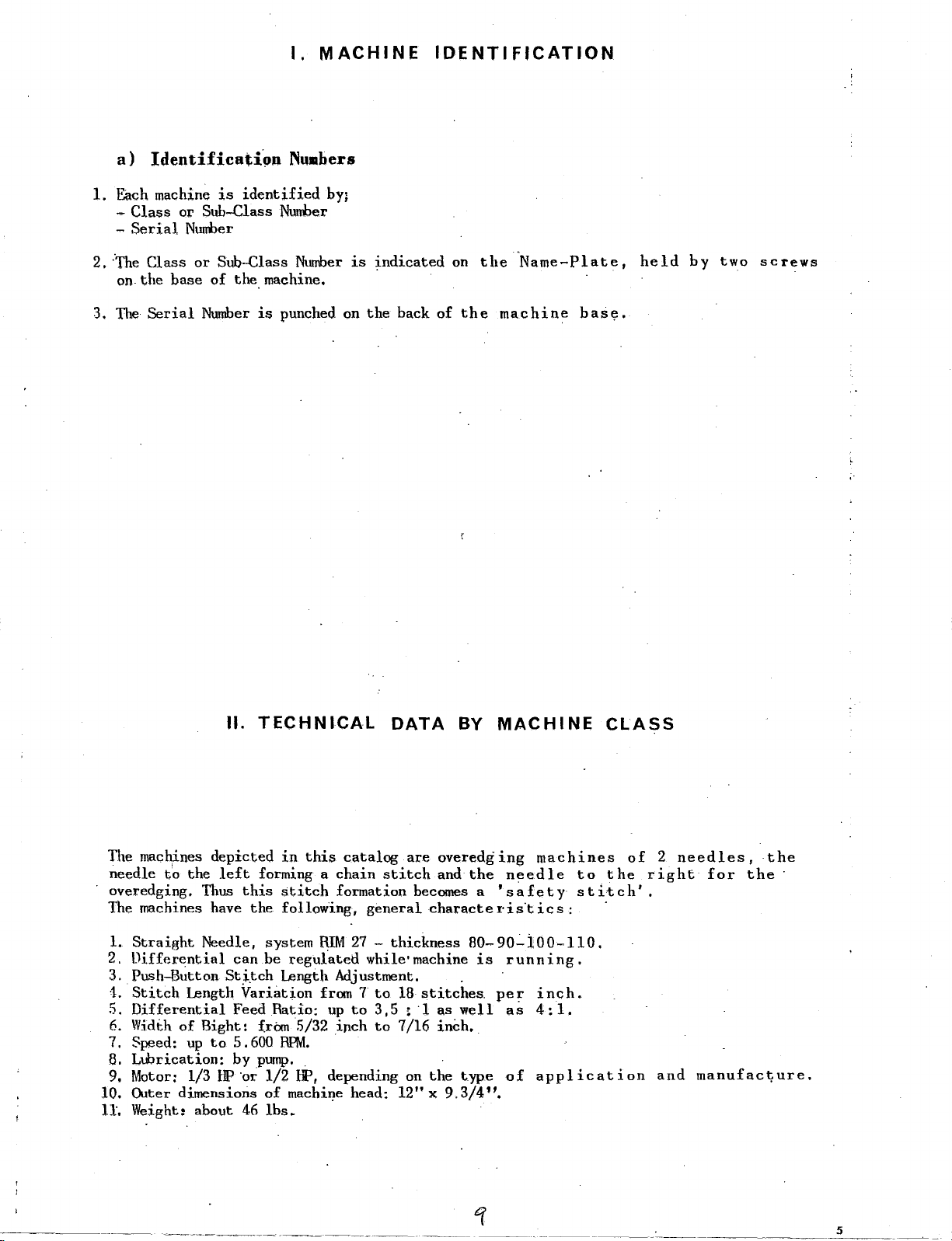
1.
Each machine
-
Class
-
Serial
2.
·the
Class
on.the
is
identified
or
Sttb....Class Nunher
Nunher
or
Sub-Class
base
of
the.machine.
I.
MACHINE
by;
Ntunber
1s
indicated
IDENTIFICATION
on
the
·Name-Plate,
held
by
two
screws
3. The
Serial
Ntunber
II.
is
punched
on
TECHNICAL
the
back
of
DATA
the
machine
BY
MACHINE
bas~.
CLASS
The
mac~ines
needle
overedging.
The machines have
1.
Straight
2.
Differential
3.
Push-Button
•1.
Stitch
5.
Differential
6.
Width
7. Speed;
8.
Lubrication:
9. Motor: 1/3
10.
Outer
11.
Weight:
depicted
to
the
left
Thus
Needle,
Length
of
Bight:
up
to
HP
dimensions
about
in
this
forming a
this
the
system
can
be
catalog
chain
stitch
formation
following,
RIM
regufated
27-
are
overedg
stitch
and
becomes a
general
charactei"is'tics:
thickness
while• machine
St.i.tch Length Adjustment. .
Variation
Feed
Ratio:
frbrn
5 .
600
by
pump
·or 1/2
of
46
lbs~
from 7
up
to
5/32
inch
RHvt.
.
..
HP,
depending on
machi~e
~~·---~-~-··
head:
to
18
stitches.
3, 5 ~ ·1
to
7/16
the
12" X 9.3/4".
-~-
as
inch.
ing
machines
the
needle
'safety
80-9o.:..too~UO.
is
running.
pe ~ inch.
well
as
4:
1.
t.ype
of
application
~-----
--~
to
the
stitch'.
·
-----~-
of 2 needles,
right
and
for
manufact;ure.
the
the
·
5
Page 6

Ill.
TECHNICAL
SPECIFICATIONS
TECHNICAL CHARACTERISTICS
Ill
MACHINE
SUBCLASS
~
Cl)
...
.
,;:;
...,
....
Q
z
0.29.0
,_
B.
·29
.1
B.29.1/B
0.29.1/PUU
B~29.1/PDUO
0.29.17
4
5
4
5
4
5
4
5
4
5
4
5
gauge
3/32''
2,5
3/64
mm.
1
3/64
1
111111.
3/64
mm.
1
3/64
mm.
1
13/64
11!11.
5
mm.
width
or
bight
5,5
4
4
4
4,5
10,5
N.
of
stitches
the
to
inch
7,5-18
7,5-18
7-,5-18
7,5-18
7,5-18
.
7-16
Ill
Cl)
>
ATTACHMENTS
....
J;:
,;,:
yes
yes
yes
Shirrihg
yes
Attachment
Shirring
yes
Attachment
yes
APPLICATIONS
Shil'ts!
Shirts;
Shirts,
general
Curtains,
cloth
Cloth
tion
in
of
general
ornaJtental
Trousers
SPECIFIC
c~oth
cloth
fine
bed-spreads,
in
general
in
general.,,
folded
cord
confection
-
in
in
cloth
tape
general
general
in
inser-
and
1J
..
29.17/PDB
B. 2 9.
1 7
/PD!.JO
8~29.174
B.29.7
U.29.7/R
1----·
8.29.7/W
8.·29. 7 /PDB
5
4
5
4
5
4
5
4
5
4
5
4
5
4
13/64
5
mm.
13/1!4
5
11111.
13/64
5
m111
3/32
2,5
•••
3/32
IIIII,
2, 5
3/32
2,
5
IIIII,
3/32
2, 5 ....
Shirr
10,5
11
10,5
•.
6
7
6
6
7
6
7
7-16
7-16
7-16
7,5-18
7,5-18
7,5-18
7,5-18
yes
yes
yes
yel5
yes
yes
yes
in~
Attachment
SMrr;l.ng
Attachment
Electric
cutter
ch11.in
Shirring
Attach11en t
Bed-spr~ads,curtains,
et.c·.
in
into
in
general,.
cord
confection
-
tape
sea!lls
general,
curtains
Cloth
t1on.of·folded
ornall!ental
TJ:ousers
general
in
shirts-cloth-confection
general
in
Reinforcing
tion
.Shirts-cloth-confection
general
in
Cloth
spread's.
tape
inser-
tnser-
bed-
ahd
m.i
...
•.
6,5
.7,11
6,5
7,5-18
7,5-18
l \
3)32
B.29.7/PDBQ
)}_. 2 9.
6
7 8
4
~
4
5
~.~~
3/32
:r,5
yes
yes
Shlrrlng
Attach11en t
of
sea•
in
in
Cloth
tion
or·na•ental
Cloth
ged
general,
fold-ed
general-overed.o
curled
cord
tape
downw·ard
inser-
and
Page 7

INSTALLATION
and
TIMING
-THREADING
- .MAINTENANCE
/
13
7
Page 8

Page 9
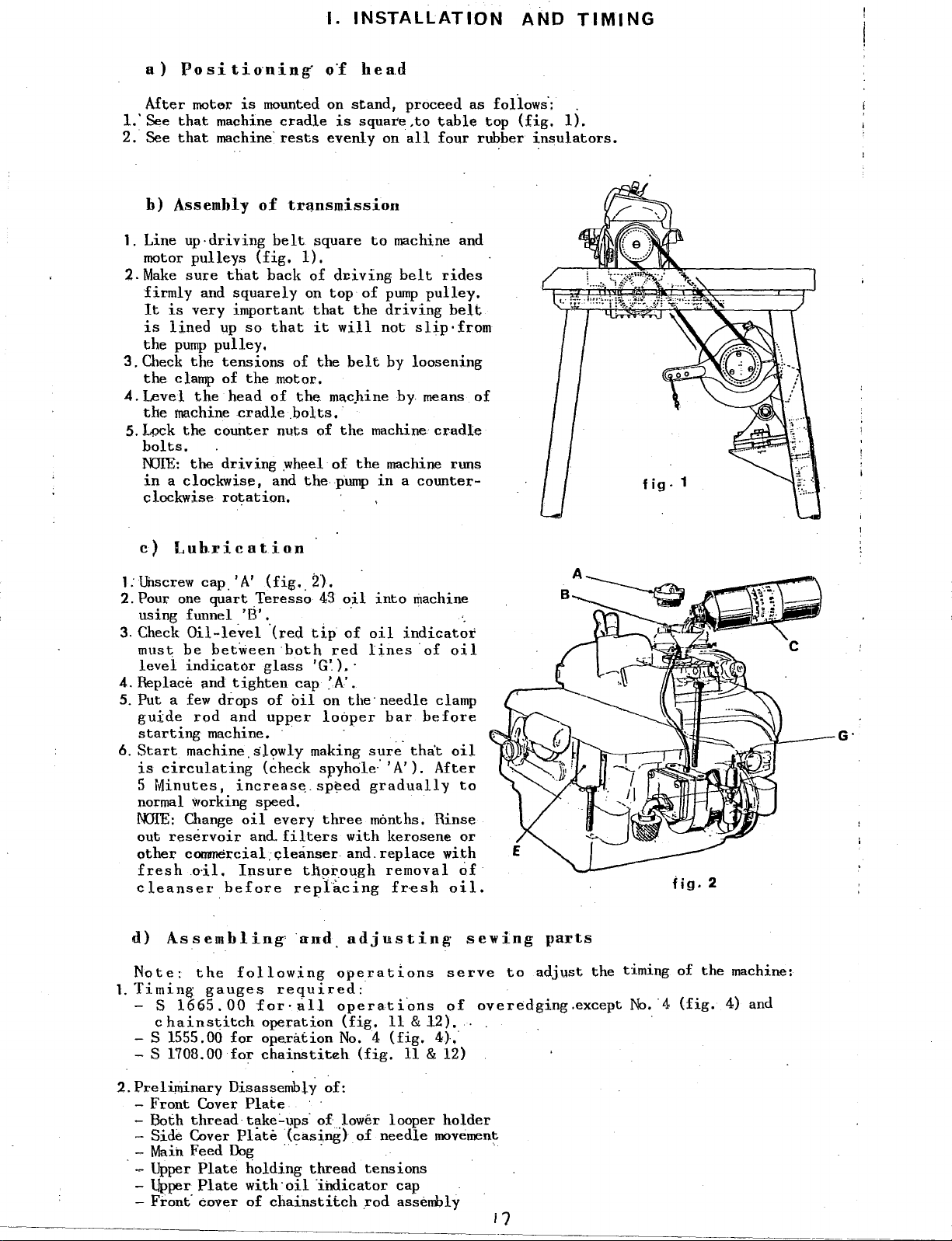
a)
After
1.'
See
2. See
b)
PositioninK
mot~r
that
that
is
machine
machine·
Assembly
I.
INSTALLATION
o~
head
mounted on
cradle
rests
of
tr~nsmission
stand,
is
sqnare,to
evenly
on
AND
proceed as follows·:
table
all
four rubber
top
{fig,
insulators.
TIMING
1).
1. Line
2.
3.
4.
5.Lock
motor
Make
firmly
It
is
is
lined
the
pump
Check
the
clamp
Level
the
machine
up-driving
pulleys
sure
that
and
squarely
very
important
up
so
pulley.
the
tensions
of
the
the
head
cradle.bolts.·
the
counter
bolts,
NJIE:
the
driving
in a clockwise,
clockwise
c)
L u b.r i
l:l.Ji:lscrew
2.Pour
using funnel
3. Check
must
levei
4.
Replace and
5.
Put a few
guide
starting
6.
Start
is
circulating
5
Minutes,
rotation.
cation
cap_
'A' (fig._
one
quart
_Teressa
'B',
Oil-level
be
bet~een
indicator
tighten
drops
rod
and
machine. · ·
machine.slowly
increas~.sp~ed
normal working speed.
l'DIE:
out
other
cleanser
fresh
Change
reservoir
oil
and.
commercial_c;leanser and.
~il.
Insure
before
belt
square
{fig.
1).
back
of
d1:iving
on
top
that
that
it
will
of
the
.motor.
of
the
mac.hine
nuts
of
the
.wheel
and
of
thepump
:n.
43
·(red
tip
both
glass
of
upper
(~heck
every
filters
red
'G~).
cap
'A'.
oil
on
looper
making
spyhole:
three
th~~ough
replicing
to
machine and
belt
of
pump
the
driving
not
belt
by loosening
by
machinecradle
the
machine runs
in a counter-
oil
into
machine
of
oil
indicator
lines
·
the.
needle
bar
sur~·
that
'A').
gradually
months. Rinse
with
kerosene
replace
removal
f~esh
rides
pulley,
slip·
means
of
clamp
before
After
with
belt
from
oil
oil
to
or
~~
oil.
of
fig.
1
fig.
2
d)
Assembling
Note:
1.
Timing
- S
- S 1555.00
- S
2.Preliminary
-
- Both
- Side Cover
-
. - Upper
-Upper
- Front· cover
the
1665.00
hainstitch
c
1708.00
Front
Cover
thread
Main
Feed
Plate
Plate
following
gauges
for
for
DisassembLy
Plate
tlllke:..ups·
Plate
Dog
holding
with·oil
of
and
adjusting
operations
required:
for·all
operation
ope.ration
chainstiteh
operati"ons
(fig,
11 & 12)
No. 4 (fig.
(fig.
11 & 12)
of:
of)ower
(casing)
of
looper
needle
· · · · ·
thread
·indicator
chainstitch
tensions
cap
rod
assembly
-------
sewing
serve
of
..
4}..
holder
movement
to
overedging.except
---------------~-~~-----~-
parts
adjust
the
timing
No.-4
of
(fig.
the
machine:
4) and
Page 10
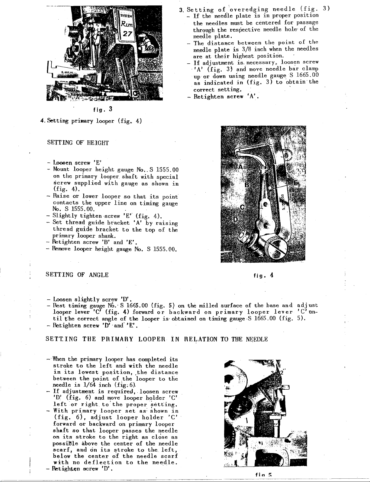
fig.
3
3.
Setting
-
If
the
through
needle plat.e.
- The
needle
are
- I£
·'A;
up
as
correct
-Retighten
of
.overedging
the
need"!e
needles
the
distance
plate
at
their
adjustment
(fig.
or
indicated
down
setting,
3) and
using
screw
plate
must be
respective
is
highest
is
centered
between
3/8
inch
is.
necessary,.
move
needle
in
(fig.
'A'.
needle
in
proper
needle
the
point
when
position.
needle
gauge S
3)
to
(fig,
position
for
passage
hole·
of
the
of
the
the
needles
·
loos':!n screw
bar
clamp
1?65.00
obtaw·the
3}
4.Setting
SETTING
- Looaen screw 'E'
-Mount
on
-
Raise
contacts
No.
-Slightly
-Set
thread
primary
-
Ret~ghten
-Remove
SETTING
pri~ary
OF'
looper
the
primary
screw
(fig.
supplied
4).
or
lower
the
s 1555.00. . .
tighten·screw
thread
guide
looper
screw
looper
OF
looper
HEIGHT
height
looper
with
looper
upper
guide
bracket
bracket
shank.
'B'
height
ANGLE
(fig.
gauge
shaft
gauge
line
to
and
gaqge
so
'E'.
'E'.
4)
No
•. S 1555.00
with
as
that
on
timing
(fig.
'A'
by
the
top
No.
S 1555.00,
special
shown
its
4).
raising
of
in
point
gauge
the
fig.
4
- Loosen
- Rest timing gauge
looper
til
-
Retighten
SETTING
-·When
stroke
in
between
needle
-If
'D:'
left
-
With
(fig,
forward
shaft
on
possi~le
scarf,
below
with
-
Retigh~en
r·--·-----·
slightly
lever
t"he
correct
screw
THE PRIMARY LOOPEI\
the
primary
to
the
its
lowest
the
is
1/64
adjustment
(fig.
6) and
or
right
primary
6,,
or
backward on
so
that
its
stroke
above
and
on
the
center
no
deflection
screw
screw
No.· S 16155.00
'C'
(fig.
angle
of
'0'
· and·
looper
left
and
po~ition,
point
adjust
of
inch
(fig;
is
required,.loosen
move
to.the
looper
looper
looper
to
the
the
center
its
~troke
of
'D'.
'D'.
(fig.
4)
forward
the
looper
'E:.'
.
has completed
with
the
.the
distance
.the
looper
6).
looper
proper
set
passes
right
the
to
holder
as: shown
holder
primary
the
as
of
the
to
needle
the
~~tting.
close
the.
needle.
5) on
or
backward
is·
its
needle
to
the
screw
'C'
'C'
looper
needle
needle
left,
scarf
· ·
the
obtained
IN
RE~ATION
in
·
as
milled
on
primary
on timing gauge·S 1665.00
surface
TO
THE
of
the
looper
NEf:DLE
fin
base
lever
;
and
(fig.
adjust
'C'
on-
5).
Page 11

5.Settin~
of
secondary
looper
fig_. 7
-
Special
the
c&re must
secondary
maintain a perfect
secondary
secondary
looper
looper
'C'.
-
Retighten
- Check
as
all
-.Retighten.
- Machine must
~he
screw
crossing
ot~er
settings.
screws 'A' and 'B'.
secondary looper. assembly.
turn
-Note: To
as
indicated
or
down
the
decreases.
·-
Slightly
-
Adjust.
looper,
that
ble
touchin
.,...
OJ.eck
- The •Secondary
left
close
If
screw
driving
or
proper
be
taken
looper
alignment
driving
pivot
sleeve
'D'.
of
both
loopers.
freely
setting
crossing
its
behind
obtain
considering
loosen
turning
poirit
the
distance
in
f:lg.
9,
move
lever
that
in
fig. 7 and B increases
in."
screw 'B' and 1 A'
of
secondary
the
l?econdary
-,passes·.as
th~-primary
and
Close
looper
• .
the
distance
to
rightt
as
possible
adjustment
'D'
and
assembly
backward
indicated
looper,,
must
without
l.s needed,
push
the
with
as
required
in
in
its
pass
the
touching.
loosen
comp,l~te
bushing
to
setting.
when
adjusting
assembly,
to
between
arm
'E'
and
in
bushing
as
well
. .
after
adjusting
of
11/32.,'
'E'
~oing
so;
primary
looper
as
possi-
witho~t
·fig.
7-8--9. ·
stroke
from
needle
slightly
looper
'C'
forward
obtain
the
up
or
·"""';"
'i'
so
I
':·;;,<:~·
·
as
fig·
6
fig
fig.
.10
9
- To
set
guard
it
slightly
. -
Set
the
- With
set
primary
to
right,
-'Tighten
-Set
while
-
Tighten
·-
Insert
position
needle
6.Setting
the
'D' on
needle
machine
the
needle
front
needle
looper,
barely
screw
needle
guard
needle
the
needle;
pushing
guard
the
needle
needle
with
guard
base.
'C'.
is
needle
bring
'Aj.
fig.
8
needle
guards
guards,
guard 'A; and
screw
'D'
'B',
with
·
in
its
lowest
guard
so
in
its
stroke
touches
'A'
in
close
its
guard
needle.
lowest
with
iri
it
slightly
mount
screw
that
to
to
(fig.
needle
tighten
'C'
position,
point
from
·the
needle
position,
screw
its
lowest
against
10)
on
of
left
'B'
.
- The
NOIE: The
Scarf
- For
and
thread
that
in
its
very
must
the
point
upper
hard
run
thread
of
the
portion,-
sythetic
freely.·
is
pressed
looper,·
fabrics,
and
If
this
between
in
in
its
its
the
is
not
needle
stroke
stroke
needle
the
to
must
case,
and
froot
the
touch
needle
left
left,
it
the
means
guard.
to
right,
in
needle
its
that
lower
the
must
guard
needle
enter
is
the
portion.
considerably.
too
low
needle
11
Page 12
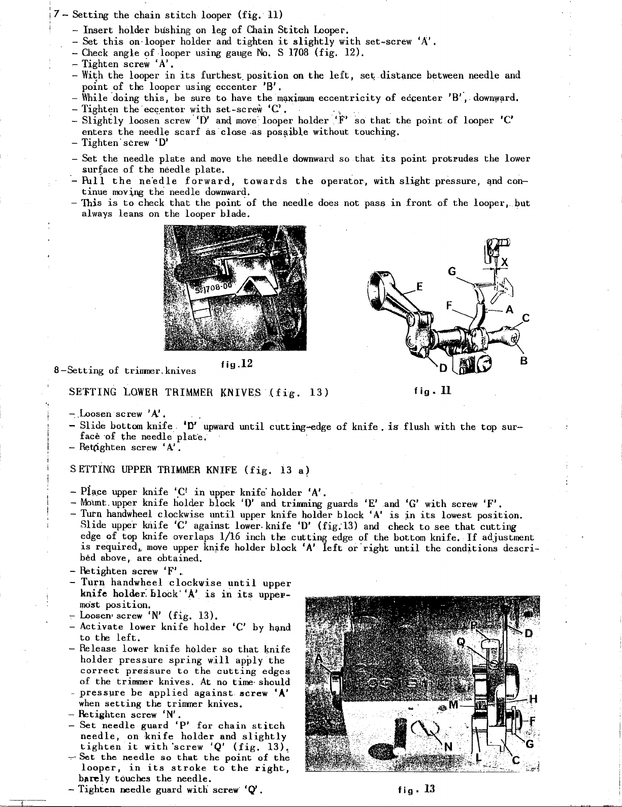
7-
Setting
-
Insert
-Set
-Check
the
this
angle
holder
on·
- Tighten screw I A'.
-
Wi~h
the
looper
point
-While
- Tightt;n
-Slightly
enters
-Tighten.
-
Set
sur;ace
·_Pull
tinue
-'This
always
of
·doing
the
the
the
moving
is
leans
the
the·
loosen
screw 'D'
needle
of
to
chain
stitch
bushing
looper
of
-looper using gauge
in
looper
this,
ec~_enter
screw
need!~
plate
the
needle
ne"edle
the
needle
check
on
that
the
on
holder
its
using
be
sure
~ith
'D'
scarf
and
plate,
forward,
the
looper
looper
furthest_
(fig,
leg
of
and
tighten
eccenter
to
have
set-screw
and
move.
as-close
move
the
downward.
point
blade.
11)
Chain
Stitch
it
No.
S
position
'B',
the
m~imum
•c,
looper
.as
pos~ible
needle
towards
·of
the
Looper.
slightly
1708
on
(fig.
the
with
12).
left,
eccentricity
..
holder
downward
the
needle does not
'F'
without touching.
so
.
operator,
set~screw
se~
dist~nce
of
eccenter
so
that
the
that
its
point
with
slight
pass
in
front
1
A',
between
point
protrudes
pressure,
of
'8'·,.
of
the
needle
downw!lrd,
looper
the
~nd
looper,.
and
'C'
lower
con-
but
fig
KNIVES
upper
block
until
lower.
l/16
holder
until
in
'C' by
so
will
cutting
no
time·
knives,
chain
and
'Q'
(fig.
point
to
the
screw·
.12
{fig.
until
cutting--edge
(fig,
knife'
'0'
upper
inch
its
that
apply
screw
slightly
1
(l
13
a)
holder
and trinming guards
knife
knife
block
the
holde.r
'D'
cutting
'A'
upper
uppeF-
h~nd
~nife
the
edges
should
'A'
stitch
13).
of
th~
right,
.
13)
'A'.
(fig;l3)
left
of
block
edge
or·
knife.
'E'
and check
of
right
8-Setting
SE'FTING
•,
-
..
-
-
SETTING
-
-
of
trinmer.knives
tOWER
Loosen screw 'A! , .
Slide
face ·of
~t(ighten
bottom knife_ 10'
the
screw 'A' ,
UPPER
Pi!i.Ce
Mo'unt.
upper
upper
needle plat·e,
knife
knife
- Tutn handwheel clockwise
Slide
edge
is
bed above,
-
Retighten
-
Turn
knife
mast
upper
of
top
required,,
screw
handwheel
holder:
position.
knife
knife
move
are
- Loosen• screw 'N'
-
Activate
to
the
lower
left,
- Release lower
holder
correct
of
-
pressure
when
-
Retighten
Set
needle,
tighten
~-Set
looper,
b~rely
-
Tighten
the
setting
needle
the
pressure
pressure
trimmer
be
screw
guard
on
·knife
it
with
needle
in
touches
needle
applied
the
its
TRIMMER
TRIMMER
'P
holder
'C'
overlaps
upper
obtained.
'F'
,
clockwise
bloek'
knife
(fig.
knife
spring
to
knives.
trinmer
'N'.
'P'
holder
'screw
so
that
stroke
the
needle.
guard
'A'.
holder
with
upward
KNIFE
in
against
kn~fe
is
13),
holder
the
At
against
far
the
'A'
the
is
flush
and 'G'
is
~n
bottom
until
fig
fig.ll
with
its
to
knife.
the
• 13
with
the
screw
lowest
see
that
If
conditions
top
sur-
'F',
position.
cutting
adjustment
descri-
Page 13
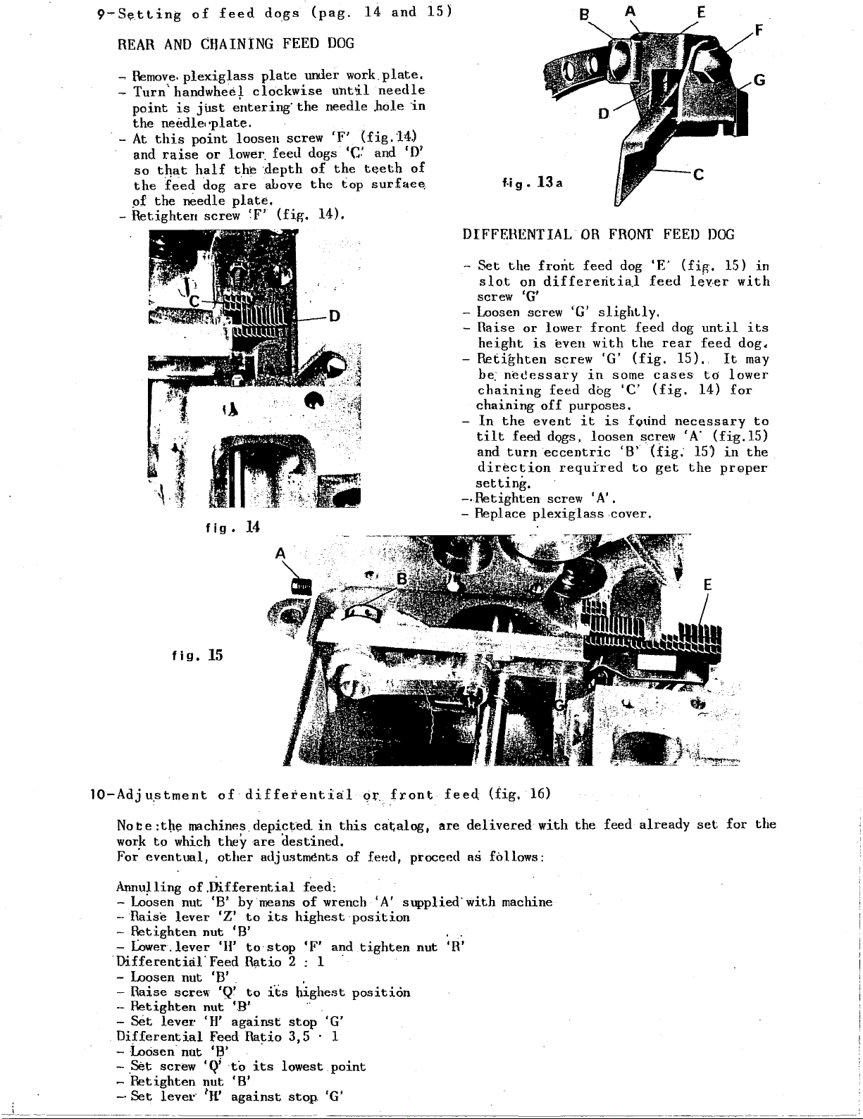
9-S~tting
REAR
of
AND
CHAINING
feed
dogs
FEED
(pag.
DOG
14
and
15)
B
A
E
F
-Remove.
-
Turn'
point
the
needle··plate.
· -
At
this
and
raise
so
t4at
the
f~ed
p£
the
-Retighten
plexiglass
handwhe.el
is
just
e"ntering·
point
needle
loosen
or
lower.
half
the
dog
are
plate.
screw 'F'
fig
•
plate
clockwise
the
screw
feeu
.depth
above
(fig.
14
under
needle
'F'
dogs
of
the
14).
work.
until
the
needle
hole
.
(fig
•c:
and 'D'
teeth
top
surfae~
plate.
in
.14.)
of
f.j
g.
13 a
DIFFERENTIAL
-Set
- Loosen screw
-
-Retighten
-
-·Retighten
- Replace
the
front
slot
on
differeritia.l
screw 'G'
'G'
Raise
height
h~
chaining
chaining
In
tilt
and
dir~ction
setting.
or
lower
is
even
screw
ne~essary
feed
off
purposes,
the
event
feed dogs, loosen screw 'A'
turn
eccentric
required
screw 'A' .
plexiglass
OR
FRONT
feed
slightly.
front
with
'G'
in
dog
it
is
dog
feed
the
(fig.
some
'C'
fotind
'B'
to
cover,
FEED
'E'
(fig.
feed
dog
rear
15).
cases
(fig.
necessary
(fig:
get
DOG
leyer
until
feed
td
14)
(fig.l5)
15)
the
G
15)
in
with
its
dog.
It
may
lower
for
to
in
the
pr0per
fig.
15
10-Adj
i
,-.-~------·-----·---------
u_stment
Not:
e
:th~
wor~
to
which
For
eventual I other
Annu~ling
- Loosen nut
-
Raise
-
Retighten
- Lower.lever 'H'
·rafferential'Feed
- Loosen nut 'B' . .
- Raise
-
Retighten
-
set
Differential
-
-i..oosen·
-_Set
-
Retighten
-·
Set
lever
screw
lever
screw
lever·
of
differential
machinP.s.
of.DQfferential
nut
nut '.B'
'H'
nut
'Q;
nut
1
H'
they
'B'
'Z'
'Q'
against
Feed
'B'
to
'B'
against
depicted.
are
adjustments
by
·means
to
its
'B'
tostop
R~tio
to
i'ts
Ratio
·
its
destined,
2 : 1
stop
3,5
lowest
st()p. 'G'
Qf.
front
in
this
cat;alog,
of
feed, proceed as follows:
feed:
of
wrench 'A' supplied·
highest
'F'
highest
··
position
and
position
tighten
'G'
· 1
point
nut
feed
are
'R'
(fig.
delivered
with
machine
16)
with
the
feed
already
set
for
the
Page 14
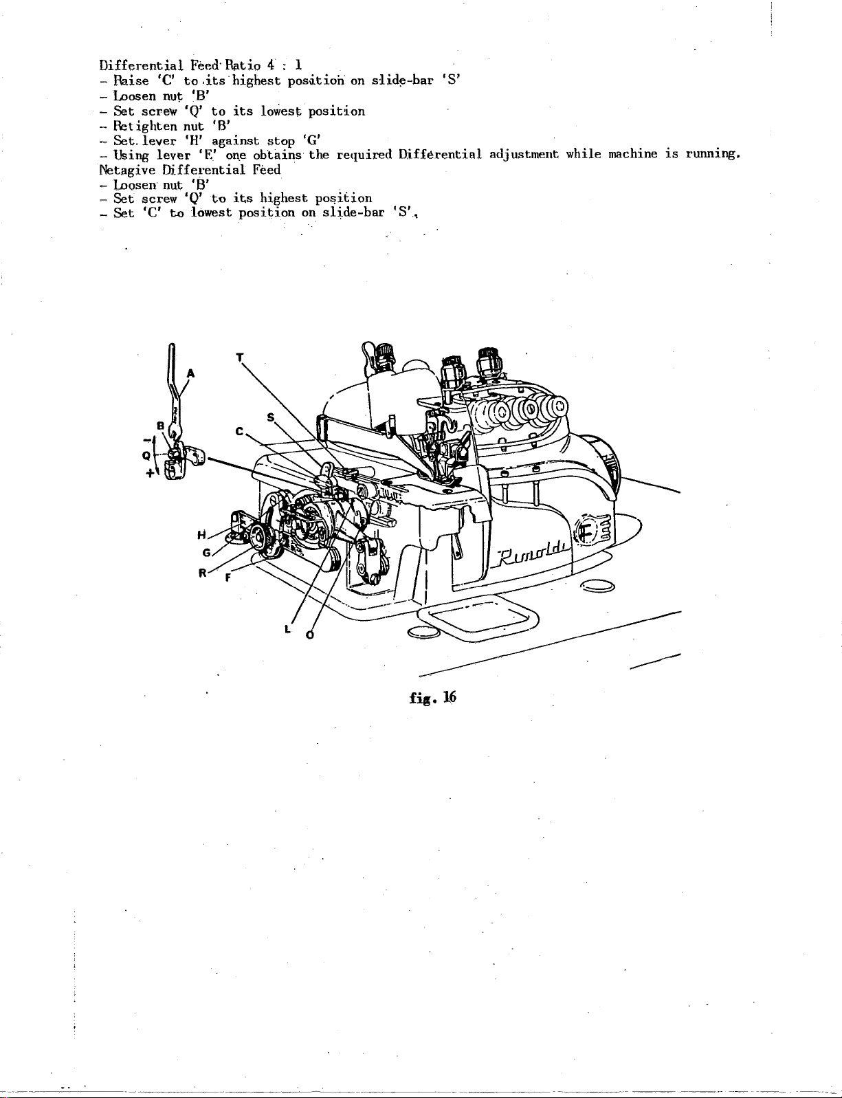
Differential
-Raise
-Loosen
-
Set
-&tighten
-Set.
- Using
Net.agive
lnosen·
-
-
Set
-
Set
'C'
nut
screw
lever
lever
Differential
nut
screw 'Q'
'C'
to
Feed·
to
.its
'B'
'Q'
to
nut
'H'
'E'
'B'
lowest
Ratio
highest
its
'B'
against
on.e
to
its
position
4 : l
posiitioh
lowest
stop
obtains
Feed ·
highest
on
slid!'l-har
position
'G'
the
required
po~1t1on
on
slide-bar
'S'
Differential
'S'.,
adjustment
while
machine
1s
running.
fi«.
16
Page 15
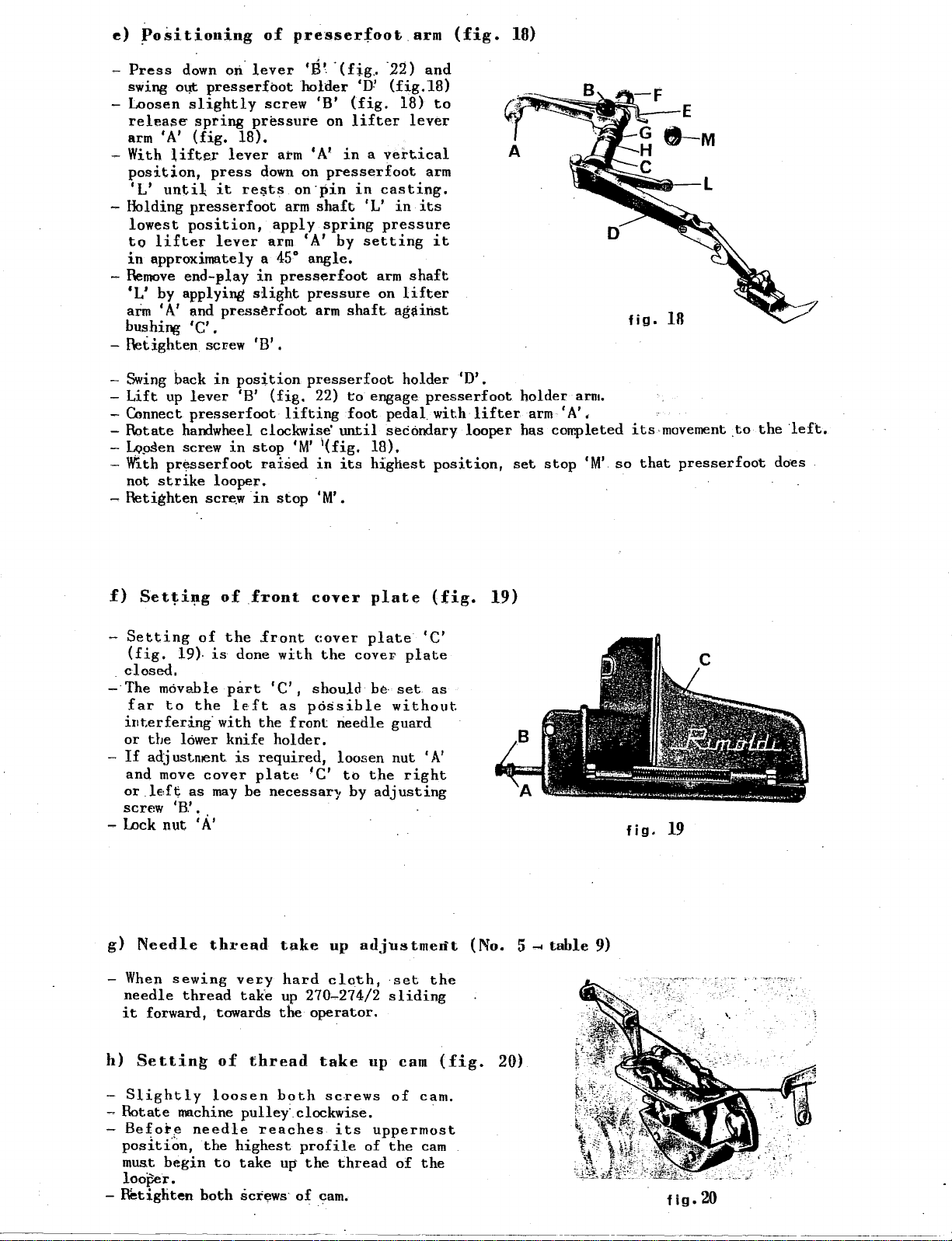
e)
~o~itioning
of
presserfoot
arm
(fig.
18)
-Press
swing
- Loosen
release
arm
- With
position,
'L'
- Holding
lowest
to
in
-
Remove
down
o~
slightly
spring
'A'
(fig.
lifte.r
untiL
presserfoot
position,
lifter
approximately a
end-~lay
'L' by applying
aim
'A'
and
bushing 'C' .
-
Retighten
-Swing
-
Lift
- Connect
-Rotate
-
Lo~en
- With
not
-
Retighten
back
up
lever
presserfoot
handwheel clockwise
screw
pr~sserfoot
strike
on.
lever
presserfoot
pressure
18).
lever
press
it
re~ts
lever
in
slight
press~rfoot
screw 'B' .
in
position
'B'
in
stop
looper.
scre.w
in
'B'.
holder
screw
down
arm 'A' by
(fig.
raised
'B'
on
arm
'A'
on
presserfoot
on·pin
arm
shaft
apply
spring
45°
angle.
presserf~ot
pressure
arm
presserfoot
22)
lifting
1
'M'
(fig.
in
stop
'M'.
'(fig
..
·22)
'D!
(fig.l8)
(fig.
lifter
in a vertical
shaft
to
foot
until
its
18)
lever
in
casting.
'L'
in
pressure
setting
arm
shaft
on
lifter
ag~inst
holder 'D'.
engage
pedal
secondary looper has completed its-movement
18),
highest
and
to
arm
its
it
presserfoot
with
lifter
position,
A
holder
arm
set
'A',
stop
arm.
'M'
so
fig.
that
18
.to
presserfoot
the
"left.
do~s
f)
Setti~g
-
Setting
(fig.
.
closed.
- The movable
far
interfering·
or
the
-
If
adjustment
and
or
.le:f~
screw 'B.'.
- Lock
g)
Needle
-
When
needle
it
forward, towards
19).
to
lower
move
as
nut
sewing
thread
of
the
cover
'A'
of
the
is
done
part
left
with
knife
is
may
be
thread
ve£y
take
front
front
with
'C',
as
the
front
holder.
required,
plate
necessaq.
take
hard
up
the
cover
cover
the
should
p6~sible
'C'
270-274/2
operator.
plate
plate
covet'
be·
set
without
needle guard
loor>en
to
up
cloth,
nut
the
by
adjusting
adjustmerit
set
sliding
(fig.
'C'
plate
as
'A'
right
the
19)
(No. 5
.....
table
9)
fig.
19
h)
Settin~
-
Slightly
-
Rotate
-
Be~ot~
position,
must
begin
looper.
-
Retighten
of
thread
loosen
machine pulley: clockwise. ·
needle
the
both
highest
to
reaches
take
screws
both
profile
up
of
take
screws
the
cam.
up
its
of
thread
cam
of
cam.
uppermost
the
cam
of
the
(fig.
20)
fig.
20
Page 16
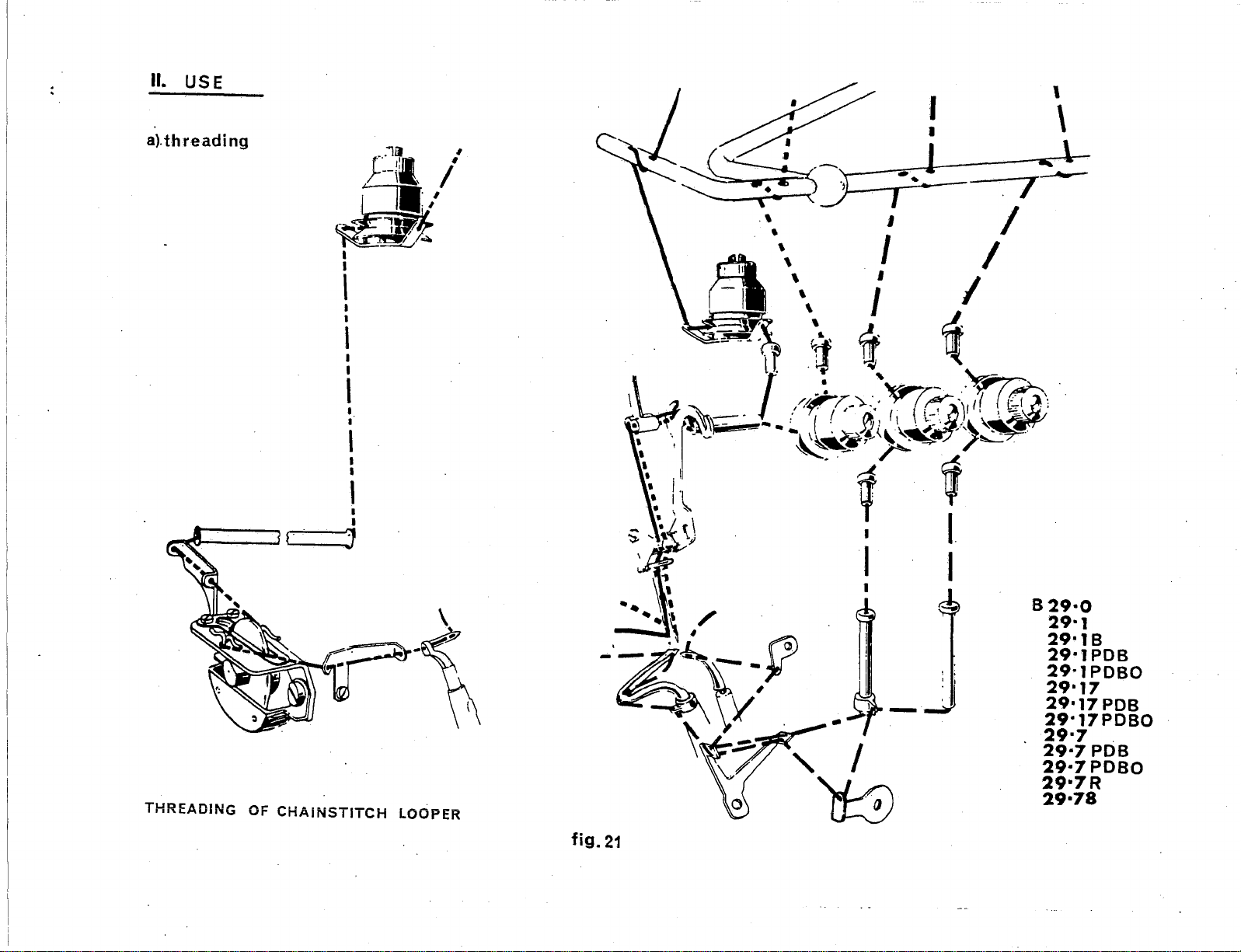
II. USE
a).
threading
...
1~
f--\1,
--
la:,
a
I
I
=-.,I
~
I
. I '
J~
/
~
~
~):
: I \
,.
.\
\ . I .
--~
.-1
7--
' I
f I
~~---.1
THREADING
! .
..,.... . .__.
OF
CHAINSTITCH
-:'
I
I
'
I
I
I
I
..
•
I
I
I
I
I
'
LOOPER
. I I
I '
l[
..
.'1
.
~~
~
·-.~~
-·~rv:?
~-
...
r~J~--~
II
I.
.
~
~
/~,-_,.~-
I
(
,~,~https://manualmachine.com/'''~«:.
~
•.
,(~\)
.
.,
/
-·
,~..,....?7',
~
tt
:J
'
~-
~·~
~~
\
c;.:~·),,(
-·
~~
, ·
~
..
y
I I .
_
_J
I
~
~
I
Yr'P.
~
-')·
'
~)
\.~r;Ji,
~'7"'·
,·
"~
! I;
829·0
29·1
29•18
29·1PDB
29·1
PDBO
29•17
29•17
29•17PDBO
29·7
29·7
29•7PDBO
29•7R
29·78
PDB
PDB
~
fig.
21
Page 17
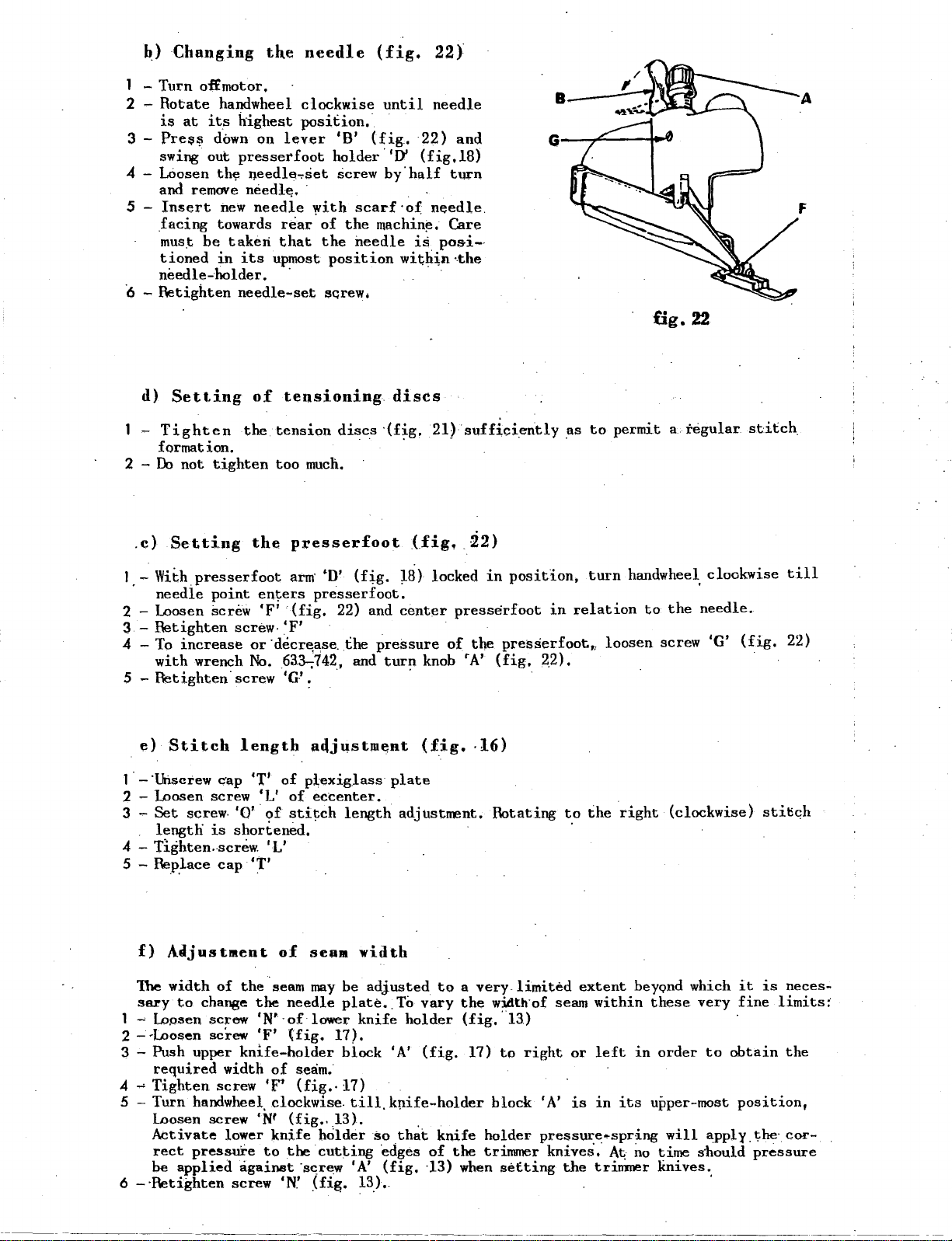
~)
Changing
1 -
Turn
of£
2 -
Rotate
is
at
its
3 -
Pres~
swing
down
out
4 - LOosen
and
remove
5
Insert
,facing
mus.t
be
tioned
needle-holder.
·6 -Retighten
d)
Setting
-
Tighten
formation.
2 -
Do
not
tighten
the
motor,
handwheel
highest
presserfoot
th~
needle~set
needl~.
new
needle
towards
taken
in
its
needle-set
of
the
clockwise
position.·
on
lever
rear.of
that
upmost
.
tensioning
tension
too
needle
'B'
holder
screw
with
the
the
position
SGrew;
discs
much,
(fig.
until
(fig.
.,D'
by'half
scarf
machi~~.
needle
22)
needle
22)
and
(fig,l8)
turn
·of
needle.
Care
is
pos-i-·
wit;h:i,n ·.the
dises
·(fig.
· · ·
21)
sufficiently
B
G-~"----t-
fig.
as
to
permit a regular
22
stitch.
.c)
Setting
1.-
With
needle
2 -
Loosen
3-
Retighten
4 - To
5 -
1 ·
2
3 -
4 -
5 - Rep.J.ace
2
3-
4 4
5
6
increase
with
Retighten·
e)
Stitch
-'Unscrew
-Loosen
Set
screw.
lengtli
Tighten
f)
A~justment
1he
width
sftl'y
to
~
l.opsen
--Loosen
Push
upper
required
Tighten
-Turn
-·Retighten
handwheel
Loosen
Activate
rect
pressure
be
applied
the
presserfoot
point
screw
wrench
screw
is
chanse
screw
screw
screw
en~ers
'F'
screw-'F'
or
No.
screw
length
c·ap
'T1 of
'L'
'0'
·of
shortened
..
screw.
cap
'T'
of
the.seam
the
'N'·of
'F'
knife-bolder
width
screw
'Nf
lower
agaiMt
screw
p~esserfoot
arm·
•n•
(fig.
presserfoot.
·(fig.
"decr~ase.
63.3-;742, and
'G'.
22)
the
. ·
a!ljustiUent
plexig.lass
of
eccenter.
stitch
'L'
of
needle
(fig.
of
seam.
'F'
(fig.·
clockwise.
(fig,.l3).
knife
to
the
'N.'
..
seam
may
lower
17).
holder
cutting
·screw
_(fig.
length
width
be
plate
knife
block
17)
till
'A'
13).
(Jig,
W)
and
center
pressure
turn
(fig.
plate
adjustnent.
adjusted
..
To
vary
holder
'A'
knife-holder
. . .
so
that
'ed.ges
(fig.
knob
(fig.
~2)
locked
in
presserfoot
of
the
presserfoot,,
'N
(fig,
position,
·16)
Rotating
to a very.limited
the
w:idth·of seam
(fig
•.
l3)
17)
to
right
block
knife
of
·13) when
the
holder
trimner
setting
turn
handwheel.
in
relation
loosen
to
the
screw
needle.
2_2).
to
the
right
extent
within
or
left
'A'
is
1n
its
pressure~spring
knives."
A~
the
triDIJ~er
(clockwise)
beyond
these
in
order
upper-most
will
no
time
knives.
which
very
to
apply.the·
s·hould
clockwise
'G'
(fig.
stitic:h
it
is
fine
obtain
position,
pressure
·
till
22)
neces~
limits:
the
cor-
~~-·-~-
~------~·---~-~~--···--.
Page 18
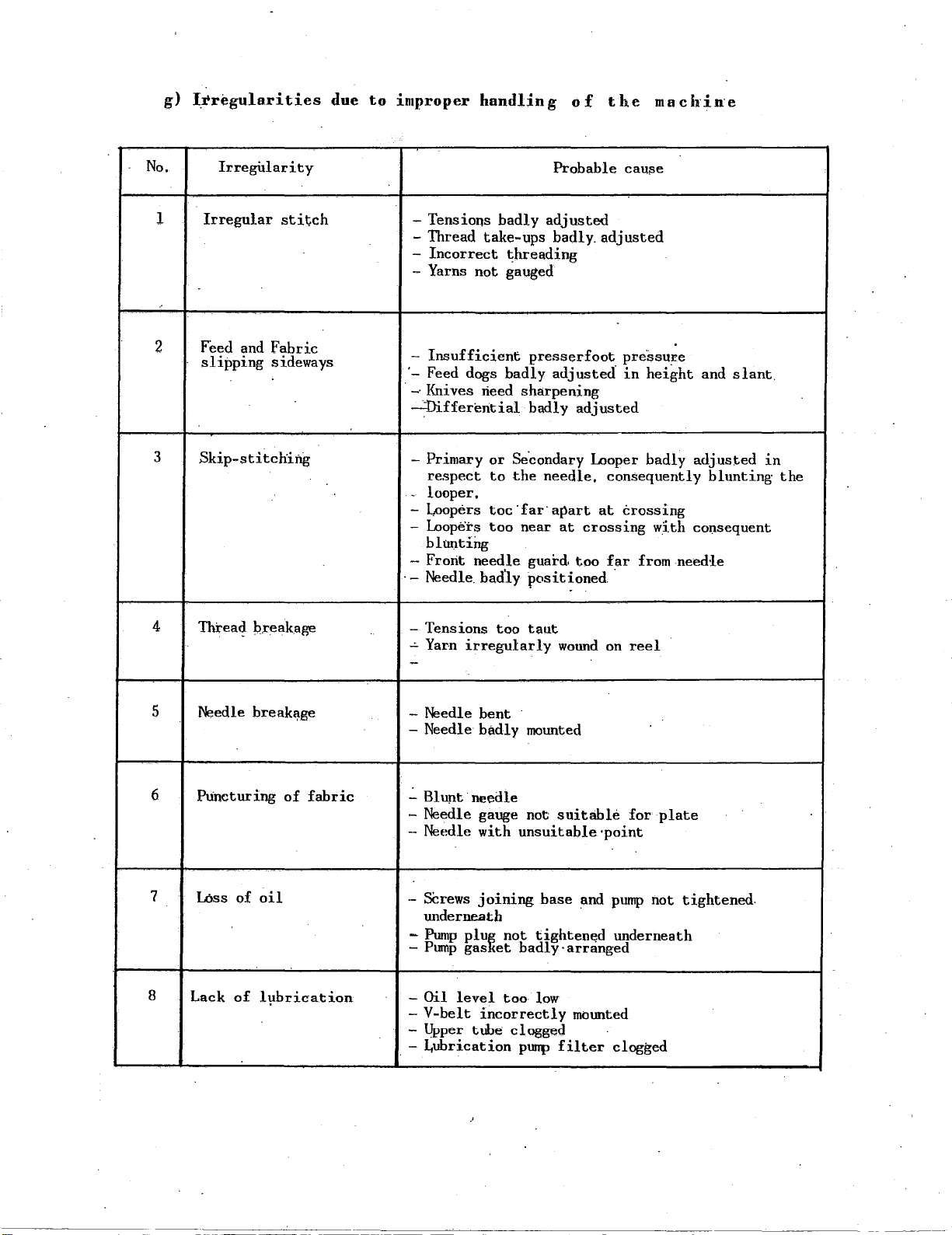
g)
I.rregularities
due
to
improper
handling
of
the
macb·in·e
No.
1
..
2
3
Irregitlarity
Irregular
stitch
Feed and Fabric
slipping
sideways
Skip-stitching
- Tensions
-Thread
-
Incorrect
badly
take-ups badly.
~breading
- Yarns not gauged
Insufficient
-
·-
Feed dogs badly
-Knives
~fferential
need sharpening
- Primary
respect
looper,
-
Loopers
-
-
Loope·rs
presserfoot
badly
or
Se.condary Looper badly adjusl:.ed
to
the
toc·far·apart
too
near
blUI:ttiilg
- Front
·-
Needle. bad'ly
needle guard
posit~oned
Probable
cau~e
adjusted
adjusted
pre.ssure
adjusted
in
height
adjusted
needle, consequently
at
crossing
at
crossing
too
far
with
from
co1;1sequent
needle
.
and
slant.
blunting
in
the
4
5
6
7
Threa?
Needle
Ptincturing
L6ss
Q.reakage
break~ge
of
fabric
of
oil
- Tensions too
-'-
Yarn
irregularly
-
- Needle
-Needle
.:_
.
bent
badly
Blunt needle
taut
mounted
- Needle gauge not
-Needle
-
SCrews
with
unsuitable·point
joining
wound
suitable
base
and
on
reel
for
pump
not tightened.
plate
underneath
Pump
plu~
not
-
-Pump
8
Lack
of
l1;1brication
-Oil
-
-
. -
gas
level
V-belt
Upper
incorrectly
tube clogged
Lubrication
tighten~d
et
badly-arranged
too
low
purrp
filter
underneath
mounted
clogged
----------~----~------------------------------~----------
--------~
Page 19

a)
Every
Ooy
Ill.
MAINTENANCE
.
1.
2,
3,
1.
2
•.
Clean
b )
Clean
looper
(\len
Clean
c)
Wash
Wash
the
Every
thoroughly
•
front
the
Every
tne
oil
tfle
pump
Week
Dtrec
3. Blow· purrp and
4.
Fill
with
fresh
d) Sharpening-the
Sharpen
block
request.
the
that
e) IJ.lst;.ruct·ions
feed
and
dismounting
c6ver
plate
inside
M-:mths
basin
with
filters
filter
oil.
knives
guarantees
using
for
stitch
and
of
the
kerosene
with
with
Knives
the
the
.removing_
formation
feed
carefully
cover
kerosent::
compres~ed
'Rimold1'
exact
plate
or
angle
i_he
elements
dogs,
clean
other
au.
cam
rear
containing
Knife
of
shaft
briefly.
and
front
the
fr-ont
commercial
Sharpener
sharpening.
needle
opening,
t-he
needle
cleanser.
and
This
guards,
movement
using
block
and
the
appropriate
is
supplied
primary
assembly.
on
-
Too~s
-
Pincers
-
Pincers
-
ExtractQr
It
re-assenhled
-
-
-
- The
-
-Carefully
necessary
is
absolutely
Reassamble
beave
·all
Cor.necting
e~graved
2
the
surface
position:ir'g
cap
and
th~
_par.t;
The
assembly·
must
he
supplied
type
S
0590/00
type
S
0459/00
S
0416/00,
necessary
kecpjng
flanges
locking
rods
on
the·
of
ccrmecting
on
the
hocly
pusit·ion
on
the
part-of
obser~e
on
request
·
IMPORTANT
that·,the
theh·initial·posjtion.
'G'
and
screws
'J'
surface
of
the
and
the
cC-nnecting
of
the
._of
the·
o.t'der
of.the
'L'
of
the
rod
comt(':c;ting'
connecting
handwheel,
of
only.
-rpain
-elements
'T'
in
the
connecting-rod
are
distinguished
head
of
'.J'.
rod
cep
rod.
rod
assembly·
of
of
Therefore
lubrication
cap
from
connecting'·
is
detern:ined
The two
'N'
is
give~
the
Cl.lf!
the
shaft-connecting
proceed
hole,
1n
their
oneanother
rod
'L'
by a cut
cuts
are
by
the
springs.
as
follows:
towards
own
hol~s.
and,
made-
on
t-he same
drawing
by
three
red,
the
.
tlie
lines
both
number
ar.e
bottom.
number
on
on
the
side
of
that
--------------
-------
----------
Page 20
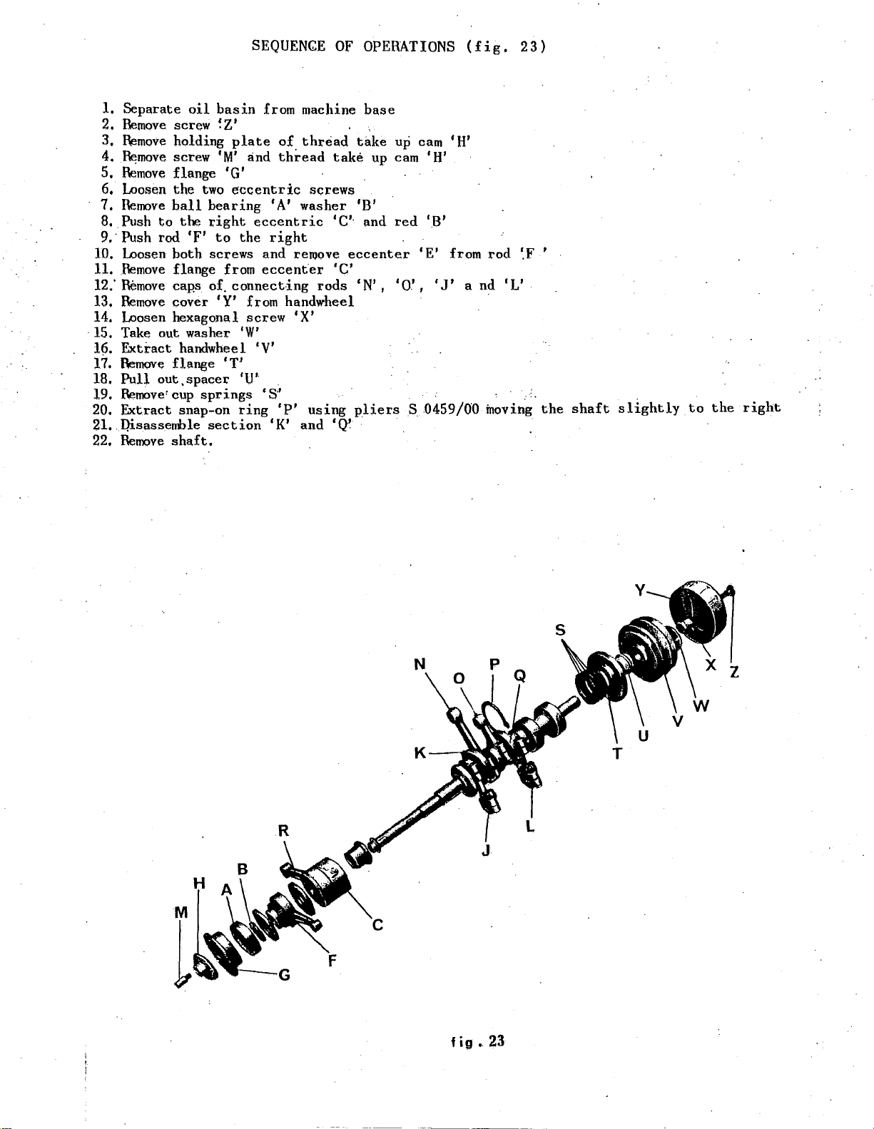
1.
Separate
2.
Bemove
3,
R¢move
4.
~move
5.
Remove
6, Loosen
7.
Remove
8,
Push
9.-Push
10, Loosen
11.
Remove
12.'
Remove
13.
Remove
14.
Loosen hexagonal
·
15.
Take
16.
Extract
17.
Remove
18.
Pull
19.
Remove'
20.
Extract
21..l}:i.sassemble
22.
Remove
screw
holding
screw
flange
the
ball
to
the
rod
both
flange
cap,s of.
cover
out
handwheel 'V'
flange
out
,spacer
cup
snap-on
shaft.
oil
SEQUENGE
basin
~Z'
'M'
from machine
plate
and
of
thread
OF
thread
take
OPERATIONS
base
take
up cam 'H'
up cam 'H'
'G'
two
bearing
right
'F'
screws
eccentric
eccentric
to
the
and
from
eccenter
connecting
1
A'
right
reroove
screws
washer
'C'·
'C'
rods
'B'
and
red
eccenter
1
N'
, 1 0'
'E'
,
'Y' from handwheel ·
washer
springs
section
'T
screw
'W'
1
'U'
ring
'S''
'K'
'P'
'X'
and
using
'Q'
pliers S 0459/00
'B'
1
from
J'
(fig.
a
nd
23)
rod
~F
1
L'
inoving
'
the
shaft
slightly
to
the
right
M
l
fig
•
23
Page 21
' -
. .
SPARE
PARTS
-CATALOG
- l -
. \
. i
'
'
!
i.
I
i
!
i
'
i
'
(
. !
..,,
;
!
I
I
.
Page 22

Page 23

a)
1 ·
The
parts
all
2 ·
In
order
of
each
3-Ttie
single
4
·The
. a number,
·by
capital
not
seaming
5
-The
numbers
these
1 -
If
the
numerical
·
If
2
the
is
known,
renee,
Introduction
spare
derived
conversion
var-ious
normally
catalogue·
parts
and
groups
from
to
make
group
tables,
TI1e
letters.
operations.
of
all
pacts
are
number
in'dex,
·ntllllher
the
inside
groups
group
groups,.
supp.lied
is
component
of
of a part
illustrated
HOW
catalog
which
Basic
the
comp:leted
illust~ated,
the
make up
Class
use
of
the
machine. ·
of
of
components
whose
TI1.e·
parts
with
part
is·
TO
is
made up
the
29,
this
catalog
the·
basic
illustrated
parts
the
with a general
parts
1s
.not. known .
index
canriot
cross-referenced
machine,
of
the
known,
of
USE
tables
THIS
of a series
basic
easier.
machine
be
but
machine
its·
drawiiJg
."
but
machine
numeric.a~
·
its
w~ll
CATALOG
of
and
the·
and
its.
on
each
supplied
by a nunher
can
be
and
listing
may
approximate
give
tables
index
sub~lasses,
separately,
supplied
index
be
the
its
table,
found
position
relative
illustrating
subclasses,
of
tables
are
are
cross-referenced
are
w·ith
an
upon
request
.
g1V1ng
the
at
the
page
once
page
asterisk
or
within
the
various
the·
latter
shows
the
position
illustrated
cross--referenqed
(*)
for·
special
cross-reference
pages
by
for
in
consulting
the
machine
easr.
which
refe-.
are
1n
by
are
the
a)
All
1-To
insure
have
2-Give
3·Give
4-
5-Indicate
'the
List
The
Rimoldi
gularity
along
b) Needles
1·
Only
catalog.
2-
The
needle
3-
The
gauge
calculated
4 -The
5-It
the
system
is
needle
parts
immediate
to
be
stricly
serial
th~
referenc~
the
full
,and corr(>lete
qu~ntity
Company
found
with
the
only
straight
system
inP,icates'
on
the
and
advisable,
required
HOW
shipment
ooserved·~
number
on
order
RIM
the
when
of
number
desir~d.
wish~s
parts
27
and
blade
gauge
for
needles
gauge
the
placing
(ex.:
produced
spare
average
of
are
TO ORDER SPARE
of
the
required
the
machine,
of
the·
name
re~1ired
of.
the
part,
part"
I M P 0 R T A N T
tobe
the'rteedle.
100
parts,
may
are
marked
alscr
ordersr
needles,
able
to
by
them
be
·used
on
diameter
stamped
to
gauge
analyse
•.
the
on
always
PARTS
spare
parts,
itse~f.
any
case
For
th_is
reason
on
the
·machines
shank
expressed·
the
-90,
of
envel!:!pes
state
clearly
system
in
the
of
the
needle.
hundredths
of
RIM
27).
.following·
breakage,
please
illus"trated
Rimoldi
the
remit
of a millimetre
system
instructions
wear
these
within
needle,
and
or
irre-
gauge
parts
this
of
Page 24

-------
----
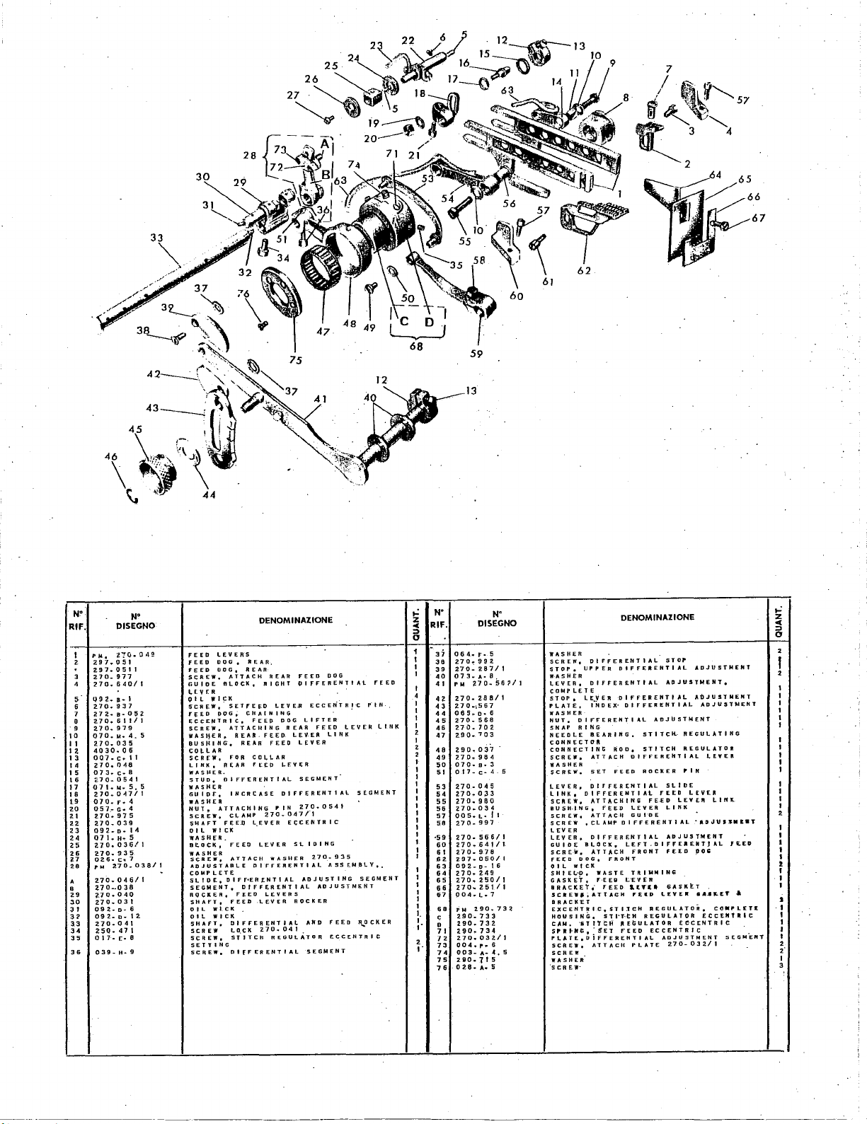
Page 25
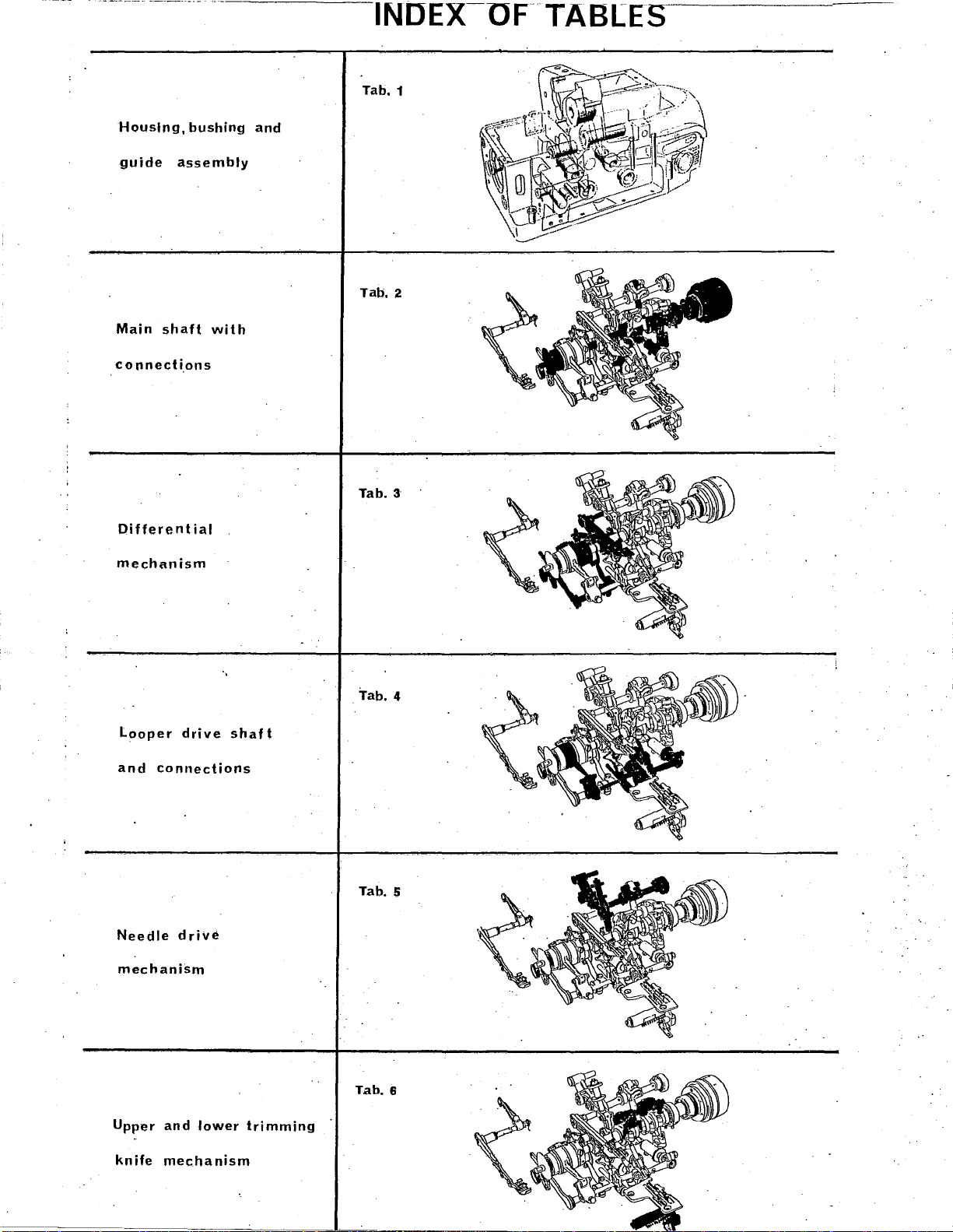
INDEX-OF
Tab. 1
nTABLES
Housing,
guide
Main
connections
Differential
mechanism
assembly
shaft
bushing
with
and
Tab.
Tab. 3
2
Looper
and
connections
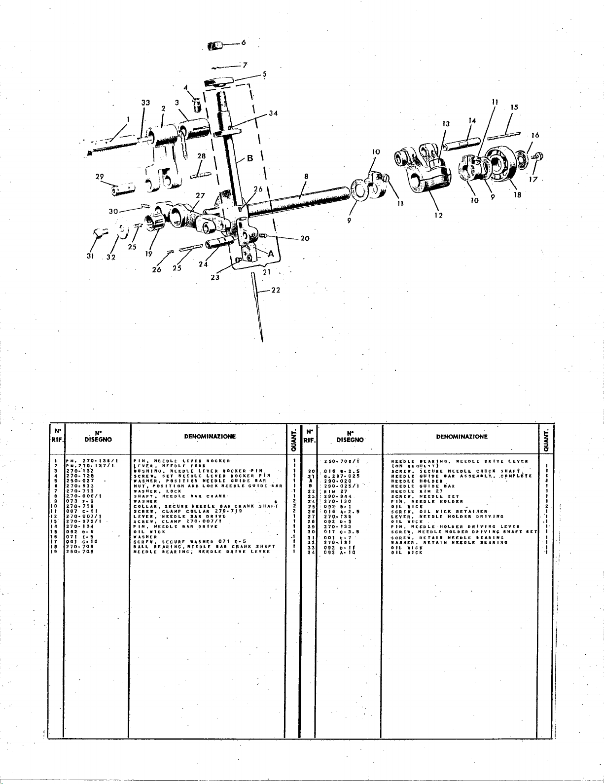
Needle
mechanism
Upper
drive
and
drive
lower
shaft
trimming
Tab. 4
Tab. 5
Tab.
6
knife
mechanism
--------'----
Page 26

Tab. 7
Presserfoot
and
needle
Machine
work
Thread
and
plate
tensions
plate
cover
take-up
linkage
and
Tab.
Tab. 9
8
Oil-pump
oil
basin
Machine
and
knee
Thread
foot
pedal
and
mounting
contro·l
stands
and
brackef
Tab. 10
Tab.
11
Tab. 12
-rr-
··~-
~4
..
~JL_
.
.
Tab,
13
Accessories
Page 27
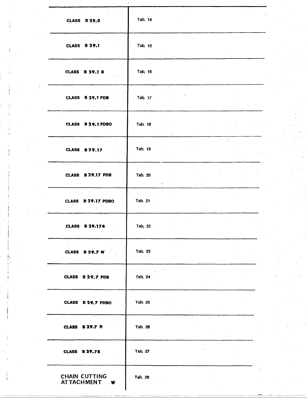
CLASS
CLASS
B
B
29.0
29.1
Tab.
Tab.
14
15
CLASS B
CLASS · B
CLASS B
CLASS
CLASS
CLASS B
29,1
29.1
29.1
829.17
B
29.17
29.17
B
PDB
PDBO
PDB
PDBO
Tab. 16
Tab. 17
Tab. 18
Tab. 19
Tab. 20
Tab.
21
CLASS
CLASS
i
I •
CLASS
CLASS
CLASS
CLASS B
B
29.174
B
29.7
B
29,7
B
29.7
829.7
29.71
W
PDB
PDBO
·
R Tab.
Tab,
Tab.
Tab.
Tab:
Tab.
23
24
25
26
27
22
..
CHAIN CUTTING
ATTACHMENT
w
Tab. 28
Page 28

Page 29
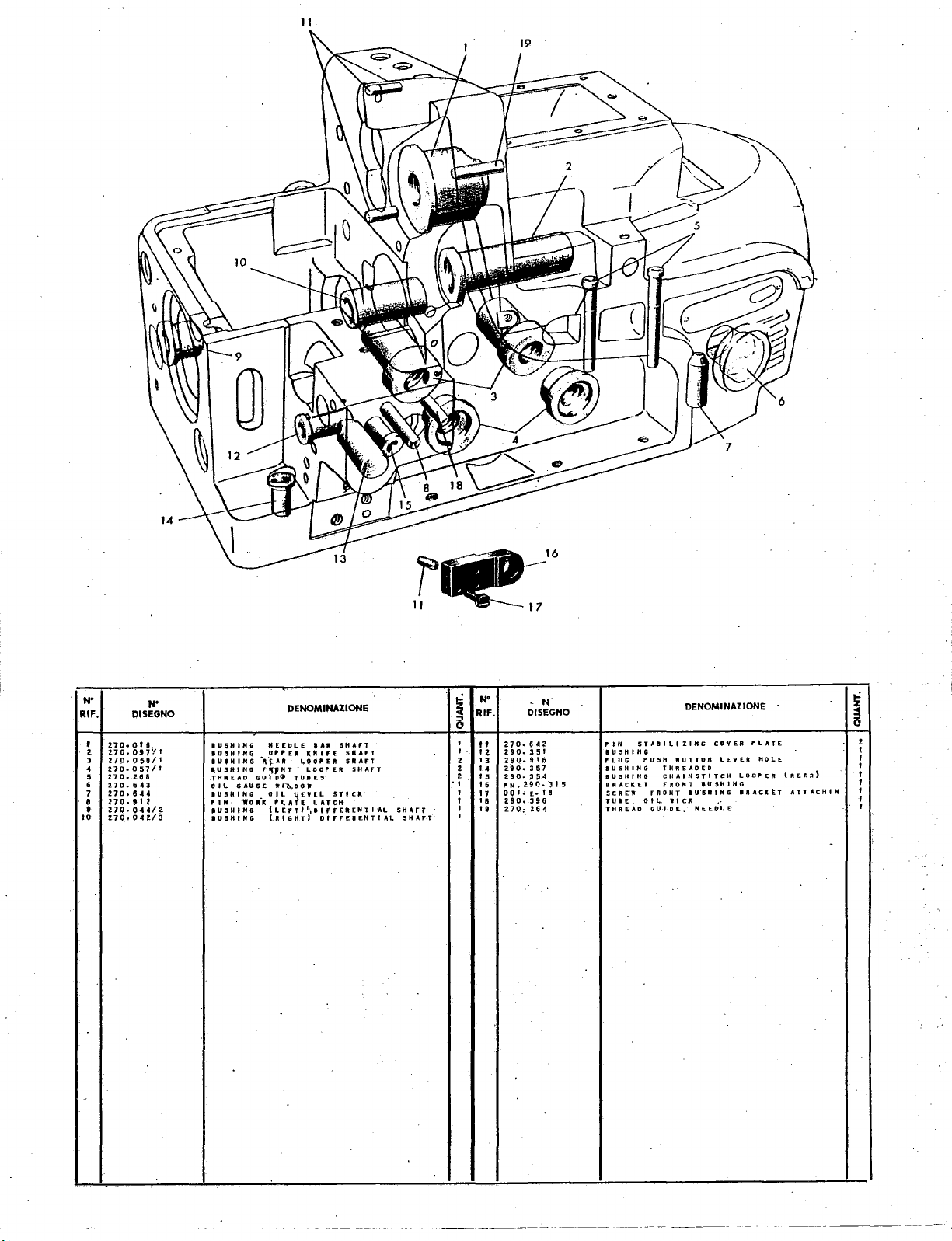
11
N"
RIF.
t
2.
3
4
5
6
7
e
10
'
DISEGNO
Z7o.ote,
270.
097'/
27().051!1/1
2.70
..
057/1
270.2Ei8
• 7
o.
6.
Z7o.e
Ho.
''
Z70·0HIZ
270
..
042/3
3
H
z
...
I
lUSH
IUSHIHG
IU$HIHG
.USHI
.THREAD
0
ll
JOSHING
...
•
U5HIHG
•usHING
lNG
"EEOLE
UPPEA
..
lt.{-•'~'
HG
r·'JJINT'
GU1o~
G
AUG£
W
OJ~
woaK
Pl.ATl
(LEfT)1,DifFEIIENTI
(.RIGHT)
DENOMINAZIONE
SHAfT
•••
SHAfT
KNIFE
·
~UJ£5
fl&,D
"'tEVEL
.l.OOP.£11
LOOPER
0 J
LATCH
DIFFERENTIAL
SHAFT
STtCK
SHAFT
r
11
...:
N'
z
-c
RIF.
5
It
'
'z
'
13
z
z
'.
z
'5
.,
16
17
I
'
AL
SHAF'J
5
HAFT'
••
'9
'
'
'
DISEGNO
270-6H
290.351
290·9'.6
z·go.
3
~7
Z90·J54
PN.Z90-315
00
1.;
E•
090--396
270~
26
N .
PI
lUSH
PLUG
lUSH
BUSHING
t 8 5 C R
4
BRACKET
TUIE.
THREAD
DENOMINAZIONE
~
8
ZING
lUTTON
WI
CJt
.
JOSHING
IU'SHING
NEEDL~
COVER
lEY
ER
HOLE
LOOPER
IJtACKtT
(It
E
ATTACH
~R)
STAll
E'W
lNG
lNG
PUSH
0
ILl
THREADED
CHAIHSTITCH
fRONT
FRONT
ll
GUIDE
H
rLATE
z
I
I
I
I
I
IN
'
I
I
-
Page 30

·--
~1-·-.
_,
, I
N"
RIF. !liSEGNO
I
t
AI
lei
•
(c)
I o I
(E)
(G)
2
3
4
5
6
7
B·
9
10
11
I 2
N"
~10-
PW
i7D~012./2.
2.70rft6/2:
270-0$1/2
ZJ0.060/1
H0-05~/1
2.10·
7Q7
270·
70
4
HO•
70
5
~70
..
620
270.
61
.4
27.0
..
001/1
270.612
270-981
270~
608
270,
61
0
270-617/1
270
..
999
009/~
MAIN
SHAFT
,
CONNECTING
CONNECTING
CONNECT J NG
UPPER
CR
AN~
CR
AN
1\:,
I. 0 WE R
II
ALL
IEARfNG,,
SNAP
RING
JP R IN
0
WASH
FI,.ANGE,
SPACER,
p
IJ
ll
y •
DRIVING
WASH
£It,
$HAFT
SCREW,
ATTACHING
COY
Ell,
PULLY
STUO
_8ALAJ.ICERS,
SCREW
"ATTACHING
DENOMINAZIONE
CQMP
R
DO,
.ROD,
R D
D,
LOOPER
LOOPER
RIGHT
E;
It
RIGHT
HANDWHEEL
POSITIONING
MAIN
I.,.ETE.
flEE~(,.[
UP P Eft
UPPER
,
UlLY
PULLY
5 HAFT
IALANCERS
&
kN
•••
If
LOWE
OVER
TO
t
SHAFT
A
I. 0 CH E R
MAIN
,_:
z
RIF.
:::>
""
0
I
I
I
2 1 6
I
1
2
1
4
1
1
I
I
1
1
1
2
4
N"
OIOH
1 3
2.70
14
004
15
092p
270-615
1 7
1 B
270.010/1
074A.I2
19
290.308
zo
073N
21
ao.
22
270.938
23
24 0 17
25
00
01Do-11.5
26
2704613
H
270-709
L
270.062
29
30
017.c-3
DISEGNO
..
..
975
..
£7
..
•.
307
c;4
I E• 1 0
4.
I3,7
l5
IO
N
SCREW,
SCR
E
ir,
SCREW,
WICX
01~
RING.
BUSHING,
I
5
W~SHEJ
THREAD
CAN,
WA$Hfift
SCREW,
SCR
E
!',.
5 CREW
..
SCREW,
'sc11 EW,
WASH~R
IIAI..L
BEARING,
CONNECTION
SCREW,
CONNECTING
CRANK
ATTACHING'
0
I~
SHIELD
MAIN
TAICEUP'
ATTACHING
SHAFT
MAIN
COrlNECTING
MAIN
sHAFT
CONNECTING
BALL
•
G'u
THRtAD
DENOMINAZIONE.
aoo
CAP
CDNNECT.ION
(lEFT)
SHAFT
zgo
..
JOB
BUSHING
ROO
P IN
FLANGE
ROQ
c
UP
·~
S~A.C
CAN
BEARING
LEFT.
IDE
lAKE
1
I
NG
HOLDING
GUIDE
,_:
z
:::>
"'
0
3
B
1
4
4
2
I
1
1
I
I
1
2
I
2
1
1
2.
'
NOTE:
ORDERING
WH[N
fT
•
0 R D
ER
•(ll'T
THE
REMOVED.
Is
NECESSARY
THE
ER
ROM
RAC~
AN
BALL
OF
lEAR
TO
NU~ERAl.
THE
lNG
REF.
INDICATE
STAMPED
~~.\RINGS
ON
!
NO.
ON
THE
·.
'
..
·--
--------·
_,
_____
~
..
----
·-
------
Page 31
28
1
~~E[
\
61
60
59
13
N"
RIF.
~
(j
7
0
9
10
II
12.
13
14
15
16
17
18
t9
20
21
22
23
24
25
2.6
l1
28 , ...
A
B
2.9
30
31
32
33
34
35
DISEGNO
""'·
2.70-0.11!!
297
..
051
297
..
0511
2.70~
977
270
.. 6 40/1
Q9;!.a-1
2.70
..
937
272·8·052
270.611/1
270.979
070.J,1.4.5
270.035
4030
..
06
007.c
..
270.048
07J.c
..
~70-0541
0 7 t
..
M·
270
..
047/1
070
..
F•
057_-
G•
270
..
975
270
..
039
092-o071-H·S
270.036/
270
..
935
026·
C•
270
270.046/1
270-.038
?..70·
040
270
..
031
092-o-6
osz
..
o-12.
270-041
250-
471
017-1::.8
ll
B
5.
4
4
7
..
N"
14
5
t
038/1
FEED
LEVERS
FEED
DOG,
fEED
SCREW,
GUIDE
1.£Y[R
OIL
SCREW,·
FEED
ECCENTRIC,
SCREW,
WAS}!ER,
BUSNING,
COl-lAR
SCREW,
LINK,
WASIIER.
STUD,
WASHtA
GUIOF1 INCRCASE
WASHER
NUT,
SCREW,
SHAFT
OIL
WASHER.
Bt.DCK,
~~=~~~
ADJUSTABLE
COMPLETE
S L I D E
SEGMENT,
RQCKER,
SHAFT,
OIL
(HL
SHAFT,
SCREW
SCREW,
SETTING
SCREW,
REAR,
DOG,
REAR
ATTACH
flLOCK,
WICK
SETFEEO
DOG~
CHAINING
ATTACHINI.i
REAR
REAR
FOR
REAR
DIFFERENTIAL
ATTACHING r IN
CLAMP
FEE~
WICK
FEE()
ATTACH
D I F F•E R
1
DIFFERENTIAL
FEED
FEED
WICK
WICK
DIFFERENTIAL
LOCk
sfJTCH
DifFERENTIAL
DENOMINAZIONE
REAR
fEED
RIGHT
DIFFERENTIAl
LEVE~
ECCE~TR!C
FEEP
DOG
LIFTER
REAR
FEED
L£V.ER
FEED
LEVER
COLl-AR
rt£0
LF.VER
SE6MENT
DIFFERENTIAL
27.0.0541
270.047/1
~EVER
ECCENTRIC
l.E-VER
SLIDING
WASHE-R
ntrrERENTIAL
£NT
I A L
AD
LEVERS
LEVER
ROCKER
041
REGULATOR
AND
SEGMENT
2.70.
DOG
~IN
F.::ED
LEVER
Ll
NK
SEGMENT
270.935
ASSEMBLY,,
J U 5 T I N G S E G M
ADJUSTMENT
FEED
R~CKER
ECCENTRIC
FEED
LINK
..: N"
~
RIF.
N"
DISEGNO
DENOMINAZIONE
5
37
064
..
r-5
36
270~99~
39
270-
~87/1
40
o7J
.. A ..
PM
;no-56?11
2.70-288/1
270
..
;567
065-D·6
270-568
270
..
Z-90
..
290
..
270
..
070
..
017-c-4.5
270·
270-0;13
270.
270.034
00
5.
270-997
270
..
270-
2.70-978
2.97-050/1
092.-D-16
270
..
~70
..
no.2s111
004
.. L ..
PM
290
2.90-733
290-732
290.734
270
..
004
......
003·A•4,5
290·715
028-
702
"703
037
984
B•
045
960
L•
566/
641/l-
2.49
2.50/1
032/1
A• 5
a.
.
3
II
I
7
..
732
6
41
I
4
42
I
43
I
44
I
45
I
46
2
47
I
2
48
2
49
I
50
I
51
I
I
53
I
54
I
55
I
56
I
57
I
58
I
I
•59
1
60
1
61
1
62
63
1
64
1
EN
T
65
1
66
1
67
1
1
68
1.
c;
1
p
1.
71
7 2
73
•
1.
74
75
76
WASHER
SCREW,
DIFFEREfiTIAL
STOP.
UPPER
DIFFERENTIAL
l.E_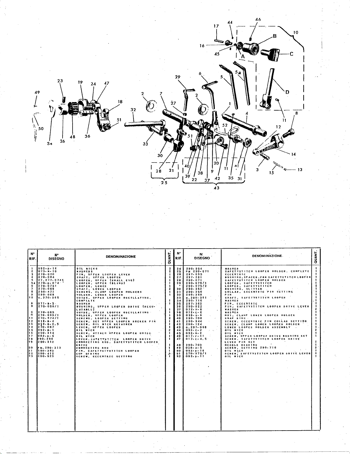
17
'\
i-
1.·~
16
~,·.~
45
•
0:!'~c
-;.
~·
I
I I
49
.....
/
.
,.,
.
..-:.-·
1~\
..
50
i!
t'
1
3.-.
26
48
19
36
47
:
fL
14"'-o
I
__
;.-
:
I
I
8
121\
I
h-·.~
3
43
if!
r-.
3
15
..
....
--13
N'
RIF.
7
9
10
c
n ~70-0D3/t
II
I 2 0 I
13
14
15
16
11
IS
19
2.0.
2-l
22
~3
2
3
4
5
SA
6
8
I
092•P•16
073.
N•
270·
070
no.oG4
27
..
2.77-0745
270•0•
270-0751
270-069
Z50·471
290-068
o-.270·065
071·e·S·
270·056/1
270·065
270•
!]7.4/l
6·
1!!1•
016·•·2.5
270·067
092·8·1
250.314
osz
.. o-s·
90·298
290·312
PM
..
290•JI3
2.90-363
290
..
412
290
..
923
DISEGNO
10
(174
4
LE;VER
SET
LEVER
• I
,.:
z
c(
::::>
0
·1
~I
I
I
I
I
I
I
J
I
I
I
I
2
I
I
I
I
2
I
I
f
1
2·
I
1
I
,.:
N"
OIL
WICKS
WASHERS
PIN.
UPPER
SHAFT.
~OOP£R§
·"
LOOPER • UPPER
~DOPER,
SHAFT,
SCREWS,
HOLDER.
GUIDE.
COMPLk.TE
WASHER
BUSHING,
I.ATABLE)
GUID~.
HO~PtR,
SCREWS,
SCREWo
SCR£.,
LEVER,
01'-
WICK
SCREW,
OIL
WICK
lEVER,
CONNECTING
DRIVE
CONNECTING
PIN,
5AFETYSTYSTITCH
CUP
SfAING
SCREW,
DENOMINAZIONE
LOOPER
LOOPER
LOOP~R
LOOPER
~OOPER
UPPER
WICK
LOOPER
R~U.
ROO
~EVER
{SMALL
{tJl
..
IHp)
LOOPER
LOOPER
lOOPER
LOOPCA
SETTING
LPOPER
RETAINER
UPPER
SAFETYSTITCH
SETTING
EY~)
HOLDERS
OSC.ILLATING,
DRIVE
OSCILLATING
LOOPER
LOOPER
LODPE·R
UPPER
UPPER
LOWER
LOWER
CLAMP
LdWER
UPPER
UPPER
UPPER
UPPER
LOOPER
SET
OIL
UPPER
ATTACH
J:AT~":''!"ST!":':;:H
ECCENTRIC
ROCKER
(R[GU•
GUIDE
DRIVE
LOO~ER
PIN
z
~
0
2
2
I 2 6
1 n
I
1 2 9
1
2
I 3 I
1
I
I 3 8
1 3 9
2
I 4 I
I 4 2
I
2
I
I · 4 6
I
I 4 8
1
1 <
..t-
· 5 I
I
w
RIF.
24
25
28
30
32
33
34
35
36
J1
40
43
44
45
47
4.
50
52
N
DISEGNO
Z9D·954
PM
290•071
297·
055
297·281
HO·
071
2~0·
075/1
290·
075/2
290·
352.
290·356
290·
360
0.~90·361
290·716
297·
362.
290•022
0 7
2•
II• 6
OH•C:C·
e
059•G•6
2~0·700
290·
944
290·
124
G,
297•
068
092·c~2
092·8·2
0 1 7 • F • I 1
Ol7·c
..
4.5
290
..
703
028•
A•
5
092•0•
16
270·
..
975/1
09
2.
o
..
I I
OENOMINAZIONE.
WASHER
S"AFETYST
ECCENTRIC
!!USHING,SP.ACER,FOR
SAFETYSTITCH
l.QOPER,
I,..ODPER,
8
US
COLLAR,
P
SHAfT,
WASHER
PIN,
PIN•
WAStiER
WAS
NUl,
SNAP
SCREW,
SCREW.
LOWER
OIL
OIL
SCREW,
SCREW,
l.EVER
NEEDLE
SCREW,
OIL
SCREW,
D
ITCH
LOOPER
HOLDER o COMPL.E·TE
SAFETYSTITCHLOOPER
!,..DOPER
SAFETYSTI:rc.H
SAFETYSTITCH
H I N G o
s·L
f T 1
ECCENTRIC
IN
SAFETYSTITC:H
ECCENTRIC
5AFET'I'S11TCH
II
t:
R I
Cl.-AMP
LOWER
R
lNG
ECCENTRIC
CLAMP
LOOPER
WICK
WICK
UPPER
LOOPEP
SAFETYSTITCH
PIN
SET
!tEARING
SETTING
wt.cK
SAFETYSTITCH
It.
WIcK
HOLDER
E.
D I
PJr.
SETTING
LOOPE.R
LOOPER
DRIVE
LOOPER
HOLDER
PIN
290·716
COLLAR
LOOPoEI1
ASSEMBLY
DRIVE
LOOPER
LOOPER
HOLDER
IIU.SHING
DRIVE
DRIV-E
LOWER
HOLDER
SETTING
Page 33
N•
RtF.
I
2
~
4
5
•
7
•
9
10
II
I 2
q·
14
I 5
6
I
I 7
I 0
I 9
270•13111
r
M'
Plto2.70•
no-·13·2
?70-
728
H0·027
270
..
933
270·713
2..70·006/1
073
f•
270
..
719
007
c
270o(J07/I
270·975/t
270·
'34
D•
092
071
E•
001
G•
210·
708
250
..
708
DtSEGNO
..
N"
13:7/1
9
t '
0 D I L
5
10
PIN
J.EVtR 0 NEEI)LE
IUSHING o NEEDlt
S II;
.,ASHtR,
N l,l
WASHER
SHAFT
WASH~
COLLAR,
SCREW.
LEVER,
SCREW.
P I
WASHER
SCREW,
llALL
NEEDLE
A£
,·,
H,
o
NEEOLE
W.,
POSITION
o
R
Ht:EDLE
WICK
IE.AR
SET
P~SITION
o
LOCK
NEEDLE
SECURE
CL-AMP
"NEEDLE
Ct.
AMP
SECURE
lNG·,
BEARING~
DENOMtNAZtONE
ROCKER
I.
EYER
fORk
LEVER
NE;EDLt-
a,.~VER
Nf;,Dl.E
AND
LOCK
OAR
CRANK
NEEDLE
2.
•••
DRIVE
WA;HER
NEEDLE
DRIVE
70·
07
•••
COLLAR
270·007/1
•••
NEEDLE
·PIN
"OCKER
NEEDLE
•••
I
DRIVE
P j N
A
OCKER
GU
I 0 E
OAR
GUIDE
CRANK
.SHAFT
7,1 g 2
E • 5 I
SHAFT
C
fl.
AN
K
LEVER
...
•
,.:
~
8
I
I
I
I
I
I
I
I
2
t
I
I
I
I
.I
I
I
N"
RtF.
20
.n
A
•
22
23- :
24
25
26
27
20
29
30
3 I
32
33
34
N"
DtSEGNO
250·
708/f
.
ore
••
2.
G.297•0Z5
290•
OH
290·
02SII
27
:
RIM
2.90·
944
:no-130
. 0 9 2
o • I
: 0 I 6
•·
2.
270•
IU
••
5
ou
UO·
133
017
c.
3.
001
<·1
270ol!
I
092
u.
1 r 0 I L
092
A• I 0 0 I L
DENOMtNAZtONE
i
8
N [
['D
l E
lEAR
REQUEST)
I 0 N
5
5
~
SCREW,
HEEI)L!
NE~DLE
NEEDLE
NEEDLE
5
CREW,
PI
H'
0 I L
WICK
SCREW.
LEVER,
OIL
'If I'C K
PI
H,
SCREW,
$CREW·,
WASHER,
WIcK
WICK
SECURE
GU I 0 E
HOLDEfl
GUIDE
RIM
HEEDLL
NEEDLE
0 I L
NEEDLE
NEtDLE
NEEDLE
RETAIN
RETAIN
NEEDLE
AS5[Mil.Y
RETAINER
DRIVING
D
DR I Y E
CHU~K
DRIVInG
II
IV
I
lEAR
•EA
LEVER.
SHAFT.
.•
.C~MPLifE
LEVER
SHAFT
H~
lNG
..
INQ
lNG.
NE'EDLE
lAO
I AR I
27
SET
HOLDER
WICK
HOLDER
HOLDER
HOLDER
NEEDLE
NE~DLE
HT
I
•
I
~
I
I
I
2,
I
'I
.I
t·
I
I
I
.J
•I
'
i
I
i
!
I
i
!
Page 34
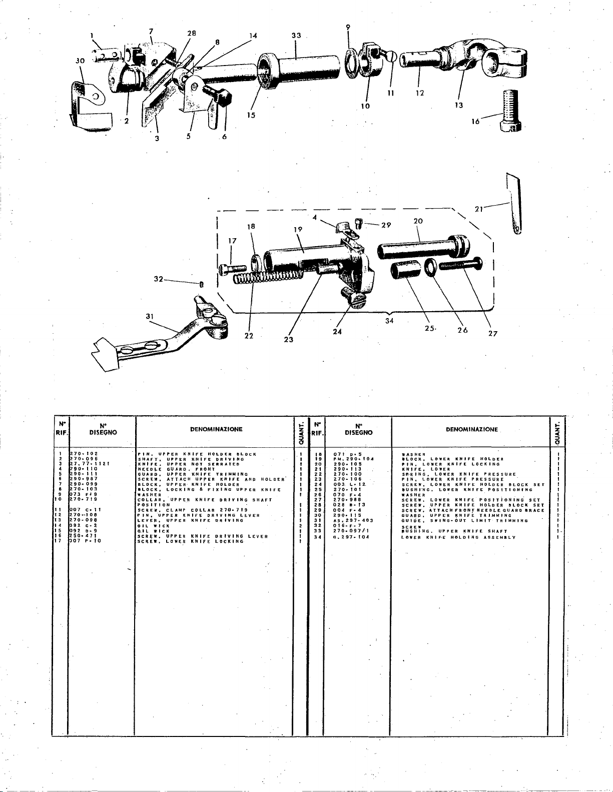
---~~~~u
""'
I
I
I
I
N"
RIF.
270-.102
I
l70-096
2
~
3
2 9 g
4
5
6
7
<90·
2.
8
9
~~~.~~,:
I 0
II
~07
I 2
I 3
210·
I 4
~92
I 5
I 6
~,so-
I 7
DJSEGNO
7. 7 7•
..
1 I 0
90~
I 1 I
90·
987
099
70·
10
C•
70-~108
09e
c·
92 0-9
•
11
07 P ..
N'
1 1
2.
I
3
II
a
I 0
-
P 1
H.
SHAFT,
K H f
FE,
Nf:ED~E
GUARD,
SCREW,
&LOCK,
BLOCK,
WASHER
COLLAR,
POSITION
SC R E.i',
P
IN
o
LEVER.
WIC-K
0 I L
O.ll
WICK
SCR~W.
SCREW,
liP
ATTACH
UPPER
LOCKING
CLAMP
UPPER
UPPER
UPPER
LOWER
I"'ER
U
I'
PER
UPPER
GO A R
UPPER
UPPER
KNIFE"
D,
KNIfE
DENOMINAZJONE
HOLU
ER
DRIVING
SERRAT£0
TRIMMING
KNIFE
HOLDER
FIXING
DAlY
A R
270-719
OR
IV
lNG
OR
IV
PRIVIHG
LOCKING
D L
UPPER
lNG
KNIFE
NOT
FRONT
KNIFE
LIPPER
KNIFE
"
KNIFE
C 0
Ll.
KNIFE
KNIFE
KNIFE
lNG
L
DC
AND
f.
V
LEVER
K
HOLDER
KNIFE
SHAFT
E.R
,..:
z
""
5
2
I
I
I
N'
RIF.
I 8
I 9
20
2 I
22
23
24
25 2 10
26
27
28
29
30
3 I
32
33
34
DJSEGNO
0 7 I
••
PM,
290•
~90·
105
290•
I I 3
210· I 00
2.
70-
1 0 6
t,.
003
..
I o t
••
070
2.70•
988
II•
028
004
F•
290~115
AS.297-403
0 t
6·
F-~
210·
097/1
G,
2.97"
SET
HT
SET
IIR-ACE
,..:
z
::::J
""
q
I
I
I
I
I
I
I
I
l
I
I
I
I•
I
I
1-
I
N'
5
104
..
12.
4
f 3
4
1
104
WASHER
.LOCK,
PIN,
KNIFE,
SP:·R
IN
P
IN,
SCREW,
eu
SH
WASHER
SCREW,
SCREW.
SCREW,
GUARD.
GUIDE,
SCREW
IIUSHING,
LOWER
I..
OWER
G,
LOWER
I'NG,
K N I F·E
LOWER
LOWER
LOWER
LOWER
L 0 W
UPPER
ATTACH
UPPER
SlfiNG-0Ur
DENOMINAZIONE
KNIFE
KNIFE
LOCKIN(l
KNIFE
KNIFE
PRESSURE
KNIFE
KNIFE
LOWER
KNIFE
ER
KNIFE
FRONf
KNIFE
LIMIT
KNIFE
UP
PEA
HOLDING
HOL b ER
PRESSURE
H 0
Lo
E R
POSITIONING
POSITioNING.
HOLDER
NEEDLE
TRIMMING
TRIMMING
SHAFT
ASSEMBLY
BLOCK
BLOCK
GUARD
i
;
I
!
Page 35
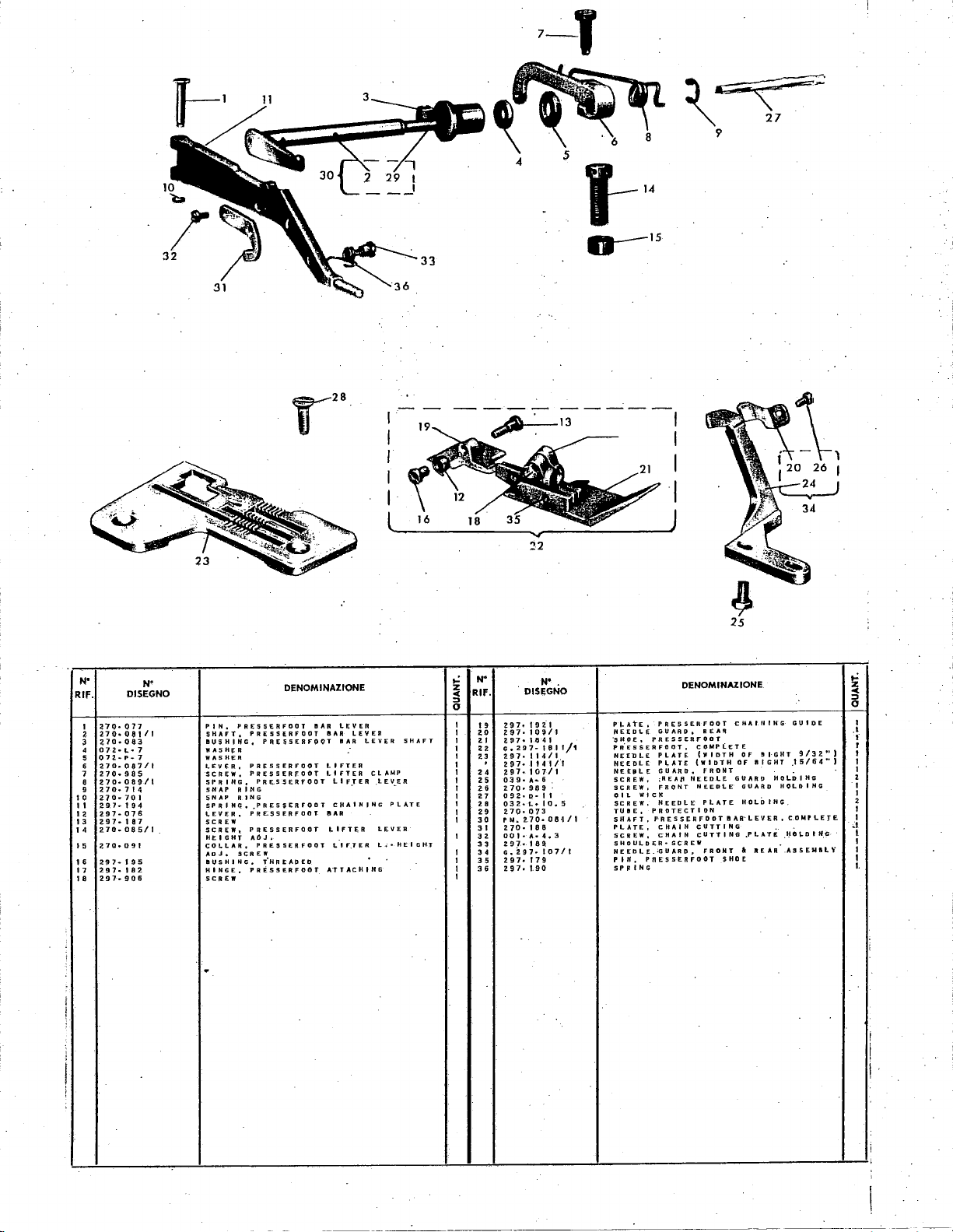
7-T
5
o--15
I I
I I
I I
I
I I
~~
9
""
27
N'
RIF.
I
2
3
4
5
6
7
8
9
I 0
II
12
I
3
14
I 5
16
18
DISEGNO
no-
011
210·
08111
Z70·08-3
072
..
1-•7
07~•P•7
270·087/1
270
..
985
270·089/t
270·714
270·701
Hhl94
2.97·076
297·187
ZHh085/1
270·091
297·195
297·
182
297·
906
N"
PIN,
SHAFT,
BUSHING,
WASH~
WASH~R
LEVER,
SCREW,
$PRING,
SNAP
5
NAP
SPRING,
I,.EVER,
SCREW
SCREW,
HEIGHT
COLLAft,
ADJ,.
I!IUSNING,
HINGE,
SCREW
.
PR£$5ERFOOT
PRESS~RFOOT
PRESSERFOOT
A
PRESSER
PRESSERFOOT
PRESSERFOOT
RING
A
IN
G
.PRESSERf"ODT
PRE.SSERFOOT
PRESSER
A6J,
PRESSERFOOT
SCREW
iHREADED
PRESSER
DENOMINAZIONE
L £ Y
•••
lEY
•••
•••
LIFTER
FOOT
LIFTER
LIF.TER
CHAINING
•••
LIFTER
FOOT
t. I F.T
A"TTACHING
FOOT
L~~------~-~----~J
N'
ER
LEVER
ER
ER
CLAMP
.LEV~ER
PlATE
LEVER
L.;•HEIGH:r
SHAFT
..:
z
co:
::>
0
RIF.
I
19
I
20
I
..
22
I
I
23
.
I
I
24
25
I
I
26
27
I
I
28
29
I
30
I
31
32
I
33
34
I
I
35
36
I
I
DISEGNO
297·
192.1
297·
109/1
297•1841
..297·1811/1
197·114/1
2n·
11411"1
297·
10711
0:3
g."
...
270·
989
0 9
~·
0.
032·••IO.o
2.70·
073
PM.
270·08·1/1
2
70.
18
DOI·A•4,3
z g 1
.•
1 a
G.
Z97•
297·
179
297·
1.90
N'
6
11
8
9.
107/1
.
Pl-AtE,
NEEDLE
~HOE,
PR.ESSERFDOT,
HEED
NEEDLE
NEEIILE
SCREW,
SCREW,
OIL
SCREW,
TUBE,
SHAFT,
PLATE,
SCREW,
SHOULDER•
NEEDLE.;GUARD,
P
IN,
SP
II
IN
PRESSERFOOT
GUARD,
PRESSERFODT
PLATE
LE
PLATE
GUARD,
;REA~
FRONT
WI C
IC
NEEDLE
PROTECTION
PRESSERFOOT
cHAIN
cHAIN
SCREW
PnEsSERFOOT
G
DENOMINAZIONE
cKAifHNG
REAR
COMPLETE
(WIDTH
Of
(WIDTH
OF
FRONT
GUARD
NEEDLE
NEEDLE
GUARO
HOLDING
PlATE
I!IAR·LEVER,
cUTTING
cUTTING
.PLAT£
A
FA
O.N
T
SHOE
B
a I G
REAR
GUIOE
I·GHT
.I
HT
HOL.D I HG
HOLDING
COMPLETE
):18
.ASS
9/3 2 ..
5/6 4 ''
~D
I
H.G
EMI!IL
l
l
'i
..:
z
<
::>
0
.l
"
I
f
r
t
I
I
2
I
I
2
I
I
I
I
I
I.
' I 7
l
I
!
:
l
!
:
i
I
I
i
'
Page 36

N"
RIF. DISEGNQ
I
2 PJ.to
3
4
5
6
7
8
9
10
II
I~
13
I 4 o3
15
lfi
17
18
19
20
21
42
23
24
Z70
..
941
2.7•
G,2.90·262./f
004
<··5.
n,o.
274/2
no.
264
2.7D··26S
270-265/1
2.70·
266
270·
268
a,~97
..
Ot&·a·-z.s
270·
271
6·
c-7
270·272
270·
170
r.M.
290·l53U
OOI·
c~
290·
2.70
270·942
290·
2.73
2.70·275/1
032.·
.... 6
2.70·2.32./f
5.
2.7
f71
N"
..
5
5
263
SCREYt.
TUBE,
NEEDLE
NEED
I.E
SCREW,
HEEPLETHREAD
UP,
TAKE
TUB£,
NEEDLE
GUIDE,
GUIDE,
GUIDE,
GU
J 0
Eo
lABEL,
SCREW.
NEEDL.E
THREAD
SCREW.
T
AK £ UP,LOWER
5CHEW,
IOfNTlfiCATION
1
AK
f.
Ur.,
SCREW,
ATTACHING
UPPER
LOOPER
$CREW,
GU I 0
E,
UPPER
LOOPER
S C-ft E
W,
SPRING,
NEEDlE.
THREAD
NEEDLE
THREAD
THREAD
THREAD
THREA~
I D
EN
GUIDE,
L 0 WER
LOWCR
UP P E R
THREAD
LOOPER
THREAD
LOWER
T t F t CArT t
DENOMINAZIONE
THREAD
TENSION,
THREAD
L 0 WER
LOOPER
L 0
OP
GUIDE
.d
GUIDE
l.OOPER
TENSION
O·N
TAKE
LOriPER
THREAD
(A
THREAD
TAkE
ATTACHING
GU I DE
HOLDING
TUPE
COMPLETE
THREAD
LAQ[l,.
TltACAO
THREAD
THREAD
THRt:AD
LOOPER
LOOPER
THREAQ
THREAD
SET
ATTACH
UP
ATTACHING
UP
TAKE
ATTACIIItiO
TAKE
IN~ I
UP 2
UP
..:
z
o(
RIF.
::>
0
I
I
I
I
I
I 3 I
2
2
2
I
I
I
I
I
I
I
I
I
I
I
I
2
N'
25
26
27
28
29
30
32
33
34
35
36
37
38
39
40
41
42
43
44
45
46
47
48
DISEGNO
270•
2-33
;no.
zap
603·
031
uo.
no
270··23212
004•N•5,5
290-
2.80
2.90-306
00A•G•7
,,.z.go
...
290-310
OQ4
..
A•2-.S
250·031
27·
PM
290·
255
?.9 0 •.
1.
!i 0
00
I"
r•
G•290•309/l
290·177
03Z•F•6.5
270·
643
a.70·730
065•
A•
297·214
N
JoB/t
27
6 .
6
...
..:
~
::>
0
3
3
6
3
I
I
I
I
I
I
I
I
2
I
I
I
I
I
I
I
I
I
I
DENOMINAZIONE
NG,
TENSION
SC
S,
W,
PI,.
INDICATOR
UPPER·
TENS I ON
TENSION
NEEDLE
NEEDLE
NEEDLE
NEEDLE
CAM
THREAD
THREAD
TENSI.ON
GUIDE
G U I
G U I
CAM
ATE
GUIDE
PLASTIC,
;rHREAD
GU I DE
DE,
f)(_
•
pI."'
AND
THREAD
THREAD"
PRESSING
r
TENSION
T.:AKE
CTHREAD
THREAD
TUBEBRACE
PRESSING
SAFETYSTITCH
SAfETYSTI
ATTACIIING
[
THREAD
ua
E
SPY
HOLE
CO V Eft
TAKE
UP
TUBE
SPRIN.G
TCII
GUIDE
HOlE
CAM
UP
AfT
AcHING
GUIDINGl
HOLDING
ATTACHI.NG
t. 0 OJ' E R I
LOOI"ER
COMPI,.ETE
I"ROTECTING
PUSitl
NUT,
D I
POSTS,
SPRING,
SCREW,
CONNECT I CN
BRACE,
SCREW,
PLATE,
SPRING,
SCREW~
253
D I 5 C 5 •
T.HREAO
THREAD
THREAD
1J
cRt
cAM
THR~AD
$CREW
OIL
PLUG,
WASHER
COYER,
...
_________
_
Page 37

----'·
68
16
59
53
I
Jl
--'
N"
RIF.
PMZ-O•lC·a/l
0 )
z
PNl9(loo_
3
~-:,"'
4
2"'7o.
~
270-983
6
f'M290•
007R~7.5
8
9
PN270~
'2..
7
10
?'JQ
II
032F
I 2
I 3
605-412
2JQaQ94
14
I~
270·701
I 6
;no
I 7
2'10·
18
~701J:•·092-
I 9
Z70a993
20
~70
Z I
270·066/1
..
026C·-12
23
02-ti"E~
24
026C•7
290·
H
PM270·095
26
:no
27
28
270·
29
270~940
30
PM?90•
,
270-972.
32
27.0·
33
270·
34
PMZ90·
35
270·970
36
HO·HI
37
0540·4
DISEGNO
..
·H•.!.
Z4
9
Q.
2 4
..
Q93
..
..
PBfi
018
..
995
247
..
o9o_
2-45
279
220
5
205.12
r.·z
ij
s-.•2
218.'1
24S/Z.
tj:
9,
10
210.
217
7
'Y~r
~~
//\
/
____
,
___
37•
,.
/
61
70
,.;
N"
0:0/tlle
S.::REW.
'/ER
RE'A~NER
·; 0
~·
E R
u::.
SP.
GA!'.iKE-~
S:RtW,
BAS~.
SCREW
r;ov
ER
GASKET
5
SCREW,
SCREW,
CAM.
LEVER,
SNAP
:IPRING,
PIN,
SPRING,
SCREW,
SCREW,
PI.UGS,
SCREW,
SCREW,
SCREW,
COV~R.
SHAFT,
SHAFT,
Pl,UG,
SCREW,
WORIIi
SCRtWo
SERVO
SCREW,
SHAFT,
COVER,
SCREW,
ATTACHING
SPRING,
NUT,
DENOMINAZIONE
NEED!.(
MOiEMEN-
liEEDtE
HO .. E
ANO
oJ~:.
SPY
COVER
Rt~AtNER
LOOPER
AND
I'RES!iERrOOT
STOP
CAM
STOP
PRESSERFOOT
AI
NG
PR[5'!JtftfOOT
PRF.SSERFOOT
PRESSERFDOT
PRESS!;:RFOOT
NEEDl.E
l.OOP
ER
FEED
MECHANJ
FEED
ME<;HAN·I
FEED
MECHANt
FEED
MECHANISM
PRESSERfOOT
PRESSERFOOT
FEED
MECHANISM
PLUG
PLATE
ATTACH
I R
PLASTIC
LOOPER
LOOPER a TAKE
LOOPER A TAKE
LOOPER
~TOP
MD
lEMEN
CAP
HOl.E
TAKE
PR£55URt;:
SET
RELEASE
BAR
MOVEMENT
SHAFT
MAIN
OIL•COVt;R
&.
TAKE
AND
ASSEMB-.
ASS£MB~
AND
UP
RELEASE
RlLEA5l
PRI;SSURE
Lf;VER
COVER
SEAt.
SM
COYER
SM
SEAL
$M_
C()VER
rRESSURE
LIFTER
SEAl.
CASTik~
UP
COVER
UP
UP
COVER
TAl(£
UP
;:;AP
COYER
NEGULATING
LEVER
LEVER
SHAFT
ATTACHING
PLUG
ATTACHIN.G
PLUG
TO
COVER
f
OIL
HINGE
BASE
•:D•
STOP
At•
z
~
0
,.
N•
RIF.
38
39
40.
4 I
42
..
..
H
H
41
48
49
50
51
52
53
54
55
56
57
58
59
60
61
62
63
64
65
tie
67
68
69
70
7 I
N
DISEGNO
SCREW,
~~?i~J!i!42/2
0
2-8
£
..
I 0
270·212
00
I O• 6
ooto-4.5
270·
718
ot7E•4,5
270·030/1
290·973
270-715
270·129
270·731/1
270•
23
I
0 I
~0
S.A
270·913
270·214
057£
..
4
005M•
10
290
..
6-19
2-70
..
624
270·
623/1
005E·I3
GZ-90-216
Z97·
220
oo
r.
o• 1
290·203
290·2-04
290,.
209
290·
947'
290·950
270·17Z/I
004•L•B
270-030
COVER,
SCREW,
TEA
SPRING,
SCREW,
TACHING
SCREW,
TACH
COLLAR,
SCREW,
PLUG,
SCREW,
SERVO
SCREW,
tAP,
SCREW,
GASKET,
SCREW,
PIN,
$CREW,
NUT,
SCREW,
COVER,
GASKET,
COVER,
SCREW,
COVER
ANGLE,
SCREW,
GASKET,
GASKET,
COVER,
GASKET,
CASTiNG)
WASHER
PATENT
$CREW,
$CREW,
62
63
35
DENOMINAZIONE
ADJUSTING
FEED
MEeHAN
ISM
FEED
ATTACHING
lNG
LOOPER A TAKE
MECHANISM
WORK
WORK
PLAT£
WORk
PL.ATE
WORK
COLLAR
01
FFERENTI
ATTACH
I R
SET
HEf;PLt
QUID[
ATTACHMENT
FEED
LOOPER
WORK
PLATE
WORK
PLATE
MAIN
SHAFT
MAIN
SHAFT
UPPER
UPPER
UPPER
ASSEMBLY, LOOPER A T.AKE•UP
FEED
DOG
ANGLE
REAR
fRONT
CHAIN
FOR
LONG
LABEL
GASKET
01
ffEREKTI
COVER
COVER
PI..ATE
l.ATCH
LATCH
LATCH
PLATE
HOLDING
SET
Al
SHAFT
MAIN
CASTING
•
~Aft
SECURING
MECHANISMCOVERAND-FilTEf;
AND
T.,.K E UP
UP
COVER
STOP
STOP
SCREW
COVER
KNifE
SHAfT
kNIFE
SHAFT
KNJ
FE
SHAFT
PROTECTION
ATTACHING
FOR
290•
209
FOR
291l•209
STITCH
LOOPER
SCREW
{ATTACH
Of'
MACH-INE
ATTACHING
Al
SHAFT,
AND
AND
SPRING
•
SPRING
SEAL
TO
COVER
SHAFT
ATTACHING
COVE"R
COVER.
A'SSEMIILV
S£At.
FILTER
OIL
•·
MAIN
f'IL
AT.•·
AT•
RE•
SET
,.;
z
~
0
I
I
...
I
I
'I
I
I
z
I
I
I
I
2
I
I
I
I
I
3
I
I
I'
2
I
I
I
I
I
I
Page 38

-----------
. /
_J
/
/
/
/
/
21
28
14
·~
-~
•c
29
D
c 18
22.
______
23
8
.,
N"
RIF.
•
•
c
•
E
3
4
5
6
7
•
~
I 0
II
I 2
13
I 4
I 5
I 6
17
I 6
I 9
zo
DISEGNCi
G270·816
270-911
PM270•
270~816
270.819
270·818
270-617
270-8;'0
PM270•821
PM270•
2.70·825
02.8
E•
00
I
r~
fl
2 7 Q .. 8 I 3
072M•7
G270-00I
270..-966
PM2.70·
270-970
270-947
0
5!;1 G ..
270-824
270..-815
2.70· 7 II
Z70·712.
818
6-16
I 0
6
N"
996/1
OIL
PUMP
PIN,
P9SITIONING
IIOUSING,OJLPUMP
HOUSING,
PLATE,
OIL
PLATE,
OIL
PLATE,
TUllE,
GASKET,
~CREW,
!it;RlW,
WASII(R,
WASHER,
Oil.
HE
WASHER,
PLUG,
SCREW,
WASHER,
NUT,
GEAR,
WASNER,
SNAP
OIL
Oil.
OIL
OIL
OIL
li[AR
SERVO
OIL
OIL
POSITIONING
OIL
RING
Gf,;.:i\R,
GEAR,
.GASKET,
DENOMINAZIONE
ASSEMBLY
OIL
PUMP
PUMP
PUMP
PUMP
PUMP
PUMP
TRANSPORT
OIL
TRASPORT
TRASPORT
AITACIIING
GtiiR
GEAR
I R
COMPLETE
OIL
DRAIN
DRAIN
PUMP
POSITIONING
PUMP
q_IL
PUMP
OIL
PUMP
COMPLETE
WITH
HOUSING
HOUSING
HOUSING
PLUG
Pl.-UG
ASSEMBLY
PIN
SEAL
POSITIONII~G
CQVER
'
TUBE
TUEIE
ATTACHING
LESS
OIL
PIN
PUMP
PIN
N"
RIF.
21
22
23
24
25
26
27
26
29
30
31
32
34
3 5
36
37
36
3~
40
4 I
42
43
DISEGNO
270·71Q
2.70·823
270·812
039~·10
270·82.9
PM270·830.
0041:,-
6
Ol7c
..
4.s
PM270•
270-808
270-946
27 0 ..
R I f
00
IE
..
1
PM27Q
..
270·
604
27Q.S05
PM
2 7 0 • 8
270·810
270·969
~70
..
814
2.70·001
2.70·706
06
5 L • 6
N"
826
80&il
0.5
DENOMINAZIONE
BAll
PEARING,
SHAFT.
WASHER,
SCREW,
GASKET,
T U
IE,
SCREW,
SCREW,
FILTER,
GA-SKET,
GASKET,
PIN,
MACHINE
POSITIONING
SCREW,
ATTACHING
8RACKET,
.
STICK,
FLOAT,·OIL
OIL
PULLEY,
~CREW,
FLANGE,
OIL
CUP
WASHER,
LEVEL
Rf;::SERVOIR
SPRING$
OIL
PUMP
POSITIONING
POSITIONING
OIL
0 I L F I L T
OIL
FILTER
OIL
FILTER
OIL
r.iACHINE
POS.ITIIJNING
OIL
LE'tEL
OIL
OIL
LEVEL
LEVEL
STICK
OIL
OIL
PUMP
OIL
P·OSITIONtNG
OIL
FILTER
BASE
LEVEL
PUMP
PUMP
PUMP
DRIVE
Eft
BASE
.STICK
AND
ATTACHING
WASHER
TUB.E
TUBE
ATTACHING
AND
PIN
TO
STICK
STICK
FLOAT
PIN
DRIVE
ATTACHING
01 L RESER
OIL
GUIDE
SH#.FT
ATTACHING
RrSERVOIR
BRACKET
GUIDE.
COMPLETE
VOl
R
I
.
I
~:
I
I
•
I
I
4
2
Page 39
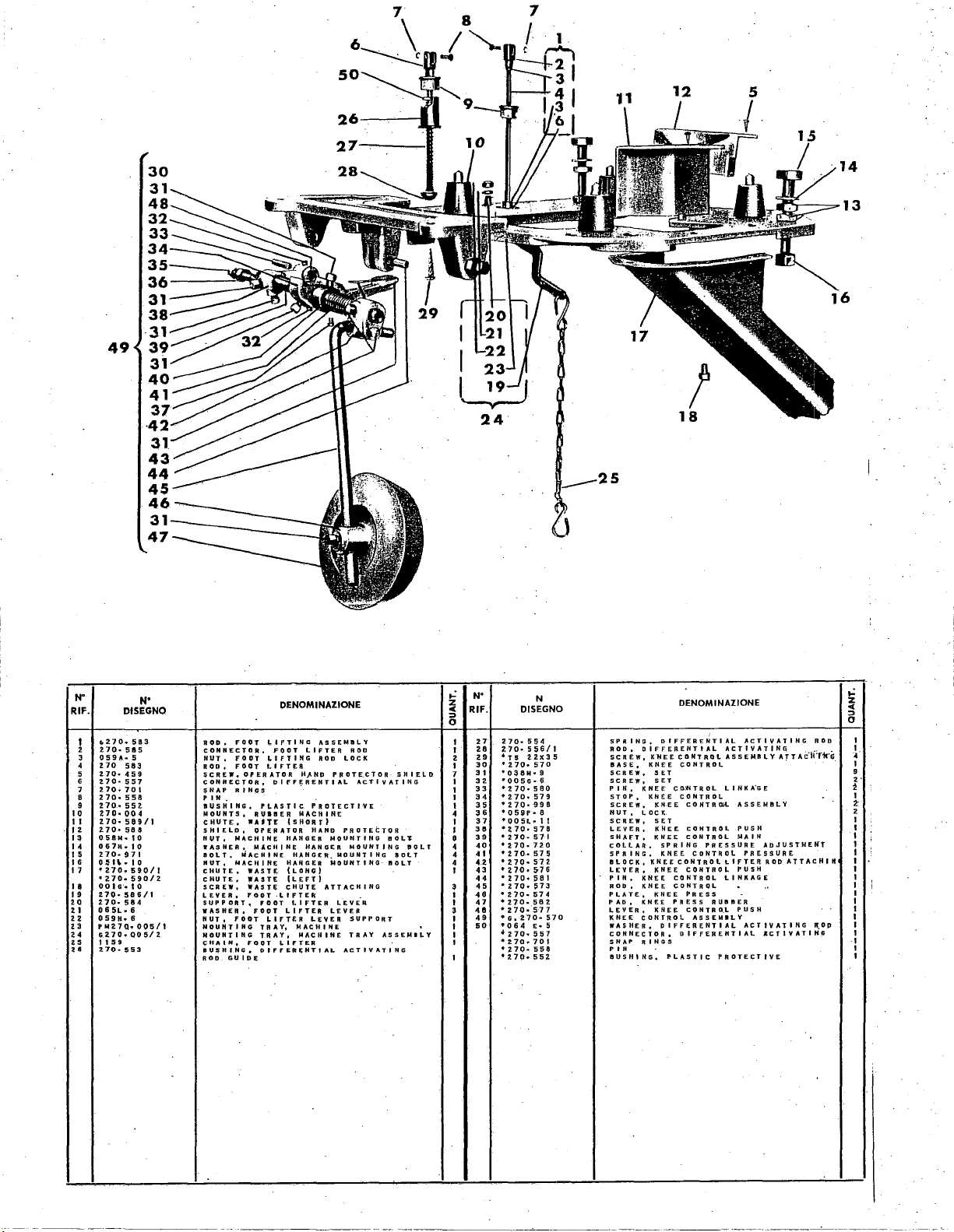
49
30
31
48
32
33
34
3
36
31
38
31
39
31
40
41
37
·42
31
43
44
45
46
31
47
27
24
14
13
18
5
N"
RIF.
I
2
3
4
5
6
7
B
9
to
II
12
13
I 4
u
16
I 7
I 8
I 9
2Q
2 I
22
23
24
25
••
N"
DISEGNO
o,Z70
..
583
210·
505
059A
..
5
2.70
583
270-459
Z70·S57
270•
701
270·
558
210·
55Z
270·
00
4
270·
5e9/l
270•580
058M·IO
067H•IO
270·
971
o~
n
.•
1 o
•
2.70
..
590/1
·~70-
590/2
00 I o·
..
I 0
210·586/1
270·
584
0 6
5L
• 6
059H•
6
PM2.7Q•005/1
oz70.QQ5/2
11
59
Z70•!!i53
ROD.
FOOT
CONNECTOR,
NUT,
FOOT
ROO,
FOOT
$CREW,
OPERATOR
CONNECTOR,
SNAP
RINGS
P I H •
BUSHING,
MOUNTS,
CHUTE,
SHIELD,
NUT,
MACHINE
WASHER,
BOLT,
~AcHINE
NUT,
NAC~IH£
CHUTE,
CHUTE,
SCREW,
LEVER,
SUPPORT~
WASHER,
NUT,
FOOT
MOUNTING
MOUHTIHG
CHAIN,
BUSHING,
ROD
GUID~
OENOMINAZIONE
~IFTING
FOOT
LIFTING
LIFTER
DIFFERENTIAL
PLASTIC
RUIBER
.A.T£
{SHORT)
OPERATOR
HANGER
MACHINE
HANGER
WAST~
(LONG)
WASTE
'LEFT)
WASTe
CHUTE
FOOT
-LIFTER
rOOT
LIFTER
FOOT
LIFTER
LIFTER
TRAY1 MACHINE
TRAY,
FOOT
LIFTER
OIFFER~HTfAL
ASSEMBLY
LIFTER
ROD
HJ.NP
.
PROTECTIVE
MACHINE
HAND
HANGER
HANGER.
LEVER
~ACHINE
ROO
LOCK
PROTE_CTOR
ACTIVATING
PROTECTOR
MOUNTING
MOUNTING
MOUNTING
MOUNTING
ATTACHING
.
LEVER
LEVER
SUPPORT
TRAY
ACTIVATING
SHIELD
BOLl
BOLT
BOLT
BOLT
ASSEMILY
..:
~
::>
0
I
I
2
I
7
I
I
I
I
4
I
I
e
4
4
4
I
~
I
I
~
I
I
I
I
I
N"
RIF.
27
28
~70·
29
•rs
30
'270·570
31
'038M•9
32.
'005G•
33
'270·
34
•270•
35
'2.70·
36
'059P•
37
'005t.·11
38
39
'210-571
40
'270·720
41
•2.70·
42
'270·
43 • 270·
44
•
45
•2.70·~73
48 • 270·
47
•z7o.
40
'270·
49
'Go270·570
60
•Of54 E ..
'270·557
'270
·~70·558
'2.70
DISEGNO
270·
·~70·
270·
..
..
N
554
556/t
azx3s
6
sao
579
996
6
578
575
572
5-76
581
574
sez
577
701
552
DENOMINAZIONE
SPRING,
ROD,
SCREW,
BASE,
SCREW,
SCREW,
P I H ,
STOP,
SCREW,
HUT,
SCREW,
LEVER,
SHAfT,
cOLLAR,
SPRING,
II
LEVER,
PIN,
ROD,
PLATE,
PAD,
LEVER,
KNEE
5
WASHER.
CONNECTOR.
SNAP
P I H
IIUSHING,
LOCK,
DIFFERENTIAL
DIFFERENTIAL
K"NEE
CONTROL
KNEE
CONTROL
SET
SET
KNEE C QlN
KNEE
CONTROL
KNEE
LOCK
SET
K~EE
KNEE
SPRING
KNEE
KNEE
CDNTR.OL
KNEE
KNEE
CONTROL
KNEE
CONTROL
KNEE
KNEE
PRESS
KNEE
CONTROL
DIFFERENTIAL
DIFFERENTIAL
RINGS
PLASTIC
ACTIVATING:
T R 0 L L I N K
CONTROIL
cONTROL
CONTROL
PRESSURE
CONTROL
LIFTER
CONTRO~
LINKAGE
PRESS
RUIIIIER
CONTRO.L
ASSEMILY
PROTECTIVE
ACTIVATING
ASSEMBLY
A'G
AS.SEMBLY
PUSH
MAIN
PRESSURE
PUSH
• .•
PUSH
ACTIVATING
....
AJTAc'itTk'G
E
ADJUSTMEKT
ROD
ATTACH
acTIVATIN~
ROD
~Op
I
I
•
I
9
2.
~
I
:1:
2
I
I
I
I
I
IN
I
I
l I
I
I
I
I
I
I
·I
I
I
Page 40

35
N>
RIF.
1
2
3
4
5
ij
7
8
9
10
I 1 0
1~
13
14
15
tG
17
18
19
20
21
22
'053•H•8
DISEGNO
("
9 Q .. I 3 4
Ot6•F•5
Z90
..
f4Q
.,...290.14a/l
2.90
..
137
250-143
290'
130
G,~90•137
114
6
290.142
IIi
5·
N•
6
oo1-•-1a
270-158/t
G,.%90oif57
ijQS,
QGO
609
..
937
AS.
290·140
TS
20X30
569
PM
910.~14
910
..
964
~
34
33
37
31
2
30~
~
2
._:
N"
RODo
SCREWS,
8R~CKET,
flOP,
THREAD
ROD,
.THREAD
ROD,
ROD.
THREAD
PIN.
BASE,
WASHER
SCREW,
ROD,.THil!AD
BAS[,
SCIU"WS
IRACitET,
THREAD
SCREW.S,
PAD
THREAD
rtDAL
NUTS,
~~~~:=o.
DENOMINAZIONE
THREAD
GU~OE
THREAD
QUID£
THR~AD
GUIDE
GUIDI;
ROD
GU,DE
MAIN
LOWER
MAIN
UPPER
GUIDE
THREAO
PR[SSERPOOT
PRES"SERFODTLIFTERLEVER
ASSEMBLY
SPOOL
THREAD
$POOL
MAIN
LOWER
$TAHp
A$SEN8LY,
S'OOL
ROD
TltRt:AO
R9D
LIFTER
GUIDE
THREAD
l.OWlR
STAND
WOOD
PRE.!S~R.·FOGT
ROD
~OD
SUPPORTING
SUPPORT
-HOLDING
SUPPORTING
OUID.E
COMPLETE
LIFTER
HOLDING
ASSEMBLY
ROO
ATTACHING
LEVER
(UPPER)
(LOWER)
ATTACIIINn
.AT•
~
0
2
8
1
1
2
1
I
1
5
1
I
1
1
I
3
I
I
2
5
I
2
2
N"
RIF.
23
30
3 1
:3
33
34
H
36
37
30
u
40
41
24
25
Z6
27
28
29
2
N
DISEGNO
910·
934/1
G.910•914/1
290·135
290•7Dtl
2.90·705
4?0/2
9
10.
143
5
69
1146
00
I•
G•
2·7·0·
151
0 t
6•
F •
270·
158/1
so
D•
un
805·
980.
11H
91
o.
144
G • 4 9 7
01141
DENOMINAIIONE
·I!!IASE.
·pRESSERFOOT
PRESSERFOOT
COMPLE-TE
THREAD
GUIDE
NUT
CUP
HOLDER,
ROD,
PADS,
I 0
5.
:~=~~:~;:::,.:p::!o~~IASE
ATTACHING
THREAD
SCRE'/1~--(HEADLESS)
ROD~
IRACKET,
ATTACHING
SeRE~,
NUT
R0o,·UPPER
THREAD
BASE,
SPRING
MAIN
THREAD
THREAD
THREAD
.
NEEDLE
.
THREAD
GUIDE
THREAD
GUIDE
SUPPORT~
LIFTER.
SPOOL
ROD
GUIDE
GUIDE
THREAD
ASSEMBLY
THR!AD
RO'L•t;.S
.--~-
GUIDE
LIFT~R
PEDA~
ROD
SUPPORTING
ROD
SUPPORT
STANO
STAND
PEDAL
~SSEMILY
sUiPORT
SUPPORT
ROD
!III:AcktT
..:
z
:::>
"'
0
1
·1
2
1
1
I
2
5
5
s
1
1
1
1
I.
2
4
2
I
I
~~----------~----·------
Page 41
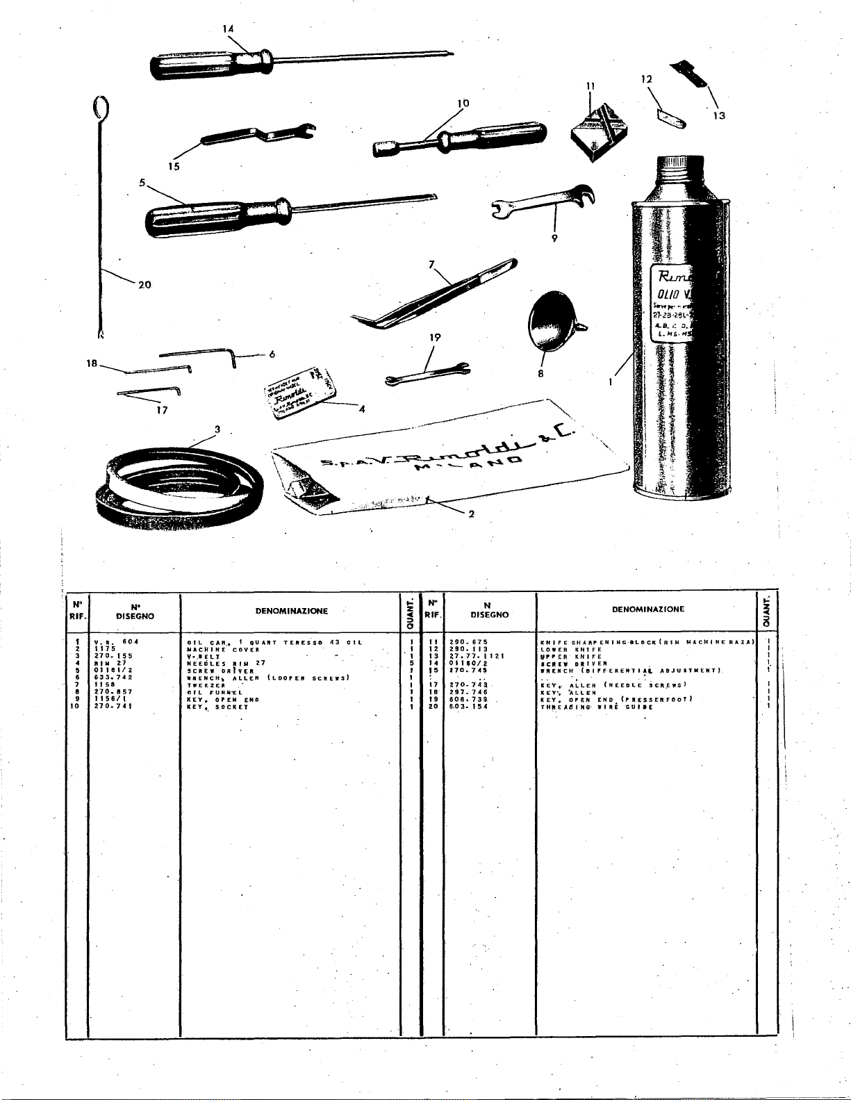
(
1.4
:
[~;o
11
~
12'
\,\
5
N"
RIF.
1
z
3
4
5
•
7
e
9
tO
y
•••
117
5
~7
0
..
RIM
01101/Z
633
..
742
1158
2.70~
1156/1
270.741
esw-:os
20
N•
DISEGNO
604
15
!;i
zj
8
57
0 I L
NACHIHE
V•.l
EL
NEEDl--ES
5Cft[W
WRENCH
TWEEZER
Oil
FUNH"El
KEY,
KEY'·
c
""··
COY
T
RIM
DRlYE-R
..
ALLEN
OPEN
SOCKET
DENOMINAZIONE
I
TERES
OU
Aft
T
Eft
Z7
(LOOPER
•••
SO
SCIIEWS)
43
0
ll
.
19
·~
..:
N"
z
c
RIF.
::>
0
;a90.
I
II
1 1 z
29 0 ..
n.11.
1
13
5
14
0 I
J70~7.C$
I
!5
I
17
z7o.74a
I
I t 8
Z97.7H
608
I I 9
zo
6.0 3-I
I
DISEGNO
675
1 I 3
UO/
..
739.
!:j,
N
1121
Z
4
9
KNIFE
.LOWER
VP
PER
ICR
WftENCH
KEY,.
KEY',
KEY,
TH!'EAtJ
DENOMINAZIONE
SHAftP
EN I NG·BLOCK
KH 1 FE
KNIFE
D
J1
IV
E R
~·
tDI,.FERENTI~i.
(NEEDLE
ALLEN
"ALLEH
OI"EN
I NG·
END
WIRE
(I"IIESSERFOOT}
GUilE
(RIM
ADJUSTMENT)
;Cft:.E'fi'S)
MACHINE
RAZA)
..:
~
8
I
I
I
I
I
I
I
I
I
i
------------·------·
Page 42

2
4
\
N'
RIF.
I
2
Z!O
...
2.10-051
N'
lliSEGNO
050
fEf;D
FEED
DOG•
DDt;•
llENOMINAIIONE
FRONT
.REAli:
...:
~
8
I
I
N'
RIF.
3
•
DISEGNO
H0-11411
ao.
•
@B.23.0
N'
111
NEEDLE
\.AIEL
PLATE•.
MACHINE
•
·~)~
llENOMINAIIONE
.,
IIGHJ
WIDTH
IDEN-TI
fl
CA;fl
ON
·')'/32
~
8
I
I
----
---
-----
-----------
---·
---
Page 43
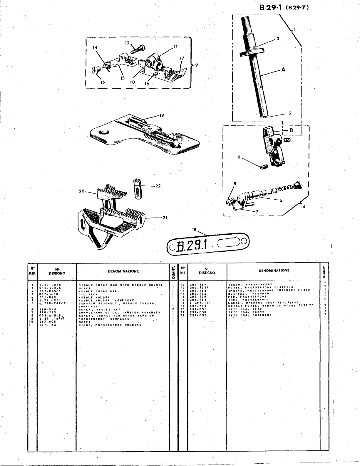
. I
9
I
2
----,
--.
..-;-a
D--
I
--·-l
I
I
I
I
I
I I
il.<\s~/Q:
I
~·
....._
___
~
7
__
·•
N"
RIF.
I
G,29f.0~5
OI6•A•2,5
2
297.02.5/1
•
0
- 3
291.0~0
I
c.Z91.020
4
o
5
zto
6
210.
7
:o~gt
9
'
I 0
2!7·
II
2.97•
9 2
.•
290
DISEGNO
..
A- I 0
..
94-4
280
906
I fl
N'
..
262/t•
~8~/1
2-
NEEDLE
SCREW
NEEDlE
OIL
WICK
H
E.E
D l £
.NEEDLE
TE.H·SION
COMPL.ETE
~c R £ w •
CONNECTION
SC
ft E W ,
PltESSERFOOT
sc
ft
[.
HINGE,
DENOMINAZIONE.
GUIDE
•••
GUIDE
BAR·
HOLDER
HOLDER,
.C.SSEMILY,
HEEtli.E
G
\1
CONNECTION
COMPLETE·
P
JtESSERFOOT·
COMPLETE
S.<T
IDE.
WITH
NEEDLE
TENSION
GUIDE
HOLDING
HE
ED
L E
THREAD,
ASSEMBLY
TENSION
HOLDER
..:
z
::>
"'
0
I
I
I
I
I
'
'
2
I
I
I
'
I
N"
RIF.
2
I
13
...
I
5
'6
17
'a
'9
20
zt
22
DISEGNO
297·
'87
297.1921
2.9 7
..
'! 4
297·
195
297·
179
29
t
..
I 8 4
Z9
I. I 71
I
t 9
I.
I I 4
2 9 t • 0 s I
zgr,oso
291·052
N·
S
Cft
E W
·•
PLATE,
SP
R I
N..G,
BUSHING,
PRESSERFODT
P
IN,
SHOE
l.
AIEL
NEEPL·E
PDG,
fEED
D 0
rEED
FEED
DOG.
PRESSER
PRESSERFOOT
PRES.SEAFOOT
THREADED
f'RE5$E'RFOD·T
MACHINE
I
PLATE,
REAR
G·,
FRONT
CHAIN
DENOMINAZIONE
FOOT
cHAINING
CHAINING
IDEN"TIFICATION
~I
t N
D T H'
G-
OF
liGHT
PLATE
5/
3'2
. .
..:
z
::>
"'
0
I
'
1
'
'
I.
I
....
' I
I
'
Page 44

B
29·18
(829·7>
-
......
I
I
I
8
12
I
I
_---
~~1;-~-
I . .
I
,
__
I M L
18
~~~:r,
. •
1s
-11
II
L=:
A,
I
I
I
23
___:.---
-~-
I
L
I l
~
22
I
RIF.
I
2
3
4
5
6
7
8
9
I 0
tl
'2
A
N"
DISEGNO
DENOMINAZIONE
SHOt. p RESSERFOOT
PIN,
PR:::::~::~OT
HING-E,
=~=!~NG,
SPRING,
SCREW
TENSION
PRESSEAFOO
SCREW,
;;~~~~
N E E·D.L E G U I 0 E
T~:~~:::ot
PR
SSEMBLY,
A T
·=~SSEO.OOT
:UIDE
COMP"I.ETE
sStRF'ODT
=~:
S~oi
HOLDING
SHOE
NEEDLE
ANGLE
GUI=~EOLE
WITH
THREAD
STOI"
STOP
HOLDER
I
..:
N"
~
RIF.
I 3
I
I
•
I 4
'
'5
'
I 6
17
'
'
'8
'
'9
I
'
20
I
.
2 I
I
22
I
23
I
..
2
9'.
G
291
..
0 0 4 •
G
290
290·
2.9.0
..
zgr
..
zgr
..
,.,
29
zgt..,OS:l
B • 2 9
ote.
09.2•
N'
DISEGNO
0 2.0
020
C•
5 5
...
262
280
9 4
.t
a.tt-t
e.oso
.os•
1
I..,_
f 7 I
A•
z. s
A•
to,
I
NEEDLE
NEEDLE
rt
SCREW P RESSERF'"OOT
~~:~~~;lpNDl~I~~TTING
SCJtEW,
Nt[Dl,.E
FtE['I
DOG•
f'EED,DO~~
~~:~~~OM~CHJHE
$CREW
oiL
wr
DENOMIN.UIONE.
HOLDER
HOLDE~
NE~TE
PL
FRONt
REAR
CHAINifi:G
cK
WITH
•
WIDTH
IDEN,
TENSION.
NIHG
CHAI
BIGHT
or
"'lffCATIDH
.
5/32
1-;.l
z
<C
8
r-
I
I
I
I
I
>
I
I
I
I
I
I
I
;
...
Page 45

IV.
NUMERICAL
INDEX
OF
PARTS
No
part
RIM,27
001A.4,
3
OOIC-5,5
0010.4.5
OOID.6
00
ID.7
001E.6
001E.7
001E.8
OOIE.IO
OOIE.18
0010.10
5
88~t:h
004A.2,5
004A.5
004C.5,5
004F.4
0040.7
004L.6
004L.7
004P.4,5
004P.6
004L8
8m:h
0050.6
005L.11
·no5M.7
005M.IO
007C0070-25
007P.IO
007R.7
OIOH. d S
016A.2,
0168.2,5
0168.4
016F.5
016F.IO
017C.3
OI7C.3,5
OI7C.4,5
OI7E.4,5
0
017E.8
017F.ll
026C.7
026C.12
026E.IO
028A.5
0288.5
0288.13
028E.10
032A.6
032F6,5
mE:h~5
036C.7
038C-7
038111.9
039A.6
039D.4,8
0390.10
0390.9
039R.8,5
051L.IO
053D.4
0530.8
054D.4
057A_3
057E.4
0570.4
057P
058M.IO
059A.5
0590.6
0590.6
059P.8
064E.5
064D.5
064F
064L.5
065A.6
065C-6
0650.6
065L.6
065N.6
0670.10
0708.3
071JF.4
8tV~J·
071D . .,
071E.5
0710.5
071M.5,5
072C.6
07211.6
072L.7
072M.7
072P.7
073A.8
073C.8
073F.9
8HM:I8
074A.12
Q9~t..l0
0928.1
092B.2
092C.2
092D.5
092D.6
092D.9
·
5
11
5
1·
17E.7
•.
5
..
5 3
5
table
5.13
7
9.26
8
8
8.17.18.20.21-
24.25
9.17.18.20.21.
24.25
.
·5.10.18
10
2
1
5.11.12
3
6
9
26
9.15.16.17
6.19.20.21
9
10.17.18.20.21.
24.25
3
26
3
8
9
8
11.17.18.20.2L
24.25
3.11.17.18.20-21
24.25
19.20
8
3.5.7
8
~-19.20.21
2
5.16.17.19.20.21
4.5.9
4
12
12
2
5
~-3.4.10
18.25
3
4
3.8
8
8
3.4
17.18.20.21.24_
25
6
8.10
9
9
8
7
9
17.18.20.2L24.·
25
11.17.18.20.21
24.25
7.19.20.21
23
10
3
17.18.20.2L24.
25
11
17.18.20.21.24.
25
12
8
25
8
3
u-18.20.21.24.
II
II
4.10
11
11.17_18.20.21.
24.25
11.17-18.20.21.
24.25
17.18.20.21.24.
25
22
9
22
3
IO.ILI7.18.20.
21.24.25
12
II
3
3.6.17.18.20.21
24.25
--
3
4
6.19.20.21
5
s
3
4
4
7
10
7
3
3
5.6
2
12
~.I~.IC!.l7.U-
20-21
~-4-5
4_6
4.5
3.5
6
No
part
092D.l1
092D.12
092D.J4
·092D.I5
092D.16
TS.20 X 30
TS.22 X 35
VR.604
54(i
490/2
547
0;497
569
01141
01160/2
.gmv~
1032
a
1145
1146
1156/1
1158
1159
1175
4030/06
160.030
160-032
240.035
250.031
250.113
250.314
250.471
250.708
250.708/1
270.004
PM.
270.005/1
0.270.005/2
270.006/1
270.007/1
270.008/1
270-009/2
PM.270.009/2
270-010/1
21o.o12n
270.016
270.030
270.030/1
270.031
270-032/1
270.033
270.034
270.035
270.036/1
270.038
PM.270.038/l
270.039
270.040
270.041
270.042/3
270.044/2
270.045
270.046/1
270.047/1
270.048
PM.
270.049
270.056/l
270.057/l
m:m;t
270.060/1
270.062
270.063/1
270.064
270.065
270.066/l
0,270.065/1
270.067
270.070
270-073
270.077
270.078
PM.270.081/1
270.081/1
270.083
270-085/l
270-086
270.087/1
270-089/1
270.090
270-091
270-093
270-094
PM.270.09S
270.096
270.097/1
270-098
270-100
270-102
270.103
270-106
270.108
270-116/2
270-129
270-130
270.131
270.132
270.133
270-134
270.135
PM.270.137/1
PM.
270.138/1
270.155
270.157
270.158/1
270.170
8.270.172/1
270.188
PM.270.205/2
PM.270-208/2
270.212
270.214
27!'-221
270.226
270.230
270.231
.270-232/1
table
4.5.7
3
3
2
3.4
18.25.26
11.17.18.20.21
24.25
13
22
12
22
12
12
12
.13
13.
8
U:U-20.2112
12
13
13
11
13
3
ll-"18.20.21-
..
25
2
.17.18.20.21.
2~_25
17.18.20.21_
24.25
9
12
4
3.4.6
5
5
11
11
11
5
5
2
2
2
2
2
I .
8
8
3
3
..
3
3
3
3
3
3
3
3
3
1
I
·3
3
.3
3
3
4
I
I
2
2
2
4
4
4
8
4
4
4
7
7
8~17.18.20.21
24.25
7
7
7
7
8
7
1
8
7
8
8.17.
U.
24.25
8
6
1
6
6
6
6
6
6
2
8
5
5
5
5
5
s
5
1
13
12
12
9
8
7
8
8
8
8
8
8
9
8
9
20-21-
.•
No
part
270.232/2
270-233
270.235
270.241/2
PM.270.242/2
PM.270.245/2
270.246
270-248
270.249
270.250/1
270.251/1
270.264
270.265
270.265/1
270.266
270.268
270.271
270.272
270.274/2
270.275/1
270.279
270.287/1
270.288/1
270.459
270.552
270.553
270.554
270.556/1
270.557
270.558
PM.270.562/I
270.566/1
270.567
270.568
270.570
0,270.570
270.571
270.572
270.573
270.574
270.575
270.576
270.577
270.578
270.579
"270.580
270_581
270.5
270.583
0.270.583
270.584
270.585
270-5
270.588
270.589/1
270.590/1
270.590/2
270.608
270-610
270.611/1
270.612
270.613
270.614
270.615
270.617/1
270.620
270.623/1
270.624
270.640/1
~~ua/1
270.643
270.644
PM.270.646
270.701
270.702
270.704
270.705
270.706
270.707
270.708
270.709
270.710
270.711
270.712
270.713
270-714
270.715
270.718
270.719
270.720
270.728
270.730
270.731/1
270.735
270.740
270.741
270.743
270.745
270.746
270.804
270.805
PM.270.805
PM.270.806/I
170.808
270.810
270.811
270.812
270.813
270.814
270.815
.
82
86/1
table
9
9
9
8
8
8
8
8
3
3
3
1.9
9
9
9
1.9
9
9
9
9
8
3
3
11
11.17.18.20.21
24.25"
11-11-18.20.21-
24.25
11.17
.18.20.21.
24.25
~l=~~-18.20.21.
11.17.18.20.21-
24.25
11
3
3
3
3
U:U-18.20-li.
1"1.17.18.21).21;
24.25
11.17.18.20.21.
24.25
11.17.18.20.2L
24.25
U:}~-•uut.
ILI7.18.20.21.
24.25
11.17.18.20.21-
.24
.25
11.17.18.20~21-
24.25
U:~~-18.20.21-
11.17.18.20.21.
24.25.
11.17.18.20.21.
24.25
11.17.18.20.21.
24.25
11.17.18-20.21.
24.25
IL17.18.20.2L
24.25
11
II
II
II
11
11
II
II
II
2
2
3
2
2
2
. 2
2
2
8
8
3
3.
I
L9
I
10
6.7.8.11.17.18-
20.21.24-25
3.17.18.20.24.
25
2
2
10
2
s
2
10
10
10
5
7
8
8
5.6
11.17.18-20.21.
24.25
5
9
8
3
13
13
13
13
13
10
10
10
10
10
10
10
10
10
10
to
.
I
0
----
·-------------
Page 46

No
part
270~816
Plll.270.816
G.
270.816
270.817
270.818
270.819
270.820
PN.270.821
270.823
270.824
270.825
PM.
270.826
270.829
~~o:Ag7s3o
270.911
270.912
270.913.
270.933
270.935
2i0-937
270.938
270.910
270-941
270.912
270.916
270.917
270.965/2
270.966
270.969
270.970
270.971
270.972
270.971/l
270-915
no-975'1
270.977
270-978
270.979
270.980
270.981
270.983
270-984
270.985
2
70.988
270.989
270.992
270.993
270.995
PM.
2.70-996/1
270.997
270.998
270.999
270.0541
270.0751
2700.074/1
27011.2470
270Y/.3220
27011'.3230
27011.3240
27011.3250
2701.3270
2701.3280
2701.3300
2701.3310
G.27011.3320
G.2701.3330
PM.27011.3330
27011.3330
27011.3340
G.
27011.3340
Pl\1.27011.3430
2701'.3450
27011.3460
270Tt'.3470
270Yi.3490
27011.3510
27011-3550
270VL3580
27011.3620
27011.3630
2701.3640
27011.3650
27011.3660
2701.3670
27011.3680
27011.3690
27011.3710
2701'.3720
m~:mg
PM.
27011.6400
27.01P.092
27.01P.403/1
PM.27.01PD.4!7/l
PM.27.01PDB.516
27.0JPDB.517
27.01PDB.518
27.01!'DB.519
27.
OIPDB.52t·
27.
OIPDB.558
2728.052
PM.27.26PDB0.1425
G.27.26PDB0.9375
Pl\1.27.27.253
PM.27.27-263
27.27.7.0745
27.77-196
27.77--1121
G.290.001
290.001
290.020
290.022
290.027
290.037
290.050
290.051
2!10.068
190.099
290.071
Pl\1.290.071
290.075/1
290.075/2
Pl\1.290.104
290.105
table
IO
10
10
10
10
10
10
10
10
10
10
10
10
10
10
10
1
8
5
3
3
2
8
9
9
10
10
8
10
10
S.IO
11
2
1
2_3
4_5
3
3
3
3
2
8
3
7
6
7.27
3
8
8
10
3
11.17.18.20.21.
24.25
2
3
4
4
23
23
28
23
23
28
23
28
28
23.28
23.28
28
28
.
28
23.28
28
28
28
28"
28
28
23.28
28
28
28
28
28
28
28
28
28
28
28
23
23
23
8
16
17.18.21.24.25
17.18.20.21.24_
25
17.18.20.21.24.
25
17.18.20-21.24.
25
17.18.20.21.24.
25
17.18.20.21.24-
25
17.18.20-21.24.
25
3
18.21:25
18.21.25.
9
9
4
7
6.13
10
10
5
4
5
3
14
14
4
6
4
4
4
4
6.19.20.21
6_19_2.0
No
part
N"
290.110
290.·111
290.113
290.114/1
290.115
290. I l4
290.130
290.134
290.135
290.13
7
G.290.137
290.140
AS.
290.140
290.142
PM.
290.148/1
G.
290-157
B.290.JH
290.177
290.203
290.204
PM.
290-20.5
290_209
PM.290-210
G.290.216
PM.290.217
PM.290_218/1
290-220
290.247
PAh
290.253/2
290.255
290.256
G.290.262/1
290.270/1
290.273
290.280
290.298
290.306
290.307
PM.290.309/1
G.
290.309/1
290.310
290.312
PM.290.313
PM.290.315
290.351
290.352
290.354
290.356
290.357
G.290.361
290.360
290.363
290.396
290.412
290.619
290.675
290.700
290_703
290.705
290.706
290.715
290.716
290.732
PM.290.732
290-733
290.734
290.916
290.923
290.944
290.947
290.950
290.954
290.973
290.987
290.3081
G.29011.2100
291.020
G.
291.020
G.
291.025·
291.050
291.051
291.052
291.114.
8.291.171
291.181
G.
291B.IB1
2918.182
2918.184
2918.186
2918.192
291PDB.050
291PDB.051
291PDB.ll0
291PDB.I14
G.291PDB.181
291PDB.184
G.291PDBO.l81
291PDBO.I84
G.29.17.002
29.17.020/1
G.
29.
29.17.050
29.17.051
29.17.104
G.
~g:H:m
29.17.114/1
29.17.132
PM.29.17.138
B.
29.17~171·
29.17.182
G.
29.17·.208/1
G.29.17.262/1
29.17.280
29.17.0501
29.17.0511
G.
29.
G.29.17.1811
29.17.1841
29.17.1921
29.17PDB.050
29.t7PDB.051
29.
17PDB.114
G.29.17PDB~181
G.
29.17PDB.I84
29
.17PDB_osot
29.17PDILOH1
G.29.17PDB0.181
29.17PDB0.184
G.29.174.181
29.174.182
?1
29.174.184.
·2
17.025
17~0761
table
6
6
6.13
14
6
4
12
12
12
12
12
12
12
12
12
12
H
9
8
8
8
8
8
8
8
8
8
8
9
9
9
9.15.16.17.18
9
9
9.15-16.17
.4
9
2
9
9
9
4
4
1
1
4
1
4
1
4
4
4
1
4
8
13
4
3.4
12
12
3
4
3
3
3
3
1
4
4.5.15.16.17
8
8
4
8
6
2
22
15.16.17
15.16.17
H:li-17
15.1
15.16.17·
15.16
15.16.17-18.
15
16
16
.
16
16
16
17.18
17.18
17.18
17.18
17
17
18
18
19.20.21
19.20.21
19.20-21
19
19
19.20.21
20.21
19.20
19
19.20.21
19.
20.21
19.20.21
19.20.21
19.20.21"
19.20.21
19.20.21
19
19
19.20.21
19
19
19.20
20
.. 21
20.21
~g-21.22
20
22
22
21
21
22
22
22
.
p.ut
.PM.
297.025/
297.050/1
297-051
297.055
G.2q7.068
297•076
297.107
297.107/1
G.297.107/1
297-109/1
297-114/1
B.
297-171
297-179
297.182"
297-187
297-189
297-190
2!17
-194
297.195
297.214
297.220
297.362
AS.297.403
297.906
297.1141/1
G.
297.1811
297.1841
2.97.1921
297PDB.050
297PDB.051
297PDB.114
.G.297PDB.181
297PDB-184
297PDB.401
G.297PDB.401
297PDB.402
297PDB.403
PM.297PDB.406
297PDB.407
297PDB=408
297PDB-418
297PDB.441
297PDB.442
297PDB.443
297PDB.444
PM.297PDB.515
G.297PDB.515
297PDB.l141
297PDB.4021
297PDB.403
G.297PDBO.I81
297PDB0.184
PM.297PDB0.413
PM.297PDB0.4131
297R.071/I
297R.267
PM.297R.267
297R.181l
G.
297R.I841
PM.29711.0760
29711.2470
297TI.3220
G.
29.78.107
29.78.114
G.29.78.181
29.78.184
29.78.191
~~3~8h
603.154
603.739
605.412
605.937
605.980
633.742
910.143
910.144
:
297.025
141/1
I
tabh
5
5.15.16.17.19.
20.21
3
3
4
4
7
19.20.21
7
7
7
7
9_24-25
7-15.16.17.18.19.
20-21-22-24.25_
26-27
7.15-17-18.24.25.
26.27
7_15.16-17.19-20_
22-25-27.
7
7
7-15-16.17.19-20-
22.24-25.27
7-15.16.17.19-20-
22.24_25.27
9
8
4
6
15.16.17.18.19_20
21.24.25~26.27
7.26
7
7
7.15.17.24.26.27
24
24
24
24
24
17.18.20-21.24.25
17.18.20.21.24.25
17.18-20.21.24.25
17.18.20.21.24.25
17.18.20-21.24.25
17.18.20.21.24.25
17.1P.20.21.24.25
17.1~-20.21.24.25
17.18.20.21.24.25
17.18.20.21.24.25
17.18.20.21.24.25
17.18.20.21.24.25
17.18.20.21.24.25
17.18.20.21.24.25
23
17.18.20.21.24.25
1
17.18.20.21.24.25
25
25
18.21.25
18.21.25
26
26
26
26
26
23
23
23
27
27
27
27
27
18.21.25
9
13
13
8
12
12
13
12
12
Page 47

83
B 29·1 PDB < s 29·7>
2
N'
RIF.
1
2.
3
4
5
DISEGNO
·lJQ.,S57
l]O
..
jOt
27.01PDfl•558
Z10·
5H
no.
553
N'
2-70·554
7
Z70·
556/1
T
~
s •
2-
ZX
B
9
I 0
II
1 z
13
1 4
I 5
1 6
17
1 B
19
zo
z 1
22
23
24
25
Z6
Z7
28
29
30
..
3 I A
32
3
3.
34
35
36
37
38
39
40
41
4.2
43
44
4S
••
47
005L•
~
0 6 4
GZ97PPIJ·
PM297PDB~
27
297·127
3 5
2.10·
570
Q38M·~
005G·
6
270·
580
270·579
270·998
059P•
8
11
Z70•
57
B
Z10•
57l
Z70•
7ZO
270·
575
270·
!i72
270·576
270•
581
70·
573
270
..
574
2.70·582
270-577
G270•
570
E•
5
SIS
Z97Pflft•
402
297Po•-
4DZt
27.UIPDB•
0.53D.,
070F•
270-702
27,.
2.7.
297PDIJ•
0~8C•
Z7.0IPPII•
~;j::;~DB•181/t
2.97·
297·1921
4
4
OIPDI'•
..
01PDIJ•519
OIPDB•
7
'94
401
SIB
515
517
SZP
~16
tDit.f,q;;cTOR,
SNAP R lNG
P I H
BUSHING,
BUSHING
GUIDE
SPRING,
.GUIDE
ROD,
DIFFERENTIAL
SCREW
•
.ASEo
$CREW,
scn£w.
P
I.N,
KNEE
STOP,
KNEE
SCREW,
NUT,
LOCK
SCREW,
LEVER,
SHAFT,
COLLAR,
SPRING,
fll.OCK,
LEVER,
PIN.
KNEE
ROD,
KNEE
PLATE,
PAD,
KNEE
LEVER,
KNEE
CONTROL
WASHER,
sHIRRING
ASSEMBLY
SHIRRING
SHIRhiNG
PIN
SHIRRING
hOT
WASHER
LEVER,
SNAP R lNG
YOKE,
SHIRRING
STUD,
LIFTING
PIN,
LIFTING
BASE.
SHIRRING
SCREW,
YOKE
ATTACHING
LINK,
SH~RRING
PRESSERfDOT
BUSHING,
SPRING,
HtNGE,
SCREW,
DIFFER(:NTIAL
P'LASTIC
DIFFERENTIAL
DIFFERENTIAL
WOOD
KNEE
CONTROL
SET
SET
CONTROL
CONTROL
KNEE
SET
KNE~
KNEE
SPRING
KN~E
KNr:r:
CONlROLLIFlf.R
KNEE
CONTRO~
CONTROL
KNEE
PRESS
KNEE
"CONTROL
DIFFERENTIAL
BLADE
COMPLETE
BLADE
lll.ADE
SH(RR~NG
SHIRRING
THREADED
PRESSERfOOT
PRESSERFOOT
PRESSERFOOT
DENOMINAZ10NE
PROTECTIVE
JC~17ATfNG
ACT.IYATING
ACTIVATING·
·LINKAGE
f;ONTROL
CONTROL
CONTROL
CONJROL
PRESS
ASSEMBLY
PRESSURE
CONTROL
LINKAGE
ASSEMBLY
LIFTER
(OFFSET)
(STRAIGHT)
Bl.ADE
LtFT£R
BLADE
I!ILA.DE
LEVER
LEVER
A.TTACHMiNT
&LADE
.LADE
ASSEMBLY·
PUSH
MAIN
PRESSURE
PV~H
PUSH
ACTIVATING
LEVER
LIFT.ER
LIFTER·
MOUNTING
ROC~£~
LifTER
LIFTER
COMPLET-E
SHIELD
~TTACHING
SHIELD
ACTIVATI.NG
ADJUSTM-ENT
liDO
AT.TA.CIIINI
LI~KAGE
i.EVER.HINGE
LEVER
.
KNEE
L~VER
:
SPRING
RDQ
ROD
ROO
79
-~r
ONLY
,.;
z
...
:>
0
·1
1
I
I
2.
4
1
I
I
2
I
I
2
I
.,
1
I
I
I
1
I
I
1
I
I
I
I
I
I
Z
I
i
,.:
N"
~
RIF.
0
RO
••
4S
50
52
53
54
I
1
4 Ss
I
56
9
57
2
2
59
I
60
2
61
2
62
I 6 3
1 6 4
I 6 5
I 6 6
I
67
1 6 8
I 6 9
1
70
I
I
71
1
1
7Z
I
73
I
74
75
1
76
1•
I 7 7
I
78
I 7 9
I 8 o
1 8 I
3
82
1
83
1
84
I A
1 .
85
••
B7
Btl'
eo.
90
51
58
•
-N
DISEGNO
29f•PDB•.f84
2 9 f
··P
b
~
•·.0
291•PDB•I
291•PQB•dJjt
Pf.A270
IPD·
G~97PDB•
297Poe-
403
2.97Ptie-40:lt
0 6
5L-
6
297PpB•·418
004L··6
uo'
t:
..
6
2.97Po.B··
407
297PDB.-
408
0
fj
40
..
5 .
0
57P
• 5
297PDB
..
444
297POI!I•
442
297Poa-441
0288·
s
270-078"
270·094
039R•B.!:i
I
03
2.
A
160~032.
297PDB•
443
240-035
160-030
PM297POB
00
I D • 7
2•91·05.2
t91/PDB•
B,
2 9 I • 1 7 f
297·18a
297-906
297·
179
G,291-02.5
016
A•2.5
2.97.-025/1
092•A•10
291•020.
Go~91•02.0
G.
2.90
..
2.62/
290•
944
2.90-.2.8
0
oo4-.c-5.5
DENOM1NAZ10NE
SHOE,
50
14
417/1
401
.
..
406
f
10
I
PRESSERFOOT
::::L:o;~A;;~ft~WIDiH
FEED
OOG,
SHIRRING
SHIRRING
sHIRRING
SHIRR
SHIRRING
SHIRRING
SHIRRING
SHIRRING
SHIRRING
L!ATCH
HOLDER
HOLDER
L I F T I N G
RELEASE
SIIIRRING
GUIDE
SHIRRING
HER
SHIRRING
SHIRRING
AT~ACHING
DOG,
GUARD,
PRE5SERFD0T
PRESSERfDOT
GUIDE
SET
GUIDE
'i
I
ex.
HQLDER
HOLDER.
THREAD
NEEDLE
REAR
AT.TACHMENT
lNG
LATCH
LATCH
SIIIRRING
SHIRRING
CHAINING
IDENTIFICATION
PRtSSERFOO"J:
IAR
BAR
GUIDE
BLECK,
SHIRRIN.G
SHAFT,
SHAFT0 SHIRRING
WITH
WASHER
SCREW,
SCREW.
SCREW.
LEVER,
&LOCK,
WASHER
NUT,
SPRIN(i,
PIN,
PLATE,
SCREW,
P
IN..
LATCH,
SCRCW,
BUSHING,
SP . .RING
NUT,
ADJUSTING·
SPRING,
W Jl.S
STUD.
LEVER,
SCREW,~SHIRRING
SLDCK
FEED
NEEDLE
I.·AI!IE(,
HOLDER,
SCREW,
PIN,
NEEDLE
SCREW,
NEEDLE
0 I L
NEEDLE
NEEDI.E
NEEDLE
SCREWS0 NEEDLE
CONNECTION
SCREW.
OF
!liTE
ATTACHMENT
ASSEMBLY
!!LADE
BLADE
BLADE
ATTACHMENT
PLATE
.BLADE
REAR
TAKE
HOLDER
(fOR
(297PDil•402.1)
ATTACHMANT
BLADE
ATTACHJNG
BLADE
SHAFT
B~ADE
PRESSURE
ATTACHMENT
ASSEMllLING
ATTACHING
ft
0 t k [ R I
LIFTER
ATTACIIMtNT
BLADE
PRESSURE
PRESSURE
BLADE
PRESSURE
BLADE
PRESSURE
BLADE
LlfT~R
ATTACHMENT
AND
·cHUCK.
COMPLETE
UP
COMPLETE
SET
5/32'').
RETAINER
COMiot._ETE
USE
ASSEMBLY
SET
MOUNTING
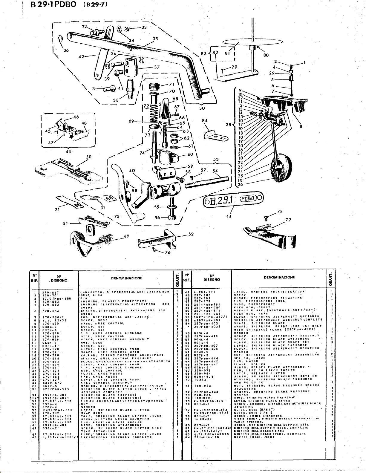
B29·1PDBO
(
829•7)
N'
RIF.
10
II
12.
13
lA
15
16
17
18
19
20
2.1
22.
23
24
2.5
u
27
2.8
29
JO
3f
lA
32
33
34
35
36
37
3B
39
.
40
:41
'
.42
43
I
2
3
4
5
1
8
9
'270-571
.DISEGNO
2.10.
557
2.70-701
27.0I"PQB•558
270-552.
2.70-553
270.
554
no-
556/1
To
s.
22.X35
270-
570
030M•9
005G•6
2.70·580.
270
..
579
270-~~6
059P•8
005L·II
2.70-578
?.70·
571
270·720
2.70-575
2:70-572
270-576
270·
58
2.70-
573
2.70-
57
270-562
G270~
570
064£•
5
G297PDB·
297PDB•402
2.97PQP•402.1
Z7.DIPDB·518
0530·
4.
070F·
4
PM2.97f'DD·5f5
270·702
27,01PDB•
27,0ff'DB-519
2.7.0fppa-52.0
2.97PDD•401
038c
..
7 •
27,01PDII•5f6
G,
291·-f'
N'
I
4
oaofat/t
44
__...--78
~7
~11
DENOMINAZIONE
(;ONNECTOR,
SNAP
PIN
BUSHING,
BUSHING
GU I DE'
SPRING,
GUIDE
ROP,
SCREW,
DASF.,
St:RtW,
SCREW,
PIN,
STOP,
SCRC.W,
NUT,
SCREW,
LEVER,
SH.AFT,
COLLAR,
SPRING,
8LOCK,
LEVER,
PIN,
no6,
PLATE,
PAD,
I.F.VER,
KNEE
WASHER,
517
5
SHIRRING
ASSEMBLY
SHIRRING
~HIRRfNG
PIN S HI
NUT
WASHER
LEVER,
SN.AP
YOKE,
STUD,
PJN,
BASE,
$CREW,
YOKE
LINK,PRESSERFOOT
Sf
R I N G
PLASTIC.
Dl
fFE.RENTI
DIFFERENTIAL
DIFFERENTIAL
WOOD
KNEE
SET
SET
KNEE
CONTROL
KNEE
kNEE
LOCK
SET
KNEE
KNEE
SPRINCi
KNEE
KNEE
KNEE
KNEE
CONTROL
K~EE
CONTROL
KNEE
KNEE
PRESS
KNEE
CONTROL
DIFF~R~NTIAL
BLADE
COMPLETE
PLAD'E
BLADE
A
II
IN
G 0
SHIRRING
Rl
NG
SHIRRING
LIFTING
LIFTING
SHIRRING
SHIRRING
ATTACHING
SHI
RAING
Dl
fFEREHTI
CDNTRO~
CONTROL
CONTROL
CONTROL
CONTROl.
CONTROl
CONTROL
CQNTRDL
PRESS
CONTROL
ASSCMBLY
LADEt. I FT
L,.VER
LEVER
ASSEMBLY
AL
PROTFr.:TIVE
At.
ACTIVATING
ACTIVATING
ACTIVATING
LINKAG,E
ASSEMBLY
PUSH
MAl
PRESSURE
Ll
FTER
PUSH
LINKAGE
PUSH
ACTIVATING
LIFTER
(OFFSET)
(STRAI\iHT)
BLADE
BLADE
MOUNTING
RDCkE.R
ATTACH'-'£NT
BLADE
BLADE
ACTIVATING
N
APJUSTMr.NT
PRESSURE
ROO
LEVER
E R
LEV
t.l
FTER
LIFTER
LIFTER
Ll
FTER
COMPLETE
.
ATTACHING
LINKAGE
.
E"R
HINGE
.
LEVER
KNEE
L~VER
ROD
ROD
ROO
ROD
44
45
46
47
46
49
50
51
52
4
53
I
54
9
2
2
55
I
56
2
57
2
58
I
59
I
60
I
6 I
I
62
I
63
I
64
I
65
I
6
6-
I
67
I
68
I
69
I
70
.I
I
71
72
73
14
75
16
11
78
70
80
81
8~
63
84
N'
DISEGNO
a.
Z9
1
..
I 7 I
Z97
..
906
297-162
297·179
Z9I•PDBOI84
29I•PPa•050
297•roo-114
291•POS·051
PM270IPD•
G297POB•401
297POB•403
297PDD•4031
0 6
SL
• 6
2.97P
oa:.
418
00
4L • 6
00
IE
• 6
297P
08•"407
Z97P
DQ
..
408
0640·5
057r.s
297PDB•444
297PDB•442
2.97P
DB•
441
02BB•5
270·078
270·094
039R•8,
5
1032.A
160-032
297P
09•.443
~40·03~
160·030
PM2.97P09•406
oo 1
-o-7
PN 02.97PDBD•413
PM297PDBCJ•4t31
00
I •
E•7
Ts
zox~.o
0
17-
t-7
PM
,2.7,2.6POBOI42
f'M,602·141/t
G.2.7
,26P
I•P.DB•IlO
oao937!!5
29
417/1
LABEL,
SCREW
HINGE,
PIN,
SHOE, P RESSERFOOT
FEED
NEEDLE
FEED
BLOCK,
SHIRRING
SIIAFT,
SHAFT,
WITH
WASHER
SCREW,
SCREW,
SCREW,
LEVER,
B L 0
CK
WASHER
NUT,
SPRING,
PIN,
PLATE,
SCREW,
PIN,
LATCH,
SCREW,
B
1J
S
HI
SPRING
NUT,
ADJUSTING
SPRING,
WASHER
STUD,
LEVER,
SCREW,
ATTACHING
GUIDE,
GUIDE,
SCREW,
WOOD
·TABLE
SCREW
BINDING
8
IN
D I H G
BINDING
NEEDLE
MACHINE
PRESSERFDOT
PRESSERFOOT
DOG,
·FRONT
PLATE,
DOG,
REAR
SHI
RRI
ATTACHMENT
SHI
RAING
SHIRRtNG
SHIRRING)
SHIRRING
SHIRRING
SHIRRING
SHIRRING
SHIRRING
,
SHIRRING
LATCH
LATCtl
HOLDER
HOLDER
LIFTING
REl-EASE
SHIRRING
N G , 5
HI
GUIDE
SHIRRING
SHiftRIHG
SHIRRING
SHIRRING
SHIRRING
CORD
(5/64'')
CORD
{1/8'')
GUIDE
SCREW,
BINDING
ATTACHG
•
,SET
BINDING
ROLL
SUPPORT
.RD
LL
H 0
ROLL
HOl.ER
GUARD.
DENOMINAZIONE
IDENTIFICATION
ATTACHING
SHOE
(WIDTHDFBtGHT9/32'')
HG
ATTACHMENT
AS.SEMBLYCOMPLET£
BLADE
ai..ADE
Bl.AOE
(297PD8•402.1)
ATTACHNINT
BLADE
ATTACHING
BLADE
SHAFT
BLADE
PRES
ATTACHMENT
ATTACHMENT
PLATE
ATTACHING
LATCH
ROCKER
LIFTER
ATTACHMENT
R R I H G
II
L
A.D
E P
BLADE
PRESSURE
Bt.AOE
BLADE
PRESSURE.
BLADE
LIFTER
ATTACHMENT
ATTACHING
HDLOER
ROLL
SUPPORT
DISC.
LD
E R B
AS
E
STAND.
FRONT
COMtLETE.
RETAI·NER
(FOR
ASSEMBLY
SURE
MOUNTING
ASSEMILLNG
SETTING
RES
PRESSURE
RETAINER
ASSEMBLY
DISC
COMPLETE
USE
SET
SURE
SPRING
ONLY
BLOCK
Page 49

r-
1
I
I
I
I
I
L_
1"
3,1
----'--
17
829·17
r
I
(829·7)
I
I
I
19
30
32
------~~:-f:.T--:-~=-----;-
----------,~---....:.--:::
• E
DENOMINAZION
'"
EftF
··::
..
t~::LETE
...
"
""
""':
-----
••
T
LIYTEfiOLE.
'""
NEE
.... ....
• '
....
...
"'"
......
....
...
:.
OOC'
""..
..
...
••
...
.
'"::.
::~
:·
......
.
HOLPER
""
.....
7
~
.. 2aB/1
""
..
"''
'"
1
_j
_____
'"'"'
'"'"
'"'"
5
...... : .....
C
,•:~=~•
:::
.............
;~:
'""•,,,,...........
'""
.....
. "
:::;
~~!~~ON
co••••n-
-:-::-:-:;-:--;-;
;::::
.......
......
PR~T
.......
.........
::. . . ,
,;,.,.,,.,
..........
..
:"
"'
...
:.:::·~:
~SSEMILY,
0
N• DISEGNO
.--1
RIF.
•
~L____
O
o·
~
'
A
'
•
•
; W;
0
0
"
"
::
1~
1 7
:~
..
1
,·,,,..
:;
~
,;,
"'l"
Z97
..
D.2.S
...
';·,
'';! ; '·
l;,.
;.,
:::';'
m,OOO
.,;,
"'
.....
"''
..
,,
".
:.
;,:
':..
~~·17;
132
c;
~
!.
!I.
ooi;
••
i~-26.211
I " I
..
I
~
RIF.
185
__
.__~-~:-~~
:
19
~
...
. ' "
. '
1
:
0 '
0
'
I
' . "
J
'
. : "
0 U
'
;_~
..
"·'l·m,
29
20
"9
22
~=:
21
2 •
OQ7;p.IO
"·
'".
23
z~
n.
2
:;
::>~
:;
....
"';
'o:z9:17
";,
........
::
......
...
~
-·----
i7-171
1J-050
17
..
005511
I
?
..
0501
1
,,
•·.
107
OO
"·'
:::"
'".
;;~
"'
..
050Z
"'
"'
'·
..
-
COHNECTI~:TE
~~~o.
"":~·
FEED··.·
FEED
FEED
Do
OWCASR~=R
..
..
" '"
NN~~:~~
...
::
•..•••
.. .. : ..
~::::
"sc'c•~w.
'"
""
DENOMIN.UIONE
-;;;,
...
'"HTI p
~
3/3
GUIDE,
··~•·F::.T
: ..... :.:··
REAR
DOG,
•'REAR
GUARP,
......
GUARD,
.
..
"
'"
""':::
• :•
:::.
:-;
K
S.ET
. .
OF
""
'""'
0
.......
""
OIG
..
(WIDT:TIFICATION
FRONT
FRD
"
...
z •. )
I
I
,
I
,
I
I
I
I
1
1
·1
"
I
1
l
1
I
,
I
I
I
r
...,..--11____!1__.1_
I
-----
_j_J
Page 50
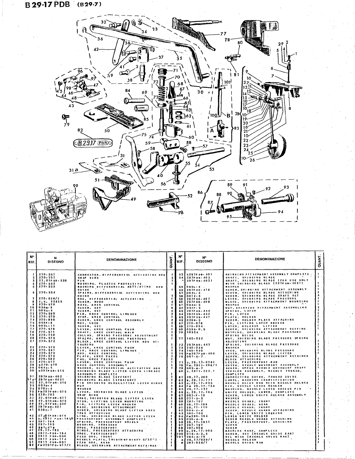
B29·17POB
(829·7)
N•
RIF.
I
2.
3
4
5
7
a
9
I 0
II
I 2
I 3
I 4
I 5
I 6
17
I B
I 9
2.0
2.1
2.2.
2.3
Z4
2.5
2.6
2.7
28
29
30
3 I
I A"
32.
33
34
35
36
37
38
39
40
4 I
H
43
44
45
..
47
••
49
50
51
5%
PM2701PI)•'417/t
N
DISEGNO
470.557
270-701
Z7.0IPos
2.70
..
552.
Z10·
553
210
..
S5<t
no.
55&/.1
2·20
T • S •
270~
570
038M·9
005G•6
2.70•
580
270-579
2:70-998
059P•B
00
SL•
J 1
270
..
578
270
..
57
I
2.70-72.0
270·
57
5
270-572.
270·
57
6
270-SBI
270
..
573
270·
!$7 4
270.582
270.577
G270•570
0 6
~
J::" 5
G297POB•515
2.97PDB•402.
297PDB·..!I021
27.0IPOB·
053P•4
Q70F·
4
PM297PDB·51S
270·
702
2-J.OIPDB-517
27.01~08·
Z7.0ipoa
297PDB•
035c·7
! ?
z~
:;
o:
297
..
194
297-195
I!
':"'•
·!'""'I
29.17-182
2917-PDB-11!4
2.917
PDB-050
2917
P DB
2.917
PDB•051
..
sss
5
518
519
..
szo
401
~: ~ ~a
,,,
.
..
I I 4
CONNECTOR,
SNAP
.,.
•usHING,
.USHING
GUIDE
SPRING,
GUIDE
ROD,
SCREW,
BASE,
SCREW,
SCREW,
PIN,
STOr,
SCREW,
NUT,·
SCREW.
LEVER,
SHAFT.
COLLAR,
SPRI
BLOCk o KNE.E
TACH I NG
L.EVER.
PIN,
ROb,
PLATE,
PAo,
LEVER,
KNEE
WASHER,
SHIRRING
ASSEMBLY
SHI
RAJ
SHIRRING
PIN
NU~
WASHER
LEVER.
Sli
AP
YOKE,
STUD.
PIN.
BASE.
SCR~W,
'IPJ\E
LINK0 SHIRRING
PRESSERFOOT
SPRING,
UUSHING,
SHOE, P RESSERFOQT
HINGE,
SHOE,
fEED
NEEDLE
fEED
BLOCK,
R I N G
• '
1;:11
Dl
FFERENTI
WOOD
KNEE.
SET
SET
KNEE
KNEE
KHEE
LOCK-
SET
KNEE
KNEE
HG,
KNEE
KNEE
KNEE
KNEE
KNEE
KNEE
KNEE
CONTROL
DIFFERENTIAL
NG
SHIRRING
SHIRRING
R I N G
SHIRRtriG
LIFTING
LIFTING
SHIRRING
SHIRRING
ATTACHING'
PRESSERFQOT
PRESSERFOOT
PRESSERFOOT
ODG,
PLATE,
DOG,
SHIRRIN&
Dl
PLASTIC
DIFFERENTIAL
FFERENTI
CONTROL
SPRING
CONTROL
CONTROL
PRESS
DLAPE
COMPLETE
BLAPE
BLADE
THREADED
FRONT
REAR
DENOMINAZIONE
FF'ERENTI
CONTROL
CONTROL
COHTAOL
CONTROL
CONTROL
CONTROL
CONTROL
CONTROL
PRESS
CO~TROL
ASSEMBLY
aLAOELIFTER
LEVER
-ASSEMBLY
AL
PROTECTIVE
AC':'"IiA':'1NG
AL
ACTIVATING
AL
ACTIVATING
LINKAGE
ASSEMBLY
PUSH
MAIN
PRESSURE
PRESSURE
Ll
PUSH
LINkAGE
PU5H
ACTIVATING
LIFTER
(OFFSET)
(STRAIGHT}
BLADE
ILAO!.
LIFTER
LEVER
MOUNTING
ROCKER
ATTACHMENI
Bl,ADE
BLADE
LIFTER
COMPLETE
SHIELD
ATTACHIHG
(WIDTH
Of
ATTACHM.ENTRET~INER
ACTIVATING
ADJUSTMENT
FTER-
ROD
LEVER.LINKAGE
LEVER
Ll
FTEll"
LEVER
LIFTER
LEVER
01
GH'T
5/32"}
.
KN.EE
•
ROD
AT•
ROD
HINGE
ROD
ROD
,.:
z
..
::>
0
N"
RIF.
53
5•4
55
56
57
58
59
60
6 I
62.
63
64
65
66
67
68
69
70
7 I
7l
73
7.
75
7 6
77
76
79
80
6 I
•
63
••
85
• 6
67
68
69
90
~I
9Z
• 3
94
95
96
97
98
99
100
I o I
2.
N"
DISEGNO
G2Q7P.
DB•
297PDB·403
297Pos
..
0 6
SL
• 6
297PDB•418
004L•
6
·ao 1
E.
s
297POB•407
297PD8·40B
0640·5
0
57
p.
5
Z97P
pa
...
Z97Po"a-442
297PDQ•4"1
0
28
B • 5
270·(178
270
..
094.
o~Bn·e·~s
103~A
160·032
Z97PDB
..
2.-40·035
ffiQa
030
PM297PDB·406
00:
I a
D·
7'
G.Z9.t7-0761
PM~
2-9-17"
0~5
..
M•·7
c;.
2.917
..
29,17,
260
e.
29.17
&,.29,17-02.5
PM
29,17-
29,17-132
G,
29,17-
007·-:f•"
I 0
07
I·
o• 5
297·
107
29,
17·-109
~$I
I 7
.. I '·
004·F·4
2.90-I OS
PM2.90·
10.\
039·A~6
2.9.17-192.1
29 7 ..
1 8
'1
2_97..-906
Go
29,17•
ots
..
A
..
~.s
092-A·IO
2.9.17/02.011
2.97·0t5/l
40
4031
444
443
2.08/1
26~.1
..
-171
1;38
104
0
002.
,.:
DENOMINAZIONE
SHIRRING
I
SHAFT,
sHAFT,
WITH
WASHER
SCREW,
SCREW,
SCREW,
LEVER,
B L 0
WASHER
NUT,
SPRING,
PINo
PLATE,
SCREW,
PIN,
LATCH,
SCREW,
BU<;HJNG,
SPRING
NUT,
ADJUSTING
SPRING,
WASHER
STUD,
LEVER,
SCRE'W,
BLOCK
LEVER,
coVER,
SCREW,
TENSION
COMPLETE
CONN
LABEL,
NEE.DLE
PIN,
BUSHING,
KNIFE
SCREW,
WASHER
NEEDLE
NEEDLE
NEEDLE
SCREW,
PIN.
LOWER
SCREW
PLATE,
SCREW
SCREW
MACHINE
SCREW,
OIL
NEEDLE
NE;EDLE
ATTACHMENT
SHIRRING
SHIRR.ING
SHIRRING
SHIRRING
SHIRRING
SHIRRING
SHIRRING
CK
,
SHIRRING
SHIRRING
LATCH
LATCH
HOLDER
HOLDER
LIFTING
RELEASE
SHIRRING
SHIRRING
GUIDE
SH-IRRING
Sill
SHIRRING
SHI
SHI
ATTACHING
PRESSERFOOT
NEEDLE
UPPER
"ASSEMBLY,
E C T I N G G U I
MACHINE
GUIDE
NEEDLE
NEEDLE
HOLDER,
LOWER
GUARD;
GUARD,
GUARD,
NEEDLE
LOWER
KNIFE
NEEDLE
PRESSERFOOT,
. .
BASE,
SET
WICK
(NEEDLE
HOLDER
GUIDE
RAING
RAING
RAING
kNIFE
(NEEDLE
LEVER
HOLDER
BLADE
BLADE
BLADE
ATTACHMENT
BLADE
BLADE
BLADE
ATTACHMENT
AT-TACHMENT
PLf.lE
LATCH
LIFTER
ATTACHMENT
BLADE
BLADE
BLADE
BLADE
ATTACHMENT
MOVEMENT
NF£DLF
DE,
IDENTIFICATION
BAR
WITH
LEVER
LOWER,
KNIFE
FRONT
REAR
FRONT
GUARD
LDeKIHG
GUARD
COMPLETE
GUIDE
BAR
ASSEMBLY
(297PPM·40ZI}
ATTACHING
ROCKER
BLADE
PRESSURE
PRESSURE
·BAR
MOVEMENT
NEEPLE
T H A E
ROCKER
COMPLETE
HoLDER
ATTACH
ATTACHING
CHAINING
GUIDE
(FDA
·ASSEMBLY
ATTACHING
SHAff,
PRESSURE
ASSEMBLING
P"RESSURE
PRESSURE
Ll
FTER
ASSEMBLY
THREAD,
AD
G U I
NEEDLE
ROCKER
ASSEMBLY
INC
BAR)
BAR}
COMPLETE,
US.£
ONLY
SET
MOU~~-~~G
SETTING
SPRING
RETAINER
SliAFT
DE
HOLDER
PIN
z
..
::>.
0
4
I
I
I
2.
1
I
I
z
I
I
I
I
I
I
I
I
I
·I
I
I.
I
I
I
I
I
I
2
I
I
I
I
I
I
I
·I
----------~--
Page 51

~
82
829·17
PDBO
(829·7)
8
N"
RIF.
7
a
g
10
11
12
13
14
t~
16
17
18
19
20
21
22
23
24
Z5
26
2.,7
28
2.9
30
31
lA•
32
33
34
J 5
36
37
38
39
40
41
4~
43
.44
45.
46
47
48
49
50
51
52.
53
"54
N
DISEGNO
270-557
270-701
zJ.otr.oa•
270·
270-553
270-554
270·
r,s.zzx35
2.JQ
03BM•9
005G·6
270·
270·
270
ossr-e
OOSL·If
270·S78
270·571
270-720
270·575
270
no.s76
Z70·581
2.70·573
270•
Z70·582
470·
G270•
064£·5
G297PDB•SIS
297PDB•402.
4!97PDQ•4021
27.otP.oa.,.st~
0530·4
070F•4
Plot
2.70
2.7.01POB·5f7
ZJ
27
2.97PDEJ•40f
DJBc-1""
27.0IPPB~·!ns
G
..
G02.9
297-906
297-179
29
29.17/PDBO·I8.4
29
2.9_17/PDB·II4
29.17/PoB·OSI
PM2701PD
G297Poa.401
Z97P
552
556/1
..
570
580
579
..
998
..
572
574
577
570
..
2.
9 7 P D a·,. 5 I
..
702
•.
OIPDB·S19
..
D1P08•52.0
2917Pna;:,-1.f/t
..
JJ
..
Q02.
..
17·182.
..
17/PoB-050
..
OB•
403
sse
417/f
P
PIN,
P)N
Pl,ATE,
PINSHIRRINGBLADELIFTEA
~.
5.
YOKE.
PIN.
BASE.
LINK.
PRESSERFOOT
MACHINE
PIN.
CONNECTOR,
SNAP
Rl
NG
IN
BUSHING,
BUSHING
SPRING,
G U I 0 E
ROO,
SCREW,
BASE,
SCREW,
SCREW,
STOP,
SCREW,
NUT,
SCREW,
LEVER,
SHAFT,
COI,.LAR,
SPRING,
BLOCK
T.#.CHING
LEVER.
ROD.
PAD,
LEV
KNEE
WASHER.
SHIRRING
ASSEMBLY
SHIRRING
SHIRRING
NUT·
WASHER
L.£V[R~
SNAP
STLiD.
SCREW.
YOKE
SCREW.
COLLAR.
SHOE. P HESSER
FEED
N~EDL
FEED
BLOCK.
SHIRRING
SHAFT.
PLASTIC
Dl
DIFfERENTIAL
Dl
FFERENTI
WOOD
KNEE
SET
SET
KNEE
kNEE
KNEE
LOCK
SET
KNEE
KNEE
SPRING
KNEE
•
KH~E
KNEE
kNEE
0
KNEE
kNEE
kNEE
E R • K N E E C 0
CONTROL
DIFFERENTIAL
BLADE
COMPLETE
Bt.:At;IE
BI.ADE
SHIRRING
R I H G
SHIRRING
LIFTING
LIFTING
SHIRRING
SHIRRING
ATTACHING
SHIRRING
BASE.
PRES.SEREODT
PRES5ERFODT
PRESSERFOOT
PDG.
e P
L"AT
DOG·.
SHIRRIN~
ATT
SHIRRING
DENOMINAZIONE
Dl
FFERENTI
PROTECT!
Ff'EAENTI
CONTROL
CONTROL
CONTROL
I'RE$:i
FRONT
REAR
AL
CONTROL
CONTROl.
CONTROL
CONTROL
CONTROL
PRESSURE
CONTR.OL
CONTROL
CONTRO~
PRESS
NT
ASSEMBLY
LIFTER
(OFFSET)
(STRAIGHT)
BLADE
LEVER
LEVER
ATTACHMENT
BLADE
ASSEMBLY
COMPLETE
FOOT
£.
(WIDTH
ACHM
AL
ACTIVATING
Ll
LINKAGE
R 0 L P U S·H
BlcAPE
!SLADE
SHOE
ATTACHMENT
EN T AS
BLADE
AL
ACTIVATING
VE
A.C":"l"iA'!ING
ACTIVATING
NIC
AGE
ASSEMBLY
PUSH
MAIN
ADJUSTMENT
PRESSURE
Ll
FTER
ROO
PUSH
ACTIVATING
LE"/ER
LINKAGE
LEVER
LIFTER
LIFTER
MOUNTING
ROCKER
ATTACHING
ATTACHING
0 F D I
LEVER
LIFTER
LIFTER
LEVER
COMPLET~:
ATTACHING
G·HT
R·ETAINER
SE.MBL Y COMPLETE
KNEE
I
3/3"2.
HINGE
AT.;
ROO
ROD
RDP
••)
ROD
,_;
~
5
I
I
4
I
•
2
2
I
2
2
I
I
I
I
I
N"
RIF.
2.97P
065L•
S5
2.97PDB•418
56
004L·6
57
00
1
58
2.97P
59
297PDB•408
60
0640·
6 I
057P•5
62
297l"DB•444
63
2.97P
64
297PPB•441
65
0280•
66
270-078
67
270-094
68
69
039R·8.5
70
I o 3
7 I
I
60·
2.97PDB•443
72
240-035
73
160·030
74
PM2971'
75
76
00
I·
PM297/rooo-
77
PM2.97/PtJP04131
00 I ..
78
G.2.9.17•0761
79
PN.2.917·208/I
80
29·17·280
8 I
005·M•7
8 2
G.
2917.•
83
G.
29•
8 4
092·A·IO
8 5
016•A•2.5
86
PM•29·17•IJ8
87
29.17·132
88
a,
29.17·
89
G•2.7.26PDB0937
90
0 I 7
..
9 I
PM~602·141/I
92
TS
93
PM.27.26Poool42~
•
•I
95
0 7 f •
297-107
96
007·P·
97
2 9
..
98
99
29·17
I
00
039-A•G
004-F
10
I
P ......
290-105
103
1 o
21
G.2.9.17-104
I o 4
A
29.
2.97-025/1
•
N"
DISEGNO
pa
.. · 4031
6
E•
6·
DB•
407
5
D8•
442.
5
2"
03
2.
DB•
P·
7
E-•
7
262/1
17-02.5
t
..
7
20X30
D•
5
IO
17
..
1 I 0
..
109
..
4
zsa~·t
o 4
17·020/1
..:
DENOMINAZIONE
z
...
8
SHAfT.
SHIRRING
WI
T H S
HI
CREW
E.
WI_
L £
SHIRRING
LATC'"H
LIFTING
SHIRRING
ROLL
SCREWS,
LOWER
R R I N G
SHIRRING
SHIRRING
SHI
SHIRRING
SHIRRING
LATCH
HOLCER
H.OLOER
RELEASE
SHIRRING
GUIDE
SHIRRING
SHIRRING
SHIRRING
SHIRRING
ATTACUI
CORD
CORD
GUIDE
PRESSERFOOT
NEEDLC
UPPER
ASSEMBLY.
GUIDE
C K
IDENTIFICATION
SET
BAND
GUARD.
LOWER
GUARD.
GUARD.
NEEDLE
(LO.WER
ATTACHG.
KNI
KNIFE
HOLDER
GUIDE
WASHER
SCREW,
SCREW.
SCREW,
LEVER.
BLOCk.
WASHER
NUT.
SPRING.
PIN.
Pl.Al
SCRCW.
PIN,
LATCH.
SCREW.
BUSHING.
SPRING
NUT.
ADJUSTING
SPRING,
WASHER
STUD.
413
LEVER,
SCREW.
BLOCK
GUIUE,
GUIDE,
SCREW.
LEVER,
COVER,
CONNECTION
SCREW.
TENSION
NEEDLE
0 I l
5
PIN,NE:E:.:.E
PUSHING,
LABEL,
BAND
SCREW,
BASE,
WOOD
TAB
OISC0 BINDING
WASHER
NEEDLE
SCREW.
NEEDLE
NE"'EDLE
SCREW,
SCREW,
GUARD
LOWER
PIN.
LOWER
NEEDLE
NEE.DLE
406
171
RRI
SHIRRING
GUIDii.,
LEVER
NEEQLE
SUPPORT,
BAND
ROLL
F~
IIOLDER
KNIFE
HOLDER.
BLADf
!I
l
II
DE
ATTACHMENT
PLADE
HG
BLADE
BLADE
ATTACHMENT
ATTACHMENT
PLATE
LATCH
Ll
ATTACHMENT
SLAPE
IILADE
BLADE
BLADE
ATTACHMENT
NG
(5/64'").
(
1/8"')
ATTACHING
MO'{EMt~1
NEEDLE
BAR
LEVER
ROLL
SUPPORT
BAND
ROLL
FRONT
KNIFE
FRONT
REAR.
GUARD
KNIFE
BAR
ROCKER
FTER
BLADE
PRESSURE
_BAR"
THREAD
MOVEMENT
NEEDLE
AND
ROCkER
COMPLETE
ROLL
SUPPORT,
HOLDER
LOCKING
COMPLETE
(FOR
• 2.9..,. •
ATTACHI-NG
SHAF·T
PRESSURE""
ATTACHING
PRESSURE
PRESSURE.
PRESSURE
Ll
FTER
ASSEMGLY
NEEDLE
ROCKER
OF
SUPPORT
SUPPORT
ATTACHING
HOLOER)
USE
Po
!II
• 4 9 2 0
ASSEMBLY
SET
MOUNTING
ASSEMBLING
SETTING
SPRING
RETAINER
GUIDE
SHAFT
THRE·AD
HOLDt:R
PIN
MACHINE
BASE
COMPLETE
ASSEMBLY
-
NEEDLE
ONLY
A.'I"T.TO
-----.-------------
Page 52

(829·7)
I
I
I
I
I
I
I~
9
,.
N"
RIF.
I
2
3
~
5
U.17/Poi.'ll
2S
u,
0.
u.
H.IH•
•
N"
DISEGNO
17/PDI.
17/i'oo.
29.
174-1
174•"11~
112·
~
0~01
oOl
II
NIEEDI.E
FEED
FEED
f
PIESSERFOOT,
'"'~·
PLATE,
PLAtt.
DOG,
fi'ONT
DOG,
II·£ A
P•EStEIIFIDT
PltESSJitFOOT",
.
DENOMINAIIONE
-·
WIDTH
It
COMPLETE
or.
CHA.IN
•tGHT
tH.G
12/32.
l
I
I
I i
I
I
I
N•
RIF.
10
II
12
'2t.17.C-t82
7
U7•
•
217·
287·
217•
217-IOtli
..
N"
DISEGNO
117
....
It
5
1·71
~
.....
JC
lillW
SPJl
IUIHIIII,
p I
H'
·sew
P
[ 0
INc;
PJltiSERFIIT
IE
•
DEI\IOMIN.UIONE
ll t s.S.Eflf' 0 If
THREADED
S
HIE
ATTACH·I
HG
...:
~
8
I.
'I
I
I
..
I
Page 53

B29·7W
(B29·7)
N'
RIF.
2
3
•
7
•
9
I 0
II
DISEGNO
a
2..70/w~
I
G~297/YI·3220
PN~297/W•P760
270/W•J220
270/w-~2~0
5
570/1•3240
6
270/w
G,.290/W•2IOO
004
..
L·
270/W•
o6s-c-6
16
\.,_
__
N"
3320
..
JZSO
5
3550
_
v
17
SOLENOID • PLUNGER
PJtESSEWFOOT
PRES5ERFOOT
I,.
EYER,
PRESSER
WASHER
6PR.ING,
SCREW,
.WORk r
WASHER
SCREW,
WASHER
Kill
KNIFE
LATE,
".COUN.TlHG
J
DENOMINAZIONE
ASS
LEVEJt
l.IFT£R
LIFTER
LEVER
FOOT
H.,.LD I fiG
FE
RETURN
RETURN
COMPLETE
.RACKET·
SPA
EMILY
•••
IAR·
lNG
ATTAcHiNG
COMPLETE
COMPl.~TE•
WITH
Kt(IFE
..:
z
RIF.
:::>
"'
0
I
I
I
I
I
I
I 1 a
I
3
3 21
2
N"
12
I
••
I 5
I 6
17
19
~0
3
.
DISEGNO
270/w.JZJO
217/w
z7o/w.
D3t
..
o
270/w
PM210/W•
o.
270/w•
$48.
G,
270/w.
547
..
..
..
N
z47D
63iO
o4/a
6500
6400
3330
33-40
Ill
AC
KI;T,
COVER,
FEED
STOP,
....
SCJtEW,
WOIIIlt
ILOCit,
GUIDE
GUIDE I LOCK
VOLTAGE
WIllE
KNEE.
Wilt£
TRANSFOIINEil
HANGEII,
SWITCH
HANC:ER,
DENOMINAZIONE
50L["etD
MI:CHANI.N
~
PLATE
PlATE
OIFFEII[NTIAL
AND
STtr,
SIMP
ASSEMtLY
oou•LE
llfOU.NTINc;.
(AVOip
STOP
ASSENILY
L [
COMPL~T~
OIL
ATTACHING
f[tD
COMPLETE
sr
L
~"'·s
LitY£"
CINPI.r:tl:
..:
z
:::>
"'
0
I
I
."
~
I
I
J
I
I
10
I
5
----~~~
----~----~-
~~--~
Page 54

B29·7PDB
(
829·7)
N"
RIF.
I
2
3
4
5
1
•
9
I 0
II
t2
13
I 4
I 5
16
17
18
I 9
20
2 I
.,
23
24
25
26
27
,.
29
10
3 I
.11 A
3?.
33
,.
35
36
17
38
39
40
4 I
DISEGNO
2.70·557
270·701
z7.otPDQ-
270·552
270
..
553
270
..
55o1p
270·
556/1
T.s.ZZXJS
2
10·
-5
]0
03RM·9
Od
SG
..
6
270-580
210·
579
210· 9 96
059P•8
005loll
270·
578
270·
571
?70·720
270·575
2.
70-
57
270
..
576
2]0
..
581
?70-573
270·
574
270
..
582
270,.577
G270~
570
p
011
r
..
r.
oz97Pnn
297PDB•
297PD8•
27
..
01PtltJ•518
0
53 0 ..
"
070F•
4
PM297PDII•
270-102
27,
OIPPII•
2.7
..
DtPnll·
27.
01POII•
297P00-401
OJBc·7
N"
:l
..
s1s
402
402-1
ssa
515
517
519
52.0
J
CONNECTOR
S
HAP
R I N G
PIN
BUSHING,
BUSHING
GIJ I D £
SPRING.
GU I
0£
ROD.
DIFFERENTIAL
SCREW,
8A5[,
SCR£W,
SCREW,
PIN,
KNEE
STOP,
SCREW,
NUT,
LOCK
StREW,
~EVER,
SHAFT,
COLLAR,
SPRING,
~LOCK,
LEVER,
PIN,
KNEE
ROD,
KNEE
PLATE,
PAD,
KNEE
LEVER,
KNEE
CONTROL
WA3fi£R,
SHIRRING
ASSEMBLY
sHIRRING
SHIRRING
PIN
SHIRRING
NUT
WAStiER
LEV£R,
SNAP
RING
YOkE,
SHIRRING
STUD,
LIFTING
PIN,
LIFTING
!AS£.
SHIRRING
SC~EW,
'rOKE
ATTACtliNG
DENOMINAZIONE
DIFF(R~NTIAL
PLASTIC
Dl
FFE'RENTIAL
DIFFERENTIAL
WOOD
KNCF.
CONTROL
Stt
SET
CONTROl:
KN~E
CONTROL
KN££
CONTROL
SET
KNEE
CONTROL
KNEE
CONTROL
SPRING
KNtE
CONTROL
KNEE
CONTROl.
KNEE
CONTROL
CONTAO'CONTROL
kNEE
PRESS
PRESS
KNEE
CONTROL
A$,EMDLY
nlfFERENTIAL
BLADE
COMPL~TE
BLADE
BLAPE'(STRAIGHT)
I!ILAI)E
SHIRRING
LEVE'l
SHjRRING
PROTECTIVE
ACTIVATING
L I
PRESSURE
LIFTER
PUSH
LIN·KAGE
PUSH
LIFTER
(OFFS~T)
LIFTER
ltl.ADE
BLADE
llYER
MOUNTING
ROCKER
ATTACHMENT
eLAPE
ACTIVATING
AC'!I·iATI"NG
ACTIVATING
NKAG£
ASSEMBLY
PUSH
MAIN
ADJUSTMENT
PRESSURE
ROD
ACTIVATING
L~VER
LEVER
LIFTER
t.IFTER
iiFTER
ROD
ROD
ATTACHING
ROD
LINKAGE
HINGE
LEVER
KNEE
ROO
...:
z
:::>
"'
0
3
.I
I
4
9
t
2
I
2
t
I
I
I
I
I
I
I
I
I
I
I
I
I
I
N"
RIF.
4t
I
43
44
I
45
46
47
48
49
I
50
I
51
5t
I
53
54
55
H
57
58
59
80
6 1
6t
63
64
85
66
67
~8
69
10
71
72
13
74
75
16
11
18
79
80
N
DISEGNO
2.7.0Jroe.·
i 9
297•
2.97·194
t91·
297·
297/PDI•
2.97/Ppa·
297/PoB•
t91·
297/Poe
297/PDI!i•l141
PM 2 7 0 I
G,·297/POI!i•
297/PDI•
297/PDI!i•
0 ti
297/Poa
004•
0 0
a7/PD8•
297/Poa
064•0•5.
0
57·
2i71PDI!i•
297/PDII•442.
2..9l/PDB•
0
:~
270·078
!!70·
039•R
1032
160·
297/PBD·
240·035.
t
so
PM,
0
01.
••
Z97•
516
~:·I~~~
•.
I 8
179
182
906
184
050
051
195
..
tl4
/P
D 4 I 7
401
403_
4t;l31
5·
L • G
..
416
L•
6
I·
E"
G
407
..
40B
p.
t5
444
44f
•••
5
094"
..
a.~
A
Oat
443
..
030
297/PDt'l•
o
...
7
2.97·171
187
DENOMINAZIONE
tiNK.
SIIIRRING
PRESSERFODT,
1/1
PLATE,
PRESSERFOOT,
PIN,
PRE5SERfOOT
SPRING,
HINGE,
PRESSERfOOT
SC
ll
E
Yt
$HOE,
PRES~ERFOOT
FEED
DOG,
FEED
DOG,
=~==~=G;L!::E:=~~TH
NEEDLE
PLATE
BLOCk,
SHIRR
lNG
SHAF~.·
SHAFT,
297POB•
WASHER
SCREW,
SCREW,
SC
R
[.W,
LEVER,
BLOCK,
WASHER
HUT,
SHIRRING
SPR
lNG,
PIN,
LATCH
PLATE,
'CREW,
PIN,
LIFTING
LATCH,
SCR~W,
IIUSIIING,
NUT,
SHIRRING
Ao.JUSTING
SPRinG,
WASHER
STUD,
LEVER,
SCREW,
I L
DC
PLATE,
5CREW,
TACHIH6
S,HIRRIHG
SHIRRING
SHIRRING
402.1)
SHIRRING
SHIRRING
SHIRRING
5ltiRRING
SHIRRING
HOLDER
IIO~DER
RELEASE
sHIRRING
SHIRRING
SHIRRING
SHIRRING
K
MACHINE
fRESSERfOOT
/1
406
BLA.DE
CDMPLFTE
P~E5SERFOOT
FRONT
REAR
(WIDTH
ATT.ACHMENT
LATCH
LATCII
SHIRRINGI!I:LADEP·RESSURESPRING
SHIRRING
LIFTER
CHAINING
SHOE
cHAINING
ATTACHING
Of
Of
ATTACHMENT
ASSEJULY,
BLADE
BLADE
ATTACHMENT
BLADE
ILADE
ILADE
ATTACHMENT
ATTACHMENT
PLATE
ATTACIIIHG
ROCKI:R
lifTER
ATTACHMENT
I!I:LADE
PRESSURE
BlADE
BLADE
PRESSURE
BLADE
ATTACHMENT
IDENTIFICATION
CHAIH rLAT~
BIGHT
BIGHT
RETAINER
{USED
·ASSEMILY
.ATTACHING
SHAFT
PRESSURE
MOUNTING
ASSEMILV
SETTING
PRESSURE
LIF~ER
RETAINER
LEVER
PLATE
~/32'')
15/64'')
COMPLETE
WITH
SET
SI'RIHG
AT~
1
·.J
I
I
1
I
I
I
I
I
1.
I
I
I
I
I
I
I
I
2
4
I
I
r
z
I
I
I
t
I
.I
I
·I
I
.I
I
I
I
-·--------------
Page 55
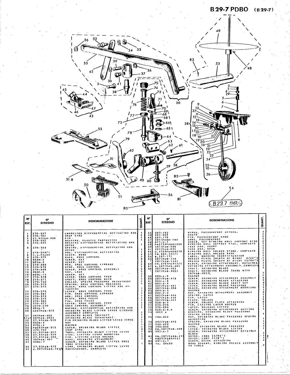
B29-7PDBO
(629·7)
/
/
/
49
/
/
/
I
\
'
'
'
'
I
\
.....
/
\
\
\
I
30
28
.....
'
'
N"
RIF.
l
z
3
4
5
7
8
~
I 0
II
I
2.
13
14
I 5
H
17
18
• 9
20
2 I
22
23
24
25
26
?7
28
29
30
31
Ill
A
32
33
34
35
H
37
..
••
40
4 I
42
43
DISEGNO
270-557
2,70·
70
t
2.1.
otPoth
270·
552.
270-553
270·554
21Q·
:556/1
T
..
,.zzxJS
2.
70·
570
03
SM
..
9
QO
5G•
6
270-.580
2.70.579
2.70
..
990
0 5
9P
..
8
OOSL•
I I·
270·
57
8
2 7 o.
57
1
270.720
270·
575
270-572.
•270-
576
270·
581
270-573
2.70
..
574
270·
582
2.70-577
G2.70·,570
064~-5
G2.97PD8•
Z97PDII'"
297Poa-40ZI
27.01PDB•518
0530
..
4
D70r•A
PM297PDB•
270-702
Z 7 •. 0 1 P D
27,01PDII•
Z7,01POII•
297PDII•
o38c-7
Z7,01PDB•516
G.
2.97/POIIO·
N'
t102
II•
401'
sse
515
515
51 7
519
~;!.0
'
181/
DENOMINAZIONE
~ONNECTOR
SNAP
PIN
BUSHING,
BUSHING
GUIDE
SPRING,
GUIO~
R Q
D.,
SCREW,
SASE,
ScREW,
SCREW,
P'l
N..
STOP,
SCREW,
NUT.
SCREW,
LEVEe,
SHAFT,
COLLAR,
SPRIH.G.
BLOCK.
T
~CHING
LEVER,
PIN.
ROD,
PLATE,
PAD,
LEVER,
KNEE
WASHER,
SHIRRING
ASSEMBLY
SIIIRRING
SHIRRING
PIN
NUT
WASHER
LEVtR,
5
NAP
~UKE,
STUD,
P·IH,
BASE,
SCREW,
VOKE
LINK,
PRESSERFOOTo
.DIFFERENTIAL
RING
•
PLASTIC
DIFFERENTIAL
OIFF•J;R~NTIAL
D I F F E R E
NT
I A L
WOOD
KNEE
CONTROL
SET
SET
K
l{
E E C 0
NT
CONTROL
KNEE
CONTROL
SET
KNEE
CONTROL
KNEE
CONTROL
~PRINa
KNEE
KNEE
CONTROL
KNEE
CONTROL
CONTROL
CONTROL.
KNEE
PRESS
PRESS
KNEE
CONTROL
DIFFERENTIAL
SLADE
CDMPLFTE
BLADE
.BLADE
IILADE
SHIRRING
SHI~RING
R 0 L L I N K
PRESSURE
CONTROL
ASSEMSLV
LIFTER
(OFFSET)
(STRAIGHT)
I!LAD~
LEVER
LEV~R
ATTAcHMENT"
BLADE
COMPLETE
KNEE
LOCK
KNEE
KNEE
KNEE
cONTROL
SHIRRING
R I N G . .
SHIRRING
LIFTING
LIFTING
SHIRRING
ATTACHJNG
SHIRRING
ACTIVATING
PR~TECTIVE
ACTIYIATING
AC.TIVATI.NG
AcT
I V A 1 I N G
AGE
ASSEMBLY
PUSH
M~IN
PiRESSUJiE
LIFTER
PUSH
LI·HKAGE
PUSH
ACTIVATING
LEVER
LIFTER"L£\IER
llf..ADE
LIFTI:R
LIFT~R
MOUN.TING
ROCKER.
ILADE
LIFTER
LIFTER
.
.
ADJUSTMENT
ROD
LINKAGE
L~VER
KNEE
LEVER
R.OD
.
AT•
ROD
IIINGE
ROD
ROD
DISC
D/32.'')
,.:
z
oC
5
.I
I
I
I
I
2
I
I
I
I
I
I
I
I
I
I
I
I
~
2
4
I
I
I
2
I
I
·I
2
I
I
I
N'
RIF.
44
45
4 6
47
40
49
so
51
sz
53
54
55
56
57
s•
59
60
6 I
62
63
64
65
66
67
60
69
70
7 I
72
73
74
I
1
75
I
I
76
I
I·
77
78
I
79
3
ao
I
I
8 I
I
I
82
83
N'
DISEGNO
~
9
7•
I 8
2.
2.97·
906
297•
1 H
297/..Poeo-
0 I 7 • E
•.
7
PM272.6PDBOI425
297/P
Dl!l·
297/Por~
Go
2726PDB09375
PM,602·141/I
11. 2 9 7 • I 7 I
2.97/PPB•
297/PDO•
f'M,
2701f'0417/1
Go
~97/PDB•
297/PDB•
297/PPB•
065·L·6
297/PoB·
004•L
..
6
0 0
1•
E • 6
297/P'Q a-407
297/PDII·
064·0•
5
0
57
..
p.
5"
297./PDII·
297/PDB•
.297/PDB•.441
0 2
8·
I!
•.
::;
270·
076.
PO·
0 9 4
o39·n
..
e.s
103
2 "
160o032
297/PDB•
240-035
160•
.030
PM,
2.97/PDil•
0 0 j •.D,... 7
PM.2.97/POII0•41
PM297PDft04131
0 0 I •
E,
7
TS,
20X30
..
·
18.4
050
OSI
tl4
1141
•103
4031
41
408
444
442
443
401
a
406
HINGE,
SCREW
PIN,
PRESSERFOOT
SHOE.
PRESSERFOOT
SCREW,
BINDING
FEED
DOG,
FEED
DOGO
BINDING
BINDING
LABEOL,
NEEDLE
NEEDLE
IILOCK,
"$HIRRING
SHAFT,
SHAFT,
297PDB~
WASHE"R
SCREW,
SCREW,
SCREW,
LEVER,
IILGCK,
WASHER
NUT,
SHIRRING
SPRING,
P I N , L
PLATE,
SCREW,
PIN,
LIFTING
L~TCH,
SCREW,
BUSHING,
SPRING
NUT,
SHIRR
ADJUSTING
SPRING,
WASHER
STUD,
lEVER;
SCREW.
BLOCK
GUIDE.
GUIDE,
5 C R E W 1 G V J
WOOD
SCREWS,
TO
TABLE
DENOMINAZIONE
PRESSERFOOT
SET
BINDING
ROLL
FRONT
REAR
ROLL
ROLL
MACHINE
PLATE
PLATE
SHIRRING
ATTACHMENT
StliRRING
SHIRRING
402.11
1
SHIRRING
SHIRRING
SHIRRING
SHIRRING
SHIRRING
LATCH
A"T
C H
HOLUER
HOLDER
RELEASE
SHIRRING
SHIRRING
GUIDE
lNG
SHIRRING
SHIRRIIiG
SHIRRING
SHIRRING
CORD
(5/64"1
COR£1
(1/U"J
DE
..
sHOE
SUPPORT
HOLDER
HOLDER
IDENTIFICATION
(WI.DTH
(WIDTH
ATTACHMENT,
IILADE
BlADE
ATTACHMENT
BLADE
BLADE
BL~DE
ATTACHMENT
ATTACHMENT
PLAT£
LATCH
LrFTER
ATTACHMENT
II
LADE
IILADE
BLADE
"BLADE
ATTACHMENT
AT
T A
c"H
BINDING
ATTCHG.
ROLL
DISC,
STANO,
IIASE.
OF
OF
ASSEMBLY,
ATTACHING
ROCKER
IILADE
PRESSURE
PRESSURE
I N G
SUPPORT
!tGHT
I!IIG~T
(USED
ATTACHING
SHAFT
PRESSURE
AS~EMaLY
PRESSURE
PR£S$URE
LIFTER
HOLDER·
COMPLETE
COMPLETE
15/64")
RETAINER
COMPLETE
WITH
ASSEMBLY
SET
MOUHTING"
SETTING
SPRING
hETAINER
ASSEMBLY
~~--------L-----------------~--~~~~~~----~--------------------~~
-----
____
.:____
I
1_.
Page 56
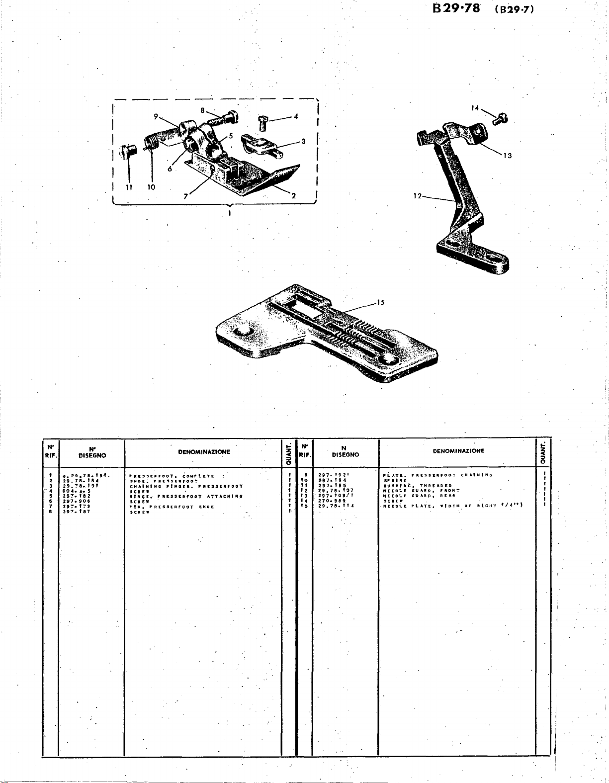
B29·78
(B29·7)
--·--
----
-
--.,
I I
I
I
I
I
I I
I
'f
11
I
10
I
I
I
Rlf.
.•
N"
'
~
4
5
•
7
•
~
DISEGNO
G.
t9.7a.
U.70-IA4
2
9.
'!e.
00
.C.
A•
291.
fa
297-900
297-179
29':'. f 87
...
t 9 t
5
2
tat.
PJt£5SEafOOl,
PR£SSERFOO':'
SHO!.
~
CHAINING
SCR£W
M l N G E
••
SCJI
EJ'
PIN,
PRESSER
SCREW
DENOMINAZIONE
CoMPLtT£
f
I,.
G
f;".
rttESSERFODT
FOOT
P
RESSEIHOOT
A':'TAC~ING
SHOE
..:
~
8
I 9
I
I
I
'
'
I
I· .
...
RIF.
lo
'2
"
I 3
'4
5
I
DISEGNO
297~
H7.194
297-195
Z9.7e
297·
270-989
29.78·''"
N
t9t'
..
toa/r
to7
pLAT£.
$P
A I H G
BUSHfNG.
N££DLE
P4EEOLE
SCREW
NEEDlE
DENOMINAZIONE
PRESSERFOOT
"!'H.R~ADED
GUARD, f RON";
GUARp,
REAR
PLATE,
WIDTH
CHAINING
Of
II
f.
GH"!'
..:
~
8
·t
/4")
Page 57

(829·7>
,--
/
I
I
I
I
r-
1 .
•)~
I .
I
,6
---
N"
RIF.
I
2
l
4
5
6
7
e
9
to
.,,
'2
13
DISEGNO
Ge2-97/R.Ietr
297. f :'
g
'1,.97/R•
fe'4f
297/R-071
oo4•P•"·s·
297·.
182
297·
906
297~187
297·
19
21
297·
194
297.195
20.
30
TS
Z97.1141/l
18
19
12
~20
,.:
N"
PRESSERFODT,
P
I.N;
·I
SHOE,
GUID£,. P RESSERFOOT
SCREW
HINGE,
5
CREW
SCREW
Pt.
ATE,
SPRING,
BUSHING,
TH R E·AD
NEEDLE
P
RESSERFDO"':'
P R E S S E R F 0 o
P
RESSERFOOT
P
RESSERFODT
P
RESSERFOOT
THREAI)ED
STAND
PLATE
DENOMINAZIONE
COMPLETE
SHD
E
T·
CHAINING
ASSENILY
WIPTH.OF
•
SE:l'!"ING
liGHT
,~]=~~.
z
,.
"'
0
N"
RIF.
'.
'
I 5
I
'
I 6
17
I 8
'
I
I
9
'
I
lO
I
21
22
'
I
23
24
'
25
2
I
N
DISEGNO
PW.
297/R•·Z67
2!7/R•
267
057·
,h• 3
.oo
1.
c··
s.
250/R••9373
143
723
s
G•
605·144
0 I I 4 I
oot~G.f2
605·
605·
605·937
.6o~.9eo
GUIDE
GUIDE
NUT
SCREW
TAPE
RO
0 I
I
J.S
SCREW
ROD,
AXLE,
IRA"CK
SCREW,
•
REINFORCING
REEL
TAPE
E,
TAPE
T
E
DENOMINAZIONE
REINFORCING
STAND,
REEl
A
EEL
p E
REEL
...
REEl
TAPE
TAP' E REEL
STAND,
STAND,
A
EEl
ST:ftND
•TAP
E,
":'APE
COMPLETE
IJP
MAIN
SUPPORT
AXLE
SET
COMPLETE
PER
,.:
z
"'
8
I
I
'
I
I
'
I
I
'
2
I
•
..
.
l
'
....
Page 58
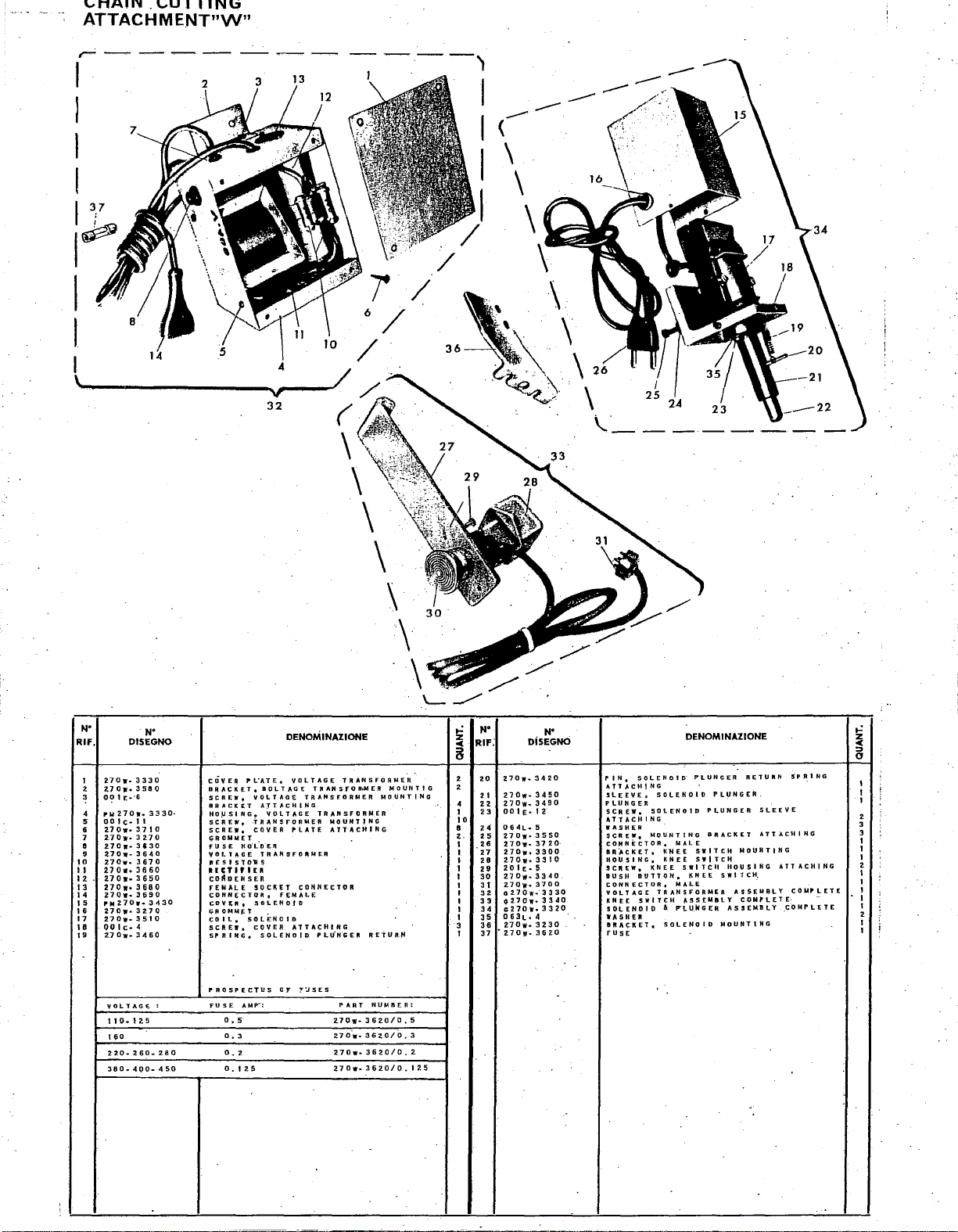
CHAIN.
CUTTING
ATTACHMENT"W"
13
3
I
't
(--
I
\
--
--
I
\
I
\
/
/
/
~'.
\
\
~··\
"~~·\"
\.'_
N"
RIF,
1
2
3
·.
•
~
6
7
8
9
10
II
"
13
14
I 5
16
17
18
19
DISEGNO
2.7Dw-
Z-70w.
0'?
1 [
..
rwz7ow
00
I c-1 I
270w.3710
27Dw-
270w-
~70w-
Z70w-l670
now.
now-3650
270w-.
~70w
..
PMZ70w
270W•
270w-
QO I C•
Z7Dw-
YOLTAG~t
t 1 o
..
160
2:20-
380.
N'
3330
3580
·6
..
3270
3•3o
3640
3660
3680
3690
..
3270
~510
4
;:1460
1 z 5
2.60-
4QO-
33~0·
J"30
:
2.80
450
PL.ATE,
cOvER
BRACKET,
SCREW,
BRACKET
HO.USING,
SCREW,
SCREW,
GROMMET
HO"l.OER
FU
$ E
VOLTAGE
IllES I STO"RS
OICTHIU
COdDENSER
fEMALE
COHH~CTOR,
CDY~R,
Gt~OMM~T
SOLi:::NOID
co
ll.
5
CREW,
SP R IN
10
•
PROSPECTUS
AMP-:
FU
5 E
0.
5
0.
3
o.
2
o. I 25
DENOMINAZIONE
VOLTAGE
IOLTAGE
VOLTAGE
A]T,I.CHING
VOLTAGE
:TRANSFORMER
COVER
PLATE
TRANSFO"NER
socKET
f~NALE
SOLENOID
ATTACHING
COVER
SOLENOID
OF
TRANSFORMER
TRAHSFOR•MER
TRANSFORMER
TRANSFORMER
MOUNTING
ATTACHING
CONNECTOR
PLU'N"GER
~:IS
E S
PART
z7ow-
2.70-w27Dwz7ow
MOUNTING
REi"UR.~
NUMBER:
36zo/o.
3620/0.3
362.0/0.
..
3620/0.12.5
MOUNTIG
5
2.
..:
z
""
8
•
2
•
1
to
8
z.
I
I
1
I
1
1
1
1
1
1
3
1
N'
RIF:
20
>I
22
23
z4
25
26
27
28
29
30
31
32
33
34
35
36
37
DiSEGNCi
270w
..
3420
2.7Dw·
3450
270w
..
3490
00 1 E•
I 2
064t
..
5
27Dw-
3550
27Dw-
37
270w.
~300
270w
..
3310
20
IE
..
5
27Dw-
3340
Z70w-
3700
o27Qw
..
G27ow·
ez7ow.
063t.
4
270w-
3230
•z.7Dw-3G2.0
N'
20·
·3330
3340
3:320
SOLENOID
I'
IN,
ATT.-,cttl
SLEEVE,
PLUNGER
SCREW,
ATTACHING
WASHER
$CAE~,
CONNECTOR,
flft)CKET,
HOU!il
NG,
SCREW,
BUSH
BUTTON•
CONNECTOR,
VOLTAGE
5
WITCH
KNEE
SOLENOID
WASHER
BRAc;:KET,
rusE
NG
SOLENOID
SOLENOID
MOUNTING
MALE
k'N
E E
KNEE
s
KNEE
MALE
TRANSFORMER
'-SSEMBLY
A
P"l~kGER
SOLENOID
DENOMINAZIONE
P'LUNGER
SWITCH
SWITCH
WIT C II
KNEE
PLUNGER.
PLUNGER
BRACkET
!lOUSING
SWITCH,
ASSEMBLY
MOUNT
RETURN
MOUNTING
ASSEMBLY
COMPLETE·
lNG
5P
SLEEVE
ATTACHING
ATTACHING
COMPLETE
COMPLETE
~I
,.:
z
:::>
""
0
N G
1
1
1
•
3
3
I
1
1
z
1
1
1
I
1
2
1
1
 Loading...