

Page 1

FI
( 1 .
~-'
J
I
111
II
:
II
I
SPARE
PARTS
class
and
subclasses
B
CATALO
27·77
GUE
Page 2

-
MACHINE
II
-TECHNICAL
I I I -
TECHNICAL
-
a -
Poaitioning
b - Assembly
c -
lubrication
d-
Assembling
e -
Positioning
f -
Setting
!I
- Needle
I N T R 0 0 U C T I 0 N
IDENTIFICAtiON
DATA
BY
SPECIFICATIONS
I N S T R U C T I 0 N S
INSTALLATION
of
of
of
Thread
Head
TransMission
and Ad'
of
Presaerfoot
front
Cover
Take-up
l N 0 E X
MACHINE
AND
TIMING
juatlng
Plate
Adjustment
CLASS
Sewing
Arm
Parts
Page 5
II
II
Page
II
II
II
II
II
I~
II
I~
II
I~
5
5
9
9
9
9
9
II
- U S E
a-
Threading
b - Changing
c -
Setting
d -
Setting
e -
Stitch
f -
Adjustment
g-
Problems
II I
-MAINTENANCE
a - Every
b - Every
c - Every
-
Sharpening
d
e
- Changing
-
Introduction
a -
Procedure
b -
-
"
Parts
All
a -
Needles
b -
Ill
- T
t~e
the
of
Length
due
Day
Week
Three
of
SPARE
HOW
TO
TO
HOW
A B L E
Needle
Presserfoot
Tensioning
Adjustment
of
Seam
Width
to
improper
Months
the
Knives
Main
Shaft
PARTS
USE
THIS
ORDER
s
Discs
handling
(if
required)
CATALOG
CATALOG
of
machine
II
15
II
15
II
17
II
17
II
17
II
17
II
17
II
18
II
19
II
19
II
19
II
19
II
19
II
19
II
23
II
23
II
23
II
23
II
23
II
23
II
25
OF
IV -NUMERICAL
INDEX
PARTS
II
72
Page 3

INTRODUCTION
3
Page 4

-
MAC:
III
Nt:
llli':Nl'll'lf.A'I'I
ON
a} lDENTlFlCATlON
l-Each
2-
3 - The
-
Class
-Serial
The
Class
held
Ser
needle
Machine
by
i a I Number
plate.
or
Sub-Class
Number
or
two
NUMBERS
is
identified
Sub-Class
screws
Number
on
is
punched
Number
the
by;
base
Is
on
indicated
of
the
the
machine.
machine
on
base
the
name-plate,
next
to
the
The
machines
the
following
I-
Straight
2 -
Greater
3-
Differential
ij-
Push-Button
5 -
Stitch-Length
6-
Differential
7-
Width
8 -
Speed:
and
9-
iO -Motor:
II
-Outer
12 -Weight:
manufacture.
Lubrication:
and
manufacture.
II -TECHNICAL
depicted
general
Needle,
Needle
of
Bight:
5000
1/3
HP
dimensions
approximately
system
and Upper
can
be
Stitch-Length
Variation
Feed
1/8
to
6000
by
pump.
to
1/2
of
in
this
characteristics:
Ratio
11
RPM,
machine
catalog
RIM.
Looper
regulated
adjustment.
from 7
3.5
to
23/6ij
depending
II'P,
depend
ijij
lbs.
to
head:
DATA
27-
Stroke.
while
to
I and
11
,
lng
BY
MACHINES
are
overedging
Thickness
machine
28
stitches
also
on
the
on
the
11
12
x
9.3/3
90-100-110.
is
running.
per
up
to
ij-J.
type
of
type
of
11
•
machines
inch.
application
application
of
5
Page 5

MACHINE
CLASS
SUB.CL
B.
17.77
B.
17.77 R
OR
ASS
No. ol
threads
B. 27.770 3
J
J I
Ill -TEC:IIN I C:AI.
TECIINIC
Width
ot
bigl•l
64"
8-13
I
8-23
64"
5/ 31-13 1
64"
AL
CIIARACTERISTICS
No.
of
:-.titches
pen
Knives
inch
1-
10
yos
7-10
7-20
yos
Sl •I·:CIFI
yos
C:A
Tl
SPECIFIC
APPLICATIONS
CIN
S
A
TT
For
all
operations
high lah and wi
Same
as
obovo
for
Inserting
seam
Elttro bulky Jcnits
reinlorcomont
ACIIMENTS
requ
iri
d11t
Light
but
with
otlochmant
ng
very
tope into
B. 27.771
B. 27.776
B. 27-776/
B.
27.77/PDB
B.
27.77/PDBD
WI
2
3
3
3
3
9-'32"
21
/ 64-23/
21/64-23/64"
3/16-1/4"
3/16-1/4"
64"
up
7-20
7-20
to
7-16
7-16
Busts
28
yos
yos
yos
yos
Edge
no
guide
Electric
cutter
Shirring
attachment
Shirring
attachment
chain
and wo i st
stitch
Attaching
Attaching
Cloth
In
curtains,
Cloth
in goneroJ
roinlorcemont
ornamental
zippers
zipper
genoral
etc.
cord
)
tape
bands
ornamental
on
pants
on
pants
(bed-spreads
with
insertion
folded
and
~
of
6
Page 6

INSTRUCTIONS:
_
INSTALLATION
_ USE
-
MAINTENANCE
FOR
AND
TIMING
7
Page 7

a )
l'u
s i I i 1111 i 111-:
Aftur motor iu mounted
I.
Soc
that
machine
2.
Soc
that
machine
11
cradle
rests
I.
INSTAI.I.ATIUN
I'
l~t•tJtl
on
Gldnd, proceed as
IS
square lo
evenly
on
dll
follows:
tdblc
lop (fig. 1).
four rubber i
ANII
TIMINC;
nsulators.
b ) ,\ s
1.
2.
Make
and
3. Check lho
11.
Level the head
machine
5.
Lock
NOTE:
clockwise,
clockwise
1.
Unscrew
2. Pour I ,775
funnel 8.
Please
Pts.
3. Check oi I-level
be
glass
II.
Replace
5. Put a
rod
6.
Start
culating
crease
NOTE:
reservoir
commercial
Insure thorough removal of
cing
.,
,.
Ill
h I
~
"
Line
up
pulleys.
important
that
dr i ving
(fig.
sure
squarely
i l wi
the clamp
cradle
the
counter
The driving
c ) I.
II
..
bear
of
oil.
between both red I ines
G.)
and
few
and
upper looper bar
machine slowly
(check spyhole A).
speed
Change
fresh
boll
I)
that
back
on
lop
that
the
ll
nol sli p from
tension
of
the
motor.
of
bolts.
nuts
and
the
rotat
ion.
I' i I '
II I II
cap
A.
Pts.
TERESSO
in mind
(red
tighten
drops of
gradually
oil
and
filters
cleanser,
oi 1.
every
..
I I '
It
II
,..
Ill
i
,..
square
to
machine
of
drivrng
of
pump
driving
of
the
the
machine
of
wheel
of
pump-pulley runs
II
113
that
tip
cap
A.
oil
on
before
makin,9
to
three
with
and
belt
pulley.
belt
the
bell
by
the
machine
the
machine runs in a
(
I'
i ~ . 2
oi l
into
the
tin C holds
of
oi 1
of
oil
the
needle clamp guide ,
starting
sure
After
normal working speed.
months. Rinse
kerosene
replace
cleanser
s i
II
II
and
motor
rides
firmly
It
is
is
I ined
pump
very
up
pulley.
loosening
by
means
of
cradle
bolt~
in a counter
machine using
2,012
indicator
level i ndica t or
must
machine.
that
oi 1 is
or
fresh
other
repla-
cir-
out
oil
5 minutes,
with
before
so
the
the
in-
fig. 2
d )
Ass
t•
m h I i n
NOTE:
The
1.
Timing gauge
-
S.
1552.00
-
S.
1555.00
2. Preliminary Disassembly
-
front
side
main
cover
thread
cover
Feed
- both
-
-
A'
following
required:
for
all
for
operation
plate
take-ups
plate
Dog
and
.ttl
j u s 1 i n
operations
operations
n. q
of:
of
lower looper holder
(casing)
of
serve
except
(fig.ll).
needle
I! s t•
w i n
to
adjust
operation
movement
1-:
r a r t s
the timing
n.ll
(fig.ll).
of
the
machine:
9
Page 8

3)
SElliNG
-if
-lhu
-if
H[IGHT
the noodle
noodlca
the
respective
dislunce
lhc lop
when
(fig.3)
usiny
fig. 3 to
screw
udj
A.
surfucc
tho
ustmenl
needle
OF
NEEDLE
BAR
plate
is
in
must be
and
obtain
centred
noodle holes of lhe needle
between lhe
of the needle
needle
is
is
necessary, I oosen
move
needle
gauge
H.
th11correcl
proper
for
point
ul
ils
bar
S 1552.00 as
(fly.
of
plate
clamp
setting.
3)
position,
passage
the
is
highest
indicated
~)
lho
through
plate.
needle
and
27/6~
inch
point.
screw
up
or
down
Retighten
SETTING
Setting
-loosen
-mount
-raise
-Slightly
-Set
-Retighten
-Remove
in
PRIMARY
of Height:
screw E
looper
primary looper
with
gauge as
or
the
lower 1 ine
thread
guide
bracket
shank.
looper height gauge n.
A
LOOPER
height
shaft
shown
lower looper so
tighten
guide
to
screw B
on
screw E
the
and
fig.
3
(fig.
~)
gauge n.
with
in
fig.
timing
bracket A by rai
top
E.
special
~.
that
gauge
(fig.
of
S.l555.000
ita
~)
the
primary
S.
1555.00.
on
screw auppl ied
point
n.
S.
sing
the
contacts
1555,00
thread
looper
fig. 4
SETTING
-Loosen
-Rest timing gauge
the
OF
ANGLr
slightly
of
the
base
and
on
backward
primary looper lever C Antil the
looper is obtained
screw
adjust
-Reteghten screws 0
SETTING
-When
-If
and
to
-With primary looper
primary
needle
possible
and
of
needle.
-Retighten
10
the
to
the
position,
looper
adjustment
move
the
proper
looper
on
the
THE
PRIMARY
primary looper has completed
left
and
the
distance
to
the
needle
is
looper
holder C (fig.
setting.
holder C (fig.&)
looper
on
its
needle
its
above
stroke
screw
shaft
stroke
the
scarf
0.
D.
n.
S.
on
and
E.
LOOPER
with
the
between
required,
aet
as
so
to
center
to
the
with
1552.00
looper
(fig.5)
lever C (fig.
timing gauge n.
IN
RELATION
needle
is
loosen screw D
shown
forward
that
the
of
left,
no
in
the
1/6~
inch
6)
left
in
or
looper
right
the
needl~
below
deflection
fig. 6 adjuat
on
the
milled
~)
correct
s.
1552.00
TO
THE
NEEDLE
its
stroke
its
lowest
point
of
the
(fig.
61
(fig.6
or
righ
backw~rd
paaaea
as
tha
clo1e
5Carf,
center
te
on
the
••
the
surface
forward or
angle of
(fig.
5).
fig. 5
fig. 6
Page 9

5) SETTING
Selling
-When
to
looper
f ig.
I
- f
unli I
-Place
shown
-Loo~on
unt1 I
timing gauge
-Retighten screw 4.
Timing:
-The
completed
-To
looper
-Tighten
-~hen
looper
lou(:hif'lg.
-When
loft
-If
passes
-Loosen screw
-Raise
proper
-Retighten
-With
to
deflection.
dary
may
-Special
a
looper
OF
of
the
aecondary looper has completed i
the
left,
point
9).
adjuatment
looper
liming gauge
in
fig.
screw 4 and raise
point
distance
adjust,
adjustment
the
perfect
its
is
sot
slightly
the
secondary looper
must
entering
of
the
behind primary
or
lower
setting
screw
the
needle
right,
looper
be
required
care
alignment
pivot
SECONDARY
Height
tho
distance
to
lhe
needle
is needed,
has completed
H.
S.
9.
of
looper
H.
S.
from the
stroke
loosen screw B
properly.
screw B.
enter
the
balI
on
is
needed,
Band A (fig.
lever
.
B.
on its
the
This
is
driving
to
must
sleeve
1552.00
sets
1552.00.
point
to
the
the
scarf
scarf,
the pri
looper.
E and
downward
ball
of
accomplished
assembly complete with bushing
obtain
be
taken
between
in bushing
LOOPER
from
the
point
turn
handwheel
its
stroke
on
or
lower secondary looper
firmly
of
the
left,
9) and
behind
of
point
looper
handwheel
rotate
stroke
secondary
by
proper
when
adjusting
secondary
C.
is
the
(fig.
passes
the
mary
rotate
9).
the
the
ls
bottom
is
25/6~
clockwise
to
the
needle
in c
ut
secondary looper
5/32 inch (fig.
move
the
primary
of
the secondary looper must pass immediatly
without
secondary
and
loosening screws D
setting.
looper
stroke
of
the
inch
left.
plate
as
out
of
looper
primary
looper
touching.
clockwise
looper
the
secondary
looper
the
touches
secondary
driving
to
the
needle,
7).
lever E (fig
looper,
until
C(fig.
the
as
close
the
in
looper
looper
the
and B (fig.9)
9) forward
looper
arm E
fig
when
. 9)
point
as
possible
secondary
holder
starting
needle
assembly
(fig.
9)
. 7
the
up
or
of
the
looper's
to
slightly
and
moving
or
backward
to
and
looper
down
until
secondary
without
to
obtain
to
move
without
secon-
maintain
secondary
has
the
point
the
to
as
5)
SETTING
-To
set
-With
needle
-Retighten
-To
set
-With
needle
without
-Retighten
Setting
-With
screw f
bracket
needle guard.
-Retighten
-Loosen screw
fig. 8
THE
front
screw
rea~:
deflection.
screw
needle
the
needle
(fig.
P so
screw
NEEDLE
in
needle guard
in
GUARDS
needle guard A
its
lowest
C.
its
lowest
D.
guard
in
its
II
land
K.
it
adjust
touches
tha{
H.
(fig,
position,
B,
loosen screw
position,
support
lowest
needle guard
the
10), loosen screw
set
front
needle guard so
D.
set
rear
needle
bracket
position
back
of
·,
loosen
support
the
rear
,fig. 9
c.
guard so
that
that
it
it
touches
fig.
touches
10
needle.
needle
"
Page 10

-Adjual lower
wldlh of
-Rotlyhlon
-Wllh
lhe
acrew Q
ao
lhol
7)
SEfTING
-Loosen acrow A
-Slide
bollom
of lhe needle
-Retighten
soam
ucrow
noedlc
and
odjusl
il
roGla
LOWER
knlfe
acrew
knlfu
holdur C r i
doa irud.
H.
In
ogolnsl
TRIMMER
(fig.
0
plalo
.
A.
yhl
ils
lowu
lhu
s l
fronl
noodlo guard
KNIFE
II).
upward
unl1 I
or
lefl
position,
support
needle
culling-edge
lo
the
loosen
bracket
gu~rd.
of kni le
is
flush
wilh tho top
surface
Setting
-~lace
-Mount upper
-Turn handwheel clockwise
Slide
edge
&tlllent
conditions
-Retighten
-Turn handwheel clockwise
most
-Loesen screw
-Activate
-Release lower
pressure
applied
-Retighten
8)
SET
Rear
-Turn
needle
needle
-At
(fig.
dogs C
of
above
plate.
-Ret
Differential
-Set
in
with screw
-Loosen screw G
-Raise
-Ret
C
In
centric B (fig.
-Retighten
12
upper
upper
upper
of
top
is
required,
described above,
Jcrew
pos
it
I on.
lower
to
against
screw H
T I H G 0 F
and
chaining
handwheel
point
hole
this
point
12) and
and
teeth
the
i g h
ten
the
front
on
or lower
12)
event
D so
top
differential
G.
the
slot
ighten screw
(fig.
the
screw
trimmer
knife C (fig.
knife
knife C against
knife
F.
H.
(fig.
knife
knife
the
screw A
FEED
is
in
raise
that
of
surface
s c r
or
feed
slightly.
front
G.
for
chaining
it
is
13)
A.
fig.
11
knife
nrove
15) in upper
block D
until
upper
are
holder
overlaps
until
I I)
holder C
holder so
cutting
(fig.
edges
when
II).
D 0 G S
feed
clockwise
just
entering
the
needle
loosen
the
ew
screw
or
lower
half
the
feed
dog
of
the
F ( f i g • I 2 ) •
front
dog E (fig.
feed
feed
d~g
(fig,
13).
off
found necessary
in
the direction
kn
upper
lower
1/16
knife
obtained.
upper
(fig.
that
of
setting
and
inch
the
ife holder
trimming guards E
knife
knifeD
I I)
knife
holder block A is
(fig.
the
cutting
holder
.
knife
holder
by
hand
holder
trimmer
the
trimmer knives.
edge
block A
block A
to
the
pressure
knives.
A.
II)
and
(fig.
left.
At
dog:
until
the
plate.
F
feed
depth
are
needle
hed
dog:
13) fig.
lever
unt i l
its
height
is
~ven
It
may
purposes.
to
be
necessary
tilt
feed dogs, loosen screw A
required
to
1n
get
with
some
the
and G {fig.
1n
check
of
the
bottom knive.
IS)
left
(fig.
spring
wil I apply
no
time should
the
rear
cases
to
proper
setting.
fig. 12
15) with screw
1ts
lowest
to
see
that
or
right
15)
is
in
pressure
13
feed dog.
lower
chaining
(fig.
position.
cutting
If
until
its
upper-
the
correct
13)
and
F.
adju-
the
be
feed
turn
dog
e~
Page 11

9)
ADJUSTMENT
MOTE:
The
work
For
Annuli
ino
-Loosen nut B
- Raise lever
-Retighten
-Lower
Differential
-Loosen nut B
-Raise
-Retighten
-Set
lever H
Differential
-Loosen nut B
-Set
screw Q
-Retighten
-set
lever H
Differential
-Raise C to
-Loosen nut B
-Set
screw Q
-Retig~en
Set lever H
OF
machines
to which they
eventual,
of
differential
by
Z
to
nut B
lever H to
feed
screw Q to
nut B
against
feed
to
nut B
against
feed
its
to
nut B
against
DIFFERENTIAL
depleted
are
other
adjustments of food, proceed as
means
ita
stop F and
ratio
its
ratio
its
ratio
highest
its
feed:
of
wroxh
highest
2 : I
highest
stop
G
3. 5 : I
loweat poi
stop G
4 : I
position
lowest
position
stop G
Q
OR
FRONT
In
thia
destined
calaloo, are
.
A supplied with machine
position
tighten
nt
position
on
slide-bar
A
nut R
5
FEED (fiy.
del ivurod with lhe food
S
14)
follows:
already
set
for
the
10.
Mounting
-Mount the upper
-Mount the small block D
-The
small cover
-The
blade of the
the blade of the lower
-For
this
upper knife holder
-Lock
screw F
the
front
the
upper knife
knife C in
plate E must
knife C when
adjustement
and
ensure
needle guard.
move
B.
its
and
the
knife.
knife C in
that
H
R
(fig.l5)
seat
cover
be
very near
same
is
the upper
F G
fig. 14
in
knife
holder block
plates E and G positioning
to
the
at
its
knife,
its
. i
lowest
nclined
when
cutting
position
point
it is
A.
surface
and
at
F
G
-·-
them
of
knife
for a minimum
and
the
plate A on
its
lowest
by
means
of screw
c.
of
0.8
the
point,doesnot
F.
mm with
body
of
touch
fig. 15
13
Page 12

e)
l~t,.,il
iunin~
-Pres&
-Loouon sli
-Wtth I i
il
rests on
-Hold i
arm A by
-Remove
pres
serfool
-Rol iyhlen screw
-Swing back in
-Lift
-Connect
-Rotate
-Loosen screw in slop M
-With
strike
-~etighten
ul'
down
on
lover B (fig. 20)
ghtly
flcr
lever
pin in
ng
prussorfool
selling
end-play
arm
up
presserfool raised in
position
lever B (fig.
prosserfoot I ifliny
handwheel clockw ise
looper.
screw in
)II'I'S
M'I'fuul
screw B (fig.
arm
cast
arm
it i n approx imately a
in pre&so
shaft against
B.
slop
111'111
and
A in u
presserfool
20) to enyaye
(fig
16)
vertical
ing. '
shaft
L in
rfool
arm
bush i
fool
pedal with I
unt
i l secondary
.
16).
its
highest
11.
(
l'i~.
lh)
swing out
to
release
pos i
its
lowest
~5
shaft L by
ng
c.
holder
presserfool
p
~esserfoot
spring
tion,
angle.
0.
ifter
looper
position,
pressure
press
posil
1on, apply
apply i
holder arm.
arm
has completed i
set
down
ng
A.
slop
holder D (f
on
on
presserfool
spring
sl ighl
M so
ig.
l i
fter I ver
pressure
pressure
ts
that
16).
arm A (f
arm
to li
on
l i
fter
movement
presserfool
ig. 16}
shaft L until
fter
lever
arm
A and
to
the
left
does
not
.
f)
Sc
Ll
i
-Setting
is
done
-The movable
to
the
with
knife
-If
adjustment
and
left
screw
-Lock nut
g)l'll>f"dlf'
When
ward
14
ng
of
f
I'll
n 1
of
the
front
with
the
part
left
as
front
cover
may
A.
possible
needle
is
plate C to
be
necessary
the
holder.
move
as
B.
Llu·patJiakf'
sewing very hard
the
operator.
I'
o vI' r Jllal.l• ( f i
cover
plate C (fig.
cover
C,
required,
should
without
guard
up
plate
be
or
loosen
the
by
atjustmf'nl
cloth, set
closed.
set
as
interfering
the
lower
nut
right
adjusting
the
needle
g.
I 7 )
17)
far
A
or
(n. 5 tabl
thread
.
.. 9)
take
up
270-27~/2
fig. 17
sliding
it
forward,
to-
Page 13
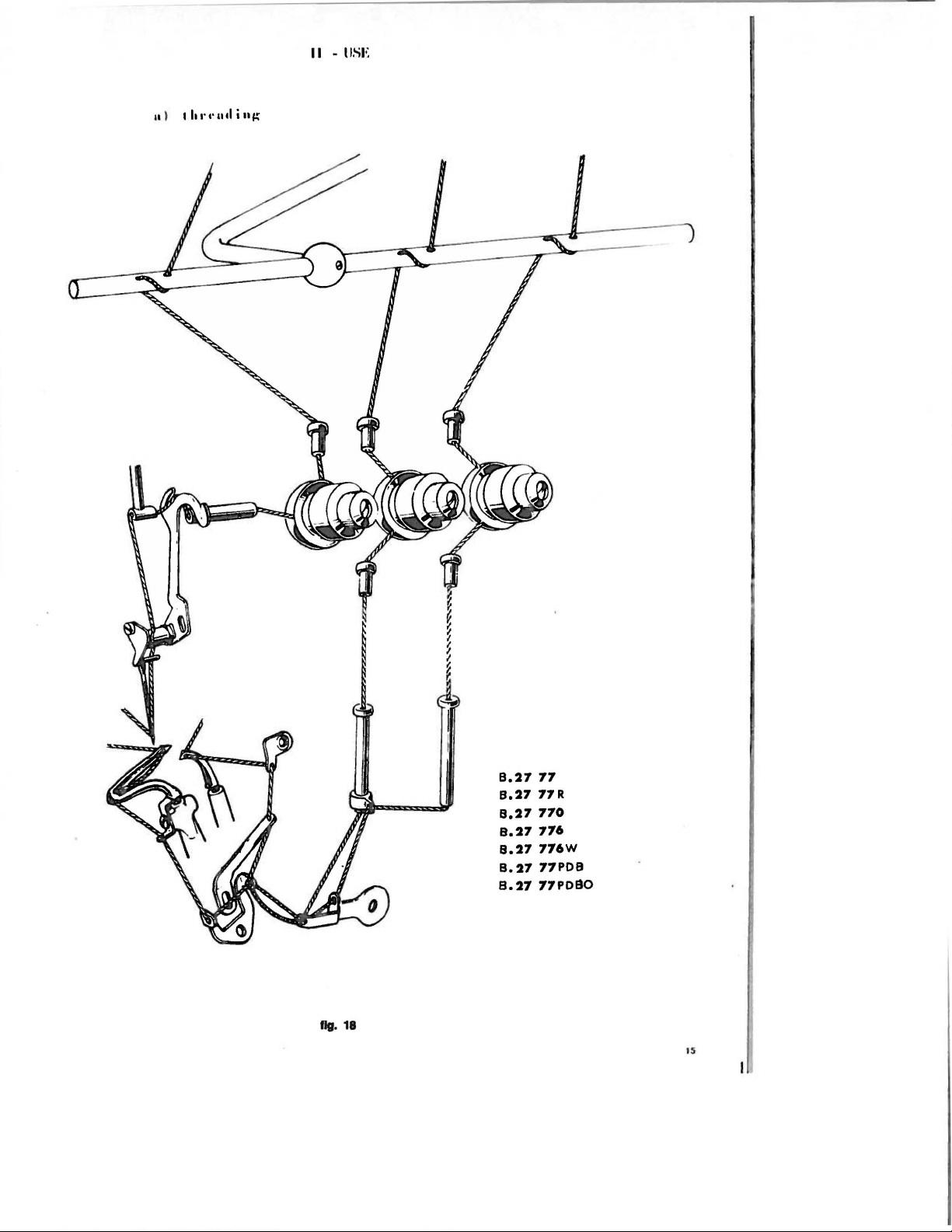
II - liSE
8.27
77
8.27
77
R
8.27
770
8.27
776
8.27
776W
8.27
77PDB
8.27
77P080
llg.
18
IS
Page 14
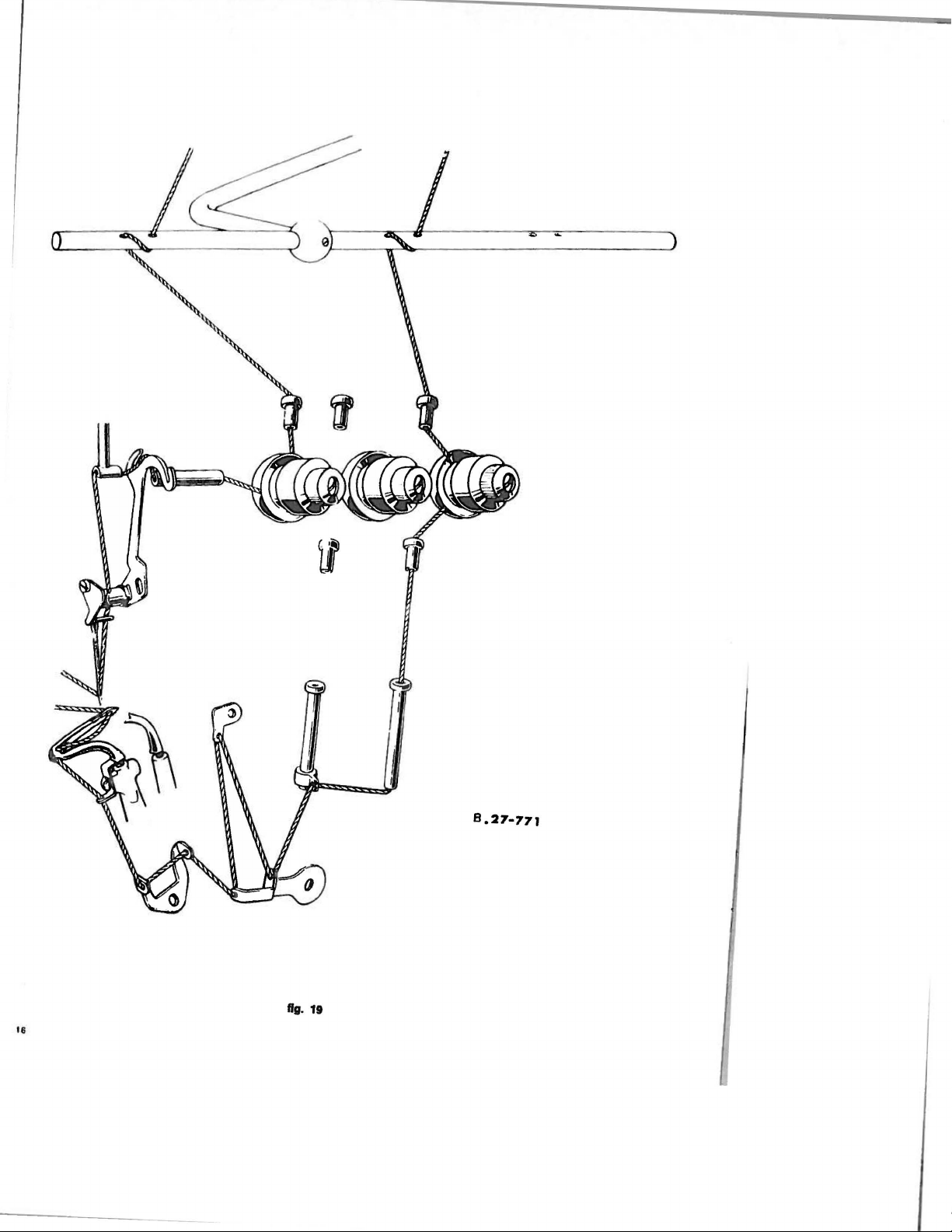
~
'
8.27·771
fig. 19
18
Page 15

b)
t:luu~i•lf(
-
Rotate
is
Prees
out
-
~oosen
and
lnaert
facing
mu&t
ned in
needle-holder.
Retighten
c)
d)
S.·ll
-
-
llu•
"'"""''
handwheel
at
Its
highest
down
on
the
needle-set
needle.
new
noodle
towards
taken
its
upmost pos i t i
lever B (f
that
presserfoot
remove
be
needle-set
So·
II
in~
I
ho•
lll't•
-With
presserfoot
point
enters
-Loosen screw F
-Retiyhten screw
To
increase or
N.
633-7112,
-Retighten screw
inA'
Tighten
Do
not
and
of lt•
the
tighten
tension
clockwise
position
holder D (fig.
rear
with
of
the
.
ig. 22)
scrow
scarf
the
needle is
screw.
s;wl'l'unl
arm D (fig.
presserfoot.
(fig.
22)
F.
decrease
turn
knob
G.
u.•<iuninA
too
tlist·s
discs
mucn.
until
needle
and swi
18)
.
by
half
of
positio-
within
needle
machine. Care
on
18)
and
center
the
pressure
A (fig . 22).
(fig.
21)
ng
turn
the
locked in
presserfoot
of
the
sufficiently
B
position,
in
relation
presserfoot,
as
turn
handwheel
to
the needle.
loosen screw G
to
permit a regular
clockwise
(fig.
22) with wrench
stitch
till
needle
formation.
e)
S1
ilc·h
lt•n,:tlh
-Unscrew
-Loosen screw L of
-
Set
shortened.
-Tighten screw
-Replace cap
f)
Ad
jusLml'nl
Tne
to
-loosen screw N
-loosen screw F
-push upper
width of
-tighten
-turn
N
-Activate
sure
aga i
-Retighten screw N
screw 0 of
width
change
handwheel
(fig.
to
nst
capT
of
the
seam
screw F
13)
lower
the
screw A
mljuslmcnl
of plexiglas&
eccenter.
stitch
L.
T.
of
st•am
widt
the
seam
needle
plate.
of
lower kni
(fig.
knife-holder
cutting
17)
(fig.
clockwise
knife
holder so
edges
(fig.
(fig.
(fiA·
16)
plate.
length adjustment. Rotating
h
may
be
block A
17)
till
13/
3)
adjusted
To
vary
fe
holder
knife-holder
that
of
the
when
setting
the
(fig.
(fig.
knife
trimmer
to
a very
width of
13)
17)
to
block A
holder
knives.
the
trimmer knives.
to
the
right
limited
seam
right
is
within
or
left
in
extend
its
pressure-spring
At
no
time should
(clockwise)
beyond which
these
very
in
order
uppermost
wil l apply
stitch
fine
to
obtain
position.
pressure
it
limits
the
be
length
is
necessary
:
the
required
Loosen
correct
applied
is
screw
pres-
17
Page 16

f)
Irregularities
duo
to
improper
horulling
of
machine
n
1
2
IRREGULARITY
Irregular
Feed
slipping
stitch
fabric - lnsuH
and
sidewayo
PROBABLE
- Tensions badly adjusted
-
Thread
- Incorrect threading
-
-
-
-Differential
take-ups badly adjusted
Yarns
not
gauged
ic
Feed
Knives
ient presserfoot pressure
dogs badly adjusted
need
sharpening
badly adjusted
in
CAUSES
height
and
slant·
-
Skip-stitchiny
3
Thread
4
·--
breakage
-
Primary
consequently blunting the looper
Loopers
-
-
Loopers
- Front needle guard too
-
Needle
-Tensions
-
Yarn
irregularly
-·---
--
or secondary looper badly
too
far
apart
at
too near
at
badly positioned
too
taut
wound
crossing
crossing with consequent blunting
far
from
on
reel
adjusted
needle
in
respect
to
the
need
1 e
Needle
5
Puncturing of fabric
6
Loss
7
8
Lack
18
breakage
of oi I -
of lubrication
Keadle
-
-
- Blunt needle
-
-
-
-
-
- V-belt incorrectly
-
-
bent
Needle
badly
mounted
Needle
gauge
not
low
pump
suitable
filter
Needle
with unsuitable point
Screw
joining base
Pump
plug not tightened underneath
Pump
gasket badly arranged
level too
Oi
I
Upper
tube clogged
Luor
ication
and
pump
mounted
clogged
for
plate
not tightened
underneath
- ---
Page 17

II.
M A I N 'I'
I
1•:
N A N C I•:
a ) E v 4'
Clean
1.
Clean
2.
Open
3.
Clean
c ) E \ 4'
I.
Wash
2.
Wash
3.
Blow
~.
Fill with fresh
d ) S
Sharpen
J'
) d
11
y
the
feed
and
stitch
formation elements
thoroughly dismounting feed dogs, rear
front cover plate
the
inside
,.
) I h
the
oil basin
the
pump
filters
pump
and
filter
and
carefully clean the front opening.
of
the cover plate containing the needle
•.
4' 4'
Ill u II
I h s
with
kerosene or other
with kerosene.
with
compressed
air.
oil.
l111
1'114'
II j II
A"
I lu•
1,.
II
j V 4' S
the knives using the
RIMOLDI
knife sharpener
exact angle of sharpening. This block is supplied
e )
Ins
I
1'114'
I i u
II
r u
I' , •••
m u v i II
A"
-Tools
necessary
- Pincers type
- Pincers
- Extractor S
type
S
S
sup~lied
0560/00
0~59[00
0~16/00
on
request only.
briefly.
and
front needle guards,
commercial
cleanser.
and
on
request.
I
h..
•.
u m
and
primary looper.
movement
assembly.
using the appropriate block
shu
r I
that
guarantees the
It
is absolutely necessary
tial
position. Therefore
Reassemble
-
-Leave
-Connecting
head
-
The
rod.
The
handwheel.
-Carefully
flanges G
all
locking
rods J and
of
connecting
positioning
The
two
assembly
cuts are
positi
observe the order of
that
proceed
and T in
screws
of the connecting
L are distinguished
rod
Land three lines
of
the connecting
on
the
on
of connecting
I M P 0 R T A N T
the
main
as follows:
the lubrication hole, towards the
same
assembly
elements of the shaft-connecting rod, are re-assembled keeping
rod
cao
in
from
on
rod
side of the part.
the surface of connecting
cap is determined
rod
N is given
of
the
their
oneillotherbythe
by
a cut
by
the
drawing
cup
springs.
bottom.
own
holes.
number 2 engrayed
made
number
rod
both
J.
on
that
the
must
on
the surface of the
body
of the connecting
be
on
the
part
ini-
of the
19
Page 18

I.
Pushing plunger
Remove
2.
3. Pushing plunger
~.
5. loosen the
6.
7.
8. loosen screws of ring F.
9.
10.
11. loosen hexagonal screw
12.
13.
1~.
15.
16.
17.
18. Diaaaaeable
11.
screw
Remove
flange
Remove
ball
Take
out
Remove
caps pf connecting rods
Remove
cover Y
.
Take
out washer
Extract
Remove
Pull out
Remove
Extract
Re~ve
handwheel
flange
cup
snap-on ring P
ahaft.
bar,
z.
bor. turn
G.
two
eccentric
bearing
spring D of
from
W.
Y.
T.
spacer
U.
springs
aection K and
A.
handwheel •
S.
SEQUENCE
turn
handwhool
hondwhoel
screws
washer 8
regulator
X.
by
means
Q.
C.
and
E,
N,
of
OF
OPERATIONS
reference
reference
eccentric
using
pincers
0,
J,
and
pincers
No. 5 opposite
No.
P oppos i
C,
using
S 0560/00.
L.
S
0~59/00
extractor
moving
te
of I i
of
the
nc
marker
line
marker
S
0~16/00
shaft
.
sligtly
on
on
to
machine
machine
the
body.
body.
right.
20
Page 19

SPARE
PARTS
CATALOGUE
21
Page 20

u } I
11
I. fhc spdrc
ous
part~
r i
2.
In
order
rosilion
3.
The
conversion groups of the
i n G i
ny
q,
On
each
by a
number.
ferenced
number
&upplieo
5.
Thu
catalog
order,
pnge
number
b)
Jus
I.
If
the drawing
the
general index.
2.
If
the drawing
position
tables
I.
llfiW TU
I ,.
••
eln • I i u
parts
and
to
make
of edch group
I e tab I
table
the vdr i
The
oy
capital
with
an
if
required
is
thd drawing numbers of
of tha
I
I'
II
I'
inside
the
relative
11
catalog
groups
it
e~.
groups
dsterisk
is
which
is
easy
inside
ous
whose
letters
are
for
special
groups
completed with a
table
in
I i
1111
''
number
number
the
page
is
known
of
a component
machine
is
liSE
TillS
made
up
of a series
make
up
the
to
use
this
the machine.
basic
machine
of
components
parts
cannot
of
the
seaming
general
all
these
its
known,
found.
alphabet.
the
position
not normally
which
is
easily
f:ATAI.tl4;
basic machine
of
catalog
and
its
illustrated
be
subblied
The
supplied
operations.
index in which
component
parts
are
is
immediately found
is
not
known,
by
consulting
taoles
and
the
index of
subclasses
separately,
parts
cross-referenced
with
the
parts
is
of
illustrated.
but
only
the
illustrating
its
subclasses.
tables
are
illustrated
are
cross-referenced
are
machine ana can
given,
the
illustrated
in
machine and
by
consulting
its
approximate
the
va-
shows
the
cross-re-
by
be
numerical
the
index of
a
a}
A I I
I.
To
~uarantee
necessary
2. give
3. Jive
4.
write
5.
The
The
irregularity
that
u)l\e'l'!il~
1.
On
the
be
used.
2.
The
3.
The
gauge
calculated
11.
The
5.
It
is
the
of
In
case
6.
qu
ired should
7,
Sp
ec ial
otic
to
the
serial
the
drawing
in
full
quantity.
Rimoldi
these
machines
needle system
indicates
on
system
and
advisable
needle required (ex:
of
douot a sample needle
ball-pointed
ised fabric&.
II.
HOW
ru
I'
I
...
an
carry
the
Company
found
parts
immediate
out
number
number
name
are
the
of
of
of
wishes
on
parts
sent
des1
foliowing
the
machine
the
the
part
M P 0 R T A N T
to
be
produced
with
only
illustrated
and
gauge
the
the blade of the needle.
the gauge
when
placing
be
attached
needles,
in
are
average diameter expressed
are
also
orders
100
to
the
SUK,
TU UHDER SPARE PARTS
dtch of
part
the
this
marked
needles gauge
the
spare
rules
exactly:
reauested
itself
able
to
analyse
by
order
stamped
or
order.
are
t~em.
for
spare
manual
to
on
the
on
always
straight
shank
the
state
90
empty envelope of
available
parts
any
case
For
this
parts.
RIM
of
the
In
hundredths
envelopes
clearly
system
for
seaming
required
27
RIM
the
it
of
breakage, wear
reason
please
needles
needle.
of a millimetre
of
R imold I .need
the system
27).
type
of
needles
on
elastic
is
directly
ensure
only must
lea.
and
gauge
or
ela-
or
re-
Page 21

INDI
BUSSOLE - PASSAFILI
SPINE
NELLA BASE
- FORZATI
CE
TAV.
TAV.
DELLE
1
2
TAVOLE
ALBERO
CON BIELLE
GRUPPO
DIFFERENZIALE
ALBERI
COMANDO CROCHET
PRINCIPALE
E BIELLE
TAV. 3
TAV.
4
GRUPPO
BARRA D'AGO
GRUPPO COL
SUPERIORE
ED
MOVIMENTO
INFERIORE
TELLI
TAV.
TAV. 6
5
25
Page 22

MOVIMENTO
ALZA PIEDINO -
PLACCA D'AGO
COPERCHI
Plllt..IO
01
LAVORO
PASSAFILI
E TENDIFILI
BACINELLA
E POMPA OLIO
TAV. 7
TAV. 8
TAV. 9
TAV.
10
.
01
'.
'
PIASTRA SUPPORTO
MACCHINA
E GINOCCHIELLO
PORTA-BOBINE
E PEDALINA
ACCESSORI
TAV.
TAV.
TAV.
12
13
11
:
=~----='
-~-$
~
-~·8-
---.
.
...
":
Page 23

CLASSE 8.27.77 R
CLASSE 8.27.770
TAV.
TAV.
14
15
CLASSE 8.27.771
CLASSE 8.27.776
CLASSE 8.27.776 W
CLASSE 8.27.77 PD8
TAV. 16
TAV.
TAV.
TAV.
17
18
19
TAV.
TAV.
20
21
CLASSE 8.27.77
DISPOSITIVO
PD80
TAGLIA CATENELLA
ELETTROMAGNETICO
w
21
1
Page 24

1
...
RIP.
1 270 016 bun ola pl'r perno co nlondo
2 270·097
J
•
5 270·768
6 270·643
DISEGNO
770·0SSII
270·057/1
...
11
bu
nol
a
p~r
bu
buuole onten
luhclli puuof
$1JIU
porto colt
uole po:.lenon p
prr
•I I
DENOMINAIIONE
er perni de1
ori
ptor
pern
th
per fil, dc i
vf'
llo
ol
ello
o
barru
!oUJJt!fiOf~
,
dei
creche
crochch
d'ogo 1
crochets
IS
l
1
2
2
2
I
N'
RIF.
1
270·644
8 270·912
9
270.04~/2
10
270
11
270 642
...
DISEGNO
042/l
bun
ola
Spinello
bu
n ola per
bun ola
spine
DENOMINAIIONE
ov•da
golleggiante
di
fermo
perno
de,
.tro per cliRerenz•
per
ct'ntraluro cortor
per
piano
d1
del
Iovato
differem:•ole I
alc
30
i
8
1
1
1
2
Page 25

26
--1--
..
"
I 2
:(; /
\
~
/
" ( )
7
2
14
N"
DISEGNO
RIF.
1 PM.27.77-009
(A)
270
012/1
(B)
270-116/1
(C)
270-061/2.
(0)
27.77-060
(E) 270.060/1
(F)
271).009/1
(G)
270-707
2 270.704
3 270.705
4 270-620
5 270.614
6 270-008/1
7 270-612
8
270.981
• 270.608
10 270.610
11
270
-617/1
--
N"
olboro prlnclpolo comploto di blollo 1
blella
biallo
biello comondo
moni
rnonlcotto por
otllfl:tO
cusc
anello
malic
flangio
dls.tonziale
volontlno 1 25
rondello
Yi
le
coperchio con volontino 1 L
perno
nllorl
DENOMINAZIONE
comondo pOrto ogo 1
comondo
cohollo
supttrioro 1
crochet•
colto
per
blolla comando
bella
pr
ncipolo l 18
netto
a slore
destro
Seeger por cusc lnetto
o lozza
per
Iota
destro
deslro
per allxoro
con
guido
fis.so
Yolontrno
per
volontl
no
eli
biloncl
omtnto
comondo
pa
r o l
bero
porto
crochet
porto
destro
principale
prlncipole 1
sup 1 16
crochet lnf. 1
2
2
l
.4
1
1
1 H
1 M
2
73
26
14
15
17
19
20
21
:1:1
24
:ti1
12
13
15
DISEGNO
270.999
01
G-H
·I3 7
27(1.97
5
004 E-7
092 0-15
270.615
27(1.010/1
07~
A-12
270-
722
073
M-10
0160·5
270.938
011
c-•.5
001
E-10
010 0 -11,5
270.613
709
270-
270.062
PM
:'1 n Oh0
PM
. 710·060 I
N"
viti pot s.elton d•
viti pe r biollo 270.010/1 o
vit i p
viei Iissa covollolto
s.topplno
custodia
bunola
rondollo per dlfterenziale
onollo
rondollo
viti
vito
viii fiuo spinelte
vii i par flonglo
viti
Dbtanz
ru
scinallo a sfere
cov
bielle com a
b•ello coma
N.B. I cuscineltl con
uro
l'ordinoztone
il
meri Romani sullo
nelli stessi.
OENOMINAZIO~IE
bilanciomcnl"
or
monlcot
H
per
olboro principahr
pelt
olio
lntermedia
di
te-iJ•slro
per
olbaro
per
onello dl registro
Ossa
buuolo
lata
par
b•ollo comando crocho1
lolo
per
cuscinotli
o11
otlo
per
b.ello
ndo
porto1
ndo
poria
fornili come riccmbi s.toc.coti, rna nel-
blwgno
numoro di s.elezione contrassegnato in
per
b:ello
per
o1bero
eccentrlco
principal•
inlermodio
destro
slnislro
crochet
crochet 1nf.
riferlmcnto
anolutamenlo
corona
27(1.116/1
print
regolobile
per
albero
1.up
.
G possono cs-
cslorna
del cusci-
pole
indicate
princ.
nu·
4
4
4
2
1
I
1
1
I
I
2
1
2
3
8
1
1
1
)
1
32
Page 26

N"
RIF.
45
N"
DISEGNO
DENOMINAZIONE
.
N'
I RIF.
80
N"
DISEGNO
70
DENOMINAZIONE
71
3
72
1 PM. 270.049
2
277·DSI
3 270.977
4 270-640/1
5 092·8 I
6 270-937
7
277
·DS
7o
"277-0521 S
8 270-611/1
9 270·979
10
070·M·4 5
II
270-035
12
4030·06
13
007·C·II
14
270-048
IS
07J.C.8
16
270·
0!4
17
071
·M·5.5
18
270.
~47/1
IO
070F
20
Q57
.f ·4
21
270.975
22
270·039
7.1
092·0-14
24
071
·H·S
25 270-036/1
26 270.935
27 026·C 7
28
PM.
270-038/1
(A)
770.046(1
(B)
270.038
20 270-040
3~
770-
031
31
002·
0·6
32 092 -0·
33 270-o.tl
34 250.471
~S
D17E·11,5
36 039 H·9
37
064FS
38 270-992
39 270·281/1
40 073 A·8
accopplamento
gr.Ra t.uu ld.Dfio
v te
squodretlo
,
loppino
vile
gr
2
.4
12
lffino
Qrtflino
blocchello a.corravole
vile
rondello
bunolino
Iosee
v1
1J
giunto
rondello per
per
no
rondfllo se11ore I
sellorc
rondello
dodo
vile
pe:rno ec:cenltlco del d fferenzi
stoppino
rondollo
blocchello
rondello
vito
$.CHore
cursoro
$.ellore
ollocco
$.pina
stoppino
stopplno
perno
vile
viii
vile
rondelle
v11i
sellore
rondello
slitle
dt l dtftercnz alo
fino griRo
fino
r.~W)
Ito
per
per
per
per
per
per
liuo
per
per
:iUUid1orio
di
guido
ptJr
perno
dol d•fterenziole
(montara
con plocco 277·
gl
per
per
fonf!lle
per
per setlora
Incr
per
~rno
MUOf'tl
per
per
scorrevole
d $.pollomento
rondolla di
per
per
per difi
per
otloc:c:
per
par per
poSieriore
ollocco
eccentrico
seuore
ptr
sellore
superiore
per
per
unlo del difterenziole
giunll
del
difterenz~ole
ilillo
del
11itlo
porto gri
perno
poster
inc'fml!nlo
ncremento
emento
ropporlo
JMtno
rapporto
270·054
perno
eccentr
perno
d.l
diRr
per
\pollomento
cunore
d.Rerenr l
ale
erenz&al•
biollo dell'rc:cenrric:o regolobile
a o for
cello
Sp&nOIIO
no
posU:rioro dol difterenziolc
del diReremiole
regolobile
comondo dlffcrenriole
seuori
limite
del
dift'orenziole
limUe
perno
comondo diflerenziale
d fhm:nz1ole
d•florenzlole
ioro
diflt-re~nrtole
c:ono
coua
Jl1
110
ffo
suuldiorio
del
dtfteranziole
dlfferen.zlole
differenziole
difletenz•ole
ale
co
renziole
del
diRerenziole
(deitro)
1l4/S)
difltrenz
ioli
differenziole
diflerenziole
I
I 42
I 43
I 44
~
1 46
I 47
I
I 49
I
2 51
1 52
2 53
2
I
I 56
1
I 58
1 59
1 60
I
I 62
1 63
I 64
I 65
I 66
I 67
I 68
1 69
I 70
I
I
I 73
I
1
I 74
I 75
2 76
I
2 78
2 79
I
2
(C)
(0)
-n
61
71
72
BD
41
45
~8
SO
54
55
57
PM
.270.562/ I
270.288/1
270-567
065 0 ·6
270·568
270-702
270-703
270-037
270·984
070-
B-3
OI
7·C·4,5
270·735
270-045
270-033
270.980
070·M·4,5
270-034
DDS.L-11
270.997
270.566/1
270.641 / 1
270-978
277·050
290·700
270-736/1
270-738
270.737
092
D-16
270.249
270·250/1
270·251/1
Oo.t
L·7
PM
. 270-732/2
270.733/1
270-732/2
271).734
270.032/1
004 P·6
270.928
27().929
270.747
270.943
leva comondo
setlore
•et
tore
ronde-Ito per pomolo
~molo
onello
gobbielto o
blella
vile
rondello
vic
regolotorc
ollacco
giunlo
vile
rondelle
buu
viii
vile
leva comondo
squod
vi
le
gri
fl'o
ont~llo
gombo
mollo
pomolo
stoppmi
corteri
prot
squodre
viii fiu oggio
cofpo
slitta dell'ec:centrico regolobile
corpo dell'eccentrlco
mollo
piasrrina
vile
vile
vile
latdonc
JMrno per blocc.aggio pulsonte
dtRerentiole
infer lore
per
c
on
per
elottico
comondo difforenziolc
per leva
JMr
Iissa spr
per
per
fino g l
per
olino
~r
squadrallo
per
leva comondo
retca d• guido
list.a grlfl'a
pri
ndpole
ela
per
per
pe
per
no
d1
~•o
no
Uo frs
e s
ll
o lu-.guctta
per cursorc
li$.SO
piostrino del
per
slitta
per
si1IIO
per slillo
HmHe con o
indiCa di
regolonu~nto
bloccoggio leva comondo differenz.
rulll
per
blello
del
differenzlole
leva del differenziale
netta
dell'eccenlrico
setlore
del
dol difteronziole
del differenziole
slillo
del d&fferenziale
differemlole
seuare
del diflerenziole
per
princlpolc
por
pulsonte
giunto
del
porto
gamma
per
protezione
protezione
dell'eccentrico
ngalablle
diffcrcnd ole
cursarc
ec:c:entr
ico
ccccnlrico
ecce
ntrico
difl'erenziale
diflerenziolc
differenziale
shllo
unto
g•unli del differenz.iale
par
sti
ca
pulsonte
pulsonte
r pulsonte
prolezione
in
sogglo
llo
c:omplelo
griffe
diR~tentlole
ollungo
cohcllo
in
gommo
regolobile
punta
(sinhtra)
sup~tlore
1
I
I
1
I
1
I
1
I
I
I
1
I
I
I
2
1
2
I
I
I
I
I
I
1
I
I
2
I
I
I
3
I
I
1
I
2
2
2
I
I
34
Page 27

. 1
a-
--
51
8
4
15
·
14
13
..
10
\
9
~
/
N"
RIF.
I
2
3
4 270.064
5
Sa
6
7
8
9
10
N"
DISEGNO
092 0 ·
16
073 N· 10
270.070
27.77·074 crochet 1.uperlore con foro largo
"27DC·D74f1 crochet s.uperf
vo.rnsr2
"270·075 crochet inf. can foro
270.069
250·471
270·068{2
G27.77·065
s.toppmi
rondelle per perni comontlo
lp
no p~r leva cornoN!o
ptrno
crochet lnfe d
perno comando crochet inler l
vi1i
porto
guida osc•llantc con
DENOMINAZIONE
~r
ptorni doi
comondo
crochet
ora
orc
per
leva del
crochet inferlore
con foro larva per
cieco
crocheu
huuolo
crochols
trocheu
I.Upltf
croch.:t
do
re
' upe
per
strnllo
per filoti cotone
ore
o vile 1
iO t e 1
filoti lana 1
filch
lana
N"
RIF.
~
(A)
2
(B)
2
(C)
(D)
1
11
1 12 016·B·4 v
1
13
1
14
1
15
2
16
1
17
N•
DISEGNO
071 B·5
27 77 ·056
77 n .o
os
270·063{1 1
270.974/1
016·R·2 .5
27.77·067
097 B· l
27.77·314
092
0·5
DENOMINAZIONE
rontiello 1
buuolo
reqolol:ule
QU1dO
0"1llon1•
.....
porto
crochet
Ylli
fruo croc hel s
11:1:
f.
u o movimento crochet infer
grana
per
leva comon
stoppani
vile forolo I
slopp
no
s.uper ore
lp
ino 1
do
crochet
1.pina
supenorc
..
,
ore
36
~
)
)
1
2
1
1
2
1
Page 28

r
31
_ _ 7
17
10
\
N'
RIF.
2
3
•
5
6
7
8
9
10
11
12
1J
14
15
16
17
IS
I
N'
DISEGNO
PM
270·13~1
PM
270·132 1
270-132
220-728
2Q0.027
270·933
270-713
270·006/1
073 F-9
270-719
007
C-11
27.7J.C'IJ7
270-975/1
270-13<4
092 [).6
071
E·S
001
G-10
270-708
DENOMINAZIONE
lf"vn a forcella
perno
per
leva o forcella
bunola
per leva a forccllo
Illite
nssa
bu
u oln del c
,
no
del
nlhero
bero
ollncco
no
nlbe
olbe
ourllorr
gu
1
cia
porto
perno
porto sllllo
supr.riorr
llo
ro
~uperlore
ro
~uperiora
ago
porto
ogo I
nnello
per per
cfocto
per perno ou do porto ago I
rmello
elosticu
olbero
comondo leva
per
ronrlelle
fo~ene
por olbero supcriore
per foscette 2
VI
II
ollacco
per o l
v i
iCt
per ottocco
ip
jnot
to
..
itopp
lno per l P i
ron
r4e
llo
"'"
Yf
iC
per
rondello
cu
sc<
neotlo
per
N'
RIF.
~
I
I?
2~0.708/1
016 B-2,5 Yl
1
2a
1
21 c 27
{A)
I
27
I
290·025/1
tBl
RIM
n
003 A
23
270·130
I
~·
0'12B
25
2
016 A·
26
2
~7
270-135
I
28 092
I
29 270-133
I
3D
011 r.
I
Jl
001 £ 7
I
32 270
I
33
092 D
I
J•
092A·IO
N'
DISEGNO
77-025
77 020
27
4,5
·I
2,5
OS
J.s
Ill
II
DENOMINAZIONE
gabblrllo a rull
llt f11o
gruppo
Monello
Borro ago
oqo
VIle
sp111111o per morsetlo
"
oppi
vite
levn
s.tontlino per
splnn P
grnno
vi
tc
ro
ndelto ch
llcpp
)toppino
l
per
leva
S0
spina
boT
ro ago c
porto ogo
per m':lr!.
elln
no per
spuM!IIO
'"no
c::omo
nrio
shllo
""'
spmollo
I!'
' leva a forcf'llo 1
r.
ua
lo
v<'
pe
t
tt
lbc
ro
rosomento pt!r
<nn
..
,
per no
comondo
on
morsrtlo
~erro
ngo I
porto
ago
porto
·
ago
"•I
porto-ago
comondo
barro
!.Upetiore 1
gabbiella o rulli
ago 1
. non
scompon
d'ogo I
38
. I
i
I
I
1
I
I
2
I
I
I
I
1
I
Page 29

10
8
7
9
;
12
I
13
\
,
..
'I
14 15
/\
/ \
' I
~
---=·
16
N"
RIF.
770
210 096
27 11· 112
"21 77 ·
277·110
•
270.111
5
210.987
6
7 710 099
270
8
9
07J.F.9
770.71Q
10
m1c.11
11
270.109
12
300008
11
1A
092 C·2
09?09
15
N"
DISEGNO
10='
1121
101
5
31
pofln roh
(lf'
f U O
pf'l
pnrtn
cnft~llo
cn
ltello
~uPf!r•nrr
co lt
ello
Jou
pt>ro
cortcr
in o pr.r port
cnne
rmt.
per (OIIto
Vtlf:
fi
u n
rnlt~ll
:-
rhelln 1.0r1o cnltello
rJin
nn~elln
f1\
.loO
cnlt
,.,
rr:nrle lt n
fnueolln
..
,
vltl prr fc
i1Cf'II
.. ,
1P
Ot'll
n
n
tlncro o fo
rcf'llo
P"'
'
per poria
1pinettn
s!Ofll""
~o
topp1n
DENOMINAIIONE
ello
~u
'unPrior,.
cnn
rlentnt
nr e 'en:rn tient
roltello
o
llo .lollpNinre
o
~urMrinre
suncriore
r.ll
o
.~o
upe"ore
p
.or
tn
cn lttollo
po
rln co•tello
O
CliiO
CCO
forct>llo
cohello
per.ore
urn
nturo
.1ouper
SU!')I"tiOtl!
~uper,nre
ore
,.:
~
g
N"
RIF.
. 16
:18
30 71
31
29
DISEGNO
250·•
1/
001?
07 1
D-5
18
19
270·1
210.10S
20
~1
211·113
n 270 ·100
;1]0.106
~J
24
003
l
2S 770.
101
070 F
26
?Jn
QB
27
o2•
n \
00.4
A·~
29
11-n&
'}
7 77
""'
N"
11
10
0•/1
l2
.4
B
117
~
0"
\ \
26
DENOMINAIIONE
vi
te
per
le
va
cl.-1
croci~
vi
le
r.
..
m
colu~lln
ronrlelf n n
er
,
,orin
·coiJell
ln guu:fn
ncfelln
rlf'r ,.,orin
por
pN
o
tn
cohrllo
mferiore
coltello inferiore
I'C'
rtn cohe-llo
nr.r buuolo
pprno
cnltell('l
molln
puntnlinn
vita fissn rm
huuo
rr:
v•le per coltello •nferiore
v•l~
v•te fin n squndratlo
1quocfret1n te••uto s.pingi 01olo
1quoclre-1to tet'tuto
perno
inferiore
porto
1upporto
CC"'Itrllo
,:,~Iva
I
inferiore
dpl
coltello
infe-riore
collr.llo
inlenore
coltr.llo inferiore
del co
~ouperiore
OQO
21
1
27
infedore
hello
6
~
supcrtore
infenore
~0
Page 30

--
14
24
w
DISEGNO
RIF.
I 270 077
2 270-081/ 1
270-083
3
..
072 L-7
072P
5
6
270-087/1
7 270-9
270 0
8
9
270-714
10
270-
701
II
28.778-076 l
12
27.01P-403/1
27
26
13
..
210
""~II
15
270-091
16
004 L·9
17 27.77-1
18
27 77· 196
~
1
I
I
I
I
1
1
1
1
1
1
1
2
1
I
1
7
22
t/28
w
lpina
per
no
buuoln
7
85
9'1
/1
186
1J
rom!wllo
rcncft.ll
lr
vn nl1o
VIII!
ma li n
" ' " " • IDE
onello el m lic:o
c:
vo
VIII! f
iquodrello
perno
ght
ern
vile
p
tos
lrm
slo
Ro fiuo piedino
DENOMINAIIONE
per
leva
porln pitocfino
per
leva
per
levn
onlrr.nre
n po,IP.rtorv
p1~1inn
lrvo ah a p•rrfi
per
l
eva
AL
• p
oprib
ile
porto
.u
o
u
~uarirello
di
ferm~
ptrr
rcgolo
ziont-levn
per
bunola
guetto
del pi
lin
o
nha pirdino
oprib
i le olzo pt
pemo
llfll
per
per
no
pi e
dina
nl:o
t>r
porno
pied
ino
del
piedino
di regolmi
('cf
ino
edino
no
abo pirdino
abo
pfedmo I
one
N'
RIF.
i
1 19 27 77
20
I
21 27 70.184
I
22 G 77 77·
I
23
I
I
1
I
I
I
I lmontorrt
I
23<
24 27.77. 107/1
I
25
26 270-934/2 vile f n o salvo
I
I 27
I
28
I
'/9
30
31
32
23 a
w
DISEGNO
191
27 17.
10'1
/ 1
181
27.77·11~
'27
.77-
1141
.
'27
.77-1145 ploccn ri'
'27.77-114/S
'277-114/S
'27.77·1142
270-
936/2
092 D-
11
032 L· 10,5
DOIA-l ,2
271-185
270-
073
PM
270-091/1
DENOMINAIIONE
lln
'l)
ucllo
dol p
~alv
a
~tllla
p
ed
lfl
plocca
placco
(mcnrore
plocco ri'ogo · larghon:o
placco d ' ogo · lorghezzo
plocca
1oplng•
vile rtu O sp1ngi osoJo
1otopp
VIII! ft1SO
vHe fino pl
pfcnlri~ta
tubetto
per
no
edino
ago
del p
edmo
o CCYnplelo
ci
'ogo •
larghena
·
forgheuo
-
lorgheuo
caner
grlfrmo
lorgh~uo
ogo
perno
ci'ogo
cuciluro
cucitura
cuci1uro
PM.2B-774-20B
cuciluro
cucituro mm. 6,3
217.0S2/S)
cuciluro
piedino
C"fooo
ago
c.on
con
d'cmo •
asolo
ino
del
pfOCCO
allrina
guido colenello I
levo olza
...
mm
6.3 I
mm.
4,7
mm
. 9
mm.
8
mm.
3.3
42
Page 31

411
110
~-.
\
If
1
\
2
32
~
-3i'
..
.
I
I
8
I
\I
47
I
N•
RIF.
1
2
3
4 270-241/2
5
6
7
B
9
10
ll
12
13 605-412
14
15
16 270.086
17 270-078 sp
18
19 270-993
20 270.995/1 viti
21
22
Zl
24
25 270·247
26
27 270.090
28
29
30
N"
DISEGNO
PM
270·208/2
'PM
20 774 200
007 H
25
PM. 270-205/2
270.965/2
270-9
113
PM.270·?18/I
007 R·7 ,5
PM. 270.245/2
270-206
270-093
032 F-9.5 vila
270
-094
270.701 onello
27
01
p.Q92
270
-066/1
026 C-12
026 E-10
026 G-7
PM
' 70-095
270-248
270-940
PM
270.2iO/I
44
DENOMINAZIONE
CCN"htr
lnlnralf!
con
cnrtltr lnlnroht con huuolo
(mont
vile
PC'
coppello
cupollnn
guornizion
vile per fiuOijlfl o cnp
utrniero con
vile
per finoog o f» as
ptoSiro
uvorniziont! per p os
JlOmolo
per rnndt
r
onde
Ito
leva blocco
rlmtico
motto
per lironte
ina
per
mol lo
prem
vitrt di fermo per o
fis~n
ID
tlPi poUoriori
vi
le
fLSs.o
vile
f•u
n losselto per bose
vile
fiua
carter
poco
borro
do oll i
tironte
blocca piod
tauello per
Ieppo
pc~r
pi
CV10
di
hunolo
ore con nlocco
cntlc:
r supt!r i
uu
ola puuof'ili
h
con
rlo
spt a pe<
fl
rxt
r cupolino 1
pe
tubelti
con bu
no
la
per
lro
per
rpgolnz•ont mollo
llo
eccrnlnca
ecconlr
•c
n I
p1
ed
no I
sbloccn
lava W'ncco picd
1 p tethno
l:rn piedino
cnrlcr
s.uper ore
par bun ole dei crochets
carter
para otlo 1.
carte
r poro olio
olio I
neomanlo
no
chiusuro
foro del
lovoro
nella
perno acccnrrico
camp
27 .77-114
5) 1
ora
ol
io 1
llo
tra
con cupol1nn
cupollno I
pied
ino I
mo
piudino
base
rle:l
cf
eto
ifl. I
N"
RIF. DISEGNO
I~
31 270
1
I
I
I
I
7
I
I
I
I
I
I
1
2
2
I
I
I
I
I
I
-97
32 270.7JD
33
270·220
PM 270·2
34
007 F
35
36
270-221
37 054 0 -4
270-226
38
39 G 270-
40
028 E-10
41
270-212
42
001
0.6
001 [).4,5
43
44
270-718
45
017 F 4 5
46
270-030/1
47
270-973
48 270-715
49
270-129
so
270.
731
51
270-231
52 01705 0
270 913
53
54
270
-214
55 057 E-4
56 005 M-10
270.619
57
270624
5B
59
270.623/l
60
005 E·
61
G.
270.216/l
2
14
242/2
1 I
l3
/'
/
/
'
-
61
DENOMINAZIONE
v•te
lun
go
fi
chius u ro
tO Ptl
r
sporte
rtello con nlelt a
pee
!.porto flo
pt'r
sportello
~r
VIle!
ile
rh
fermo
lro
complotn
pmstra
P<'
fino moll
fissn mol
porno
per
on
ello
po
ct
.
ch
ius
COriO
fi
na
fl
u a
rch.vlto
cl
~
cluusu
one
fss.o
sport
tto
per
fermo
per
Vl (f!' di
ti
per
flanglo Into s10is
gru pe r Iota
per
rii rh1us
per
dis
co
rlollo
nnlerl
n o mocchlno
foro
per gu
ld
o
i e lube
ore
rf"
ano
rno d•R
no
-093
no
re
erioro
le
tro
olbc!-
ro
ro
lo
e
onteriore
ll
lovoro
el
i lovoro
rto
usuro
s
u~riore
o
erenziole
llo a
ntenor
onteriorc
fer
mo
di
flllt s
porlcll
di fihr
infer l
o
lo
del pi
uro
scdc pc
u o
m:xch
pom
olo
270
per perno gu do po
ro fori del dispositive c W •
pe
r corteri
elfo t:nler io
spo
rlolto
ont
c.orte
r l
otero
f
ermo
sinlstro
disco di chi
uro
foro
di
chiusu
nro comple
ago
t
nppo per
17
pcrr
spo
Ytlft
m~llo
dodo
v
plo s
vati
mollo per ch•usuro piano
vite
v
ite
onelfo per
vit
top
v ••
gra
copa
I
eppo
guor n•z
v
lte
s.
pine
vile d 1
dodo
v1
f1on
guorniziono
d1sc0
v1
1i
'
PlJ
·I
J
1
1
I
I
I
1
I
I
I
4
I
I
I
I
2
I
I
I
I
2
I
I
' I
1
I
3
I
I
1
2
1
Page 32

p
30
~
24
28
9
II
1
1
1
1
1
1
1
2
2
2
1
1
1
2
1
N•
RIF.
16
17
18
19
20
21
22
23
24
25
26
27
28
29
30
31
DISEGND
270.170
27 00-2694/1
004 L·6
277·270
004 A-3,2
270-276
27.77·275
032 A-6
272-232/1
270-232/1
270-233
270-235
6()3.031
270-230
270·232/2
004N-5,5
DENOMINAZIDNE
viii
per
fiuogg•o lorgheUo
tendi
fll
o de l crochet
vile Iissa tend,filo del crochet superiore
tendi Ia delVIle
fis.sa
s.quadrtttlo dl fermo crochet
possortlo del crochet super•oro
vile fisso possofilo
mollo dwl crochel superiore
mollo del crochet inferiore
bunola
superiorc
li o v11e
pomo
d~•chl
lenaioni
pern
f a
vita
mo
iiD
dull'ogo
vi
le?
inferooro
crochet s.uperiore
s.quodrcrlla
per
tenslone
delle tens.ionl
delle
tension
i
2
1
1
1
1
1
1
1
1
1
3
3
6
3
1
2
N•
RIF.
I
10
11
12
13
14
15
1
2
3
4
5
6
7
8
9
N•
DISE!'NO
270·941
PM. 27 77·263
G.270·262/l
004 A·5
270·274/2
270·264
270·265
270.265/1
270·266
270.268
827.77·171
016
8·2.5
27.00.27.14
036 C·7
27.00-27.24
DENOMINAZIONE
viUt
Iissa possafilo
pa
1 ~
ofilo
preuofilo
vito f i!.SO lens lono dell'ogo
lendifilo
filo dell'ogo
guldo
bunola
possorilo superloro
bunola
ponofilo
bunola
pouof'ilo infet1
tubetli pouofill Inferior!
torghello (classtt
vile
fino
pauafilo
viii
per
land
tendilo per fila del crochet
fif
per
complelo doll'ogo
per
ponofilo
per filo del crochet 1nferf
o dell'ogo
f'H
o dell'ago
fil
a dell'ogo
super l
ore
ore
mocch~no)
lfili del crochets
snfo
ore
rlore
·--~------~----------------------~~.-.-L--------~--------------------~~
46
Page 33

,.
I
I
I
I
I
I
I
I
I
l
--
27
28
26
\
flo
_ o _
__
.!:_
__
_
18
-----
-
---"'
I
I
I
I
10
N•
RJF.
1
2
(A)
(B)
(C)
(0)
(E)
3
4 PM. 270.821 ingronoag lo
5 PM. 270·646
6
7
8 001 E·8
9
10
II
12 271).966 guarnizione
13
14
15
16
17
18
19 270·711
N•
DISEGNO
G.270·816
271).911
PM. 270.016
271).816
270·819
270·818
271).817
l70·820
270·825
028
E· 10
271).813
072M
·7
G.270·001
PM 770·9'16/1
270.970
270
·947 guarnizioni
059
G·6
270·824
270
·815
gruppo
spine-
corpo
corpo
plostrina
Plostrino
coperch•o per
lngranogg
truvenino
anello
viii
vile
rondollo per ingranogg io
rdndello
bocinello
loppo
loppCt con pmtigl1o magnet
viti monloggio pompo
dodi
tngronoggio elicoidale
guornizioru
onello
per
per
par
pe
della
della
per
DENOMINAIIONE
pompo
olio
t'
corpo
riello
pompo
con 1pine 1
pompo
intermedlo
sedo
co conduUore
di
troversino
ingrnnoggio pompo
per
pcrni dollo boclnello
ct.
ino
ronogg f
pompo
condotto
poria ol•o
guarn.zione
ingrarUJmtiO
petR
con
olio
,.,
lappa
per
perni
per
pompo
tenuto
per
porto
oho
per
I
della
pampa
pompo
ingronoggi 1
pompo
ol•o
per
pompo
alto
pompo
olio
per
pompo
olio
olio
pampa
olio
pampa
olao 1 34
por
centroegio
bose
d;
$Carico bocinclla 1
IZZOIO
oho
botil'lella 2
,.,
pompo
olio
olio
olio
•
N•
RJF.
~
1 20
270
2
21
270·710
270
22
23
270
1
24
039 G· 10
I 25
270·
1
26
PM
1
21
004l6
1
28
017 C·
1
29
PM
1
30
270·808
2
31
270·
1
J2
270·
1
33
001 E·l
PM
35
270
271).805
J6
I
31
PM 270·805
27
1
J8
39
~
270·
40
270·81~
~1
270
2
1 42
270·706
43
065
2
1
DISEGNO
·712
·823
·812
829
270·830
4,5
270.826
946
811
270·
·804
1).
810
969
·001
l·6
N•
806/1
DENOMJNAIJONE
onelfo • Seeger •
cuuineu
o
stoono
olbero
comondo
rondcllo d l
vite fiu o
guo
flongio
vi11 fi
viti fiu o f1
f•ltro p
guorn
guornizioni
perni
vile
s
o
gall~gi
QClleviJa
pule
viti fan ogg1a pompo
flongia fissoggio
bocinella
malic o toua
rondello
troninomento
pul•ggio
rn 1100e
per
con
tubello
n o
flono~o
llro
er
pompo
iz onl! ~r bocinella
per
per
controggio bou!
per
r.upporhno
upport 1no
con guido
t.tino
per
gollegg1ante
onte
ante
completo
gga
o per pompo
per
perni
Oangio
porto
pernl
pampa
per
pc!r
per
pompo
per
per
olio
olio
pompa
della
pompo olro
bod
nella
oho
pompa
pampa
pampa
pampa
fihro
della
galleg;
per
olio
olio
olio
botinello
alto
olio
olio
olio
bacinello
lonle
48
~
1
1
1
1
1
1
1
2
2
1
1
2
2
1
1
1
1
1
1
~
1
1
4
2
Page 34

49
45
46
31
47
11
N"
RIF.
G 210.S83
270-585
059 A
270-583
270-459
6 270-557
7
270-
8 270-558
9
270-552
10
270-004
II
270-589/ 1
12
270 588
13
058 M
..
067 H-10
15 27016
051L-10
II
"210-590/ 1
IS
'OOIG-10
19
210
20
270
21
065 l 6
n
019 H-6
23
PM
74
G 770 ·001 2
75
PM 1159
N"
DISEGNO
-5
701
-1
0
971
-~/
1
-58
4
270 001 I
DENOMINAliONE
!
ironte
complete
supcriorr.
per lrvo
bocchelle
ptor
leva
t1
' g
iuntn
conce
one
sedc volon ltno
O(KJ
)
Car
.co n to 1
cono
OO
er
pcrn
r~
n
pr!r
no mc1
c
o11
per
per
ol:o p ed
obn
aha
r•
pe tovol o
nt''
ritoglt
our
o
so:.t
o P •
ht sea co ritn
olzo
lcvn
•
100
r'
ganc•o
~·unto
doch
per tirontc
oumo
cluocf• f u
YOI
OtltlnO
g&unh
onell i rlo\1
pe
rn i
J>f'
bu
sole ·super o
ommonu·zoton
bocchello s
protcz•
rlodi per vii w stegno
rondelle per pi
vall
per piostrc
clod pt!r fln
ronol
l!
v
I•
fno
leva c
oman
suppartn per
ronciclle p
rlodo
per support
p1ostrn
JliDslrn so-.teg
rolrnr.ltn
leva ol10 P•etlrno
leva o!zc p crh
no
p•ert.no
unnc
P•t'rlmo
mo
cdu
no
mncch no
~ostf'gn
o
mccch
~:"g
nO
mo
cl mo
Ostrn
n o tavo1u
gh
P•
'"
ol:r
n p
rei
no
CC
h nn con
no
nlog{i " prnl
ua
ll"
vU
7 31
2 32
2 33
2 34
2 35
• 36
I
I 38
8
• 40
• 41
26
"270.553
'270.554
·,; o
~
•
79
• 7
30
·o
•oo
'270
"270 79
•270·99
'059
37
'00
•770 578
39
"270 5
•270 20
"27().
• 70-
42
• 70
43
• 70
••
45
46
'270
07
•27
u;
' 77().5
47
' G 210·570
;o
·o
DISEGNO
·s
p 8
5 l
0..
..
E 5
M9
G6
56/
• s
70
71
76
7
74
77
N"
busso
1
II
molla
oslo
VIIi J)(tf f1U09Q 0 0
upporto
viti
1ti
11p nelle
oncoro
v h o
d
oc
v
te
leva
a
bero
onello te
mollo
olloc o
lontiera
spina
m
ta
dnco
cuscmo
gi
unto
gmocch tello
r
ondel o pe
NB
quontitO
DENOIAINAliONE
lo
infer l
ore
per o1ta
del diAerenz•o e
pe
r leve
d~l
per ginocchiello
per
g nocchiello
r p
nelte
per
oiunto
pe
ginocchiello
punta
per
per "11i o punlo
per
spinetlo
porto g•unto
pe
g•
nocchiello
mollo
r i
c:
•omo
disco
per
inoc:c.hiello
p r ginocc.hiello
per
b fonc i
porto
sea
per D
norchiello
per g
inorchiello
p r
gmocchiello
complete
a,
to romnnrlo diff.
6 7
8.
pe
zr
o richie!.IO I
per
oua
d~l
differen iole
nocch1e
fo nfiO
ginocchiello
per
ginocchiello
per
ginocchiello
per ginocchiello
ere
per ginocchiello
comondo dift.
9
d1fferenziale
IOVOIO
I
I
I
4
I
9
2
2
I
2
2
I
I
I
1
I
I
I
I
I
I
I
1
I
1
50
Page 35

39
,
__
N•
I
2
3
•
'
6 ?50-143
7
8
9 1146 perno
10 01142
11
12
13
14
15
16 270-157 o•
17
18
19
20
21 TS.
22
23
24 053 H·8
25
26
27
N•
DISEGNO
FORNITO
PM. 250-133/1 oslo possofill
016
f.
5 groni
250-140
PM.
250
-148/1 'ostegno
250-137
250-130 oslo prlnclpole superiore
G.
250-137
001 G-10
001 G·12
01141
AS. 250·140
270-1 58/1 sostegno
G270-157
605-980
605-937
AS.
270.140
20x30
569
PM. 910.914
910-964
910.934/1
G. 910-914/1
CON
o•unto
per
oslo pou ofill
osto principole inferiore
telolello
porto
porta
pt
auo
porto
vile flu o
Ytle fiJ,
so
bose del portofili
ossieme telo•ello
lo
passofil i
so
:~~
le-g
no con
porno! I
sup
per
to
a~os
l
eme teloietto
VI
II
n
uo
di1
CO
porto
pedal
ina
dodo
per
vile o punlo
t.
upporlo
pedoli
no
DENOMINAIIONE
SOLA
oslo
per
oslo
fi
iJ
rocchetto
bobine
ptollo
ou o
per
o,sto
osta
teloi"!llO
bobino
~dolmo
pe
, pedolmo
complelo
TESTA
poria
pounfilo
poria
fil
fili
i
complete
N"
RIF.
l
2 28
8 29
1 30 569
31
1
1 32
33
1
34
1
35
1
36
3
1
37
1
38
1
39
40
1
I
1
1
I
3
1
I
2
3
1
2
2
1
1
35
~\_
~
34
N•
DISEGNO
490/2
910
143 O\
1146 pe
001 G-10 vtte o
270-157
016
f.,
270-158/1
605-937 w
605-980
1145
910.144
G 497
FORNITO
porta
IO
d•~
co
,r
no
OL
IO
v1te sen zo testa
~ostegno
pporto
pomolo 'ligrinoto
riodo
oslo superiore
1eloie11o
33
bobint!
pri nc i
·porto
port
pouoft
fino
te
3
37
2
DENOMINAIIONE
CON
BANCALE
soslegno 2
pole
d 1
bobme
o rocche llo
:~oto
cilindrico
li
..
,
pou afili
oslo
per
spma por
ia
bob
ina I
teloietlo
d•l
trlotello
poria
fil
l I
12
i RIF.
8
1
'
'
5
I
I
I
2
4
2
52
Page 36

13
16
~
I
18
N"
RIF
1 V R 604 o
l
'
4
5
6
7 1158
8 270-857
•
10 270-741
.
DISEGNO
11/5
270 ISS
RIM 27
01
161
6JJ.7.41
1156
N"
2
1
6
3
DENOMINAIIONE
li
o kg
1
cuffio
proleHonr
per
m
OL':
cmgh
o
tropezo (/4
ccccio.
te
-
chith'e
towgonolt:" rio
p
n:o
per
1nfiluturo mocc h
imbulo
per olin 1
ch -•• 1 18
ch1ove a
tuba
chlno
Jir
mm
J
pe(
grono
ma
do
mm
7 1 crochets
170 715 I
~
N'
i
RIF.
8
1
11
1 12 277-113
1 13 27 .77 -112
..
5
15 01160/2
1
16
I diflerenztole 1
N'
DISEGNO
27(>675/1
1161
/2
270
·74 5
270
-743 ch10vr
DENOMINAIIONE
blocchctlo
pe
r-
ofTtlotura
colt~llo
infer
colle
llo
super
COCCIOVi
lct
"
'"
cocc
iov
ite 1
chiovct
e!.
ogonole
eso~nalc
1ortt
iore
vile
do
bloccoggio
mm
do
mm
collelli
. 7
2
000
per
per
12
incremento
uroni dof
,.:
I
1
1
1
1
·1
13
54
Page 37

,..--
- -
6
I
3
--
--
7
5
~4
/
/
~----
I
I
/
-,
/
/
CL.
8.27.77
I
.R
I
I
I
I
I
I
I
I
J
/
r
--
11
I
"
'1
j:.;_
I
2
3
4
5
6
7 605-980
8
9
10
II
N'
DISE!>NO
605-144
01141
OOIG-12
605-
U3
605-723
605-937
250-R-9373 poria rololo
G
057 A-3
27
.77-R-267
DOl
C-5.5
I
I
I
I
I
I
\
~
j/
;,;:
8
DENOMINAZIONE
oslo
'Up(!r iore
bose
Pttf
porta
vitr fino oslo
oslo
onello conlco
supporto
pomoli
dodo
guido
vile
rotolo
felluCCIO
15
I
I
I
V'
20
J
..:
i
I 12
I 13
I
I
2
I
4
I
I 20
I
I
N'
DISEGNO
RIF.
PM
77 77-R-267
17
77
·R-
18A
17 77-196 staRe
14
27 77-191/1
IS
17
77
16
17
18
19
21
1113
004 L-9 vito
27
277 R-
004-G-3
G 27 77-R-
T •
nx30
"'
· '"5
OO
IA3,2
071
piostro ; u
sli
hng
pl
ploslrmo guida felluccio
vile
piedi
181
vi t • fin oqQrO DOrin
p1ostrino
vire f1sso piDSirino
lla
ottro
d
c:l
ria
l p•e
uetta det
fi
no
fino
no
complelo
DENOMINAZIONE
irl
o f
ettucdo
pierlu
lO
ri•n
o
l plrdmo
li
nguello
piastrino
gu
ido cotenello
rotnlo
ll
I
I
I
I
I
I
I
I
I
2
1
'
14
56
Page 38

CL.
8.27.770
3
IN
"
RIF.
1 27.770.052
2
27.770-050
3 27.77().051
~
27.770-11~
"27
.770·
s G 27.770.181
6
27 77-184
N"
DI5EGNO
1141
DENOMINAZIONE
griffino
grlffo princ fpolo
griRa
suu
id1oria
placco d'ogo
plocco d'ogo per cou ur
pledino
'hila
completo
dol
per
pledlno
costuro largo
cr
largo mm . 4
mm.
5,2
,.:
N•
~
RIF. DI5EGNO
il
I
7
1
a
t
9 27 .770-183
t
to
t
11
1
12
1
13
14.
I,
I
27.770
191
27 77-196 Uoffo del pied no
DML-9
..
270-075 crodwtl jnf
•27011-07~/1
27.77-1121 coltello •u
OOIA·).l,
2.77-18~
lln
~;~
uoua
del
pla~olrina
per ptedlno
vh e
per pled
er
crochat .\Uporlore ciaco
pe
Ylte_
t···
..
p•o.. •
hino,
DENOMINAZIONE
pl~tdfno
no
lora con
foro piccolo
rior:t senza denlolura
r•a.•1ruo,o,.
guide..
c.o.ie.nv.l\a.
filoll col.
58
,.:
~
8
1
1
1
t
1
1
1
I
1
I
15
Page 39

10-i-
--~
:P
14
=+===::--
15
13-7-
----.:
g- -;-
---.n.n:--.
16
:=~
--...;::::::.__~
--?
8
CL.
2
8.27.771
N'
OISEGNO
RIF.
F-7
I 016
27.771-~04
AS.
2
270-269/1
l
4 270-
271
270.27?
5
6
270.275/1
7
27Dil·074/l
8 27.
771
9 27.771-185
10
001
A-3.2
II
2768-1~
12
270.191
13
27.77-196
14
~L-8
-114
N'
vile flssa ouida
gulda
tendifllo del crochat
ponanio
londifilo del crochet lnferloro
possorilo dal crochet inferiore
crochet
plotco d'ogo
p•os.trtna gulda catonollo
vito
sllua
linguetta
staffo del pledino
vlte
fino
rlballoblle
dol
superiore
fiuo
dol
pledlno
dol p l
lingunlla
OENOMINAZIONE
complclo
uocho
lorghouo
piostrino
edlno
per
~uperiore
t
nferiore
cucl
turo
non laglioro
mm
7
N'
~
..
RIF,
a
15
1
16 274 B-
1
17
1
18 032 F-
I
1
19
20 057 E-4 dodo 1
I
21
1
2!
I
23
I
1
24 276
1
25
1
26
27
I
I
211
N•
OISEGNO
001
A-5.5 v
1921
G. 27.771-181
6,5
605-412
276 B-412
Oil E-13
276 B-417/1
B-407/1
B-403/1
G. 276
255-404 2
PM.
27.771-404 guldo dol moteriolo 1
277-oujs
ll
o fino gul
guLda
p1edl
vile fl.u o rondello eccelltrk a 1
rondollo cccentrico 1
mollo a
vito a collaro 1
sostegno guldo
supporto
~1s1t1:0
llro!fo.,o
OENOMINAZIONE
do
no
complete
lana
girovole 1
~':r~leto
,:
z
..
8
1
1
I
1
1
1
I
16
60
Page 40

~
-
1
33
CL.
8.27.776
I -
l
__
32
_
30
/
/
/
/
27
4
N'
DISEGNO
II
IF.
I
016F
-7
2 27 ,776-050/1
27.776-051/1
3
4
27.776-114
5 27.
771>-076
6 27
776-111
27.776-112
7
270-271
s
9
270-272
10
270-269/1
27.
26 B-270
11
12
270-275
13 27.94-1012
..
27.776- 184
15 27.776-1 83
16
004
L-8
17 27 776-196
001 A-5,5
18
N'
vUe
priffo
gtifio
plocca d'
leva
cartarlno
cohollo superlore
possofilo
tendif1
tendlfllo dal crochet
/1
t•nd
pouofllo
bu
nola
s
liu
slitlo loterole del
vlltl fisso
staffo
vi
le
DENOMINAZIONE
fino
guido
pr odpoh
l!
SUS
ild lo t iO
lorghcllo
ogo
porta
pift'fino
dt!l
crochet lnfer loro
lo
dol crochet
ifilo del crochet suporioro
dol crochet superioro
porte
del
o principale del
pled
del
piedino
fiua
slltto
ino
inlenoro
inhmora
colt~
plechno
pi
loterale
l t
edmo
cucituro
o
mm
9
N'
i
RIF.
19
19o
20
21
22
23
24
25
26
27
28
29
30
31
32
33
34
DISEGNO
G.
27.776-181
'G.
27.776-1811
032 F-6.5
605-412
057
E-4
276 B-412
011
E-13
276
B-417/1
276
B-407/1
G.
276
B-403(1
255-404
PM. 27.776-404
AS. 27 .776-404
PM. 28.774 -208
270-092
G.
28.77•
·208
G.
27.776-216
pledl
putrlino
Ia urniero
VItO
rondetla
dodo
molla a lozzo
vita o collora 1
sostegno guido 1
1Uppof'IO
soUcgno comploto 1
viii fiuo gutda
guido
guido
corler con buuolo 1
mollo preml
carter
sportello onteriorc complete 1
8
1
1
I
1
I
1
1
1
1
1
1
1
1
1
1
1
1
1
DENOMINAZIONE
no
comploto 1
per
complcto
fluo
rondello cccentrico
e<centrico 1
girevole 1
del
moteriole
riboltoblla
lolcrole
completo
pl~dino
complete
impunt!lr~
mm
9
del
-
~
8
I
1
1
1
2
1
1
1
1
17
62
Page 41

,-
it
....
3 2
-
--
--
33
c.
8.27.776 w
N'
DISEGNO
RIF
.
1 016 f·7
2 27 776-050/1
3 27.776-051/1
• 27. 776-114
5 G 270-W-2100
6
27776-111
7 27-776-112
8
270
-271
9 270-272
10 270.269/1
11
27.26 B-270
12 270.275/1
13 27 94-1012
14
27
.776-104
15
27.776-183
16
004
~-8
17 27.776-196
18
001 A·S,S
19
G. 27 776-181
19o
'G.
27.776-1811
20
032 F-6,5
21 605-
412
22
057
E-4
23 276 B-412
24 011 E-13
25
276 8·417/1
26
276 8·407/1
2
N'
vile
gn
ffo
griffo
plo
e.
co d
piano
cart.rrino
coltello
panama
tend1filo del crochet
tand.filo del crochet infe n oro
ttndlf
ponafilo
bunola
slitta
slillo latcrola del piedino
v•to
stoffo del
v•
le
pl
edino
p1edino comploto
Ia cernl
vile fn so
rondello
<lodo
mol Ia a
YIIO
sostegno guido
~oupporto
DENOMINAZIONE
fiuo
guido
prlnc•pole
suuid•or•o
ogo
lar
gheuo
d1
lovoro completo
superiore
rl.l crochet
•lo del crochet
dol
prlncipale
fino
ftsso sl h to loterole
cornplcto
eccentnco
o collnre
~upcriore
del crochet supctriore
porto
colttllo
dc!l
picd
ino
piedino
per
ern
rondello
eccentrica
lana
gl revolc
cucituro
mm
\nfcrioro
~
nfcrrioro
p•edt
no
impunlarc mm. 9
DISEGNO
1
27
G 276
8-403
/1
255-404
1 28
1
29
PM.
46
49
so
51
30
31
35
40
41
43
47
27 776 ·404
AS
. 27.776-404
PM. 28.774-208
270-092
G. 28 .774-208
G.27.776-216
G. 27.776
W-076
039 0 -
4,8
064
~-5
065 C-6
546
547
270-W-2470
270-W-3220
270-W-3230
270-W-3240
270-W-3250
270-W-3280
270-W-3550
270-W-6390
710-W-6400
PM. 270.W-b400
PM
.27.776-W-076
G. 270-W-3320
G.
270-W-3330
G. 270-W-3340
9
1
1
I 32
1 33
I 34
1
1 36
1 37
1 38
1 39
1
1
1 42
1
1 44
1 45
ctel
·
1
1 48
1
1
I
1 52
1 53
1 54
sm teuno
viti ftuo
guido del mote
9uido
cor ter con
mollo
carter
s.porlello
lr.vo
Vile
rondello
randalia
goR'ollc
gofh111e
carter
leva a coltcllo logho cotenello
piostrn
mollo rrchiamo
vile
rondello
vile
pioslrino
u~uod,allo
sqtHxlfello guido s.litlo con pi
leva
olettrocolomlto
ltolo
pulsonte
N.&.
Per i singoll
3positivo
sentc catologo.
DENOMINAZIONE
completo
gui
do
riole
ribohob
tle complota
bunola
prem piedmo
lotcrole c
omploto
onleriore
porto
rlSSO
para
per
fino
porto
lo di
sampli
dopplc
di
complete
putd•no
comp
piostnna
~: r
per covo elettrico
per
covo cl
oli o
10$legno
collcllo
rnolla
piostro
di soslegno
per
app
ogg
lo carter
guida
slitta
pie
dino c
on
der
lvozi
one
complete
petti
W vedwre !'ultimo pogtno
eM
lcto d i
ettrlco
ostrino
bus
sola
comp0ngooo
cohello
del
1
2
1
1
1
I
1
1
1
I
3
2
10
5
1
18
1
1
1
1
1
3
I
1
1
1
I
1
1
il
dl·
pre
64
Page 42

....
CL.
8.27.77-PDB
.....
'
I
I
I
I
\
'\
30
28
N'
RIF.
10
11
12
13
1
15
16
17
18
19
20
21
22
23
24
25
26
27
28
29
30
31
31
32
33
34
35
36
CST
38
39
2
3
•
5
6
7
8
9
~
1
270-557
270-
27.01/
270.
270-553
270-554
270-5
TS
270-570
D3
DOS
270-580
270.579
270.998
059 P-8
DOS
270-578
270.5
270.720
270.575
270.572
270.576
270-
270.573
270.574
270-582
270-577
G.270·
064 E-5
G. 297/
297/POB-'102
a
'297
27.01/POB-5
053
070 F·4
PM
270-702
27
27.
27.
N'
DISEGNO
701
PDB
-558
552
56/1
. 22x35
8 M-9
G-6
L·
ll
71
581
S70
PDB
-515
/POB-4021
18
0·4
. 297/PDB -515
.
01/POB-5
17
01
/ PBB-519
01
/PDB·S20
DENOMINAZIONE
glunll
per
leva abo
pl11d
onelll elostlcl
pern
ello
per
but.sole
bun
mollo
oslo per lave dal diRerent1ale 1
viii
supporto
viti pe r ginocchl
viti per flss
splnelte
· ancoro por glnocchlcllo 1
vitr a punta per ginocchiello 2
dadi per
vito par 1plnetto 1
leva porto giunlo per glnocchiello
albero
onello tendimollo
mollo rlch!omo d isco
auocco per glnocchiello 1
bilonc iero pe r glnocchi
Jpina per bllanclere 1
o
..
to porta di
di~oco
cuscino per ginocchiollo 1
vlunto per glnocchlollo 1
g\nocchlello completo comondo diReren.rlole 1
randalia
disposllivo
ghettotora
lamina pieg hottotrlco 1
lami
perno
dodo
rondella I
leva comando plf'Qhellotore 1
dtsco c ID£
forcallo p
porno a vii• per forctlfo
perno
oggoncio d itpoJitlvo 1
superior
ola
Inferior& per oslo dol dlfferenzlole 1
per
oslo del diff t reru:jole 1
per flssoggio glnocchi
per
ginbcchiello 1
o splne
per giunlo
viii a punta
JMtr
glnoc:chlcllo I
JCO
per
glnocchlollo 1
per ot.t
per
na
pieghattotrlco 1
per
levetto poster
AL
er
lova comondo
per
forc• lla I
ino 1
por tavolo
ello
alia
tovola
ello
lle
per
g nocchiallo 1
per
glnocchl
ello
ello
per
ginocchlello 1
a comondo differenziole 1
comondo automotico del pie-
ore
• 3
pieghetlotore
N'
RIF.
~
40 297/PDB-401 corpo del plcgheltolore
3
41
42
43 G. 27.
1
44 004 L-9
45
46
47 • 277-191
•
48 27.
9
49 27 .n
2
so
2
51
52 PM.27.01/PD-417/1 aquodretto di forma
53 G. 297/POB,401 pieghettotore completo
2
54
1
55
1
. 56
57
1
58
59 297/PDB-407
60
61
62
63
64 297/POB-
65 297/PDB-441 plastrlna guido puntoh!
66 028/B-5
1
67
68 270.094 leva per punt
69
1
70
1
71
72
73 240.DJS
7~
1
75
1
76
N'
DISEGNO
038 C·7 vllo
71.01 /POB-516
ntPDB·181
27.
n-183
27
77-196
n/PDB-1B4
/PD&.~oo
27.77/POB-114 placca d'ago • laroherzo cuclluro mm. 6
'27.77/POB-1141
27.77
/POB-051 grlffo
297/PDB-403
'297
/PDB-4031
D6S
L·6
297/PDB-418
OCW
L·6
001
E-6
297/POB-408
064
0.5
OS7
P-5
297/POB-444
40
270.078
039 R-8,5
1032 a
160-032
297
/POB-443
160-DJD
PM
.297/POB-406 leva
001
0.7
fino
dlsposlllvo
levella
posterlore
pled
lno complato
vito flssa llnguetto
plstrlno
stoffa
fiua
llngualla del pledlno
slllla
grlffo
plocta d'ago - larghezza cucllura mm.
perno porto lamina
porno porta lamina (1olo con lam no
rondello 1
vUe
vlte
vile
leva preml lamina
sostegno del pleghettatore
rondtllo
dado
mol\o preml puntola
punlole di fermo del pleghettotore
vito flssa
~oplna
vito rtsso plevhettotore
bussolo per mollo di corico
pomolo
mollo dl corica
uodtll
porno
vile
pledlno
dol pl
ed
principal•
suuldfarfo
297 /PDB-4021 )
a perno
per
flua
lomlno
pia~otrino
por leva del puntola
per
mollo di carlco
lno per mollo
per
mollo
con
mouo
fluo
squodrtttla
DENOMINAZIONE
ina
Wllegno pleghettalor
guido punlolo
Je
per
lamina plegheltatrlc•
comando pleahet tat ore
..3
~.7
66
~
1
1
1
1
1
1
1
1
1
1
1
1
I
1
1
1
1
19
1
2
~
'
.
'
l
1
1
Page 43

CL.
8.27.77
'
....
'
'
'
I
I
'
'\
PDBO
I
I
\
30
28
....
\
\
'-----
11
~
----
---==;;;o..-j
;:;.---
..
-_
--52
',
I
_,
I
N'
RIF.
10
1l
12
13
1~
15
16
17
18
19
20
21
Z2
23
2~
25
26
27
28
29
30
31
3l
32
33
~
35
36
37
38
39
40
41
1
2
3
~
5
6
7
8
9
a
•297/PD8·4021
27.01/PDB·S19
N•
D15EGNO
270.557
270·
7Q1
27.
01 :PDB·SSB
270·552
·270.553
270·
~
270.55&/1
TS.
22.35
270.570
038 M·9
005
G.O
270·580
270·579
270-998
059 P·B
005
L·
ll
270.578
270.571
270.720
270.575
270·572
270.576
270.581
270-573
270.57~
270.582
270.577
G. 270·
570
~E·S
G. 297/PDB·515
297/PDB·402
~//.?8·518
070
f.~
PM
. 297/PDB ·515
270-702
27.01/PDB·517
01
/PDB·S20
27.
297/PDB·~01
038 C·7
DENOMINAZIONE
giu.,ll
per
leva olza
pied
oneiH elastlci
pernolto
per
buu ole
buuolo infariore
mollo per o• ta dol dlffcrcnzlolc
osta
viti
supporlo
vtH
viii
sp
oncoro per ginocchlello
vitl
dodi
'(Ito
lova porto glunto per ginocchlollo
albero par -ginocch lello
onallo lendimollo
mollo
otlocco
bllonclero
sp
oslo
dis
cuscino
gl
unlo
glnocchlello
rondolla per oslo
dispos
lamina plcghettotr i
lamj
perno
d
ado
rondella
leva comando
disco c
forcolla
perno
perno
c:orpo del pleghellalore
vile
oggoncio d sposillvo
supeno
per
love del dlfferenz lolo
per
fissogglo
par
per
glnocchlello
per
fissa splnelle
lnette
per
glunlo
a punta por glnocchleHo
per
viti a
per
sp1ne1ta
richiomo d is
per
glnocchiallo
por gl
ino
per
bilonc~tre
poria
dis
co
per
gtnocchlalto
per
ginocc hl
per
glnocch•
complalo
illvo
per
ghettotore
na
pieghotlatrico
per
lovetla posterl
IDEAL
per
leva comondo picghertotore
a vile
per
per
forcella
fissa disposii•YD
1no
ri per tovolo
per
oslo del dlffarenzlole
glnotc
klollo
glnocchtoUo
punta
per
ginocchiltllo
co
per
ginocchiello
nocchiello
co
pc~r
glnocchiello
ello
ello
comondo dlffertnzlole
comando dlfferenz:•ale
comondo outomotl
co
ore
pl~hotlalor
•
•
forcella
olio
co
tovolo
del pht·
l
1
3
1
1
1
1
1
~
1
9
2
2
1
2
2
1
1
1
1
1
1
1
1
1
1
1
1
1
1
1
1
1
1
1
1
1
3
1
1
1
1
1
D1SEGNO
::;
.
42 27 .
0l/PD8·516
43
G.27 .
•G
.27.77/PD8().1812
44
001
E·8
45
27 .77/PDB0-183 1
~
27.26/PDB·l96/3
47 27.77/PDB0.1911
48 27 77/PDBO·
~9
27 .77/PDB·OSO
50
27.77/PDB·ll~
27.77/PDB·1141
51
27.77/PDB·051
52
PM.27.01/f>D.~17/l
53
G.297/P08.401
54 297/PDB-403
•297/PDB·~1
55 065 L·6
56 297/PDB-418
57
OOol
L·6
58
001
E·6
Yl
297/PDB·
60
297/f'DB.40B
61
~[).5
62
D57
p.s
63 297/PDB·444
64 297/PDB·442·
65
297/PDB·
66 028/ 9 ·5
67 270·078
68 270.094
69 039 R·8,5
70 1032
a
71 160-032
72 297/PDB..W3
73
2~0·035
74 160-030
75 PM.297/PDB·406
76
001
0.7
77
PM
.297.PDB0.413
•PM.297/PDB0-4131
78
001
E·7
71 c..
tHL
77/PDB
M17
441
roso
DENOM1NAZ10NE
levella
·l811
lMl
'~7S
pollerlore
pledi
no •tomplelo (solo
mm.
2)
pledlno
complete
mm.
3)
vii•
f11sa
linguetta
plostrlno
sloflo dol piodino
llnguello del pjpdino
slitto
del
pledino
grlffa
prlnc
ipale
placca
d'ogo ~ lorghozzo
plocco d'ogo
SJr
1
quodretta
p1eghettatore completo
perno
porno
rondella -
vile a porno
vile fiss
vito
leva
sostegno del pleghettatore
rondella
dado
molla preml puntalo
punlale dl fermo del phtghellaloro
plostrlna guida
vita f
1plno
leva p
vi
re
bu
pomolo
mo
stodelllno
porno
levo con mozzo comando pieghettolore
vito
oul
gulda
viii f'tssa gu,
t
0Pt&.f"alo'6
~
lfta sussidlarla
di fermo
porto
lamina
por
to
lamina
por sostegno pieghollalore
o lamina
preml lamina
LS
so
piallrlna
par
lova del puntalo
er
puntale
f'ls
sa ploghettatore
uola
per
molla dl
por
molla
lla
di
carico
per
per
molla
flsso
squadretta
da
par
cordonclno do
per
cordonc.ino
da
lar9heua
punlolo
por
·moll
per
(solo
per cordonci
cucitura
cucilura
(con
lamina
guido puntole
corlta
dl corlca
lamina
pleghettolrlce
a
mm.
do
mm.
cordonclno
mm. 6,3
mm
297/PDB-4021)
2
3
no
. 4,7
do
do
68
1
1
1
1
1
1
1
1
1
1
1
1
1
1
1
1
1
1
2
•
1
20
1
1
2
1
1
r
1
2
1
1
1
1
1
1
1
1
1
1
1
1
2
I
Page 44

I
I
I
I
I
I
l
I
Wt~r
V'WI
I I W
V'
w
/
I
~--
1
---
--
-
TAGLIA CATENELLA
ELETIROMAGNETICO
I
I
I
I
I
I
I
I
_ I
48
N'
RIF.
• llO ..
to Jlo.wt
I I T I I .. I 1/1
I!
II 1 II
14
I I T I 1 ..
11 170.,WI.,J71
11
II
II
1 0
I I l
I I I
1 1
t •
I I J
z• tlo
17
I I
\S.llO
G.
:t70.Wt
C
ODI,..C.IO
lt , ••
G . 1
tlo
1 I I ..
T
11
t
11
Jlo
c
oot
011
OI~
T
11
lO
7 0 ..
oot
OI
... L ..
JO.,.W
001
OIJ
N"
DISEGND
..
u
..
J
JO
..
WI
..
wt
..
II
..
10
W1..1
.. JII
.. 1 1
..
t I
.. w
..
atao
I'
..
t ..
.. 0 .. •
..
L .. •
..
11
..
WI
.. III
WI
.. 1 7 I
.. c ..
t 1
I
..
III
..
w
..
~J
.. 1
..
11
.. L ..
4
WI
..
IJ)
..
lll
..
17
I
Jll
t 7
/1
JD
O
IO
DENOMIN.l!IONE
ICATOLA
COIIAIIIIf
ICATOLA
IT
l
...
••
oco.
ACOIOOIII
II
l A r U I I
t I
II
OCC:IILII
At
1
0110
CLL
...
,
.....
lit:
a
Ill
OMO
lL
''
l
,
......
l.ll lo\
ILl
LA
COMAIIOI
CGMPLITO
0"
Ptlt
A
,
If
ll
flflTIIOIII~O
PULSAIITI
..
(
,,
Y
.
PAIIIIlLLO
JOCCOLO
AIICOIIAOSIO
c;
P At•
P 0
•t
r U 1 I 0
C:OIIOllltATO•l
I
IIAIIOIIIIIATOIII
IIII:L
YITI
....
II
,
ELI.111tiiiiA.IIfTf
L I
Y
II
y
.............
y t' l
....
COIIPLII:TA
I.LITTIIICI
-----
l
I
I
•
•
I
I
I
I
!
'
I
I
I
'
'
>
'
,
,
'
'
'
,
'
,
'
•
'
N"
RIF
t
7o.wt
'.
t
70.W1.,
••
70.W1.14
t
II
II
0 0 1 ..
J>
t 7 0 ..
,.
t7
..
f'Mt70
,.
AI270.WI.,III
.,
,,._.,
, .
G,
..
t70.W
..
o o I
A I
t70.,W
..
llO.W.,IlOO
..
tlO
..
PM.
Olt
••
170
••
47
tlo
..
o .
..
t70
PMZlO
••
It
tlO
tlO.,W
••
..
t70
G.t7D,.W
••
170,.W.2AJO
..
N'
DISEGNO
c.
W1.,1
0.,W
.. J1l 0
..
ZlO
..
..
.. [ ..
..
..
W
..
J70
.. D ..
.. W
..
.. w
..
t7o.w
..
W.,JIZO
.. W
..
W
..
..
.. W ..
..
J
41
) 4 1
4
1 1
WI.S4:3
.,)1)
W ..
S3140
IJOO
s
I3110
SS4G
..
WI400
4,e
IIIO
e•oc.
..
stto
..
GliD
ltiO
IIIO
I140
..
NOLL
A
••••cotto
t
I'
1:
0
Ill
0 I
AT
Will
0 0 0 I Ill A
oUst 0 LA
OCAY
OLA
f l i
TTOOMAOIIlTI
...........
PU~SAIITC
tOUAOIIA
l'
ITt
SC:ATOLA
SPfMA
l'O~AIITf
P U L
tAM
T l
tGIIAOOClTA
l'
IT
l
P
I"
Slit t IIA
tOUAOitlTTA
lii:YA
COMPLtTA
LE'WA
TAOLIA
lll'A
POIITA
II 0
II
0 l L
~A
'WITt:
Pllt
IIOLLA
IICIO
IIICMI A .. O CII&.Tllll
PIAMII
01
CAIITlll
PAllA
A11[MIION[
fUII.tiOIIA
Olwtall
o
autotoasraoMatoat
:~1~~:~;;::,~::
DINDMINAIIONE
T l M l I
Pro
tliTTOOMACIIITI
COMPL[TO
COMPLlTO
PO~TA
PUltAIITl
A 4
CUIOA
C:ATllllllA
PllOliiO
MOLlo\
LA¥0110
OLIO
I
IL
Olsf>OSITIVO
A
IIOY. P'[O
llltiiOIOf
COMTATTI
C~AITICO
tt:IISIOIII
.
UJI
APPGtiiTO
A
o1s11110
OILATIYI
•PIN[
21
Page 45

INDICE GENERALE DEl PARTICOLARI
,..
015.
RIM. 27
OOIA3,2
OOIA-5,5
OOIC-4
OOIC-5,5
OOIC·II
0010·4,5
0010·6
0010-7 66·68
OOIE·5
0011!·6
OOIE·7
OOIE·8
OOIE·IO
OOIE·12
OOIG-10 38-50·52
OOIG-12
003A-4,5
OOlL-12
3,2
004A·
004·5
004E-7
004G-3
004L·6
004L·7 34
OIWL·8
004L-9 42-56-58-66
004P·6
005E-13
005G-6 50-66·
005L·II
005M·IO
007C·II
007F·14
007H-25
007P-IO
007R-7,5
0100·11,5
OIOH-13,5 32
OIIE-13 60-62-64
01611·2,5
01611·2,5 36-38·46
01611·4
016F·5
016F-6,5
016F-7
0160-5
017-
3,5
4,5
017C·
017E-4,5
OI7E·II,5
C126C-7
026C-12
1126E-10
026G-7
11288-5 40-66·
1128E·IO
032A·6
032F·6,5
032F·9.S
032L·I0,5
036C-7
038C·7
038M·9
OJ90.4,8
039G·IO
039H-9
039R·8,5
OSIL-10
0530-4
053H-8
0540-4
057A-3
057E·4
057F·4
051P·5
058N-10
059A·5
059G·6
059H-6
059P-8 50-66-68
063L~
0640-5
064E·5 50·66·68
064F-5 34
064L·5
065C-6
0650-6 34
065L·6 48-S0.66·68
067H-10
0708·3
070F·4
070M~.5
0718·5
0710-5
071E·5
071H·5 34
071M-5.S 34
072L-7
072M-7
072P-7
073A.ll
073(-8
073f·9
073M-10
073N-IO
074A·I2
IO
092A09211-1
092C·2
0920.5
PAG
.
30
-54
60
60-62-64
70
56
70
44
44
10
66-68-70
38-48-68
48·68
32
70
52-56
30
40
46
.W-46
32
56
46-48-52-66-68
60-62·
1>4
34
44
68
34-50-66-68
44
34-38-40
44
44
44
40
32
38
36
52
52
60-62-64
32
30
32-:W-48
44
34
34
...
44
44
68
44-48
46
62-64
44
42
46
66·68
50-66-~8
64
48
34
66-68
50
66-68
52
54
56
44-62·
64
34
66·68
50
50
48
50
70
66-68
64-70
64
50
34
34~66-68
34
36
40
38
42
48
42 270-093
34
34
38-.W
32
36
32
38
34-36-38
-40
36-38
,..
015.
119206
0920
-9
0920-11
0920-12
0920-14
<m0
-15
<m0
-16 :W-36
15.20•30
TS
.22
..
35
VR.61M
&90/2
G.497
546
547
569
01141
01142
01160/2
01161/2
01:205
0
1032o
1145
1146
1156
1158
PM.II69
1161/2
1175
«130-06
160-030
160-032
240-0lS
250-130
PM.25Q.I33/I
250-137
G.250-137
250-140
115.250-140
250-143
PM.25Q.I48/I
25().471 34·36-40 G.270-242/2
250-7011
G.250R-9373
255·40ol
G.270-
00I
270-001
270-004
PM.270-005/I
G.270.005/2
210-006/1
270-008/1
009/1
270270-010/1 32 210.266
270-012/1
270.016
270-030/1
270.031
270-032/1
27Q.033
270-034
270-QJS
270-036/1
270-037 34
270-038
FM.270.038/1 34
270-039
270-IWO
270-041
270-IW2/3
270.1W4/2
270-IW5
270.046
270-0ol7/l
270-().19
PM.270·049
270.054
270·057/1
210.058/1
270-060/1
210-061/1
270-062
270-063/1
270.064
270-066/1
27().068/2
21().069
270-070
270-075
270.075/2
210-on
270.078 44-66-68
270-081/1
210.083 42
270.085/1
270-086
270-087/1
210.0119/1
270.090
270.091
270-1192
27().094
PM.270·095
270-096
210-097/1
27().098
210.099
270.100
270.101
210-102
270.103
PAG.
3-4-30
<40
30-42
3-4
3-4
32
52·56
50
64
52
52
64
64
52 270.138/1
52·56
52
54
54
44
66-68
52
52
54
54 PM .
50
54 270-214
54 G.270.216
:w
66·68
66·68 270-220
66·68
52
52
52 270-231
52
52
52
52
52 270-241/2
30
56
60-62·64
48
48
50
so
50
38
32
32
32
30
44
34
34
:w
:w
34
34
:w
34
:w
34
30
30
34
34
:w
34
:w
34
30
30
32
32
32
36
36
44 270-579
36
36
36
36-58 G.270-583
36
42
42
42
44
42
42
44
42
62-64
...
44-66-68
44
40
30
<40
4J
.l(l
A()
4)
40
,..
015.
270-IIW/1
270·105
270-106
270.1011
270·
270-116/1
270.12'1
270-130 30
-66-68 270270-132
270-133 38
270-
270.135
270·137/1 38
A5.27Q.I40 52
270-155
270-157
G.
270·158/1
270.170
270.191
PM.270-205/2
PM.270.208/2
270
PM.270-217
PM.270-21B/I
270.221
270-226
270-230
270-232/1
270-232/2
270.233
vo-m
PM.270.
210.246
270.247
270-248
270-249
270-250/1
270-251/1
G 270-262/1
270.264
270-265
270-265/1
270.268
270.269/1 60-62·64
270.271
270-272
270.274/2
270.275/1
270-276
270-2117/1
270.288/1
270-459
270.552
270.553
270.554
270-556/1
270.557
270.558
PM.270-562/I
270.566/1
270.567
270.568
270.570
G.270.570
270.571
270.572
270.573
270-574
271>515
270-576
27D-5n
270-578 5Q.66-68
270.580
270-581
270-582
270.583
270-584
270-585
270.586/1
210.588
210-589/1
210-590/1
270.608
270.610
270.611/1
270.612
270-613
270.614
270-615
270-617/1
270.619
270-620
270-623/1
270.624
270-640/1
270.641/1
270.642
270-643
111
131
I:W
270
-157
270-210/I
-212
245/2
PAG.
'"'
40
""
40
40
32
44
30
30
38
38
38
54
52
52
52
46
60
44
44 270-730
44 270.731/1
44 270-732/2
44
44 270.733/1
44
••
44 270-736/1
44
44 270-138
46 270-740
...
46
46
46
46
44
44
44
44
44
...
:w
34
34
46
46
46
46
46
3().46
60-62-64
60-62-64
46
60-62-64
46
34
34
so
50.66·68
50-66-68
50-66·68
S0.66·
SQ.M-68
50
34
34
34
34
50-66·68
50-66·68
SO.M-68
S0.66·68
5Q.66-68
5Q.66-68
50-66·68
50-66-68
SO.M-68
50-66-68
50-66-68
50-66-68
50-66-68
50
50
50
50
50
50
50
50
32
32
34
32
32
32
32
:12
••
32
44
44
:w
34
30
30
N•
015
.
270.644
PM.270-646
270.675/1
270.701
270.7112
270.703
270-7().1
270.705
270.706
270-707
270-7011
270-709 32
270.710
270.711
270.712
270-713 38
270.714
270-715
270.718
270-719
270-720
270.722 32
270.7211
PM
270-732/2
270-73-4
270-735
270-737
270.741
270.743
270.745
270-747
270-BIW
270.805
PM.270.805
PM.270.806
270.8011
270.810
270.811
270.812
270-813
270.814
270-815
270-816
G.270-816
PM.27Q.816
270-817 48
270-818
270-819
270.820 48
PM.270-821
270-823
270.824
270-825
PM
.270-826
270-82'1
PM.270.8
270.857
270
-911
270.912
270-913
68
270.928
270.929
270-933
270.934/2
270-935
210-
936/2
27().937
270-938
270.940
270-941
270-943
270-946
270-947
270-905/2
270.966
270.969
210.970 48
270-971
210.972
270.973
270-974/1
270.975
270-975/1 38
210.977
270.978
210.979
270-980 34
270-9111
270-983
270.984
270.9115
270-9117
210.988
270.992
210-993
270-995/1
PM.270.996/I
270-997
270-998 S0.66-68
210.999 32
G.270.W2100
21Q.W2470 64
27Q.W3220
270.W3230
30
PAG
.
30
...
54
42·44·50-66-68
3-4
-66-68
:w
32
32
...
32
38
...
48
48
42
44
44
30-40
50-66-68
38
44
44
3-4
3-4
34
34
34
34
.34
34
54
54
54
54
34
48
48
48
48
48
48
48
48
48
48
48
48
48
48
48
48
48
48
48
48
48
48
48
54
48
30
...
34
34
38
42
34
42
34
32
44
46
34
48
48
...
48
48
50
44
44
36
32-34
3-4
34
34
32
44
34
.,
40
40
34
...
44
48
:w
64
64
64-70
72
Page 46

INDICE GENERALE
DEl
PARTICOl:ARI
N-
DIS. DIS .
270·W32ol0
270.W32SO
270W·3270
270-W3280
270W-3300
270W-3310
G.270-W3320
G.270-W3330
P.M.170W-3330
270W·3330
770W-3340
G.270-W33o10
P.M.270W·:u30
270W-34SO
270W-3460
270W-3470
770W·3490
270W-3510
270-WJSSO
270W-3580
770W-3620
270W-JUI
270W-3640
770W-36SO
770W-3660
270W-3670
270W-3680
270W-3690
270W-3700
270W-3710
270W-3720
270-W6390
27().W6o100
PM.270.W6ol00
2700.2694/1 46
2700-7714 46
2700-2724
7701P·092 44
2701P-403/1
PM.2701P0·417/I
2701PDB-516
7701POB·517
2701POB-518
2701PD8-519
2701POB-520
2701POB·
272·232/1
27.26-186
77.
26-8770
27.26POB-
77 .277-R.071
2748-1921
2768-061/1
2768·184
G.276B-403/1
276BJI17/1
2768-412
2768-417/1
277·050
277·051
277·052
277-052/5
277-110
277-113
277-114/S
277-191
277-270
27.77-007
PM.77.77-«Y1
27.77410
G.77.77-025
27.77-056
27.77
-060
27.77-065
G.27.77·065
27.77-067 .
27.77-074
27.77-074/1
27.77-107/1
27.77-109/1
27.77-112
77.77·114
G.27.77-181
27.77-183
27.77-1114
27.77-191
27.77-191/1 56
27.77-196
77.77•277
27.77-228
PM.77.77-263
27.77·275
27.77-314
27.77-1121
77.77-1141
27.77-1142 .
27.77-1145
8.27.77-171
G.27 .77R·181
77.77R-184
27.77R-267
PM.27.77R·267
27.77POB-OSO
27.77P08-051
27.77POB· I 14
G.27 77POII-181
27
.771'08·1
27.77POB-1141
G.77.77POB0-1811
G.77 77POB0-
27 .77POBO-IB31
PAG.
~
~
70
~
70
70
~-70
~-70
70
70
70
~-70
0
70
70
70
70
70
70
0
~-70
70
70
70
70
70
70
70
70
70
70
70
70
~
~
~
46
42
66-68
66·68
66·68
66·68
66-68
66·68
SS8
66·68
46
42
62-~
196/3
68
56
60
32
60
62-~
62-~
62-64 PM.297P08-515 66·68
62-64
34
34
34
34
40
4().54
42
66
46
38
32
38
38
36
32
36
36
36
36
36-58-60
42
42
«l
-54
42
42
42-56-62
58
42
42
-56-6().66
40
40
46
46
36
40.58
42
42
42
46
56
56
56
56
6(>.68
66-68
6(>.68
66
84
66
66-68
68
111
2
68
68
'
27
77 71
27 77().050
27
27,770-052
27.770.114
G 77770.181
77 .77().183
27.770-lllol 58
27.770-191 58
27.770-IW
27.771-114
G.27 771-181
27.771-185
AS.27.771·40ol 60
PM.27.771·40ol
27 .776·050/1
27.776·051/1
27.716·076
27.776-111
27.776-112
27.776-114
G.27.776-181
G.27 .776·216
1<5.27.776·40.0
PM
G.27.716-1811
G,27.776-W076
PM.27 .776-W076
27.94-1012
G.28.774·20B
28
290-027
G.297P08·401
297PDB297P08-403 66·68
PM.297PDB-406 66297P08-407 66-08
297POII-ol08
297POB-418
297PDB·441
297P08-443
297PDB-444
60S-980
N-
77P080·1Boll
P080-1911
,77().051
68
68
58
60
60
27.776-183
27.176·1BA
27.776-196
.27.776·404
PM.28.774-208
.778-076
290-025/1
290-700
297P08-401
..a2
297P08-442
G.297PDB·515
297PDB-4021
297POB-o1031
PM.297POB0-413
PM
.297PDB0·4131
603-031
60S.143
605-144 56
605·412
605-723
605-937
633-742
910.143
910.144
PM.910.914
G.910.914/1
910.934/1
910.9~
PAG
.
58
58
58
58
58
58
60
60
62-64
62-~
62
62-~
62-~
62-~
62·~
62·~
62·~
62-~
~'!·64
62·~
62-~
62-~
~
~
62-~
62-~
44-62-~
42
38
38
34
6(>.68
66·68
6(>.68
68
6(>.68
66-08
6(>.68
66·68
66·68
6(>.68
66·68
6(>.68
6(>.68
68
68
46
56
44-60-62·~
56
52
·56
52
·56
54
52
52
52
52
57-
52
N-
DIS. DIS .
PAG
.
N-
PAG
.
73
 Loading...