

Rimoldi 507, 508, 509, 510, 511 User Manual
...
JRunuidi
i
SETTING
the:
)
j
THREAD
ADYUSTMENTS
507
511
-
508
-
512
CUTTING
-
-
TESTING
509
513
ATTACHMENTS
-
-
510
514
CAT.
N.
OF
652030510
del
2/70

\ttact^ent
uescnption
.507
508
509
fPneumatically
the
looper
at
the
operation,
gripped
latter
ones
picked-up
'allowing
the
beginning
skipping.
At
beginning
the
presserfoot
control.
synchronized
needle.
Same
pneumatic
cycle,ofpresserfoot
This
attachment
pneumatic
presserfoot
article,atbeginning
seaming, if necessary
Same
pneumatic
of
presserfoot
with
an
lifting
the
made-up
when
seaming, if necessary (handling of article).
controlled
and needle
end
of seam.
the
threadsoflooper
under
needle
are gripped
from
the
removalofpartly
ofanew
andatendofseam
by
The
attachment
withamotor
as
507
attachment
control,
knee
when
as
507
attachment
control,
lifteratendofseam.Itis
additional
presserfoot
article,atbeginningofseam,aswell
attachment
threads,
lower
meansofmechanical
depending
lifteratthe
is
fitted
press
introducing
of
(handlingofarticle).
depending
pneumatic
when
below needle
Immediately
plate
and
above
gripping
made-up
seam
must
for
but
with
control
the
seam,aswellaswhen
but
from
introducing
after
and
afterwards
needle
position
without
the
operator
positioning
with
from
endofthe
an
for
partly
with
cutting
pedal
for
cutting'
cutting
needles
plate
article
always
automatic
the
cutting
additional
lifting
made-up
automatic
also
control
the
plate
are
the
being
for
and
stitch
lifts
pedal
be
of
seam.
the*
cycle,
fitted
for
partly
as
510
511
512
513
Pneumatic
of:
502
,
507
Pneumatic
of:
502
508
attachment
device
(for
pushbutton
device
(for
attachment
device
(for
pushbutton
device
(for
presserfoot
knee-press
obtained
closing-up
control)
thread
cutting)
obtained
closing-up
control)
thread
lifter
control
stitches
stitches
cutting
fitted
for
with
with
lifting
with
with
with
with
presserfoot
beginningofseam). ^
Pneumatic
combination
502
device
pushbutton
509
device
pneumatic
pedal
,
beginningofseam).
Pneumatic
combination
503
device
knee-press
509
device (for thread cutting with automatic
pneumatic
^
additional
presserfoot
attachment
of:
(for
closing-up
control)
(for
thread
control,
control
for
lifting
attachment
of:
(for
closing-up
control)
presserfoot
pedal
control
at beginningofseam).
obtained
stitches
with
cutting
with
fitted
with-
the
obtained with
stitches
with
lifter,
for
combination
pneumatic
combination
pneumatic
automatic
additional
with
pneumatic
automatic
additional
presserfoot
pneumatic
fitted
lifting
the
^
the^
with
the
at
at
514
Pneumatic
combination
503
device (for closing-up stitches with pneumatic
knee-press
^07
device
attachment
of:
control)
(for
thread
obtained
cutting).
with
the
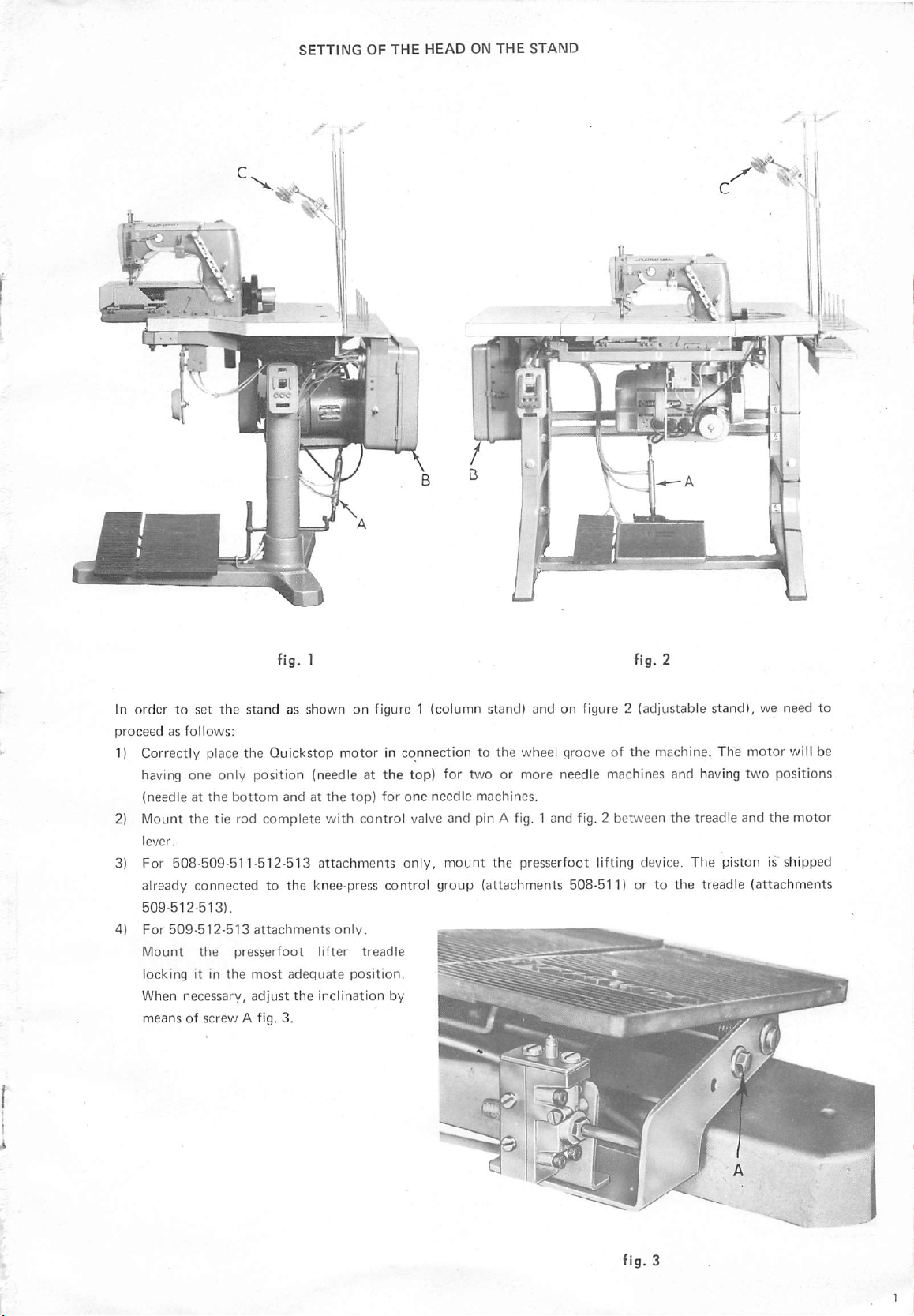
In order to set the stand as shown on figure 1 (column stand) and on figure 2 (adjustable stand), we need to
proceedasfollows;
1) Correctly place
having one only position (needle at
(needleatthe
2) Mount
the
bottom
tie rod
the
Quickstop
complete
motorinconnectiontothe
the
top)
for two or
andatthe
top)
for
one
needle
with control valve and pin A fig. 1 and fig. 2 between
wheel groove of
more
machines.
needle machines and having two positions
the
machine. The
the
motor
treadle and
the
will be
motor
3) For 508-509-511-512-513
already
509-512-513).
connected
to the knee-press control
attachments
only,
mount
group
the presserfoot lifting device.
(attachments
508-511) or to
the
The
piston is'shipped
treadle
(attachments
ifi

5) For 508-511 attachments only For submerged adjustable stand mount the presserfoot lifting knee-press on
the
front
cross
brace
fig. 4.
For normal adjustable stand
mount
the knee-press on
the
table fig. 5
For column stand mount the knee-press on the head support fig. 6
6) For
513-514
attachments
only
Mount the stitch closing-up control knee-press following the procedure as per point 5.
7) Carry
out
the mounting of the presserfoot lifter piston fixing same with the relative screws
To the crossbrace supporting the machine for setting on adjustable stands or similar ones (fig. 7 submerged
edition)
To
the
(fig. 8
bracket
normal
fig. 9
edition).
for
settingoncolumn
stands.
8) Mount the control box B fig. 1 and 2 fixing it to the bobbin holder (column stand) or to the table (adjustable

9)
Fixinthe
figure 10.
10)
Connect
the
air
rear
partofthe
Tighten
air.
Before
passage of air are
to
the
corresponding
the
various pins to
tubes.
For
connection
box
aretobe
well
the
locking
connecting
carefully
tubeisequipped
holeonthe
the
followed.
screwofthe
every
single pin
cleaned
with
the
table
box
taking
of
the
pins,
instructions
pinsinordertoavoid
make
and
that
seal ring, fig. 10.
pin A by
care
sure
every
meansofflange
nottobendorentangle
indicated
useless loss
that
the
orifices
single
connector
on
for
joined
B
the
of
the
Ik
fig.10
11) Place
the
belt
adjusting tension
Connect
12) Connect
13) Mount on
proportioned
entangled,aminor
•
The
adjustmentiscarried
head on
the
the
the
stand taking care
presserfoot
of same and
lifting
checking
pistontothe
pins joined to the control unit with
the
bobbin-holder shaft the
according to the
locking
type
of yarn used. A greater locking is required for yarns with
for
stable
yarns.
outbyactioniny
not
to damage
the
presserfoot
'C
thread lockings, fig. 1 and fig, 2, The thread locking will be
the
alignment.
the
talMe
above clamping element B fig. 16. Mounj
lifting lever by means of
the
fitted
adjustable
socket as per point 10.
tendency
lever A, fig.
11,
the
tie
to get
drive
rod.
ADJUSTPyiEIMTS
TO BE CARRIED OUT BEFORE COIMNECTING ATTACHMENTS 507-508-509-510.511.512-513-514
TO
THE
COMPRESSED
AIR
LINE.
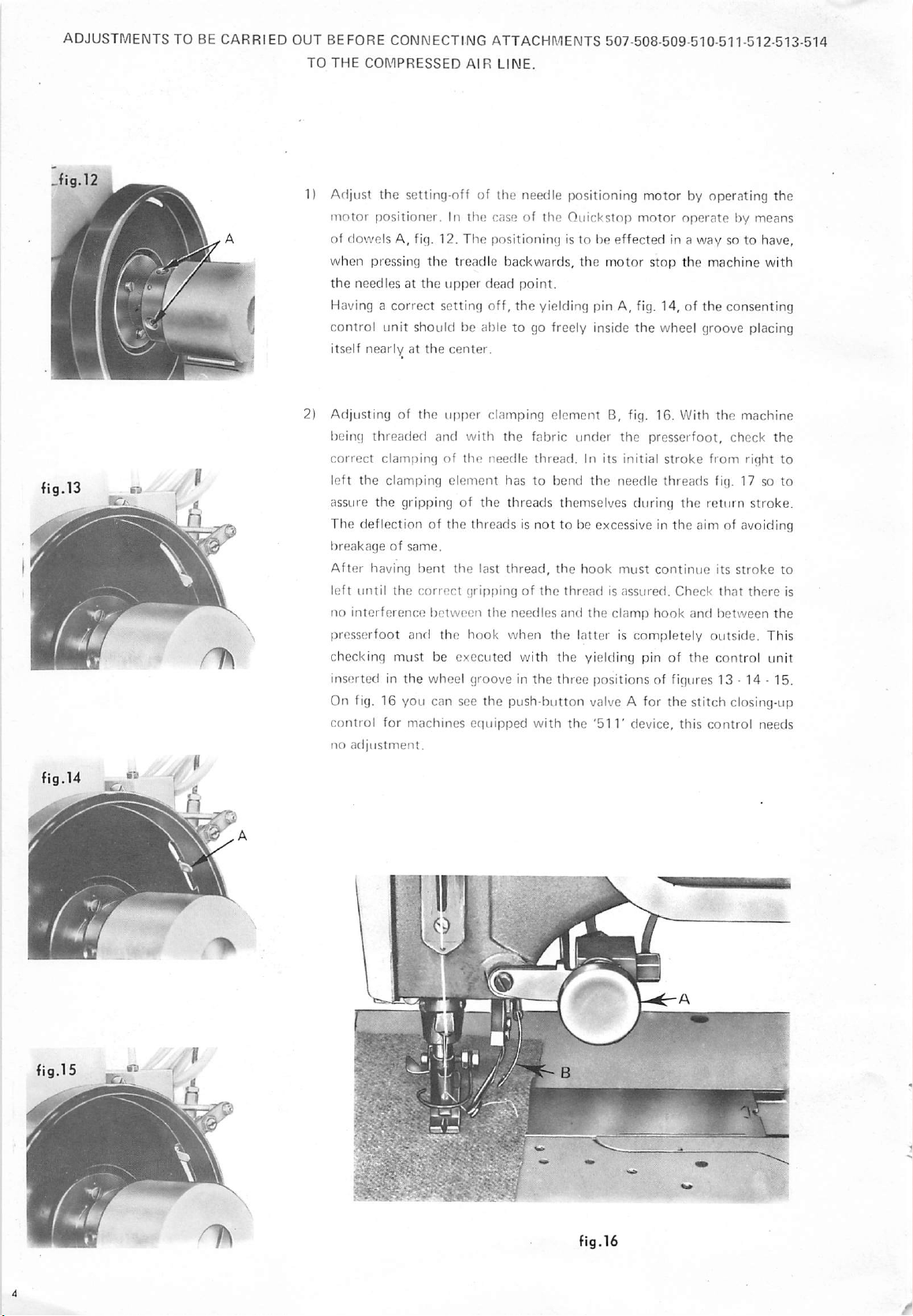
1) Adjust
motor
of
when
the
Having a
control
itself
2) Adjusting of
being
correct
left
assure
The deflection of the threads is
breakageofsame.
After
left
no
presserfoot
checking must be executed with
inserted in
the
setting-nff of the needle positioning
positioner.Inthe
dowels
A, fig. 12.
pressing
needles at
correct
unit
should be able to go freely inside
nearlyatthe
threaded
clamping of
the
clamping
the
gripping of
having
until
the
interference
and
the
case of
The
positioning
the
treadle
the
upper
dead
setting
off,
center.
the
upper
clamping
and
with
the
needle
element
the
bent
the
last
correct
grippingofthe
between
the
hook
the
wheel groove in
the
Quickstop
is to be
backwards,
the
motor
point.
the
yielding pin A, fig. 14, of
element
the
fabric
thread.
hastobend
threads
thread,
needles
when
themselves
not
to be excessive in the aim of avoiding
the
and
the
the
the
three
B, fig. 16. With
under
In its initial
the
hook
thread
is asstired.
the
latteriscompletely
yielding pin of
[jositions of figures 13 • 14 • 15.
motor
motor
effected
the
the
needle
during
must
clamp
by operating the
operatebymeans
in a
way
stop
the
machine
the
wheel groove placing
the
presserfoot,
stroke
from
threads
continue
hook
the
Check
and
fig. 17 so to
return
its
that
between
outside.
the
control unit
On fig. 16 you can see the push-button valve A for the stitch closing-up
control
no
for
adjustment.
machines
cciuipped
with
the
'511'
device, this
control
so to have,
with
consenting
machine
check
the
right
stroke.
stroke
there
the
This
needs
to
to
is
a «
iB-
-y
i X
fig.16
 Loading...